EP3005870B1 - Dual-bearing reel - Google Patents
Dual-bearing reel Download PDFInfo
- Publication number
- EP3005870B1 EP3005870B1 EP15171723.8A EP15171723A EP3005870B1 EP 3005870 B1 EP3005870 B1 EP 3005870B1 EP 15171723 A EP15171723 A EP 15171723A EP 3005870 B1 EP3005870 B1 EP 3005870B1
- Authority
- EP
- European Patent Office
- Prior art keywords
- spool shaft
- disposed
- bearing
- outer race
- way clutch
- Prior art date
- Legal status (The legal status is an assumption and is not a legal conclusion. Google has not performed a legal analysis and makes no representation as to the accuracy of the status listed.)
- Active
Links
- 230000009977 dual effect Effects 0.000 title claims description 29
- 238000005266 casting Methods 0.000 claims description 53
- 238000005096 rolling process Methods 0.000 claims description 32
- 230000002093 peripheral effect Effects 0.000 claims description 23
- 230000007246 mechanism Effects 0.000 description 67
- 238000004804 winding Methods 0.000 description 27
- 238000010276 construction Methods 0.000 description 25
- 230000004048 modification Effects 0.000 description 12
- 238000012986 modification Methods 0.000 description 12
- 230000004308 accommodation Effects 0.000 description 10
- OKTJSMMVPCPJKN-UHFFFAOYSA-N Carbon Chemical compound [C] OKTJSMMVPCPJKN-UHFFFAOYSA-N 0.000 description 7
- 229910052799 carbon Inorganic materials 0.000 description 6
- 239000004744 fabric Substances 0.000 description 6
- 230000005540 biological transmission Effects 0.000 description 4
- 230000008878 coupling Effects 0.000 description 4
- 238000010168 coupling process Methods 0.000 description 4
- 238000005859 coupling reaction Methods 0.000 description 4
- 238000006073 displacement reaction Methods 0.000 description 4
- 230000001105 regulatory effect Effects 0.000 description 4
- 241000276420 Lophius piscatorius Species 0.000 description 1
- 230000004323 axial length Effects 0.000 description 1
- 230000007423 decrease Effects 0.000 description 1
- 229910002804 graphite Inorganic materials 0.000 description 1
- 239000010439 graphite Substances 0.000 description 1
- 239000000463 material Substances 0.000 description 1
- 230000004044 response Effects 0.000 description 1
- 230000000717 retained effect Effects 0.000 description 1
- 210000003813 thumb Anatomy 0.000 description 1
Images


Classifications
-
- A—HUMAN NECESSITIES
- A01—AGRICULTURE; FORESTRY; ANIMAL HUSBANDRY; HUNTING; TRAPPING; FISHING
- A01K—ANIMAL HUSBANDRY; AVICULTURE; APICULTURE; PISCICULTURE; FISHING; REARING OR BREEDING ANIMALS, NOT OTHERWISE PROVIDED FOR; NEW BREEDS OF ANIMALS
- A01K89/00—Reels
- A01K89/02—Brake devices for reels
- A01K89/033—Brake devices for reels with a rotary drum, i.e. for reels with a rotating spool
- A01K89/05—Brakes connected to the spool by one-way clutch
-
- A—HUMAN NECESSITIES
- A01—AGRICULTURE; FORESTRY; ANIMAL HUSBANDRY; HUNTING; TRAPPING; FISHING
- A01K—ANIMAL HUSBANDRY; AVICULTURE; APICULTURE; PISCICULTURE; FISHING; REARING OR BREEDING ANIMALS, NOT OTHERWISE PROVIDED FOR; NEW BREEDS OF ANIMALS
- A01K89/00—Reels
- A01K89/003—Devices for transferring line to a reel
-
- A—HUMAN NECESSITIES
- A01—AGRICULTURE; FORESTRY; ANIMAL HUSBANDRY; HUNTING; TRAPPING; FISHING
- A01K—ANIMAL HUSBANDRY; AVICULTURE; APICULTURE; PISCICULTURE; FISHING; REARING OR BREEDING ANIMALS, NOT OTHERWISE PROVIDED FOR; NEW BREEDS OF ANIMALS
- A01K89/00—Reels
- A01K89/015—Reels with a rotary drum, i.e. with a rotating spool
- A01K89/0155—Antibacklash devices
-
- A—HUMAN NECESSITIES
- A01—AGRICULTURE; FORESTRY; ANIMAL HUSBANDRY; HUNTING; TRAPPING; FISHING
- A01K—ANIMAL HUSBANDRY; AVICULTURE; APICULTURE; PISCICULTURE; FISHING; REARING OR BREEDING ANIMALS, NOT OTHERWISE PROVIDED FOR; NEW BREEDS OF ANIMALS
- A01K89/00—Reels
- A01K89/02—Brake devices for reels
- A01K89/033—Brake devices for reels with a rotary drum, i.e. for reels with a rotating spool
- A01K89/045—Spool bearing brake
-
- A—HUMAN NECESSITIES
- A01—AGRICULTURE; FORESTRY; ANIMAL HUSBANDRY; HUNTING; TRAPPING; FISHING
- A01K—ANIMAL HUSBANDRY; AVICULTURE; APICULTURE; PISCICULTURE; FISHING; REARING OR BREEDING ANIMALS, NOT OTHERWISE PROVIDED FOR; NEW BREEDS OF ANIMALS
- A01K89/00—Reels
- A01K89/02—Brake devices for reels
- A01K89/033—Brake devices for reels with a rotary drum, i.e. for reels with a rotating spool
- A01K89/057—Axially engaged
- A01K89/058—Coaxial with spool
Definitions
- the present invention relates to a dual-bearing reel, particularly to a brake device configured to brake a spool shaft in the dual-bearing reel.
- a dual-bearing reel is equipped with a brake device called a casting control mechanism configured to brake a spool shaft by making contact with the both ends of the spool shaft.
- a well-known brake device for casting control is configured to act even in winding a fishing line. Hence, rotational resistance occurs in winding the fishing line.
- a type of well-known brake device has been produced that prevents occurrence of braking force with use of a one-way clutch in winding the fishing line (see e.g., Japan Laid-open Patent Application Publication No. H10-174540 ).
- the well-known brake device includes a tapered tube, a tapered coil spring and an operating member.
- the tapered tube is mounted in alignment with a gear and is configured to be unitarily rotated with the spool shaft.
- the tapered coil spring is contactable with the outer peripheral part of the tapered tube.
- the operating member is configured to extend and compress the tapered coil spring. One end of the tapered coil spring is hooked to the operating member, whereas the other end of the tapered coil spring makes contact with the gear.
- the coiled diameter of the tapered coil spring decreases and the tapered coil spring is wound onto the tapered tube.
- the spool shaft is braked through the tapered tube.
- the tapered coil spring herein functions as a one-way clutch and a brake member.
- the leading end (one end) of the coil spring is fixed to a braking force regulating knob (the operating member).
- rotational force inevitably acts on the braking force regulating knob in application of braking force. This may cause a situation that a braking force regulating position is displaced and braking force becomes unstable.
- the terminal end (the other end) of the coil spring makes contact with the gear configured to be unitarily rotated with the spool.
- frictional force is necessarily produced between the gear and the one-way clutch. Therefore, the brake device produces rotational resistance against the spool shaft in winding the fishing line.
- JP2000157120A discloses a rotational control mechanism for a dual bearing reel.
- a dual-bearing reel includes a reel unit, a spool for winding a fishing line, a spool and a brake device.
- the spool is rotatable with respect to the reel unit.
- the spool shaft is rotatably supported by the reel unit and is configured to be unitarily rotated with the spool.
- the brake device is configured to brake the spool shaft.
- the brake device herein includes a one-way clutch, an operating member and a pressing member.
- the one-way clutch has a first inner race, a first outer race and a first rolling element. The first inner race is integrated and unitarily rotatable with the spool shaft.
- the first outer race is disposed on an outer peripheral side of the first inner race and is rotatable with respect to the reel unit.
- the first rolling element is disposed between the first inner race and the first outer race.
- the one-way clutch is configured to receive rotation of the spool shaft only in a fishing-line casting direction through the first outer race.
- the operating member is disposed on an outer peripheral side of a first end of the spool shaft, and is engaged with the reel unit so as to be movable in a spool shaft direction when being operated and rotated.
- the pressing member is configured to press the first outer race in conjunction with movement of the operating member.
- the first outer race is restricted from moving oppositely to the pressing member in the spool shaft direction with respect to the reel unit.
- the brake device does not apply rotational resistance to the spool shaft.
- the rotation of the spool shaft is transmitted to the first outer race from the first inner race through the first rolling element.
- the first outer race is braked while being pressed by the pressing member and being restricted from moving oppositely to the pressing member in the spool shaft direction with respect to the reel unit. Accordingly, the spool shaft is braked.
- the one-way clutch herein used is of a roller type, and hence, the brake device does not produce rotational resistance against the spool shaft in winding the fishing line. Furthermore, the first outer race is herein configured to be braked, and thus, the braking force occurs at a large diameter. Accordingly, the brake device can obtain a significant braking forcee. Moreover, the frictional area is enlarged, and this stabilizes braking force and enhances component durability.
- the first inner race is integrated with the spool shaft.
- the one-way clutch can be simply constructed.
- the pressing member may be a friction plate mounted to the operating member.
- the first outer race can be braked on the side that the operating member is disposed.
- the spool shaft may be rotatably supported by a rolling bearing.
- the rolling bearing has a second outer race, a second inner race and a second rolling element.
- the second outer race is located on an opposite side of the operating member through the one-way clutch and is non-rotatably mounted to the reel unit.
- the second inner race is mounted to an outer periphery of the spool shaft so as to be disposed closely to the first end.
- the second rolling element is disposed between the second outer race and the second inner race.
- the second inner race may be restricted from moving oppositely to the pressing member with respect to the spool shaft.
- the first outer race can be braked while being restricted from axially moving by the pressing member and the rolling bearing that is restricted from moving oppositely to the pressing member with respect to the spool shaft.
- the brake device may include an urging member disposed between the one-way clutch and the rolling bearing.
- an urging member disposed between the one-way clutch and the rolling bearing.
- the brake device may include a washer member that is disposed on an opposite side of the operating member through the one-way clutch and is mounted to the reel unit so as to be immovable oppositely to the pressing member.
- the one-way clutch is not required to directly make contact with the reel unit. This enables accurate braking of the first outer race.
- the brake device may include an urging member disposed between the one-way clutch and the washer member.
- the range of braking force to be adjusted by the operating member is widened, and this enables minute adjustment of the braking force.
- the operating member may be configured to press a first end side of the spool shaft.
- the one-way clutch may be mounted to the spool shaft so as to be disposed closely to a second end opposite to the first end.
- the pressing member may be mounted to the spool shaft so as to be capable of pressing the one-way clutch toward the second end.
- the one-way clutch can be disposed on the opposite side of the side that the operating member is disposed (e.g., a handle side) in the dual-bearing reel.
- the brake device may include an urging member disposed between the pressing member and the one-way clutch.
- the range of the braking force to be adjusted by the operating member is widened, and this enables minute adjustment of the braking force.
- the urging member may be a disc spring disposed so as to be compressible.
- the urging member can be disposed in a slight gap produced in the spool shaft direction. Thus, even when the urging member is provided, it is possible to prohibit an increase in the dimension of the brake device in the spool shaft direction.
- the one-way clutch herein used is of a roller type, and thus, the brake device does not produce rotational resistance against the spool shaft in winding the fishing line. Furthermore, the first outer race is herein braked, and hence, braking force occurs at a large diameter and frictional area is enlarged. Accordingly, large braking force is obtainable by the brake device.
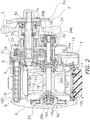
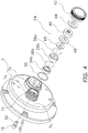
- a dual-bearing reel 100 employing a preferred embodiment of the present invention includes a reel unit 1, a handle 2, a spool 12, a spool shaft 16 and a casting control mechanism 24.
- the reel unit 1 includes a frame 5, first and second side covers 6 and 7 attached to the both lateral sides of the frame 5, and a mechanism mount plate 13.
- the frame 5 is composed of a first side plate 8, a second side plate 9, a front coupling portion 10a and a bottom coupling portion 10b.
- the first and second side plates 8 and 9 are disposed in opposition to each other at a predetermined interval.
- the front and bottom coupling portions 10a and 10b couple the first side plate 8 and the second side plate 9.
- a fishing rod attachment leg 4 for attaching a fishing rod is integrally formed with the bottom coupling portion 10b.
- the first side cover 6 has a roughly circular shape when seen from the outside of the dual-bearing reel 100 in a spool shaft direction.
- the second side cover 7 is composed of two eccentric circular parts with different outer diameters.
- the first side cover 6 is integrally formed with the first side plate 8.
- the first side plate 8 has a bearing accommodation part 8a in the center thereof.
- the bearing accommodation part 8a has a tubular shape and accommodates a bearing 29a.
- the second side cover 7 is fixed to the second side plate 9 by, for instance, three screws.
- the second side cover 7 has a first boss 7a and a second boss 7b.
- the first boss 7a supports the spool shaft 16 to be described, whereas the second boss 7b supports a drive shaft 30 to be described. Furthermore, the first boss 7a is disposed higher than and rearward of the second boss 7b.
- the first boss 7a has a male threaded part 7c and an annular groove 7d formed adjacently to the male threaded part 7c on the outer peripheral surface thereof.
- An operating member 42 to be described is screwed onto the male threaded part 7c.
- a seal member 36 made in the form of O-ring with elasticity, is fitted to the annular groove 7d.
- the mechanism mount plate 13 is provided for supporting the drive shaft 30, a pinion gear 32 and the spool shaft 16, which are to be described.
- the mechanism mount plate 13 is detachably attached to the second side cover 7, and is also detachably attached to the second side plate 9 while being integrated with the second side cover 7.
- the mechanism mount plate 13 has a support part 13a for supporting the pinion gear 32 and the spool shaft 16 in a rotatable state.
- the support part 13a has a tubular shape and protrudes from both surfaces of the mechanism mount plate 13.
- the handle 2 has a handle arm 2a and a handle knob 2b.
- the handle arm 2a is mounted to the drive shaft 30 (see FIG. 2 ) so as to be unitarily rotatable therewith.
- the handle knob 2b is rotatably mounted to the tip end of the handle arm 2a.
- the handle arm 2a is disposed axially outside a star drag 3.
- the frame 5 accommodates the spool 12, a clutch lever 17 and a level wind mechanism 18.
- the clutch lever 17 serves as a thumb pad in thumbing the fishing line.
- the level wind mechanism 18 is configured to evenly wind the fishing line about the spool 12.
- a rotation transmission mechanism 19, a clutch mechanism 21, a clutch control mechanism 22, a drag mechanism 23 and the casting control mechanism 24 are disposed between the frame 5 and the second side cover 7.
- the casting control mechanism 24 is an exemplary brake device of the present invention.
- a centrifugal brake mechanism 25 is disposed between the frame 5 and the first side cover 6 in order to prohibit the occurrence of backlash when casting.
- the rotation transmission mechanism 19 is configured to transmit rotational force from the handle 2 to the spool 12 and the level wind mechanism 18.
- the rotation transmission mechanism 19 includes the drive shaft 30, a drive gear 31 fixed to the drive shaft 30, and the tubular pinion gear 32 meshed with the drive gear 31.
- the handle 2 is coupled to the tip end of the drive shaft 30 so as to be unitarily rotatable therewith.
- the drive gear 31 is coupled to the drive shaft 30 through the drag mechanism 23 so as to be unitarily rotatable therewith.
- the pinion gear 32 is disposed on the outer peripheral side of the spool shaft 16, and functions as the clutch mechanism 21 as well.
- the pinion gear 32 is supported by the reel unit 1 through bearings 34a and 34b so as to be rotatable and axially movable.
- the bearing 34a is mounted to the support part 13a of the mechanism mount plate 13, whereas the bearing 34b is mounted to the first boss 7a so as to be axially aligned with a bearing 29b to be described as shown in FIG. 3 .
- the clutch mechanism 21 is disposed in an intermediate position within the rotation transmission mechanism 19.
- the clutch mechanism 21 is switchable between a clutch-on state and a clutch-off state.
- the drive shaft 30 and the spool 12 are coupled in the clutch-on state and are decoupled in the clutch-off state.
- the clutch control mechanism 22 is configured to control and switch the clutch mechanism 21 between the clutch-on state and the clutch-off state in response to an operation of the clutch lever 17.
- the clutch mechanism 21 is set in the clutch-off state
- the spool 12 is freely rotatable and the fishing line is releasable.
- the fishing line is windable about the spool 12 by rotation of the handle 2.
- the spool 12 is a member for winding the fishing line and is rotatable with respect to the reel unit 1.
- the spool 12 is coupled to the spool shaft 16 so as to be unitarily rotatable therewith.
- the spool 12 has a bobbin trunk 12a and a pair of flanges 12b.
- the bobbin trunk 12a is a part around which the fishing line is wound.
- the flanges 12b are large diameter parts integrally formed with the both axial sides of the bobbin trunk 12a.
- the spool shaft 16 is coupled to the inner peripheral side of the bobbin trunk 12a of the spool 12.
- the spool shaft 16 is rotatably supported by the reel unit 1. Specifically, the spool shaft 16 is rotatably supported by the reel unit 1 through three bearings 29a, 29b and 29c.
- the spool shaft 16 has a first end 16c and a second end 16d.
- the first end 16c is disposed on the handle 2 side, whereas the second end 16d is disposed on the opposite side of the first end 16c.
- Each of the first and second ends 16c and 16d is disposed away from its opposed component through a gap.
- the bearing 29a is accommodated in the bearing accommodation part 8a of the first side plate 8.
- the bearing 29b is accommodated in the first boss 7a of the second side cover 7.
- the bearings 29a and 29b are rolling-element bearings.
- the bearings 29b and 34b disposed in alignment within the first boss 7a, are retained by retainer members 38a and 38b.
- the bearing 29c is mounted to the support part 13a of the mechanism mount plate 13.
- the bearing 29c is a plain bearing.
- gaps are produced between both ends of the spool shaft 16 and their opposed components.
- the spool shaft 16 has a first step 16a (see FIG. 2 ) and a second step 16b (see FIG. 3 ) for restricting axial movement.
- the first step 16a is formed on a part to which the bearing 29a is mounted, whereas the second step 16b is formed on a part to which the bearing 29b is mounted.
- the casting control mechanism 24 is configured to brake the spool shaft 16. As shown in FIGS. 3 and 4 , the casting control mechanism 24 includes a one-way clutch 40 of a roller clutch type, the operating member 42, a pressing member 44, an urging member 46 and a washer member 48.
- the one-way clutch 40 is disposed within the first boss 7a so as to be axially aligned with the bearing 29b.
- the one-way clutch 40 includes a first inner race 50, a first outer race 52 and a first rolling element 54.
- the first inner race 52 is unitarily rotatable with the spool shaft 16.
- the first outer race 52 is disposed on the outer peripheral side of the first inner race 50, and is rotatable with respect to the reel unit 1.
- the first rolling element 54 is disposed between the first inner race 50 and the first outer race 52.
- the first rolling element 54 is a cylindrical roller.
- the one-way clutch 40 is configured to receive rotation of the spool shaft 16 only in the fishing-line releasing direction through the first outer race 52.
- the first inner race 50 is integrated with the spool shaft 16.
- the first outer race 52 is restricted from moving oppositely to the pressing member 44 in the axial direction of the spool shaft 16 with respect to the reel unit 1.
- the first outer race 52 is disposed away from the inner peripheral surface of the first boss 7a through a gap, and is restricted from moving oppositely to the pressing member 44 in the axial direction of the spool shaft 16 by the urging member 46 through the washer member 48.
- the bearing 29b is mounted to a first end 16c side part of the spool shaft 16 (i.e., a right end part in FIG. 2 ; a handle-side end part of the spool shaft 16).
- the bearing 29b includes a second outer race 29d, a second inner race 29e and a second rolling element 29f.
- the second outer race 29d is non-rotatably mounted to the first boss 7a of the reel unit 1 on the opposite side of the operating member 42 through the one-way clutch 40.
- the second inner race 29e is disposed on the outer peripheral part of the spool shaft 16.
- the second rolling element 29f is disposed between the second outer race 29d and the second inner race 29e.
- the second inner race 29e is restricted from moving oppositely to the pressing member 44 with respect to the spool shaft 16 by the second step 16b. Furthermore, the spool shaft 16 is restricted from moving oppositely to the pressing member 44 by the first step 16a.
- the operating member 42 is disposed on the outer peripheral side of the first end 16c of the spool shaft 16, and is engaged with the first boss 7a so as to be movable in the spool shaft direction when operated and rotated.
- the operating member 42 is a closed-end tubular member, and is mounted to the outer peripheral surface of the first boss 7a.
- the operating member 42 has a female threaded part 42a and a seal contact part 42b on the inner peripheral surface thereof.
- the female threaded part 42a is screwed onto the male threaded part 7c.
- the seal contact part 42b is contactable to the seal member 36.
- the operating member 42 has a circular mount recess 42c that the pressing member 44 is mounted to the bottom thereof.
- the seal member 36 prevents intrusion of foreign objects into the interior of the reel unit 1 and applies rotational resistance in order to prevent the operating member 42 from rotating against angler's intention.
- the pressing member 44 is configured to press the first outer race 52 in accordance with rotation of the operating member 42.
- the pressing member 44 is made of, for instance, carbon cloth.
- the pressing member 44 is an annular friction plate of a washer type and is mounted to the mount recess 42c of the operating member 42.
- the urging member 46 is a disc spring, for instance, and is disposed between the one-way clutch 40 and the bearing 29b so as to be extendable and compressible.
- the outer peripheral part of the urging member 46 indirectly makes contact with the first outer race 52 through the washer member 48, whereas the inner peripheral part of the urging member 46 directly makes contact with the second inner race 29e.
- the urging member 46 minutely adjusts the braking force by extending a range of braking force to be adjusted by the operating member 42.
- a distance L1 between the first end 16c of the spool shaft 16 and the mount recess 42c of the operating member 42 is herein set to be greater than a displacement L2 of the urging member 46 between its non-compressed state and its maximally compressed state (L1>L2).
- the washer member 48 is a member made of carbon cloth exerting high sliding performance.
- the fishing line is reeled out from the spool 12 by the weight of a terminal tackle, and the spool shaft 16 is rotated in the fishing-line casting direction.
- the fishing-line casting directional rotation of the spool shaft 16 is transmitted to the first outer race 52 through the first rolling element 54 in the one-way clutch 40, and the first outer race 52 is thereby rotated.
- the first outer race 52 is pressed by the pressing member 44 and is braked with braking force set in accordance with an operating position of the operating member 42. At this time, large braking force is obtainable because the braking force is produced by pressing and holding the first outer race 52 from its both lateral sides.
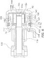
- a spool shaft 116 is supported by a one-way clutch 140 and the bearing 29a. Furthermore, a pinion gear 132 is supported by the bearing 34a.
- a casting control mechanism 124 includes the one-way clutch 140, the operating member 42, a pressing member 144, an urging member 146 and a washer member 148.
- the one-way clutch 140 is a roller clutch of an inner race free-wheeling type, and includes a first inner race 150, a first outer race 152 and a first rolling element 154.
- the first inner race 150 is integrated with the spool shaft 116.
- the first outer race 152 is disposed on the outer peripheral side of the first inner race 150 so as to be away from the inner peripheral surface of the first boss 7a through a gap, and is rotatable with respect to the first boss 7a.
- the first rolling element 154 is disposed between the first inner race 150 and the first outer race 152.
- the operating member 42 has the same construction as that of the first preferred embodiment, and has the circularly dented mount recess 42c.
- the pressing member 144 is composed of a first pressing member 144a and a second pressing member 144b.
- the first pressing member 144a is mounted to the mount recess 42c of the operating member 42.
- the second pressing member 144b is disposed between the first pressing member 144a and the first outer race 152.
- the first pressing member 144a and the second pressing member 144b are disc-shaped members made of, for instance, carbon cloth.
- the urging member 146 is a disc spring, for instance, and is disposed between the first outer race 152 and the washer member 148 so as to be extendable and compressible.
- the outer peripheral part of the urging member 146 indirectly makes contact with a wall surface 7e of the first boss 7a through the washer member 148, whereas the inner peripheral part of the urging member 146 directly makes contact with a lateral surface of the first outer race 152.
- the distance L1 between the second pressing member 144b and a first end 116c of the spool shaft 116 is herein set to be greater than the displacement L2 of the urging member 146 between its non-compressed state and its maximally compressed state (L1>L2). With the setting, even when the urging member 146 is completely compressed, the first end 116c of the spool shaft 116 does not make contact with the second pressing member 144b.
- the washer member 148 is a member made of, for instance, carbon graphite cloth.
- the washer member 148 makes contact with the wall surface 7e of the first boss 7a, and is restricted from moving oppositely to the pressing member 144.
- the fishing-line casting directional rotation is transmitted to the first outer race 152 through the first rolling element 154 in the one-way clutch 140, and the first outer race 152 is thereby rotated.
- the first outer race 152 is pressed by the pressing member 144 and is braked with braking force set in accordance with an operating position of the operating member 42. At this time, large braking force is obtainable because the braking force is produced by pressing and holding the first outer race 152 from its both lateral sides.
- a casting control mechanism of the second modification has a construction roughly the same as that of the first modification, but includes two washer members 148 instead of the urging member 146. Except for the above, the construction of the casting control mechanism of the second modification is the same as that of the casting control mechanism of the first modification, and therefore, explanation thereof will not be hereinafter provided. It should be noted that the casting control mechanism of the second modification does not include the urging member 46, and hence, the adjustable range of braking force is narrowed, making it difficult to minutely adjust the braking force.
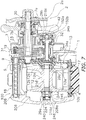
- a casting control mechanism 224 includes a one-way clutch 240, the operating member 42, a pressing member 244, an urging member 246 and a washer member 248.
- the operating member 42 has the same construction as that of the first preferred embodiment, and is mounted to the handle 2 side.
- the casting control mechanism 224 includes two disc-shaped fiction plates 152a and 152b mounted to the operating member 42.
- the other components of the casting control mechanism 224 are mounted to a bearing accommodation part 208a of a first side plate 208 on a first side cover 206 side that is opposite to the handle 2 side.
- the bearing accommodation part 208a has an axial length longer than that of the bearing accommodation part 8a of the first preferred embodiment.
- a first end 216c of a spool shaft 216 is configured to be pressed by the friction plates 152a and 152b mounted to the operating member 42.
- the spool shaft 216 is axially movable in accordance with the displacement of the operating member 42.
- a second end 216d of the spool shaft 216 is disposed away from the bearing accommodation part 208a through a gap.
- the one-way clutch 240 is disposed more closely to the first side cover 206 side than the bearing 29a on the second end 216d side of the spool shaft 216.
- the one-way clutch 240 is a roller clutch of an inner race free-wheeling type, and includes a first inner race 250, a first outer race 252 and a first rolling element 254.
- the first inner race 250 is integrated with the spool shaft 216.
- the first outer race 252 is disposed away from the inner peripheral surface of the bearing accommodation part 208a through a gap, and is rotatable with respect to the bearing accommodation part 208a.
- the first outer race 252 is restricted from moving oppositely to the pressing member 244 by the washer member 248.
- the pressing member 244 is composed of a retaining ring 244a and a body member 244b.
- the retaining ring 244a is made of spring material, and is fitted to a mount groove 216e so as to be axially immovable.
- the mount groove 216e is herein annularly formed on the spool shaft 216, and is located on the second end 216d side of the bearing 29a.
- the body member 244b is disposed in contact with the retaining ring 244a.
- the body member 244b is a washer-shaped member made of, for instance, carbon cloth.
- the urging member 246 is a disc spring disposed between the pressing member 244 and the first outer race 252 so as to be extendable and compressible.
- the washer member 248 is a washer-shaped member made of, for instance, carbon cloth. The washer member 248 is disposed so as to interpose the first outer race 252 between itself and the urging member 246, and makes contact with the bottom of the bearing accommodation part 208a.
- the distance L1 between the washer member 248 and the second end 216d of the spool shaft 216 is herein set to be greater than the displacement L2 of the urging member 246 between its non-compressed state and its maximally compressed state (L1>L2). With the setting, even when the urging member 246 is completely compressed, the second end 216d of the spool shaft 216 does not make contact with the washer member 248.
- the fishing-line casting directional rotation is transmitted to the first outer race 252 through the first rolling element 254 in the one-way clutch 240, and the first outer race 252 is thereby rotated.
- the first outer race 252 is pressed by the pressing member 244, and is braked with braking force set in accordance with an opening position of the operating member 42. At this time, large braking force is obtainable because the braking force is produced by pressing and holding the first outer race 252 from both lateral sides.
Landscapes
- Life Sciences & Earth Sciences (AREA)
- Environmental Sciences (AREA)
- Animal Husbandry (AREA)
- Biodiversity & Conservation Biology (AREA)
- Braking Arrangements (AREA)
Applications Claiming Priority (1)
| Application Number | Priority Date | Filing Date | Title |
|---|---|---|---|
| JP2014209304A JP6488098B2 (ja) | 2014-10-10 | 2014-10-10 | 両軸受リール |
Publications (2)
| Publication Number | Publication Date |
|---|---|
| EP3005870A1 EP3005870A1 (en) | 2016-04-13 |
| EP3005870B1 true EP3005870B1 (en) | 2018-05-02 |
Family
ID=53539469
Family Applications (1)
| Application Number | Title | Priority Date | Filing Date |
|---|---|---|---|
| EP15171723.8A Active EP3005870B1 (en) | 2014-10-10 | 2015-06-11 | Dual-bearing reel |
Country Status (7)
| Country | Link |
|---|---|
| US (1) | US9861085B2 (enExample) |
| EP (1) | EP3005870B1 (enExample) |
| JP (1) | JP6488098B2 (enExample) |
| KR (1) | KR102186887B1 (enExample) |
| CN (1) | CN105494278B (enExample) |
| MY (1) | MY174257A (enExample) |
| TW (1) | TWI657738B (enExample) |
Families Citing this family (12)
| Publication number | Priority date | Publication date | Assignee | Title |
|---|---|---|---|---|
| JP6560904B2 (ja) * | 2015-05-27 | 2019-08-14 | 株式会社シマノ | 両軸受リール |
| JP6560903B2 (ja) * | 2015-05-27 | 2019-08-14 | 株式会社シマノ | 両軸受リール |
| JP6649801B2 (ja) * | 2016-02-26 | 2020-02-19 | 株式会社シマノ | 両軸受リール |
| KR101884236B1 (ko) * | 2017-02-03 | 2018-08-01 | 유한책임회사 도요엔지니어링 | 텐션 너트 이탈 방지수단을 구비한 낚시 릴 |
| JP6829654B2 (ja) * | 2017-06-05 | 2021-02-10 | 株式会社シマノ | 釣用リール |
| KR102083429B1 (ko) * | 2017-10-26 | 2020-03-02 | 유한책임회사 도요엔지니어링 | 프론트커버의 탈착이 편리한 낚시 릴 |
| JP7262167B2 (ja) * | 2017-11-22 | 2023-04-21 | 株式会社シマノ | 両軸受リール |
| JP7100990B2 (ja) * | 2018-02-26 | 2022-07-14 | 株式会社シマノ | 電動リール |
| JP7122897B2 (ja) * | 2018-07-19 | 2022-08-22 | 株式会社シマノ | 釣り用リール |
| CN112192778A (zh) * | 2020-09-17 | 2021-01-08 | 丘群香 | 一种拖鞋制造用混合下料装置 |
| JP7666976B2 (ja) * | 2021-04-22 | 2025-04-22 | 株式会社シマノ | 釣用リール |
| JP7689450B2 (ja) * | 2021-06-22 | 2025-06-06 | 株式会社シマノ | 釣用リールのワンウェイクラッチユニット、及び釣用リール |
Family Cites Families (35)
| Publication number | Priority date | Publication date | Assignee | Title |
|---|---|---|---|---|
| DE874224C (de) * | 1945-12-19 | 1953-04-20 | Urfabriken Ab | Vorrichtung an Angelwinden |
| JPS59139072U (ja) * | 1983-03-08 | 1984-09-17 | 株式会社シマノ | 両軸受リ−ル |
| JPH0418377Y2 (enExample) * | 1986-09-22 | 1992-04-23 | ||
| JP2562712Y2 (ja) * | 1989-12-05 | 1998-02-16 | 株式会社シマノ | 釣り用リール |
| US5161750A (en) | 1989-12-05 | 1992-11-10 | Shimano Industrial Co., Ltd. | Fishing reel with transmission switching mechanism |
| JP2502204Y2 (ja) * | 1990-11-13 | 1996-06-19 | リョービ株式会社 | 両軸受リ―ルのブレ―キ機構 |
| JPH10174540A (ja) * | 1996-12-18 | 1998-06-30 | Mamiya Op Co Ltd | 両軸受リール |
| US6053444A (en) * | 1997-03-18 | 2000-04-25 | Diawa Seiko, Inc. | Fishline guide device for double bearing type reel |
| JPH10327722A (ja) * | 1997-05-30 | 1998-12-15 | Shimano Inc | 両軸受リールの制動装置 |
| JPH11215940A (ja) | 1997-11-28 | 1999-08-10 | Mamiya Op Co Ltd | 両軸受リール |
| JPH11276034A (ja) * | 1998-03-27 | 1999-10-12 | Daiwa Seiko Inc | 魚釣用リール |
| JP3562976B2 (ja) * | 1998-10-07 | 2004-09-08 | ダイワ精工株式会社 | 魚釣用リール |
| JP2000157120A (ja) * | 1998-11-27 | 2000-06-13 | Shimano Inc | 両軸受リールの制動機構 |
| JP2001025341A (ja) * | 1999-07-14 | 2001-01-30 | Mamiya Op Co Ltd | 釣用リール |
| US6354525B1 (en) * | 1999-11-05 | 2002-03-12 | Shin A Sports Co., Ltd. | Spinning reel with drag brake mechanism and clutch |
| US6530535B2 (en) * | 2000-03-16 | 2003-03-11 | Daiwa Seiko, Inc. | Fishing reel |
| US6896216B2 (en) * | 2001-08-27 | 2005-05-24 | Daiwa Seiko, Inc. | Fishing reel |
| JP2003079294A (ja) * | 2001-09-10 | 2003-03-18 | Shimano Inc | スピニングリール |
| JP2003339283A (ja) * | 2002-05-30 | 2003-12-02 | Daiwa Seiko Inc | 魚釣用両軸受型リ−ル |
| JP2007029015A (ja) * | 2005-07-28 | 2007-02-08 | Daiwa Seiko Inc | 魚釣用両軸受型リ−ル |
| JP4916696B2 (ja) * | 2005-10-13 | 2012-04-18 | シマノコンポネンツ マレーシア エスディーエヌ.ビーエッチディー. | 両軸受リール |
| JP2009124942A (ja) * | 2007-11-19 | 2009-06-11 | Daiwa Seiko Inc | 魚釣用リール |
| TW200930289A (en) | 2008-01-08 | 2009-07-16 | wen-xiang Li | Fishing reel with second brake device |
| JP5159479B2 (ja) * | 2008-07-08 | 2013-03-06 | 株式会社シマノ | 両軸受リールのドラグ機構 |
| EP2143329B1 (en) * | 2008-07-08 | 2011-12-28 | Shimano, Inc. | Drag mechanism for dual-bearing reel |
| JP5143648B2 (ja) * | 2008-07-08 | 2013-02-13 | 株式会社シマノ | レバードラグ型の両軸受リール |
| JP5097630B2 (ja) * | 2008-07-08 | 2012-12-12 | 株式会社シマノ | 両軸受リールの発音装置 |
| JP5590986B2 (ja) * | 2010-06-23 | 2014-09-17 | 株式会社シマノ | 釣り用リールのワンウェイクラッチ |
| JP5536594B2 (ja) | 2010-09-02 | 2014-07-02 | 株式会社シマノ | 両軸受リール |
| MY164166A (en) * | 2010-09-02 | 2017-11-30 | Shimano Kk | Dual-bearing reel |
| JP5718119B2 (ja) * | 2011-03-29 | 2015-05-13 | 株式会社シマノ | 両軸受リールの遠心制動装置 |
| JP5755044B2 (ja) | 2011-06-20 | 2015-07-29 | 株式会社シマノ | 両軸受リールのドラグ機構 |
| JP5926564B2 (ja) * | 2012-01-18 | 2016-05-25 | 株式会社シマノ | 両軸受リールのスプール制動装置及び両軸受リール |
| JP6200287B2 (ja) * | 2013-11-14 | 2017-09-20 | シマノコンポネンツ マレーシア エスディーエヌ.ビーエッチディー. | 両軸受リール |
| JP6352756B2 (ja) * | 2014-09-30 | 2018-07-04 | 株式会社シマノ | 釣用リールのトルク制限装置 |
-
2014
- 2014-10-10 JP JP2014209304A patent/JP6488098B2/ja active Active
-
2015
- 2015-06-08 US US14/733,045 patent/US9861085B2/en active Active
- 2015-06-11 EP EP15171723.8A patent/EP3005870B1/en active Active
- 2015-06-19 MY MYPI2015702088A patent/MY174257A/en unknown
- 2015-06-24 TW TW104120342A patent/TWI657738B/zh active
- 2015-07-03 KR KR1020150095136A patent/KR102186887B1/ko active Active
- 2015-10-09 CN CN201510647408.2A patent/CN105494278B/zh active Active
Non-Patent Citations (1)
| Title |
|---|
| None * |
Also Published As
| Publication number | Publication date |
|---|---|
| TWI657738B (zh) | 2019-05-01 |
| CN105494278B (zh) | 2020-05-05 |
| CN105494278A (zh) | 2016-04-20 |
| EP3005870A1 (en) | 2016-04-13 |
| JP2016077174A (ja) | 2016-05-16 |
| JP6488098B2 (ja) | 2019-03-20 |
| US20160100563A1 (en) | 2016-04-14 |
| KR20160042754A (ko) | 2016-04-20 |
| KR102186887B1 (ko) | 2020-12-07 |
| US9861085B2 (en) | 2018-01-09 |
| TW201616963A (zh) | 2016-05-16 |
| MY174257A (en) | 2020-04-01 |
Similar Documents
| Publication | Publication Date | Title |
|---|---|---|
| EP3005870B1 (en) | Dual-bearing reel | |
| JP2016077174A5 (enExample) | ||
| US6286772B1 (en) | Fly fishing reel with adjustable drag system, removable spool and selectable anti-reverse | |
| JP7142133B2 (ja) | 両軸受リールの操作レバー | |
| JP6560903B2 (ja) | 両軸受リール | |
| US9901084B2 (en) | Dual-bearing reel | |
| EP2749165B1 (en) | Dual-bearing reel | |
| US9737061B2 (en) | Dual-bearing reel and clutch mechanism thereof | |
| US8820669B2 (en) | Dual-bearing reel | |
| US10253826B2 (en) | Clutch control mechanism for dual-bearing reel | |
| US20150090822A1 (en) | Dual-bearing reel | |
| US20130075218A1 (en) | Torque limiting device for fishing reel | |
| JP6949661B2 (ja) | スピニングリール用のハンドル組立体、及び、スピニングリール | |
| US10070636B2 (en) | Spool brake device for dual-bearing reel | |
| CN109105345B (zh) | 双轴承绕线轮 | |
| CN108967378B (zh) | 钓用绕线轮 | |
| JP4395409B2 (ja) | 両軸受リールのドラグ機構 | |
| CN108935358B (zh) | 双轴承绕线轮 | |
| JP2009005637A (ja) | 魚釣用リール | |
| JP2020054397A (ja) | 両軸受リール及び制動力調整用の操作レバー | |
| JP2004024119A (ja) | 両軸受リールのスプール軸支持構造 |
Legal Events
| Date | Code | Title | Description |
|---|---|---|---|
| PUAI | Public reference made under article 153(3) epc to a published international application that has entered the european phase |
Free format text: ORIGINAL CODE: 0009012 |
|
| AK | Designated contracting states |
Kind code of ref document: A1 Designated state(s): AL AT BE BG CH CY CZ DE DK EE ES FI FR GB GR HR HU IE IS IT LI LT LU LV MC MK MT NL NO PL PT RO RS SE SI SK SM TR |
|
| AX | Request for extension of the european patent |
Extension state: BA ME |
|
| 17P | Request for examination filed |
Effective date: 20160919 |
|
| RBV | Designated contracting states (corrected) |
Designated state(s): AL AT BE BG CH CY CZ DE DK EE ES FI FR GB GR HR HU IE IS IT LI LT LU LV MC MK MT NL NO PL PT RO RS SE SI SK SM TR |
|
| STAA | Information on the status of an ep patent application or granted ep patent |
Free format text: STATUS: EXAMINATION IS IN PROGRESS |
|
| 17Q | First examination report despatched |
Effective date: 20170629 |
|
| GRAP | Despatch of communication of intention to grant a patent |
Free format text: ORIGINAL CODE: EPIDOSNIGR1 |
|
| STAA | Information on the status of an ep patent application or granted ep patent |
Free format text: STATUS: GRANT OF PATENT IS INTENDED |
|
| INTG | Intention to grant announced |
Effective date: 20171222 |
|
| GRAS | Grant fee paid |
Free format text: ORIGINAL CODE: EPIDOSNIGR3 |
|
| GRAA | (expected) grant |
Free format text: ORIGINAL CODE: 0009210 |
|
| STAA | Information on the status of an ep patent application or granted ep patent |
Free format text: STATUS: THE PATENT HAS BEEN GRANTED |
|
| AK | Designated contracting states |
Kind code of ref document: B1 Designated state(s): AL AT BE BG CH CY CZ DE DK EE ES FI FR GB GR HR HU IE IS IT LI LT LU LV MC MK MT NL NO PL PT RO RS SE SI SK SM TR |
|
| REG | Reference to a national code |
Ref country code: GB Ref legal event code: FG4D |
|
| REG | Reference to a national code |
Ref country code: CH Ref legal event code: EP Ref country code: AT Ref legal event code: REF Ref document number: 994243 Country of ref document: AT Kind code of ref document: T Effective date: 20180515 |
|
| REG | Reference to a national code |
Ref country code: DE Ref legal event code: R096 Ref document number: 602015010596 Country of ref document: DE Ref country code: IE Ref legal event code: FG4D |
|
| REG | Reference to a national code |
Ref country code: FR Ref legal event code: PLFP Year of fee payment: 4 |
|
| REG | Reference to a national code |
Ref country code: NL Ref legal event code: MP Effective date: 20180502 |
|
| REG | Reference to a national code |
Ref country code: LT Ref legal event code: MG4D |
|
| PG25 | Lapsed in a contracting state [announced via postgrant information from national office to epo] |
Ref country code: BG Free format text: LAPSE BECAUSE OF FAILURE TO SUBMIT A TRANSLATION OF THE DESCRIPTION OR TO PAY THE FEE WITHIN THE PRESCRIBED TIME-LIMIT Effective date: 20180802 Ref country code: NO Free format text: LAPSE BECAUSE OF FAILURE TO SUBMIT A TRANSLATION OF THE DESCRIPTION OR TO PAY THE FEE WITHIN THE PRESCRIBED TIME-LIMIT Effective date: 20180802 Ref country code: FI Free format text: LAPSE BECAUSE OF FAILURE TO SUBMIT A TRANSLATION OF THE DESCRIPTION OR TO PAY THE FEE WITHIN THE PRESCRIBED TIME-LIMIT Effective date: 20180502 Ref country code: SE Free format text: LAPSE BECAUSE OF FAILURE TO SUBMIT A TRANSLATION OF THE DESCRIPTION OR TO PAY THE FEE WITHIN THE PRESCRIBED TIME-LIMIT Effective date: 20180502 Ref country code: LT Free format text: LAPSE BECAUSE OF FAILURE TO SUBMIT A TRANSLATION OF THE DESCRIPTION OR TO PAY THE FEE WITHIN THE PRESCRIBED TIME-LIMIT Effective date: 20180502 Ref country code: ES Free format text: LAPSE BECAUSE OF FAILURE TO SUBMIT A TRANSLATION OF THE DESCRIPTION OR TO PAY THE FEE WITHIN THE PRESCRIBED TIME-LIMIT Effective date: 20180502 |
|
| PG25 | Lapsed in a contracting state [announced via postgrant information from national office to epo] |
Ref country code: NL Free format text: LAPSE BECAUSE OF FAILURE TO SUBMIT A TRANSLATION OF THE DESCRIPTION OR TO PAY THE FEE WITHIN THE PRESCRIBED TIME-LIMIT Effective date: 20180502 Ref country code: HR Free format text: LAPSE BECAUSE OF FAILURE TO SUBMIT A TRANSLATION OF THE DESCRIPTION OR TO PAY THE FEE WITHIN THE PRESCRIBED TIME-LIMIT Effective date: 20180502 Ref country code: LV Free format text: LAPSE BECAUSE OF FAILURE TO SUBMIT A TRANSLATION OF THE DESCRIPTION OR TO PAY THE FEE WITHIN THE PRESCRIBED TIME-LIMIT Effective date: 20180502 Ref country code: GR Free format text: LAPSE BECAUSE OF FAILURE TO SUBMIT A TRANSLATION OF THE DESCRIPTION OR TO PAY THE FEE WITHIN THE PRESCRIBED TIME-LIMIT Effective date: 20180803 Ref country code: RS Free format text: LAPSE BECAUSE OF FAILURE TO SUBMIT A TRANSLATION OF THE DESCRIPTION OR TO PAY THE FEE WITHIN THE PRESCRIBED TIME-LIMIT Effective date: 20180502 |
|
| REG | Reference to a national code |
Ref country code: AT Ref legal event code: MK05 Ref document number: 994243 Country of ref document: AT Kind code of ref document: T Effective date: 20180502 |
|
| PG25 | Lapsed in a contracting state [announced via postgrant information from national office to epo] |
Ref country code: EE Free format text: LAPSE BECAUSE OF FAILURE TO SUBMIT A TRANSLATION OF THE DESCRIPTION OR TO PAY THE FEE WITHIN THE PRESCRIBED TIME-LIMIT Effective date: 20180502 Ref country code: PL Free format text: LAPSE BECAUSE OF FAILURE TO SUBMIT A TRANSLATION OF THE DESCRIPTION OR TO PAY THE FEE WITHIN THE PRESCRIBED TIME-LIMIT Effective date: 20180502 Ref country code: DK Free format text: LAPSE BECAUSE OF FAILURE TO SUBMIT A TRANSLATION OF THE DESCRIPTION OR TO PAY THE FEE WITHIN THE PRESCRIBED TIME-LIMIT Effective date: 20180502 Ref country code: RO Free format text: LAPSE BECAUSE OF FAILURE TO SUBMIT A TRANSLATION OF THE DESCRIPTION OR TO PAY THE FEE WITHIN THE PRESCRIBED TIME-LIMIT Effective date: 20180502 Ref country code: AT Free format text: LAPSE BECAUSE OF FAILURE TO SUBMIT A TRANSLATION OF THE DESCRIPTION OR TO PAY THE FEE WITHIN THE PRESCRIBED TIME-LIMIT Effective date: 20180502 Ref country code: CZ Free format text: LAPSE BECAUSE OF FAILURE TO SUBMIT A TRANSLATION OF THE DESCRIPTION OR TO PAY THE FEE WITHIN THE PRESCRIBED TIME-LIMIT Effective date: 20180502 Ref country code: SK Free format text: LAPSE BECAUSE OF FAILURE TO SUBMIT A TRANSLATION OF THE DESCRIPTION OR TO PAY THE FEE WITHIN THE PRESCRIBED TIME-LIMIT Effective date: 20180502 |
|
| REG | Reference to a national code |
Ref country code: CH Ref legal event code: PL |
|
| REG | Reference to a national code |
Ref country code: DE Ref legal event code: R097 Ref document number: 602015010596 Country of ref document: DE |
|
| PG25 | Lapsed in a contracting state [announced via postgrant information from national office to epo] |
Ref country code: IT Free format text: LAPSE BECAUSE OF FAILURE TO SUBMIT A TRANSLATION OF THE DESCRIPTION OR TO PAY THE FEE WITHIN THE PRESCRIBED TIME-LIMIT Effective date: 20180502 Ref country code: SM Free format text: LAPSE BECAUSE OF FAILURE TO SUBMIT A TRANSLATION OF THE DESCRIPTION OR TO PAY THE FEE WITHIN THE PRESCRIBED TIME-LIMIT Effective date: 20180502 |
|
| REG | Reference to a national code |
Ref country code: BE Ref legal event code: MM Effective date: 20180630 |
|
| PLBE | No opposition filed within time limit |
Free format text: ORIGINAL CODE: 0009261 |
|
| STAA | Information on the status of an ep patent application or granted ep patent |
Free format text: STATUS: NO OPPOSITION FILED WITHIN TIME LIMIT |
|
| REG | Reference to a national code |
Ref country code: IE Ref legal event code: MM4A |
|
| PG25 | Lapsed in a contracting state [announced via postgrant information from national office to epo] |
Ref country code: MC Free format text: LAPSE BECAUSE OF FAILURE TO SUBMIT A TRANSLATION OF THE DESCRIPTION OR TO PAY THE FEE WITHIN THE PRESCRIBED TIME-LIMIT Effective date: 20180502 Ref country code: LU Free format text: LAPSE BECAUSE OF NON-PAYMENT OF DUE FEES Effective date: 20180611 |
|
| 26N | No opposition filed |
Effective date: 20190205 |
|
| PG25 | Lapsed in a contracting state [announced via postgrant information from national office to epo] |
Ref country code: IE Free format text: LAPSE BECAUSE OF NON-PAYMENT OF DUE FEES Effective date: 20180611 Ref country code: CH Free format text: LAPSE BECAUSE OF NON-PAYMENT OF DUE FEES Effective date: 20180630 Ref country code: LI Free format text: LAPSE BECAUSE OF NON-PAYMENT OF DUE FEES Effective date: 20180630 |
|
| PG25 | Lapsed in a contracting state [announced via postgrant information from national office to epo] |
Ref country code: SI Free format text: LAPSE BECAUSE OF FAILURE TO SUBMIT A TRANSLATION OF THE DESCRIPTION OR TO PAY THE FEE WITHIN THE PRESCRIBED TIME-LIMIT Effective date: 20180502 Ref country code: BE Free format text: LAPSE BECAUSE OF NON-PAYMENT OF DUE FEES Effective date: 20180630 |
|
| PG25 | Lapsed in a contracting state [announced via postgrant information from national office to epo] |
Ref country code: AL Free format text: LAPSE BECAUSE OF FAILURE TO SUBMIT A TRANSLATION OF THE DESCRIPTION OR TO PAY THE FEE WITHIN THE PRESCRIBED TIME-LIMIT Effective date: 20180502 |
|
| PG25 | Lapsed in a contracting state [announced via postgrant information from national office to epo] |
Ref country code: MT Free format text: LAPSE BECAUSE OF NON-PAYMENT OF DUE FEES Effective date: 20180611 |
|
| PG25 | Lapsed in a contracting state [announced via postgrant information from national office to epo] |
Ref country code: TR Free format text: LAPSE BECAUSE OF FAILURE TO SUBMIT A TRANSLATION OF THE DESCRIPTION OR TO PAY THE FEE WITHIN THE PRESCRIBED TIME-LIMIT Effective date: 20180502 |
|
| PG25 | Lapsed in a contracting state [announced via postgrant information from national office to epo] |
Ref country code: PT Free format text: LAPSE BECAUSE OF FAILURE TO SUBMIT A TRANSLATION OF THE DESCRIPTION OR TO PAY THE FEE WITHIN THE PRESCRIBED TIME-LIMIT Effective date: 20180502 |
|
| PG25 | Lapsed in a contracting state [announced via postgrant information from national office to epo] |
Ref country code: MK Free format text: LAPSE BECAUSE OF NON-PAYMENT OF DUE FEES Effective date: 20180502 Ref country code: HU Free format text: LAPSE BECAUSE OF FAILURE TO SUBMIT A TRANSLATION OF THE DESCRIPTION OR TO PAY THE FEE WITHIN THE PRESCRIBED TIME-LIMIT; INVALID AB INITIO Effective date: 20150611 Ref country code: CY Free format text: LAPSE BECAUSE OF FAILURE TO SUBMIT A TRANSLATION OF THE DESCRIPTION OR TO PAY THE FEE WITHIN THE PRESCRIBED TIME-LIMIT Effective date: 20180502 |
|
| PG25 | Lapsed in a contracting state [announced via postgrant information from national office to epo] |
Ref country code: IS Free format text: LAPSE BECAUSE OF FAILURE TO SUBMIT A TRANSLATION OF THE DESCRIPTION OR TO PAY THE FEE WITHIN THE PRESCRIBED TIME-LIMIT Effective date: 20180902 |
|
| PGFP | Annual fee paid to national office [announced via postgrant information from national office to epo] |
Ref country code: FR Payment date: 20200512 Year of fee payment: 6 |
|
| PGFP | Annual fee paid to national office [announced via postgrant information from national office to epo] |
Ref country code: GB Payment date: 20210519 Year of fee payment: 7 |
|
| PG25 | Lapsed in a contracting state [announced via postgrant information from national office to epo] |
Ref country code: FR Free format text: LAPSE BECAUSE OF NON-PAYMENT OF DUE FEES Effective date: 20210630 |
|
| GBPC | Gb: european patent ceased through non-payment of renewal fee |
Effective date: 20220611 |
|
| REG | Reference to a national code |
Ref country code: DE Ref legal event code: R081 Ref document number: 602015010596 Country of ref document: DE Owner name: SHIMANO INC., SAKAI-SHI, JP Free format text: FORMER OWNERS: SHIMANO INC., SAKAI, OSAKA, JP; SHIMANO COMPONENTS (MALAYSIA) SDN. BHD., PONTIAN, JOHOR, MY |
|
| PG25 | Lapsed in a contracting state [announced via postgrant information from national office to epo] |
Ref country code: GB Free format text: LAPSE BECAUSE OF NON-PAYMENT OF DUE FEES Effective date: 20220611 |
|
| P01 | Opt-out of the competence of the unified patent court (upc) registered |
Effective date: 20230508 |
|
| PGFP | Annual fee paid to national office [announced via postgrant information from national office to epo] |
Ref country code: DE Payment date: 20230502 Year of fee payment: 9 |