EP3003534B1 - Dispositif et procédé de traitement d'eau a l'aide d'ozone - Google Patents
Dispositif et procédé de traitement d'eau a l'aide d'ozone Download PDFInfo
- Publication number
- EP3003534B1 EP3003534B1 EP14806926.3A EP14806926A EP3003534B1 EP 3003534 B1 EP3003534 B1 EP 3003534B1 EP 14806926 A EP14806926 A EP 14806926A EP 3003534 B1 EP3003534 B1 EP 3003534B1
- Authority
- EP
- European Patent Office
- Prior art keywords
- water
- ozone
- ozonation
- reservoir
- cycle
- Prior art date
- Legal status (The legal status is an assumption and is not a legal conclusion. Google has not performed a legal analysis and makes no representation as to the accuracy of the status listed.)
- Active
Links
Images


Classifications
-
- C—CHEMISTRY; METALLURGY
- C02—TREATMENT OF WATER, WASTE WATER, SEWAGE, OR SLUDGE
- C02F—TREATMENT OF WATER, WASTE WATER, SEWAGE, OR SLUDGE
- C02F1/00—Treatment of water, waste water, or sewage
- C02F1/72—Treatment of water, waste water, or sewage by oxidation
- C02F1/78—Treatment of water, waste water, or sewage by oxidation with ozone
-
- C—CHEMISTRY; METALLURGY
- C02—TREATMENT OF WATER, WASTE WATER, SEWAGE, OR SLUDGE
- C02F—TREATMENT OF WATER, WASTE WATER, SEWAGE, OR SLUDGE
- C02F2201/00—Apparatus for treatment of water, waste water or sewage
- C02F2201/002—Construction details of the apparatus
- C02F2201/005—Valves
-
- C—CHEMISTRY; METALLURGY
- C02—TREATMENT OF WATER, WASTE WATER, SEWAGE, OR SLUDGE
- C02F—TREATMENT OF WATER, WASTE WATER, SEWAGE, OR SLUDGE
- C02F2201/00—Apparatus for treatment of water, waste water or sewage
- C02F2201/78—Details relating to ozone treatment devices
-
- C—CHEMISTRY; METALLURGY
- C02—TREATMENT OF WATER, WASTE WATER, SEWAGE, OR SLUDGE
- C02F—TREATMENT OF WATER, WASTE WATER, SEWAGE, OR SLUDGE
- C02F2209/00—Controlling or monitoring parameters in water treatment
- C02F2209/003—Downstream control, i.e. outlet monitoring, e.g. to check the treating agents, such as halogens or ozone, leaving the process
-
- C—CHEMISTRY; METALLURGY
- C02—TREATMENT OF WATER, WASTE WATER, SEWAGE, OR SLUDGE
- C02F—TREATMENT OF WATER, WASTE WATER, SEWAGE, OR SLUDGE
- C02F2209/00—Controlling or monitoring parameters in water treatment
- C02F2209/005—Processes using a programmable logic controller [PLC]
-
- C—CHEMISTRY; METALLURGY
- C02—TREATMENT OF WATER, WASTE WATER, SEWAGE, OR SLUDGE
- C02F—TREATMENT OF WATER, WASTE WATER, SEWAGE, OR SLUDGE
- C02F2301/00—General aspects of water treatment
- C02F2301/04—Flow arrangements
- C02F2301/046—Recirculation with an external loop
Definitions
- Exemplary embodiments relate to devices and methods for sanitizing water and internal waterways in a water cooler by exposing the water within the cooler to ozone, utilizing a venturi to pull air through an ozone generator and to impart the ozone into moving water before the water is dispensed into a water reservoir within the cooler.
- Ozone is a naturally occurring molecule consisting of 3 oxygen atoms: O 3 .
- Ozone readily gives up one atom of oxygen which provides a powerful oxidizing agent which is toxic to most waterborne organisms such as bacteria, mold and yeast spores, viruses and harmful protozoa that form cysts.
- Ozone oxidizes and breaks down many organic chemicals including many that cause odor and taste problems in drinking water.
- Ozone purification produces no taste or odor in the water. Because ozone is made of oxygen and reverts to pure oxygen, it vanishes without a trace once it has been used.
- the U.S. Food and Drug administration has accepted ozone as being safe; and it is applied as an anti-microbial agent for the treatment, storage, and processing of foods.
- Known water coolers which incorporate ozone for water purification utilize systems whereby ozone is drawn from an ozone generator through an oxidation line and then released via a bubbler, or diffuser, which is located within the water reservoir of the cooler. Similar systems mechanically introduce ozone into the water reservoir via, for example, the outlet of an impeller pump. The air introduced into the ozone generators in the prior art systems is drawn from intakes to the external environment. For example, see United States Patent Nos.
- a water sanitizing apparatus for dispensing water from a water source according to claim 1.
- the apparatus includes a water reservoir having a total volume for holding a volume of water, a water inlet connection adapted to couple the water reservoir to the water source, an upper reservoir chamber having a volume defined by the difference between the total volume of the water reservoir and the volume of water and wherein the volume contains air, and a water outlet connection coupling the water reservoir to a water outlet.
- a water ozonation loop is included for circulating all or part of the volume of water from the water outlet to the upper reservoir chamber, and an ozone generation means is provided for converting air into ozone.
- the apparatus includes an ozone feed means for dispensing the ozone into the volume of water circulated within the water ozonation loop means.
- the apparatus is configured to sanitize internal waterway surfaces and treat the water within a water cooler through utilization of a circulating water pump which circulates water from a water reservoir and causes it to travel through a water feed line and through a Venturi tube, or venturi, that is located along the water feed line at a point preceding re-entry of the water into the water reservoir.
- a circulating water pump which circulates water from a water reservoir and causes it to travel through a water feed line and through a Venturi tube, or venturi, that is located along the water feed line at a point preceding re-entry of the water into the water reservoir.
- a suction force is created that causes air to be pulled through an ozone generator (thereby converting oxygen in the air to ozone), into an ozone feed line, and then into the water feed line where it merges with or is dispensed into the circulating water.
- the ozonated water is returned to the reservoir.
- Water may be pulled from a T-valve anterior to a faucet/dispenser connection or other outlet to ensure that the ozonated water contacts the maximum amount of surfaces within the water ways.
- the water reservoir is substantially sealed during a cleaning cycle by drawing air contained in the water reservoir into the ozone feed line inlet via a tee fitting connected to the water reservoir air vent.
- Water may be pumped into the reservoir through the lid of a bottled water source located at floor level (called a bottom load cooler).
- the system may also be utilized with top-loaded and plumbed water cooler systems. Water is circulated by the circulating water pump from the reservoir into the water feed line, and through the venturi where it is then introduced to ozone and subsequently returned to the water reservoir.
- a water ozonation loop includes a circulating water line capable of receiving a flow of water and having a proximal end coupled to the water outlet, and a distal end coupled to the upper reservoir chamber.
- the water ozonation loop may further include a circulating water pump and a venturi tube, where the circulating water pump and the venturi tube are each disposed between the proximal end and the distal end of the circulating water line and are each connected to the circulating water line such that the flow of water through the circulating water line passes through each of the circulating water pump and the venturi tube.
- An ozone feed loop includes an ozone feed line capable of receiving a flow of ozone and having a proximal end in receiving connection with the upper reservoir chamber and a distal end in dispensing connection with the venturi tube.
- the ozone feed loop may further include an ozone generator disposed between the proximal end and distal end of the ozone feed line and connected to the ozone feed line, wherein concurrent operation of the circulating water pump and the ozone generator circulates a flow of water from the water reservoir through the water ozonation loop, thereby drawing a flow of ozone from the ozone generator into the water ozonation loop.
- a water sanitizing apparatus is provided with a controller adapted for actuating the circulating water pump and the ozone generator to implement an ozonation cycle for a cycle interval.
- the apparatus may be configured to sanitize surfaces and treat the water within a water cooler in a manner in which, for a given purification, cleansing or ozonation cycle, the ozone generator is activated for a fraction of the cycle, being deactivated after a first selectable time.
- the circulating water pump may be run continuously during the cycle, which concludes after a second selectable time.
- the ozone generation interval is less than or equal to 10% of the cycle interval.
- the proximal end of the circulating water line may be coupled to the water outlet connection. Some embodiments may also be provided with a check valve positioned on the ozone feed loop to prevent water flow into the ozone generator. Further embodiments are provided with an actuatable air vent connected to the water reservoir, and wherein the proximal end of the ozone feed line is in receiving connection with the upper reservoir chamber via the actuatable air vent.
- One example embodiment of the method includes the step of programming a controller.
- the method may include the step of programming the controlled to implement an ozonation cycle being activatable by the controller, whereby the controller activates the circulating water pump and the ozone generator during the ozonation cycle to circulate a flow of water from the water reservoir through the water ozonation loop thereby drawing a flow of ozone from the ozone generator into the water ozonation loop.
- the controller is programmed to activate the ozonation cycle automatically at selectable periodic intervals.
- Some embodiments of the controller include a timer that initiates at the start of the ozonation cycle, and the method includes the step of terminating the ozonation cycle after a first selectable time interval.
- Further embodiments include the step of programming the controller to activate both the circulating water pump and the ozone generator when the ozonation cycle is activated, to deactivate the ozone generator after a first selectable time, and to deactivate the circulating water pump after a second selectable time, wherein the second selectable time coincides with the end of the ozonation cycle.
- the water reservoir may include an air vent, and/or an overflow fitting. Some embodiments include an overflow line connecting the overflow fitting to the water source.
- the apparatus may be provided with an integral valve adapted for switching between a first state and a second state.
- the integral valve includes a first inlet connecting the integral valve with the water outlet wherein the first inlet is closed in the first state and open in the second state, a second inlet connecting the integral valve with the water source wherein the second inlet is open in the first state and closed in the second state, and an outlet open in both the first and second states.
- Some embodiments further include a water reservoir fitted with an overflow fitting, and an overflow line connecting the overflow fitting to the water source.
- the controller is adapted for switching the integral valve to the second state and actuating the circulating water pump and the ozone generator to implement an ozonation cycle for a cycle interval.
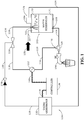
- FIG. 1 An exemplary embodiment of the invention is depicted in FIG. 1 wherein volume of water 101 is contained within the water reservoir 102 of a water cooler.
- an upper reservoir chamber 103 is defined, and typically contains gas, such as air.
- the water reservoir may be from any of the water cooler configurations generally discussed in connection with FIGS. 2A-C , or other similar water dispensers that utilize a water reservoir.
- the water reservoir 102 receives water from a water source 105 and a water inlet connection 107 and could, for instance, be a water bottle or container, the outlet of a pump, from direct connection to plumbing, or any known manner of supplying water to a water dispensing system.
- An air vent 104 is coupled to the top of the water reservoir 102 and allows air to enter or escape the reservoir 102 as water is dispensed from and refills the reservoir 102.
- a water tap, dispenser or spigot 106 draws water from the reservoir 102 directly at a water outlet connection 109 , or indirectly through a water outlet 108 connected to the water outlet connection 109 , as shown in FIG. 1 .
- Water taps are typically hot and cold outlets on water coolers such as those shown in FIGS. 2A-C , but need not be limited in function as the present invention is useful for cleaning and purifying water systems regardless of their function.
- a water reservoir may have multiple water outlets or water outlet connections for varying purposes and, as will be further described in more detail below, the proximal end of the water ozonation loop may be coupled to any existing water outlet or water outlet connection, or it may connect to a corresponding dedicated water outlet.
- a water outlet as used herein generally refers to any pathway through which water exits the water reservoir.
- a water ozonation loop 110 circulates water from the reservoir 102 via a circulating water pump 112 through a venturi tube 114 and deposits the water back into the reservoir 102.
- the water ozonation loop 110 connects the water reservoir 102 , circulating pump 112 , and venturi tube 114 together in a loop using a circulating water line 116.
- the proximal end 118 of the water line 116 receives water from the reservoir 102 and is shown in FIG. 1 connected to the water outlet 108 at a tee fitting 120. It is preferred that the proximal end 118 of the water line 116 be connected as close to the water taps 106 in series as practicable.
- Circulating ozonated water will cleanse and sanitize the maximum amount of a water cooler system's internal waterway area if the water from the reservoir 102 travels as near to the water outlet 106 as possible.
- the proximal end 118 of the water line 116 may be placed in any appropriate receiving connectivity with the water in the reservoir 102 , either directly or indirectly.
- the ozonated water circulating through the water ozonation loop 110 is then returned to the water reservoir for mixing and further sanitation at the distal end 122 of the water line 116.
- an ozone feed loop 124 is used to draw air, ozone, or a mix thereof from the upper reservoir chamber 103 into the proximal end 126 of an ozone feed line 128 and to the distal end 130 of the line 128 through an ozone generator 132.
- the proximal end 126 of the line 128 may be optionally placed in receiving connection with the upper reservoir chamber 103 via a tee fitting in the air vent 104.
- the tee fitting prevents or reduces the escape of ozone to the external environment by diverting air away from the vent 104 , thereby limiting the potential for human or animal exposure to ozone.
- the controller 136 discussed in detail below may be adapted to actuate a valve in the air vent 104 to seal off the water reservoir 102 from the external environment during an ozonation cycle.
- the proximal end 126 of the ozone feed line 128 may be appropriately coupled to the water reservoir at any upper surface of the water reservoir 102 suitable to allow the line 128 to pull the air/gas from the upper reservoir chamber 103 and into the loop 124.
- the configuration of the inlet to the ozone generator 132 in this manner permits ozone rich air that accumulates during an ozonation cycle to be recycled and circulated through the cleansing system regardless of the method used to introduce the ozone into the water.
- the distal end 130 of the ozone feed line 128 may be connected to prior art systems for introducing ozone into the water cooler, such as impeller pumps and bubblers described above.
- the ozone generator 132 Before the distal end 130 of the ozone feed line 128 terminates at the venturi 114 , it passes through an ozone generator 132 and an optional check valve 134 to prevent reverse flow or water entering into the ozone feed loop 124.
- the air, ozone or combination thereof that fills the upper reservoir chamber 103 passes through the ozone generator 132 when the ozone feed loop 124 is active, and the ozone generator 132 generates ozone thereby increasing the concentration of ozone in the line 128.
- the ozone generator may be bypassed during a portion of an ozonation cycle when ozone saturation levels are sufficient to complete the cycle without further ozone generation.
- the distal end 130 of the ozone feed line 128 is connected to the venturi tube 114 at its restricted or low-pressure flow area.
- an area of low pressure is created within the tube 114 , creating suction at the distal end 130 of the ozone feed line 128.
- the low pressure force draws the gases from the upper reservoir chamber 103 , through the ozone generator 132 , and into the water circulating in the water loop 110 via the venturi 114 , thereby imparting ozone into the water system.
- the ozone feed loop 124 imparts the ozone to the circulating water in the water loop 110 , which returns to the reservoir 102 where some ozone escapes from the now-ozonated water 101 to the upper reservoir chamber 103.
- Advantages of the present system include a more efficient ozonation system in which the flow of air and air/ozone mix through the system is created by the venturi tube effects instead of a pump or other similar device.
- the distal end 122 of the circulating water line 116 is connected to the top or near the top of the water reservoir 102 .
- Ozonated water circulating in and exiting from loop 110 is dispelled into the reservoir 102.
- Some of the ozone imparted to the circulating water in the water loop 110 escapes into the upper reservoir chamber 103 , while the rest of the ozone is carried by the water exiting the distal end 122 of the water line 116 into the volume of water 101 contained in the reservoir 102.
- the circulating water pump 112 is activated, the ozonated water is again carried through the system, cleansing the surfaces with which it comes in contact.
- the ozone generator 132 With both the ozone generator 132 and circulating water pump 112 activated, a significant amount of residual ozone will accumulate in the upper reservoir chamber 103 in a relatively short time. At an interval selectable by those skilled in the art that will vary depending upon the exact application and water system characteristics, the ozone generator 132 may be deactivated, and the gases in the closed system will continue to circulate through the ozone feed loop 124. After a time, the ozone levels will have dissipated to negligible levels, the circulating water pump 112 may be deactivated, and the ozonation cycle is complete.
- the present invention promotes longevity in ozone generator system elements in that for any given ozonation/cleansing cycle the recirculation of air in the cooler system results in a diminished need for ozone generation relative to comparable cycles of prior art systems. This in turn results in shorter run times for the generators during any given time period. Furthermore, the present invention reduces energy consumption over the life of the machine by maximizing the surface area contacted by ozonated water and reducing the length of time needed for ozone generation during ozonation cycles.
- a controller 136 is shown communicatively coupled to the ozone generator 132 via 138 and to the circulating water pump 112 via 140.
- the controller can be embodied in any form known to those skilled in the art of water cooler design, such as by way of printed circuit board (PCB) utilizing hardware, firmware, software, or other similar methods.
- the controller 136 may optionally be connected to a user interface (not shown) so that users of the water coolers applying the teachings disclosed herein may input parameters to the controller 136 to customize, for instance, the length of an ozonation cycle, its periodic timing, and the ratio of the ozone generation interval to water circulation time.
- the controller 136 activates and deactivates the ozone generator 132 and circulating water pump 112. To start a typical ozonation cycle, it is preferable that the controller 136 sends activation signals to actuate both the generator 132 and the pump 112. The controller times the elapsed run time during the ozonation cycle, and at a predetermined ozone generation interval selectable by a user, deactivates the ozone generator 132. At a second selectable interval, preferably equal to the cycle interval the controller 136 deactivates the circulating water pump 112 , the timer is reset and the ozonation cycle is complete.
- the controller 136 may be used to initiate an ozonation cycle at periodic intervals, for instance every evening or early morning when a desire to use the water cooler will be unlikely.
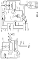
- FIGS. 2A-C are examples of configurations that are common in the art.
- FIG. 2A is an example of a bottom load cooler configuration, in which the water source is a bottle or other similar container 212 located below the water reservoir.
- FIG. 2B is an example of a design configuration commonly referred to as a top load cooler, in which the water source is a bottle or other similar container 222 located above the water reservoir.
- Water dispensers that fall into the top load category as shown in FIG. 2B typically utilize gravity to transfer water from the water source to the water reservoir, whereas bottom load dispensers as in FIG. 2A typically pump the water from the water source to the water reservoir.
- Plumbed water cooler units draw directly from a plumbing source to provide water to the water reservoir.
- the containers 212 and 222 and the plumbing source connections 232 are analogous to the water source 105 represented in FIG. 1 .
- FIG. 3 is a schematic diagram view of a water ozonation loop of a second exemplary embodiment of the invention adapted for further improvement upon bottom load cooler configurations.
- the water source 105 in a bottom load cooler is situated below the water reservoir 102 , and a water pump 312 is used to pull water through water line 116 and ultimately deliver it into the reservoir 102.
- a float 350 or other comparable sensor is used to monitor the water level 352 in the water reservoir.
- the float 350 has a low setting and a high setting that trigger the actuation and deactivation of the water pump 312 , respectively.
- the manner in which the water from the water source 105 is delivered to the water inlet connection 107 is not limited to any particular configuration.
- the water source 105 could be a top load, bottom load or plumbed cooler configuration.
- the embodiment disclosed in connection with FIG. 1 requires two water pumps (a circulating water pump and a water delivery pump) when the ozonation system is added to an existing design.
- the ozonation system uses a water pump 312 to perform both functions.
- This embodiment is also provided with an overflow fitting 354 and an overflow line 356 that provides an additional connection between the water reservoir 102 and the water source 105.
- the overflow fitting 354 is an outlet near the top of the water reservoir 102. It should be positioned in such a manner that when the water reservoir 102 is filled past the high setting on the float 350 , the water will flow out of the water reservoir 102 , through the overflow fitting 354 and overflow line 356 , and return back to the water source 105.
- the overflow line 356 be constructed of 3/8 inch inner diameter tubing for fast drainage during an ozonation cycle.
- the controller (not shown) may be adapted - as in FIG. 1 - to coordinate an ozonation cycle for a cycle interval at preset times.
- the feedback from the float 350 is utilized to determine when to actuate the pump 312 and refill the water reservoir 102 with water from the water source 105. After the water reservoir 102 is refilled, the water pump 312 is deactivated.
- the feedback from the float 350 is ignored.
- the water pump 312 and ozone generator (not shown) are actuated to begin the ozonation process.
- Water from the water source 105 is pumped through the venturi 114 wherein ozone is imparted to the water, then through the water inlet connection 107 and into the water reservoir 102.
- the water level 352 in the water reservoir 102 will continue rising - preferably beyond the high setting of the float 350 - until it reaches level with the overflow fitting 354 , whereafter the water returns to the water source 105 through the overflow line 356.
- the controller preferably deactivates the ozone generator after an ozone generation interval selected so that sufficiently high ozone concentration levels are reached within the system to adequately sanitize the interior surfaces of the waterways therein based upon the characteristics of the water system and the periodic cycling scheme of the ozonation system.
- the water pump 312 then preferably continues to circulate the water through the ozonation cycle, thereby sanitizing the lines, reservoir and water source 105.
- FIG. 4 is a schematic diagram view of a water ozonation loop 110 of a third exemplary embodiment of the invention in which a water pump 312 of a bottom load cooler serves as both a water delivery pump as well as a circulating water pump, as in FIG. 3 , but further includes an integral valve 460 joining the water ozonation loop 110 to the water outlet 108.
- the connection between a first inlet 462 of the valve 460 and the water outlet 108 can be, for instance, via the tee fitting 120 and a length of connecting piping 464 , or alternatively by direct connection.
- a second inlet 465 on the integral valve 460 is connected to the water source 105 , and an outlet in the valve 460 leads to the water pump 312.
- the bottom load cooler system is generally provided with a water reservoir 102 having a float 350 and water inlet connection 107.
- a circulating water line 116 leads from the valve 460 and through the water pump 312 and venturi 114 to return water to the water inlet connection 107 during an ozonation cycle or to replenish the water reservoir 102 with water from the water source 105.
- the venturi 114 may optionally be configured with a bypass for use during replenishment cycles.
- the integral valve 460 has a first state and a second state, and selecting and switching between the appropriate state may be handled by the controller (not shown) adapted for such purposes.
- the integral valve 460 be embodied as a three way solenoid valve wherein the controller actuates the solenoid to change between the states.
- Other comparable methods of controlling, operating, and constructing the valve will be evident to those skilled in art and are considered to be included as equivalents herein.
- the first inlet 462 In the first state (i.e., normal bottom load cooler operation), the first inlet 462 is closed and the second inlet 465 is open, and operation of the water pump 312 transfers water from the water tank 105 to the water reservoir 102.
- the second state In the second state, the first inlet 462 is open and the second inlet 465 is closed, and operation of the water pump 312 circulates water from the water reservoir 102 through the water outlet 108 , through the venturi 114 wherein ozone is imparted to the circulating water (the ozone feed loop not shown for purposes of clarity and brevity), and back into the water reservoir 102.
- This embodiment has the advantage of allowing the maximum surface area of the internal waterways (e.g., up to the tee fitting 120 near the water tap 106 ), as well as energy savings resulting from the combined pumping functions performed by the water pump 312.
- the controller (not shown in FIG. 4 ) is adapted for switching the integral valve to the second state from the first (default) state and actuating the circulating water pump and the ozone generator to implement an ozonation cycle.
- the ozonation cycle is completed after a selectable cycle interval.
- the controller actuates the water pump for the entire cycle interval and the ozone generator during an ozone generation interval wherein the ozone generation interval is less than the cycle interval.
- FIG. 5 is a schematic diagram view of a water ozonation loop of a fourth exemplary embodiment of the invention. This embodiment is identical to the embodiment shown in connection with FIG. 4 , with the exception of the water source 105.
- the water source 105 is a plumbed line that passes through an optional filtration system 570 , for instance, which are commonly present in plumbed cooler system configurations.
- the water pump 312 in the water ozonation loop 110 circulates water from the water reservoir 102 through a water outlet 108 , for example at a tee fitting 120 located near the water tap 106 , through the first inlet 462 of the integral valve 460 , the venturi 114 of the ozone feed loop (not shown) and into the water reservoir 102 through the water inlet connection 107.
- FIG. 6 is a schematic diagram view of a fifth exemplary embodiment of the invention combining the features shown and described in connection with FIGS. 3 and 4 for a bottom load cooler configuration.
- an integral valve 460 for instance, an overflow fitting 354 and overflow line 356 are present.
- the advantages of the embodiment are in part the energy savings arising from the use of a single water pump 312 , as well as the ability to sanitize the largest amount of inner waterway surfaces for bottom load configurations.
- the controller 136 coordinates the actuation and monitoring of the ozone generator 132 , the water pump 312 , the integral valve 460 , and the float 350 to enable at least three ozonation system states: a normal (default) state, a first ozonation state and a second ozonation state.
- the integral valve 460 is in the first state wherein the first inlet 462 is closed and the second inlet 465 is open.
- the controller actuates the water pump 312 , deactivating it when the high setting on the float 350 is indicated.
- the circulating water line 116 , water reservoir 102 and water outlet 108 are all sanitized, as well as any other inner waterway surfaces encountered by the circulating water in the water ozonation loop 110.
- the controller 136 switches the integral valve 460 to its second state, opening the first inlet 462 and closing the second inlet 465.
- the water pump 312 and ozone generator 132 are actuated, and water circulates in the water ozonation loop 110 and air/ozone circulates in the ozone feed loop 124 via an ozone feed line 128 as previously described herein.
- the controller 136 deactivates the ozone generator 132 , and the water pump 312 continues to circulate water until a selectable cycle interval has been reached.
- a second ozonation state is available in which the water source 105 is included in the water ozonation loop 110.
- the controller 136 ensures that the integral valve 460 is in its first state, with a closed first inlet 462 and an open second inlet 465.
- the feedback from the float 350 is ignored by the controller 136 , and the circulating water pump 312 and ozone generator 132 are actuated.
- the water reservoir 102 is filled with water transferred from the water source 105 until it begins to overflow through the overflow fitting 354 - and overflow line 356 connected thereto - into the water source 105 .
- the ozone feed loop 124 is imparting ozone into the water in the water ozonation loop 110 at the venturi 114 , until the ozone generation interval is reached, at which time the controller 136 deactivates the ozone generator 132.
- the water pump 312 continues to circulate the ozonated water until the cycle interval is completed, and the ozone has been safely depleted during the sanitization process. Note that, during "overflow" (i.e., the second) ozonation of the water source 105 as described in this paragraph and in connection with FIG.
- the ozone generator 132 is deactivated when the controller 136 detects an increase in power to the ozone generator 132.
- first and second ozonation states need not be mutually exclusive in the sense that they may both occur as part of a predetermined ozonation cycle. That is, an ozonation cycle may be coordinated in which one of the first and second ozonation states is entered at the beginning of the ozonation cycle, after which the controller switches to the second state to ozonate all waterways, and the ozone generation interval may be selected to fall in the first or second segment of the ozonation cycle.
- the first and second ozonation states could be utilized independently at periodic intervals, for example, the first state every other day during early morning hours, and the second state on days in between.
- any embodiment of the disclosed system and method may include any of the optional or preferred features of the other embodiments of the present invention.
- the exemplary embodiments herein disclosed are not intended to be exhaustive or to unnecessarily limit the scope of the invention.
- the exemplary embodiments were chosen and described in order to explain the principles of the present invention so that others skilled in the art may practice the invention. Having shown and described exemplary embodiments of the present invention, those skilled in the art will realize that many variations and modifications may be made to affect the described invention that are within the scope of the appended claims. It is the intention, therefore, to limit the invention only as indicated by the scope of the claims.
Landscapes
- Life Sciences & Earth Sciences (AREA)
- Hydrology & Water Resources (AREA)
- Engineering & Computer Science (AREA)
- Environmental & Geological Engineering (AREA)
- Water Supply & Treatment (AREA)
- Chemical & Material Sciences (AREA)
- Organic Chemistry (AREA)
- Treatment Of Water By Oxidation Or Reduction (AREA)
- Domestic Plumbing Installations (AREA)
- Apparatus For Disinfection Or Sterilisation (AREA)
Claims (13)
- Appareil destiné à distribuer de l'eau assainie à partir d'une source d'eau, comprenant :
un réservoir d'eau (102) ayant un volume total, destiné à contenir un volume d'eau (101), le réservoir d'eau (102) comprenant :un raccord d'admission d'eau (107) adapté pour coupler le réservoir d'eau (102) à la source d'eau (105) ;une chambre de réservoir supérieure (103) ayant un volume défini par la différence entre le volume total du réservoir d'eau et le volume de l'eau contenue à l'intérieur (101), dans lequel le volume de la chambre de réservoir supérieure (103) contient de l'air ; etun raccord d'évacuation d'eau (109) qui couple le réservoir d'eau (102) à une évacuation d'eau (108) ;une boucle d'ozonation de l'eau (110) destinée à faire circuler au moins une partie du volume d'eau (101) hors du réservoir d'eau (102), par le biais de l'évacuation d'eau (108), vers la chambre de réservoir supérieure (103), la boucle d'ozonation de l'eau (110) comprenant :une conduite d'eau en circulation (116) ayant une première extrémité (118) couplée à l'évacuation d'eau (108) et une seconde extrémité (122) couplée à la chambre de réservoir supérieure (103) ;une pompe en ligne (112) destinée à faire circuler l'eau dans la conduite d'eau en circulation (116) ; etun tube de Venturi en ligne (114) ;un générateur d'ozone (132) ; etun moyen d'alimentation en ozone (124) prévu pour distribuer de l'ozone, depuis le générateur d'ozone (132), au volume d'eau (101) en circulation dans la boucle d'ozonation de l'eau (110), le moyen d'alimentation en ozone (124) comprenant une conduite d'alimentation en ozone (128) ayant une première extrémité (126) reliée à la chambre de réservoir supérieure (103) et une seconde extrémité (130) reliée au tube de Venturi (114), avec le générateur d'ozone (132) prévu dans la conduite d'alimentation en ozone (128) afin de recevoir l'air aspiré depuis la chambre de réservoir supérieure (103), de générer de l'ozone à partir de l'oxygène contenu dans l'air aspiré et d'injecter l'ozone généré dans l'eau qui circule dans la conduite d'eau en circulation (116) au niveau du tube de Venturi (114). - Appareil d'assainissement de l'eau selon la revendication 1, comprenant en outre :un dispositif de trop-plein (354) sur le réservoir d'eau (102) ; etun conduite de trop-plein (356) qui relie le dispositif de trop-plein (354) à la source d'eau (105).
- Appareil d'assainissement de l'eau selon la revendication 1 ou 2, comprenant en outre :
une vanne intégrale (460) adaptée pour basculer entre un premier état et un second état, la vanne intégrale (460) comprenant :une première admission (462) qui relie la vanne intégrale (460) à l'évacuation d'eau (108), dans lequel la première admission (462) est fermée dans le premier état et ouverte dans le second état ;une seconde admission (465) qui relie la vanne intégrale (460) à la source d'eau (105), dans lequel la seconde admission (465) est ouverte dans le premier état et fermée dans le second état ; etune évacuation ouverte dans le premier et le second états,dans lequel la première extrémité de la conduite d'eau en circulation (116) est couplée à l'évacuation de la vanne intégrale (460) et la seconde extrémité de la conduite d'eau en circulation est couplée à l'admission d'eau,dans lequel le réservoir d'eau (102) comprend en outre un évent (104),dans lequel l'extrémité proximale (126) de la conduite d'alimentation en ozone (128) est couplée à l'évent (104), etdans lequel le fonctionnement simultané de la pompe à eau en circulation (112) et du générateur d'ozone (132) fait circuler un flux d'eau depuis la vanne intégrale (460), par le biais de la boucle d'ozonation de l'eau (110), afin d'aspirer un flux d'ozone du générateur d'ozone (132) vers la boucle d'ozonation de l'eau (110). - Appareil d'assainissement de l'eau selon la revendication 3, comprenant en outre un contrôleur (136) adapté pour faire passer la vanne intégrale (460) dans le second état et pour déclencher la pompe à eau en circulation (112) et le générateur d'ozone (132) de façon à mettre en œuvre un cycle d'ozonation pendant un intervalle de cycle.
- Appareil d'assainissement de l'eau selon la revendication 4, dans lequel le contrôleur (136) est en outre adapté pour déclencher la pompe en ligne (112) pendant l'intervalle de cycle, et pour déclencher le générateur d'ozone (132) pendant un intervalle de génération d'ozone, dans lequel l'intervalle de génération d'ozone (132) est inférieur à l'intervalle de cycle.
- Appareil d'assainissement de l'eau selon les revendications 1 ou 2, comprenant en outre un contrôleur (136) adapté pour déclencher la pompe en ligne (112) et le générateur d'ozone (132) afin de mettre en œuvre un cycle d'ozonation pendant un intervalle de cycle.
- Appareil d'assainissement de l'eau selon la revendication 6, dans lequel le contrôleur (136) est adapté pour déclencher la pompe en ligne (112) pendant l'intervalle de cycle, et pour déclencher le générateur d'ozone (132) pendant un intervalle de génération d'ozone, dans lequel l'intervalle de génération d'ozone (132) est inférieur à l'intervalle de cycle.
- Appareil d'assainissement de l'eau selon la revendication 5 ou 7, dans lequel l'intervalle de génération d'ozone est inférieur ou égal à 10% de l'intervalle de cycle.
- Appareil d'assainissement de l'eau selon l'une quelconque des revendications précédentes, comprenant en outre un clapet anti-retour (134) positionné sur le moyen d'alimentation en ozone (124) afin d'empêcher tout flux d'eau vers le générateur d'ozone (132).
- Procédé de distribution d'eau assainie depuis une source d'eau, le procédé comprenant les étapes consistant à :prévoir l'appareil selon la revendication 1, le réservoir d'eau (102) contenant un volume d'eau (101) ;faire circuler au moins une partie du volume d'eau (101) hors du réservoir d'eau (102) par le biais de l'évacuation d'eau (108), vers la chambre de réservoir supérieure (103) ; etdistribuer l'ozone qui provient du générateur d'ozone (132) au volume d'eau (101) en circulation dans la boucle d'ozonation de l'eau (110).
- Procédé selon la revendication 10, comprenant en outre l'étape de programmation d'un contrôleur (136) afin de mettre en œuvre un cycle d'ozonation qui peut être activé par le contrôleur (136), moyennant quoi le contrôleur (136) active la pompe à eau en ligne (112) et le générateur d'ozone (132) pendant le cycle d'ozonation afin de faire circuler un flux d'eau depuis le réservoir d'eau (102), par le biais de la boucle d'ozonation de l'eau (110), de façon à aspirer un flux d'ozone du générateur d'ozone (132) vers la boucle d'ozonation de l'eau (110).
- Procédé selon la revendication 11, le procédé comprenant en outre l'étape qui consiste à mettre fin au cycle d'ozonation après un premier intervalle de temps sélectionnable à l'aide d'un minuteur associé au contrôleur (136) .
- Procédé selon la revendication 11, comprenant en outre l'étape de programmation du contrôleur (136) afin d'activer la pompe à eau en circulation (112) et le générateur d'ozone (132) lorsque le cycle d'ozonation est activé, de désactiver le générateur d'ozone (132) au bout d'une première durée sélectionnable, et de désactiver la pompe à eau en circulation (112) au bout d'une seconde durée sélectionnable, dans lequel la seconde durée sélectionnable coïncide avec la fin du cycle d'ozonation.
Applications Claiming Priority (3)
| Application Number | Priority Date | Filing Date | Title |
|---|---|---|---|
| US201361832193P | 2013-06-07 | 2013-06-07 | |
| US201461930659P | 2014-01-23 | 2014-01-23 | |
| PCT/US2014/041219 WO2014197759A1 (fr) | 2013-06-07 | 2014-06-06 | Dispositif et procédé de désinfection de surfaces et de traitement d'eau a l'aide d'ozone |
Publications (3)
| Publication Number | Publication Date |
|---|---|
| EP3003534A1 EP3003534A1 (fr) | 2016-04-13 |
| EP3003534A4 EP3003534A4 (fr) | 2017-01-25 |
| EP3003534B1 true EP3003534B1 (fr) | 2020-03-18 |
Family
ID=52004572
Family Applications (1)
| Application Number | Title | Priority Date | Filing Date |
|---|---|---|---|
| EP14806926.3A Active EP3003534B1 (fr) | 2013-06-07 | 2014-06-06 | Dispositif et procédé de traitement d'eau a l'aide d'ozone |
Country Status (5)
| Country | Link |
|---|---|
| US (1) | US9969632B2 (fr) |
| EP (1) | EP3003534B1 (fr) |
| JP (1) | JP6397003B2 (fr) |
| CN (1) | CN105451858A (fr) |
| WO (1) | WO2014197759A1 (fr) |
Families Citing this family (5)
| Publication number | Priority date | Publication date | Assignee | Title |
|---|---|---|---|---|
| CN108328578B (zh) * | 2018-01-29 | 2020-03-10 | 荣成海奥斯生物科技有限公司 | 气态有效氯水溶液的灌装装置 |
| US11034594B2 (en) | 2018-08-10 | 2021-06-15 | Ds Services Of America, Inc. | Top fill reservoir system for water purification system |
| CN109965707B (zh) * | 2019-04-03 | 2024-02-20 | 中山活水来智慧物联网有限责任公司 | 一种具有消毒功能的储水式饮水机及其消毒方法 |
| US11278636B2 (en) * | 2020-07-21 | 2022-03-22 | Blue Penny LLC | Ozone disinfecting system and devices configured to convert water into ozone for disinfecting, cleaning, or sanitizing |
| JP2022076533A (ja) * | 2020-11-10 | 2022-05-20 | 株式会社ヤマト | 細菌抑制装置及び給水装置 |
Family Cites Families (45)
| Publication number | Priority date | Publication date | Assignee | Title |
|---|---|---|---|---|
| US4619763A (en) | 1983-07-21 | 1986-10-28 | Brien Edward J O | Ozone H2 O treatment |
| JPS61130400U (fr) * | 1985-01-28 | 1986-08-15 | ||
| JPS6476860A (en) * | 1987-09-17 | 1989-03-22 | Sanyo Electric Co | Sterilizing apparatus |
| JPS6448196U (fr) * | 1987-09-18 | 1989-03-24 | ||
| US4842723A (en) * | 1987-12-17 | 1989-06-27 | Bowman, Mell Company, Inc. | Water purifying apparatus |
| JPH01275402A (ja) * | 1988-04-27 | 1989-11-06 | Nippon Sanso Kk | 酸素リサイクル式オゾナイザシステム |
| US5207993A (en) * | 1990-08-31 | 1993-05-04 | Burris William A | Batch liquid purifier |
| JPH0679256A (ja) * | 1992-09-02 | 1994-03-22 | Sanden Corp | 浄水システム |
| US5368815A (en) * | 1992-12-07 | 1994-11-29 | Oxidyn, Incorporated | Process and apparatus for sanitizing articles |
| JPH078976A (ja) * | 1993-06-28 | 1995-01-13 | Meidensha Corp | オゾン処理装置 |
| US5897832A (en) | 1996-04-30 | 1999-04-27 | Porter; Brooks S. | Cleaning method utilizing ozonated water and apparatus for producing ozonated water |
| US5824243A (en) | 1997-02-12 | 1998-10-20 | Contreras; Edward M. | Water ozonating system |
| US6200473B1 (en) * | 1998-11-06 | 2001-03-13 | G. Scott Fahey | In-transit water treatment system |
| US7748233B2 (en) | 1998-12-23 | 2010-07-06 | S.I.P. Technologies L.L.C. | Sanitized water dispenser |
| US6085540A (en) | 1998-12-23 | 2000-07-11 | Davis; Kenneth A. | Method and apparatus for disinfecting a water cooler reservoir |
| US7175054B2 (en) | 1998-12-23 | 2007-02-13 | S.I.P. Technologies, Llc | Method and apparatus for disinfecting a refrigerated water cooler reservoir |
| US6532760B2 (en) | 1998-12-23 | 2003-03-18 | S.I.P. Technologies, L.L.C. | Method and apparatus for disinfecting a water cooler reservoir |
| US6561382B2 (en) | 2001-06-15 | 2003-05-13 | S.I.P. Technologies, L.L.C. | Method and apparatus for disinfecting a water cooler reservoir and its dispensing spigot(s) |
| JP2001000986A (ja) * | 1999-06-24 | 2001-01-09 | Hitachi Ltd | オゾン注入システム |
| JP2001070962A (ja) * | 1999-09-01 | 2001-03-21 | Ebara Corp | 難分解性物質分解装置 |
| SE0000344D0 (sv) * | 2000-02-02 | 2000-02-02 | Sudhir Chowdhury | Disinfection of water |
| AU2002359272A1 (en) | 2001-10-15 | 2003-04-28 | Pure O3 Tech, Inc. | Dissolved ozone generation and delivery system |
| US7425301B2 (en) | 2001-11-26 | 2008-09-16 | Fresh Food Technology, Inc. | Method for providing ozone sanitation of fruits and vegetables |
| US8366920B2 (en) | 2002-06-17 | 2013-02-05 | S.I.P. Technologies L.L.C. | Method and apparatus for programably treating water in a water cooler |
| US7640766B2 (en) | 2002-06-17 | 2010-01-05 | S.I.P. Technologies L.L.C. | Method and apparatus for disinfecting a refrigerated water cooler reservoir |
| JP4088165B2 (ja) * | 2003-01-27 | 2008-05-21 | 大明株式会社 | 空気調和用冷却水循環系の浄化装置 |
| JP4271991B2 (ja) * | 2003-05-26 | 2009-06-03 | オリエンタル機電株式会社 | オゾン水処理装置 |
| JP2005021798A (ja) | 2003-07-01 | 2005-01-27 | Teeiku Wan Sogo Jimusho:Kk | オゾン水製造方法、オゾン水製造装置 |
| US7422684B1 (en) | 2003-10-16 | 2008-09-09 | S.I.P. Technologies, L.L.C. | Method and apparatus for sanitizing water dispensed from a water dispenser having a reservoir |
| US7258803B2 (en) | 2004-04-21 | 2007-08-21 | S.I.P. Technologies L.L.C. | Method and apparatus for programably treating water in a water cooler |
| US7114637B2 (en) | 2004-04-21 | 2006-10-03 | Davis Kenneth A | Method and apparatus for programably treating water in a water cooler |
| WO2006010109A2 (fr) * | 2004-07-08 | 2006-01-26 | Akrion Technologies, Inc. | Procede et appareil permettant de creer des solutions de traitement ozonisees possedant une concentration elevee d'ozone |
| JP4971638B2 (ja) * | 2006-01-13 | 2012-07-11 | 三洋電機株式会社 | 水供給システムおよび水供給システム用の水質改善装置 |
| CN2934225Y (zh) * | 2006-11-07 | 2007-08-15 | 梁绍林 | 健浴污水循环净化设备 |
| JP2007275893A (ja) * | 2007-06-20 | 2007-10-25 | Eiji Matsumura | 気体混合液生成方法及び気体混合液 |
| JP4854623B2 (ja) * | 2007-07-30 | 2012-01-18 | 三洋電機株式会社 | 水処理システム |
| JP5056251B2 (ja) * | 2007-08-07 | 2012-10-24 | 株式会社Ihi | オゾン水応用機器及びそのカビ防止方法 |
| NZ584768A (en) * | 2007-09-21 | 2011-11-25 | Reclaim Water Pty Ltd | Hyperoxidation advanced oxidative treatment of water |
| JP2012512012A (ja) * | 2008-12-16 | 2012-05-31 | オキシ ソリューションズ エーエス | 流体の酸素化における改良 |
| JP2011240206A (ja) * | 2010-05-14 | 2011-12-01 | Maindorei Gijutsu Kagaku Kenkyusho:Kk | オゾン微小気泡含有水製造装置、オゾン微小気泡含有水製造方法、物品洗浄装置、物品洗浄方法、水産物の養殖方法及び水耕栽培方法 |
| JP5749521B2 (ja) * | 2011-03-01 | 2015-07-15 | エア・ウォーター株式会社 | 廃水処理装置および方法 |
| JP5079896B2 (ja) * | 2011-03-18 | 2012-11-21 | シャープ株式会社 | オゾン液生成器及びその生成方法 |
| JP2013010068A (ja) * | 2011-06-29 | 2013-01-17 | Sharp Corp | オゾン液生成器及びオゾン液生成方法 |
| JP2013094696A (ja) * | 2011-10-28 | 2013-05-20 | Sharp Corp | 溶解液生成装置およびオゾン水生成装置、並びに、それを備えた衛生器具用洗浄装置 |
| US20130341285A1 (en) * | 2012-06-26 | 2013-12-26 | Chadwick D. Marion | Assuring threshold ozone concentration in water delivered to an exit point |
-
2014
- 2014-06-06 EP EP14806926.3A patent/EP3003534B1/fr active Active
- 2014-06-06 US US14/297,706 patent/US9969632B2/en active Active
- 2014-06-06 JP JP2016518020A patent/JP6397003B2/ja active Active
- 2014-06-06 WO PCT/US2014/041219 patent/WO2014197759A1/fr active Application Filing
- 2014-06-06 CN CN201480044361.4A patent/CN105451858A/zh active Pending
Non-Patent Citations (1)
| Title |
|---|
| None * |
Also Published As
| Publication number | Publication date |
|---|---|
| JP6397003B2 (ja) | 2018-09-26 |
| JP2016525939A (ja) | 2016-09-01 |
| US9969632B2 (en) | 2018-05-15 |
| EP3003534A1 (fr) | 2016-04-13 |
| WO2014197759A1 (fr) | 2014-12-11 |
| EP3003534A4 (fr) | 2017-01-25 |
| CN105451858A (zh) | 2016-03-30 |
| US20140360948A1 (en) | 2014-12-11 |
Similar Documents
| Publication | Publication Date | Title |
|---|---|---|
| EP3003534B1 (fr) | Dispositif et procédé de traitement d'eau a l'aide d'ozone | |
| US7875173B1 (en) | Ozone generator retrofit apparatus for jetted tubs, spas, and other water circulation facilities | |
| EP1852131B1 (fr) | Distributeur d'eau avec un circuit de désinfection | |
| EP2797835B1 (fr) | Distributeur d'eau équipé d'un mécanisme de nettoyage | |
| US11045829B2 (en) | Self-sealing shower head with disinfectant | |
| EP2670713A1 (fr) | Système de traitement de l'eau | |
| US20160023880A1 (en) | Beverage dispenser and method for sanitation thereof | |
| EP3269885B1 (fr) | Dispositif de nettoyage d'un nouveau type et procédé de nettoyage associé | |
| CN108431339A (zh) | 自清洗马桶组件和系统 | |
| US10071402B2 (en) | Method for sterilizing water treatment apparatus having plurality of tanks | |
| US20150251921A1 (en) | Food waste collector system with treatment of recirculating water to reduce bacteria levels | |
| CN108236565B (zh) | 水疗设备及该水疗设备的消毒方法 | |
| JP2006116288A (ja) | 炭酸含有加熱水生成方法及び装置 | |
| KR101733429B1 (ko) | 치과 진료수 생성장치 | |
| JPH10263555A (ja) | 浴水循環浄化装置 | |
| CN109528381B (zh) | 护理机 | |
| CN219471129U (zh) | 一种智能盖板管路系统 | |
| TWI767230B (zh) | 具有消毒液濃度偵測功能之消毒設備 | |
| JP4854952B2 (ja) | 内視鏡洗浄装置 | |
| JPH10263556A (ja) | 循環浄化装置 | |
| CN108143290B (zh) | 烹饪设备 | |
| JP3050891B2 (ja) | 浴槽水浄化フイルタの殺菌方法およびその装置 | |
| CN116458769A (zh) | 高温消毒饮水机及其消毒方法与温水加热方法 | |
| JP2000301159A (ja) | 殺菌・抗菌装置 | |
| JPH10296267A (ja) | 循環浄化装置 |
Legal Events
| Date | Code | Title | Description |
|---|---|---|---|
| PUAI | Public reference made under article 153(3) epc to a published international application that has entered the european phase |
Free format text: ORIGINAL CODE: 0009012 |
|
| 17P | Request for examination filed |
Effective date: 20160107 |
|
| AK | Designated contracting states |
Kind code of ref document: A1 Designated state(s): AL AT BE BG CH CY CZ DE DK EE ES FI FR GB GR HR HU IE IS IT LI LT LU LV MC MK MT NL NO PL PT RO RS SE SI SK SM TR |
|
| AX | Request for extension of the european patent |
Extension state: BA ME |
|
| DAX | Request for extension of the european patent (deleted) | ||
| A4 | Supplementary search report drawn up and despatched |
Effective date: 20161223 |
|
| RIC1 | Information provided on ipc code assigned before grant |
Ipc: C02F 1/78 20060101ALI20161219BHEP Ipc: B01D 47/10 20060101AFI20161219BHEP Ipc: B01F 5/06 20060101ALI20161219BHEP |
|
| STAA | Information on the status of an ep patent application or granted ep patent |
Free format text: STATUS: EXAMINATION IS IN PROGRESS |
|
| 17Q | First examination report despatched |
Effective date: 20171128 |
|
| GRAP | Despatch of communication of intention to grant a patent |
Free format text: ORIGINAL CODE: EPIDOSNIGR1 |
|
| STAA | Information on the status of an ep patent application or granted ep patent |
Free format text: STATUS: GRANT OF PATENT IS INTENDED |
|
| GRAJ | Information related to disapproval of communication of intention to grant by the applicant or resumption of examination proceedings by the epo deleted |
Free format text: ORIGINAL CODE: EPIDOSDIGR1 |
|
| STAA | Information on the status of an ep patent application or granted ep patent |
Free format text: STATUS: EXAMINATION IS IN PROGRESS |
|
| INTG | Intention to grant announced |
Effective date: 20190919 |
|
| GRAP | Despatch of communication of intention to grant a patent |
Free format text: ORIGINAL CODE: EPIDOSNIGR1 |
|
| STAA | Information on the status of an ep patent application or granted ep patent |
Free format text: STATUS: GRANT OF PATENT IS INTENDED |
|
| INTC | Intention to grant announced (deleted) | ||
| INTG | Intention to grant announced |
Effective date: 20191022 |
|
| GRAS | Grant fee paid |
Free format text: ORIGINAL CODE: EPIDOSNIGR3 |
|
| GRAA | (expected) grant |
Free format text: ORIGINAL CODE: 0009210 |
|
| STAA | Information on the status of an ep patent application or granted ep patent |
Free format text: STATUS: THE PATENT HAS BEEN GRANTED |
|
| AK | Designated contracting states |
Kind code of ref document: B1 Designated state(s): AL AT BE BG CH CY CZ DE DK EE ES FI FR GB GR HR HU IE IS IT LI LT LU LV MC MK MT NL NO PL PT RO RS SE SI SK SM TR |
|
| REG | Reference to a national code |
Ref country code: GB Ref legal event code: FG4D |
|
| REG | Reference to a national code |
Ref country code: DE Ref legal event code: R096 Ref document number: 602014062578 Country of ref document: DE |
|
| REG | Reference to a national code |
Ref country code: AT Ref legal event code: REF Ref document number: 1245255 Country of ref document: AT Kind code of ref document: T Effective date: 20200415 Ref country code: IE Ref legal event code: FG4D |
|
| PG25 | Lapsed in a contracting state [announced via postgrant information from national office to epo] |
Ref country code: NO Free format text: LAPSE BECAUSE OF FAILURE TO SUBMIT A TRANSLATION OF THE DESCRIPTION OR TO PAY THE FEE WITHIN THE PRESCRIBED TIME-LIMIT Effective date: 20200618 Ref country code: FI Free format text: LAPSE BECAUSE OF FAILURE TO SUBMIT A TRANSLATION OF THE DESCRIPTION OR TO PAY THE FEE WITHIN THE PRESCRIBED TIME-LIMIT Effective date: 20200318 Ref country code: RS Free format text: LAPSE BECAUSE OF FAILURE TO SUBMIT A TRANSLATION OF THE DESCRIPTION OR TO PAY THE FEE WITHIN THE PRESCRIBED TIME-LIMIT Effective date: 20200318 |
|
| REG | Reference to a national code |
Ref country code: NL Ref legal event code: MP Effective date: 20200318 |
|
| PG25 | Lapsed in a contracting state [announced via postgrant information from national office to epo] |
Ref country code: GR Free format text: LAPSE BECAUSE OF FAILURE TO SUBMIT A TRANSLATION OF THE DESCRIPTION OR TO PAY THE FEE WITHIN THE PRESCRIBED TIME-LIMIT Effective date: 20200619 Ref country code: HR Free format text: LAPSE BECAUSE OF FAILURE TO SUBMIT A TRANSLATION OF THE DESCRIPTION OR TO PAY THE FEE WITHIN THE PRESCRIBED TIME-LIMIT Effective date: 20200318 Ref country code: SE Free format text: LAPSE BECAUSE OF FAILURE TO SUBMIT A TRANSLATION OF THE DESCRIPTION OR TO PAY THE FEE WITHIN THE PRESCRIBED TIME-LIMIT Effective date: 20200318 Ref country code: LV Free format text: LAPSE BECAUSE OF FAILURE TO SUBMIT A TRANSLATION OF THE DESCRIPTION OR TO PAY THE FEE WITHIN THE PRESCRIBED TIME-LIMIT Effective date: 20200318 Ref country code: BG Free format text: LAPSE BECAUSE OF FAILURE TO SUBMIT A TRANSLATION OF THE DESCRIPTION OR TO PAY THE FEE WITHIN THE PRESCRIBED TIME-LIMIT Effective date: 20200618 |
|
| REG | Reference to a national code |
Ref country code: LT Ref legal event code: MG4D |
|
| PG25 | Lapsed in a contracting state [announced via postgrant information from national office to epo] |
Ref country code: NL Free format text: LAPSE BECAUSE OF FAILURE TO SUBMIT A TRANSLATION OF THE DESCRIPTION OR TO PAY THE FEE WITHIN THE PRESCRIBED TIME-LIMIT Effective date: 20200318 |
|
| PG25 | Lapsed in a contracting state [announced via postgrant information from national office to epo] |
Ref country code: PT Free format text: LAPSE BECAUSE OF FAILURE TO SUBMIT A TRANSLATION OF THE DESCRIPTION OR TO PAY THE FEE WITHIN THE PRESCRIBED TIME-LIMIT Effective date: 20200812 Ref country code: LT Free format text: LAPSE BECAUSE OF FAILURE TO SUBMIT A TRANSLATION OF THE DESCRIPTION OR TO PAY THE FEE WITHIN THE PRESCRIBED TIME-LIMIT Effective date: 20200318 Ref country code: EE Free format text: LAPSE BECAUSE OF FAILURE TO SUBMIT A TRANSLATION OF THE DESCRIPTION OR TO PAY THE FEE WITHIN THE PRESCRIBED TIME-LIMIT Effective date: 20200318 Ref country code: SM Free format text: LAPSE BECAUSE OF FAILURE TO SUBMIT A TRANSLATION OF THE DESCRIPTION OR TO PAY THE FEE WITHIN THE PRESCRIBED TIME-LIMIT Effective date: 20200318 Ref country code: RO Free format text: LAPSE BECAUSE OF FAILURE TO SUBMIT A TRANSLATION OF THE DESCRIPTION OR TO PAY THE FEE WITHIN THE PRESCRIBED TIME-LIMIT Effective date: 20200318 Ref country code: IS Free format text: LAPSE BECAUSE OF FAILURE TO SUBMIT A TRANSLATION OF THE DESCRIPTION OR TO PAY THE FEE WITHIN THE PRESCRIBED TIME-LIMIT Effective date: 20200718 Ref country code: CZ Free format text: LAPSE BECAUSE OF FAILURE TO SUBMIT A TRANSLATION OF THE DESCRIPTION OR TO PAY THE FEE WITHIN THE PRESCRIBED TIME-LIMIT Effective date: 20200318 Ref country code: SK Free format text: LAPSE BECAUSE OF FAILURE TO SUBMIT A TRANSLATION OF THE DESCRIPTION OR TO PAY THE FEE WITHIN THE PRESCRIBED TIME-LIMIT Effective date: 20200318 |
|
| REG | Reference to a national code |
Ref country code: AT Ref legal event code: MK05 Ref document number: 1245255 Country of ref document: AT Kind code of ref document: T Effective date: 20200318 |
|
| REG | Reference to a national code |
Ref country code: DE Ref legal event code: R097 Ref document number: 602014062578 Country of ref document: DE |
|
| REG | Reference to a national code |
Ref country code: DE Ref legal event code: R119 Ref document number: 602014062578 Country of ref document: DE |
|
| PLBE | No opposition filed within time limit |
Free format text: ORIGINAL CODE: 0009261 |
|
| STAA | Information on the status of an ep patent application or granted ep patent |
Free format text: STATUS: NO OPPOSITION FILED WITHIN TIME LIMIT |
|
| PG25 | Lapsed in a contracting state [announced via postgrant information from national office to epo] |
Ref country code: IT Free format text: LAPSE BECAUSE OF FAILURE TO SUBMIT A TRANSLATION OF THE DESCRIPTION OR TO PAY THE FEE WITHIN THE PRESCRIBED TIME-LIMIT Effective date: 20200318 Ref country code: ES Free format text: LAPSE BECAUSE OF FAILURE TO SUBMIT A TRANSLATION OF THE DESCRIPTION OR TO PAY THE FEE WITHIN THE PRESCRIBED TIME-LIMIT Effective date: 20200318 Ref country code: DK Free format text: LAPSE BECAUSE OF FAILURE TO SUBMIT A TRANSLATION OF THE DESCRIPTION OR TO PAY THE FEE WITHIN THE PRESCRIBED TIME-LIMIT Effective date: 20200318 Ref country code: AT Free format text: LAPSE BECAUSE OF FAILURE TO SUBMIT A TRANSLATION OF THE DESCRIPTION OR TO PAY THE FEE WITHIN THE PRESCRIBED TIME-LIMIT Effective date: 20200318 Ref country code: MC Free format text: LAPSE BECAUSE OF FAILURE TO SUBMIT A TRANSLATION OF THE DESCRIPTION OR TO PAY THE FEE WITHIN THE PRESCRIBED TIME-LIMIT Effective date: 20200318 |
|
| REG | Reference to a national code |
Ref country code: CH Ref legal event code: PL |
|
| 26N | No opposition filed |
Effective date: 20201221 |
|
| PG25 | Lapsed in a contracting state [announced via postgrant information from national office to epo] |
Ref country code: PL Free format text: LAPSE BECAUSE OF FAILURE TO SUBMIT A TRANSLATION OF THE DESCRIPTION OR TO PAY THE FEE WITHIN THE PRESCRIBED TIME-LIMIT Effective date: 20200318 |
|
| GBPC | Gb: european patent ceased through non-payment of renewal fee |
Effective date: 20200618 |
|
| PG25 | Lapsed in a contracting state [announced via postgrant information from national office to epo] |
Ref country code: LU Free format text: LAPSE BECAUSE OF NON-PAYMENT OF DUE FEES Effective date: 20200606 |
|
| REG | Reference to a national code |
Ref country code: BE Ref legal event code: MM Effective date: 20200630 |
|
| PG25 | Lapsed in a contracting state [announced via postgrant information from national office to epo] |
Ref country code: CH Free format text: LAPSE BECAUSE OF NON-PAYMENT OF DUE FEES Effective date: 20200630 Ref country code: IE Free format text: LAPSE BECAUSE OF NON-PAYMENT OF DUE FEES Effective date: 20200606 Ref country code: GB Free format text: LAPSE BECAUSE OF NON-PAYMENT OF DUE FEES Effective date: 20200618 Ref country code: LI Free format text: LAPSE BECAUSE OF NON-PAYMENT OF DUE FEES Effective date: 20200630 Ref country code: FR Free format text: LAPSE BECAUSE OF NON-PAYMENT OF DUE FEES Effective date: 20200630 |
|
| PG25 | Lapsed in a contracting state [announced via postgrant information from national office to epo] |
Ref country code: BE Free format text: LAPSE BECAUSE OF NON-PAYMENT OF DUE FEES Effective date: 20200630 Ref country code: DE Free format text: LAPSE BECAUSE OF NON-PAYMENT OF DUE FEES Effective date: 20210101 Ref country code: SI Free format text: LAPSE BECAUSE OF FAILURE TO SUBMIT A TRANSLATION OF THE DESCRIPTION OR TO PAY THE FEE WITHIN THE PRESCRIBED TIME-LIMIT Effective date: 20200318 |
|
| PG25 | Lapsed in a contracting state [announced via postgrant information from national office to epo] |
Ref country code: TR Free format text: LAPSE BECAUSE OF FAILURE TO SUBMIT A TRANSLATION OF THE DESCRIPTION OR TO PAY THE FEE WITHIN THE PRESCRIBED TIME-LIMIT Effective date: 20200318 Ref country code: MT Free format text: LAPSE BECAUSE OF FAILURE TO SUBMIT A TRANSLATION OF THE DESCRIPTION OR TO PAY THE FEE WITHIN THE PRESCRIBED TIME-LIMIT Effective date: 20200318 Ref country code: CY Free format text: LAPSE BECAUSE OF FAILURE TO SUBMIT A TRANSLATION OF THE DESCRIPTION OR TO PAY THE FEE WITHIN THE PRESCRIBED TIME-LIMIT Effective date: 20200318 |
|
| PG25 | Lapsed in a contracting state [announced via postgrant information from national office to epo] |
Ref country code: MK Free format text: LAPSE BECAUSE OF FAILURE TO SUBMIT A TRANSLATION OF THE DESCRIPTION OR TO PAY THE FEE WITHIN THE PRESCRIBED TIME-LIMIT Effective date: 20200318 Ref country code: AL Free format text: LAPSE BECAUSE OF FAILURE TO SUBMIT A TRANSLATION OF THE DESCRIPTION OR TO PAY THE FEE WITHIN THE PRESCRIBED TIME-LIMIT Effective date: 20200318 |