EP3003113B1 - Verfahren zur einstellung einer position von sauglippen einer bodenreinigungsmaschine und bodenreinigungsmaschine - Google Patents
Verfahren zur einstellung einer position von sauglippen einer bodenreinigungsmaschine und bodenreinigungsmaschine Download PDFInfo
- Publication number
- EP3003113B1 EP3003113B1 EP13726173.1A EP13726173A EP3003113B1 EP 3003113 B1 EP3003113 B1 EP 3003113B1 EP 13726173 A EP13726173 A EP 13726173A EP 3003113 B1 EP3003113 B1 EP 3003113B1
- Authority
- EP
- European Patent Office
- Prior art keywords
- suction
- negative pressure
- floor
- lip
- cleaning machine
- Prior art date
- Legal status (The legal status is an assumption and is not a legal conclusion. Google has not performed a legal analysis and makes no representation as to the accuracy of the status listed.)
- Active
Links
Images


Classifications
-
- A—HUMAN NECESSITIES
- A47—FURNITURE; DOMESTIC ARTICLES OR APPLIANCES; COFFEE MILLS; SPICE MILLS; SUCTION CLEANERS IN GENERAL
- A47L—DOMESTIC WASHING OR CLEANING; SUCTION CLEANERS IN GENERAL
- A47L11/00—Machines for cleaning floors, carpets, furniture, walls, or wall coverings
- A47L11/40—Parts or details of machines not provided for in groups A47L11/02 - A47L11/38, or not restricted to one of these groups, e.g. handles, arrangements of switches, skirts, buffers, levers
- A47L11/4052—Movement of the tools or the like perpendicular to the cleaning surface
- A47L11/4058—Movement of the tools or the like perpendicular to the cleaning surface for adjusting the height of the tool
-
- A—HUMAN NECESSITIES
- A47—FURNITURE; DOMESTIC ARTICLES OR APPLIANCES; COFFEE MILLS; SPICE MILLS; SUCTION CLEANERS IN GENERAL
- A47L—DOMESTIC WASHING OR CLEANING; SUCTION CLEANERS IN GENERAL
- A47L11/00—Machines for cleaning floors, carpets, furniture, walls, or wall coverings
- A47L11/29—Floor-scrubbing machines characterised by means for taking-up dirty liquid
- A47L11/30—Floor-scrubbing machines characterised by means for taking-up dirty liquid by suction
- A47L11/302—Floor-scrubbing machines characterised by means for taking-up dirty liquid by suction having rotary tools
- A47L11/305—Floor-scrubbing machines characterised by means for taking-up dirty liquid by suction having rotary tools the tools being disc brushes
-
- A—HUMAN NECESSITIES
- A47—FURNITURE; DOMESTIC ARTICLES OR APPLIANCES; COFFEE MILLS; SPICE MILLS; SUCTION CLEANERS IN GENERAL
- A47L—DOMESTIC WASHING OR CLEANING; SUCTION CLEANERS IN GENERAL
- A47L11/00—Machines for cleaning floors, carpets, furniture, walls, or wall coverings
- A47L11/40—Parts or details of machines not provided for in groups A47L11/02 - A47L11/38, or not restricted to one of these groups, e.g. handles, arrangements of switches, skirts, buffers, levers
- A47L11/4011—Regulation of the cleaning machine by electric means; Control systems and remote control systems therefor
-
- A—HUMAN NECESSITIES
- A47—FURNITURE; DOMESTIC ARTICLES OR APPLIANCES; COFFEE MILLS; SPICE MILLS; SUCTION CLEANERS IN GENERAL
- A47L—DOMESTIC WASHING OR CLEANING; SUCTION CLEANERS IN GENERAL
- A47L11/00—Machines for cleaning floors, carpets, furniture, walls, or wall coverings
- A47L11/40—Parts or details of machines not provided for in groups A47L11/02 - A47L11/38, or not restricted to one of these groups, e.g. handles, arrangements of switches, skirts, buffers, levers
- A47L11/4036—Parts or details of the surface treating tools
- A47L11/4044—Vacuuming or pick-up tools; Squeegees
Definitions
- the invention relates to a method for adjusting a position of squeegee lips of a floor cleaning machine relative to a floor to be cleaned, wherein a first squeegee and at least one spaced second squeegee, which are arranged on a suction bar touch the ground and a blower device generates a suction flow, which causes a negative pressure in a space between the first suction lip and the second suction lip.
- the invention further relates to a floor cleaning machine comprising a suction bar, on which a first suction lip and at least one second suction lip are arranged, and a blower device for generating a suction flow, which causes a negative pressure in a space between the first suction lip and the second suction lip.
- a suction device having an electric motor controlling a fan to generate an internal negative pressure and a suction air flow is known.
- Means are provided for controlling and / or regulating the rotational speed of the electric motor, which are designed such that they permanently control and / or regulate the rotational speed of the electric motor as a function of the result of the measurement of a negative pressure and a differential pressure.
- From the EP 1 997 417 A2 is a method of operating a vacuum cleaner with a suction fan, which is driven by a blower motor, and with an acting on the blower motor control device which specifies the motor power or a parameter influencing the engine performance as a control variable, taking into account the negative pressure generated by the suction fan known ,
- the control device determines the negative pressure from the engine speed and a correlated with the performance of the fan motor characteristic.
- a floor cleaning machine which has roughing means in the vicinity of a front end of a body.
- a floor cleaning machine in which the fresh water and product metering operation is controlled as a function of the operation of a drive motor such that metering over a floor surface unit is maintained at an operator controlled level.
- a device for cleaning flat surfaces which has a housing in which a rotatable about an axis normal to the surface treatment tool is rotatably mounted.
- the invention has for its object to provide a method of the type mentioned, in which there is an optimized suction result.
- a negative pressure is determined and set the suction flow so is that the negative pressure is at a desired value or in a setpoint range, so that an angle of attack of the first suction lip and the second suction lip on the ground at a desired value or in a desired value range.
- the relative positioning of the squeegee to the floor to be cleaned and thus their angle of attack depends on the prevailing negative pressure.
- the negative pressure is determined on the one hand by the performance of the blower device and on the other hand by the inflow of ambient air into the space between the suction lips.
- the prevailing negative pressure is again dependent on the soil condition conditions. For example, with the same power of the blower device, a higher negative pressure is present on a smooth floor than on a rougher floor.
- the prevailing negative pressure may also depend on the type of cleaning such as wet cleaning or dry suction.
- a setpoint for an angle of attack is typically about 60 °. But it can be different depending on the distance to the ground.
- the adjustment of the angle of attack is carried out to the desired value or to the desired value range by adjusting the negative pressure.
- This negative pressure in turn is set by means of the blower device and regulated in particular, so that the optimized suction result is obtained even with varying soil conditions.
- the method according to the invention can be carried out automatically in particular. For example, in a driving operation of the floor cleaning machine, when the soil condition conditions change, an adjustment automatically takes place in order to obtain an optimized suction result.
- the angle of incidence of the squeegee lips is at least approximately constant, even if the ground condition conditions change during driving operation.
- the negative pressure is measured by one or more pressure sensors.
- the negative pressure can be determined directly, in particular to perform a setpoint control.
- an adjustment of the suction flow is effected by a power setting of the blower device.
- the negative pressure can be set at a desired value or a desired value range.
- the suction flow through appropriate Adjust flow elements such as flaps, etc .; by a power setting of the blower device a simple adjustability is realized.
- the adjustment of the suction flow is automatic, that is without operator intervention. This makes it possible to obtain an optimized cleaning result with optimized handling of the floor cleaning machine.
- the vacuum setting is controlled with the control objective that the determined negative pressure is at a desired value or in a desired value range. In particular, this makes it possible to realize a simple automatic adjustment.
- the control target is (indirectly) a certain relative position of the suction lip to the ground, that is, a certain angle of attack or a certain angle of attack range, in order to obtain an optimized suction result.
- the set point or setpoint range for the angle of attack of the first and second suction lips on the bottom is in the range of between 35 ° and 70 ° and, for example, about 45 ° or about 60 °. It then results in an optimized suction.
- the suction bar is floatingly mounted on a chassis of the floor cleaning machine and in particular pressed against the ground. It must therefore be provided no additional support via one or more wheels for the suction bar. A corresponding wheel can cause a lane on the floor to be cleaned.
- first suction lip and / or the second suction lip have one or more recesses through which ambient air can be flowed into the space between the first suction lip and the second suction lip. This makes it possible to achieve optimized extraction.
- the setpoint or setpoint range for the vacuum and / or the angle of attack is stored in a table or as a function.
- the setpoint or setpoint range depends on the design of the suction bar and also on the design of a spring device, by which the suction bar is mounted floating.
- the invention is also based on the object to provide a floor cleaning machine of the type mentioned, which can be operated with optimized suction.
- a negative pressure detection device is provided, and a control and / or regulating device is provided, to which the negative pressure detection device is signal-effectively coupled, wherein the control and / or regulating device in Depending on signals of the negative pressure detecting means controls the negative pressure and / or regulates that a negative pressure is at a desired value or in a desired value range, so that an angle of attack of the first suction lip and the second suction lip to a floor to be cleaned at a desired value or a desired value range lies.
- the floor cleaning machine according to the invention has the advantages already explained in connection with the method according to the invention.
- the method according to the invention can be carried out on the floor cleaning machine according to the invention.
- control and / or regulating device is signal-effectively coupled to the blower device and controls and / or regulates their performance. This makes it easy to set a desired value for the negative pressure, which is relevant to the angle of incidence of the squeegee lips.
- the negative pressure detection device has one or more pressure sensors. This allows the corresponding negative pressure to be determined directly.
- suction bar is mounted floating on a chassis of the floor cleaning machine. As a result, no additional wheel support is necessary.
- the suction bar can be pressed against the floor to be cleaned so that the squeegee touches it.
- a spring device which presses the suction bar against the floor to be cleaned. It can thereby achieve an optimized suction result.
- a spring device is provided, which provides a restoring force (away from the ground), wherein the suction bar is pressed against the ground due to its own weight. Such a spring device ensures, for example, a stabilization when cornering.
- the first suction lip and / or the second suction lip on one or more recesses through which ambient air in the space between the first suction lip and the second suction lip can be flowed. It can thereby achieve effective extraction from the space between the first squeegee and the second squeegee.
- the recesses may, for example, as through openings on the first suction lip and / or the second suction lip be educated.
- channels are formed on the first squeezing lip and / or the second squeezing lip which, when the corresponding squeezing lip is pressed with sufficient force against the floor to be cleaned, open a larger cross-sectional area in comparison with the case when corresponding suction lip is not pressed to the ground.
- the floor cleaning machine may for example be designed as a ride-on machine or as a floor cleaning machine, which is a "successor" floor cleaning machine, which guides an operator.
- the floor cleaning machine can for example also be designed as a vacuum robot. It may for example be designed as a device without prescribed direction of movement as a hand-held device.
- FIG. 1 An embodiment of a floor cleaning machine is a self-propelled floor cleaning machine, which in FIG. 1 is shown schematically and designated 10 there.
- the floor cleaning machine 10 has a chassis 12.
- a front wheel 14 and a rear wheel device 16 are seated on the chassis 12.
- the floor cleaning machine can travel on a floor 18 to be cleaned via the front wheel 14 and the rear wheel 16.
- the front wheel 14 is connected to a steering device 20 as a whole.
- a steering device 20 By the steering device 20, an angular position of the front wheel 14 can be adjusted to a center plane of the floor cleaning machine 10.
- the front wheel 14 When driving straight ahead (in FIG. 1 indicated by the reference numeral 22), the front wheel 14 is aligned parallel to this center plane and a corresponding steering angle is a zero angle.
- the straight-ahead drive 22 in this case comprises a forward drive 23 (cf. Figures 3 ) and a reverse drive.
- the steering device 20 defines a steering axis 24.
- the steering axis 24 is preferably in the center plane.
- the steering shaft 24 is oriented transversely and, for example, perpendicular to a wheel axle 26 of the front wheel 14.
- the front wheel 14 is rotatable about the wheel axle 26.
- the wheel axle 26 is transverse to the median plane. When driving straight ahead 22 in the straight-ahead direction while the wheel axle 26 is oriented perpendicular to the center plane.
- a seat 28 is arranged for a driver.
- a driver sitting on the seat 28 can operate a steering wheel 30 of the steering device 20.
- the floor cleaning machine 10 in one embodiment includes an accelerator pedal 32 and a brake pedal as actuators. By operating (in particular, foot operation) of this accelerator pedal 32, a user presets the speed of the floor cleaning machine 10. It is a drive for the front wheel 14 and / or the rear wheel 16 is provided.
- the rear wheel assembly 16 includes (at least) a left rear wheel and (at least) a right rear wheel.
- the designation "left” and “right” is related to the forward direction when driving straight ahead 22.
- the left rear wheel and the right rear wheel 34 are rotatable about a common axle 36.
- the wheel axle 36 is fixed with respect to the median plane and perpendicular to this; In particular, the rear wheel 16 is unguided.
- the floor cleaning machine 10 is three-wheeled.
- the floor cleaning machine 10 is designed as a scrub-suction machine. It comprises a floor cleaning device 38, which in the embodiment shown is a scrubbing floor cleaning device. This has scrubbing elements 40, which are arranged on a lower side 42 of the chassis 12. A scrubbing member 40 is disposed between the rear wheel 16 and the front wheel 14, for example rotatably arranged the floor 18 on which the floor cleaning machine 10 stands up.
- the floor cleaning device 38 further comprises a cleaning liquid applying device 44, in which cleaning liquid in an application area on the floor to be cleaned 18 can be discharged.
- the cleaning fluid is for example a mixture of water and a chemical cleaning additive.
- the loading device 44 comprises a plurality of nozzles, through which the cleaning liquid can be discharged into the loading area. The nozzles can be arranged in one or more rows.
- the nozzles are arranged and formed so that the scrubbing elements or scrubbing elements 40, which are cleaning tools, are sprayed directly or from there cleaning liquid reaches the bottom 18 and / or that the bottom 18 is sprayed.
- the application area for cleaning fluid is between the front wheel 14 and the rear wheel 16.
- a tank for cleaning liquid is arranged on the chassis 12.
- the tank may include an area for, for example, water and an area for chemical additives.
- the nozzles are supplied with cleaning fluid via the tank or via a mixing area.
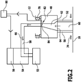
- the floor cleaning machine 10 comprises a suction device 46, via which liquid from the bottom 18 can be absorbed.
- the suction device 46 has a suction bar 48, on which (at least) a first suction lip 50 and a second suction lip 52 (FIG. Figures 2 . 3 (a), 3 (b), 3 (c) . 4 ) are arranged.
- the suction bar 48 is arranged behind the rear wheel 16 relative to a forward direction of travel.
- the second suction lip 52 is located closer to the rear wheel 16 than the first suction lip 50.
- About the suction bar 48 liquid is sucked and in a dirty water tank 53 (FIGS. FIG. 2 ).
- a suction bar 48 corresponding Saugbalken is arranged in front of the rear wheel 16.
- the suction bar can also be arranged directly on the floor cleaning device 38.
- the suction bar can also be integrated directly into the floor cleaning device.
- a suction bar is arranged in front of (between the floor cleaning device 38 and the front wheel 14) or behind (between the rear wheel device 16 and the floor cleaning device 38) of the floor cleaning device 38.
- the blower device 54 is driven by a motor 56, which is in particular an electric motor.
- the blower device 54 is fluidly connected to the suction bar 48 via a pipe device 58.
- the first squeegee 50 and the second squeegee 52 contact the floor 18. Between the first squeegee 50 and the second squeegee 52, a space 60 is formed. Laterally, the space 60 is closed, for example, by a corresponding shaping of the first suction lip 50 and / or the second suction lip 52, in which the suction lips 50, 52 touch.
- the space 60 is not completely closed, but partially closed.
- the suction bar 48 has one or more Absaugeausnaturalened 62.
- the Absaugeausnaturalung 62 or the Absaugeausappel 62 have an orifice 64 in the space 60.
- the Absaugeausnaturalung 62 or Absaugeausnaturalungen 62 are also connected to the tube device 58.
- the blower 54 generates a suction flow (in FIG. 2 indicated by the reference numeral 66).
- This suction 66 causes a Negative pressure in the space 60, to effect a suction, in particular of excess liquid.
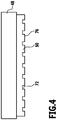
- the first suction lip 50 and / or the second suction lip 52 are each provided with recesses 72 through which ambient air (in FIG. 2 indicated by the arrow with reference numeral 74), in the space 60 can be flowed.
- the second suction lip 52 is provided with recesses 72.
- recesses 72 are arranged on the first suction lip 50 and the second suction lip 52 starting from a lower edge 76.
- the suction bar 48 is floatingly arranged on the chassis 12. It is held in particular on the chassis 12 via a spring device 78.
- the spring device 78 which in particular comprises one or more springs, serves, for example, to stabilize during cornering and to provide a restoring force from the bottom 18.
- the suction bar 48 is pressed by its own weight in the direction of the bottom 18.
- the first suction lip 50 and the second suction lip 52 are pressed onto the floor 18 and touch it.
- the resulting negative pressure additionally acts and the differential pressure loads the suction bar 48 in accordance with the adaptation of the suction lips 50 and 52 to the floor 18.
- the spring means 78 comprises compression springs which urge the suction bar against the floor to be cleaned.
- the floor cleaning machine 10 comprises a control and / or regulating device 80.
- the control and / or regulating device 80 is signal-effectively coupled to the fan device 54 with the motor 56.
- the control and / or regulating device 80 controls and / or regulates the power of the fan device 54 and thus the suction flow 66.
- the floor cleaning machine 10 includes a negative pressure detecting device 82.
- the negative pressure detecting device 82 detects a negative pressure in a Saugstrom arrangement at a suitable location.
- the negative pressure detection device 82 includes a pressure sensor 84 (or a plurality of pressure sensors 84). This pressure sensor 84 is arranged on the suction bar 48. It is arranged for example in the Absaugeausbloodung 62.
- the negative pressure determination device 82 (and in particular the pressure sensor 84) is signal-effectively coupled to the control and / or regulating device 80. She passes on her investigative signals to them.
- a suction operation of the floor cleaning machine 10 first presses the spring device 78 with a predetermined force the suction bar 48 in the direction of the bottom 18 and thus presses the first suction lip 50 and the second suction lip 52 against the bottom 18.
- the blower 54 generates the suction stream 66.
- the prevailing Vacuum on the suction bar 48 determines the relative position of the first suction lip 50 and the second suction lip 52 to the bottom 18.
- the prevailing negative pressure is in turn determined by the power setting of the blower 54 and by the inflow of ambient air 74 into the space 60. These inflow conditions are basically dependent on the type of floor 18. They may be different if the floor 18 is smooth or rough.
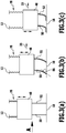
- An optimized suction result is obtained when an angle of incidence 86 (FIG. FIG. 3 (b) ) for the first suction lip 50 and the suction lip 52 is at a certain desired value or in a certain desired value range.
- an angle of incidence 86 (FIG. FIG. 3 (b) ) for the first suction lip 50 and the suction lip 52 is at a certain desired value or in a certain desired value range.
- the Incidence angle 86 is the angle which lies between the corresponding suction lip 50 or 52 and the bottom 18 at the point at which the suction lip touches the bottom 18.
- angle of attack 86 is about 45 ° and, for example, in a range between 35 ° and 55 °.
- FIG. 3 (a) an angle of incidence 86 of approximately 90 ° is shown.
- FIG. 3 (c) an angle of attack of approximately 0 ° is shown.
- the angle of attack 86 is predetermined by the power of the fan 54. However, with the same power setting, the angle of attack 86 may be different for the same suction bar 48 for different floors 18. In the FIG. 3 (b) shown relative position of the first suction lip 50 and the second suction lip 52 with an angle of attack 86 in the aforementioned setpoint range is optimal for the suction result.
- the negative pressure determined by the vacuum detecting means 82 is a measure of the relative position of the first suction lip 50 and the second suction lip 52 to the bottom 18, that is, the angle of attack 86.
- the negative pressure in particular in the Absaugeaus Principleung 62 is set to a desired value via appropriate power setting of the fan means 54 in order to obtain as independent of the nature of the bottom 18 an optimized angle of attack 86.
- the control and / or regulating device 80 receives via the negative pressure detection device 82 corresponding determination results and in particular measurement results of the one or more pressure sensors 84 for the present negative pressure. If there is a deviation from a desired value or a setpoint range for the negative pressure, then the power of the motor is correspondingly by controlling the motor 56 Blower 54 varies to bring the vacuum to a desired value and thereby set the optimized angle of attack 86.
- the setting is carried out in particular automatically, so that the floor cleaning machine 10 recognizes a kind of variation of the soil condition without intervention of a driver and independently performs an adjustment in the power setting of the blower 54 to obtain an optimized suction even in a soil condition variation.
- a control method is carried out, wherein a control objective is to set a vacuum setpoint value, in particular in the suction cutout 62, and thus to set a desired value for the setting angle 86.
- the variable size is the power of the blower device 54, to which the control and / or regulating device 80 correspondingly drives the motor 56.
- the regulation takes place in such a way (cf. FIG. 5 ) that a check 88 of the negative pressure (determined by the negative pressure detection device 82) takes place. If test 88 shows that the determined vacuum is below the setpoint (in FIG. 5 indicated by the reference numeral 90), then the power of the blower 54 is increased. This is in FIG. 5 indicated by the reference numeral 92.
- an optimized suction is achieved, which in FIG. 5 is indicated by the reference numeral 96.
- An optimized suction result means that the angle of attack 86 is at its desired value or in its desired value range.
- test 88 shows that the negative pressure in the Absaugeaus Principleung 82 is above the setpoint (in FIG. 5 indicated by the reference numeral 98), then the power of the blower 54 is reduced. This is in FIG. 5 indicated by the reference numeral 100.
- the desired value should then be reached and the step 94 carried out.
- the user intervention is in particular a check of the floor cleaning machine 10 or a cleaning of the floor cleaning machine 10 or an exchange of a suction lip.
- the test 88 takes place permanently and, for example, at predetermined time intervals.
- the floor cleaning machine 10 can perform an adaptation to varying ground conditions independently and automatically in order to obtain an optimized suction result even with different soil conditions.
- a regulation takes place in such a way that at least approximately the first suction lip 50 and the second suction lip 52 are at the optimized setting angle 86 or in an optimized setting angle range (nominal value or nominal value range) relative to the bottom 18, irrespective of the ground conditions.
- blower 54 Basically, lower performance of the blower 54 is required on smoother floors compared to rough floors.
- the power of the fan device 54 is automatically adjusted in the drive-suction mode of the floor cleaning machine 10 in order to obtain an optimized suction result.
- the negative pressure which prevails on the suction bar 48 is a measure of the angle of incidence 86 of the suction lips 50 and 52.
- the desired value of the negative pressure or the corresponding desired value range depends on the design of the suction bar 48 in combination with the design of the spring device 78.
- the corresponding desired value or setpoint range in the control and / or regulating device is stored in a table or as a function of the design of the suction bar 48 and the spring device 78.
- the negative pressure can in principle be determined by the negative pressure detection device 82 at other locations than at the suction bar 48. By determining the negative pressure data by the vacuum detection device 82 additional warning or evaluation options exist. For example, a warning message can be given to an operator if the vacuum required for cleaning purposes can not be established.
- a warning or information display for wear of the suction lips 50, 52 take place.
- a corresponding calculation rule is stored in the control and / or regulating device 80 for this purpose.
- the method according to the invention can also be used on other types of floor cleaning machines.
- it can be used on a vacuum robot or used on articulated floor cleaning machines. It is used in particular in self-propelled floor cleaning machines.
Landscapes
- Nozzles For Electric Vacuum Cleaners (AREA)
- Electric Vacuum Cleaner (AREA)
- Cleaning In General (AREA)
Applications Claiming Priority (1)
| Application Number | Priority Date | Filing Date | Title |
|---|---|---|---|
| PCT/EP2013/060962 WO2014191024A1 (de) | 2013-05-28 | 2013-05-28 | Verfahren zur einstellung einer position von sauglippen einer bodenreinigungsmaschine und bodenreinigungsmaschine |
Publications (2)
| Publication Number | Publication Date |
|---|---|
| EP3003113A1 EP3003113A1 (de) | 2016-04-13 |
| EP3003113B1 true EP3003113B1 (de) | 2017-10-18 |
Family
ID=48539138
Family Applications (1)
| Application Number | Title | Priority Date | Filing Date |
|---|---|---|---|
| EP13726173.1A Active EP3003113B1 (de) | 2013-05-28 | 2013-05-28 | Verfahren zur einstellung einer position von sauglippen einer bodenreinigungsmaschine und bodenreinigungsmaschine |
Country Status (5)
| Country | Link |
|---|---|
| US (1) | US10779697B2 (da) |
| EP (1) | EP3003113B1 (da) |
| CN (1) | CN105392408B (da) |
| DK (1) | DK3003113T3 (da) |
| WO (1) | WO2014191024A1 (da) |
Families Citing this family (12)
| Publication number | Priority date | Publication date | Assignee | Title |
|---|---|---|---|---|
| USD761505S1 (en) * | 2013-05-02 | 2016-07-12 | Techtronic Floor Care Technology Limited | Floor cleaning device |
| USD809721S1 (en) * | 2013-08-07 | 2018-02-06 | Kärcher North America, Inc. | Floor cleaning device |
| JP1599654S (da) * | 2015-06-26 | 2018-03-12 | ||
| USD825120S1 (en) * | 2016-03-23 | 2018-08-07 | Hawig Maschinenfabrik Gesellschaft Mit Beschraenkter Haftung | Floor cleaning machine |
| JP1626506S (da) * | 2016-06-10 | 2019-03-11 | ||
| USD856614S1 (en) * | 2017-07-19 | 2019-08-13 | Hawig Maschinenfabrik Gesellschaft Mit Beschraenkter Haftung | Floor cleaning machine |
| DE102017116747A1 (de) * | 2017-07-25 | 2019-01-31 | Vorwerk & Co. Interholding Gmbh | Bodenreinigungsgerät und Verfahren zu dessen Betrieb |
| USD904705S1 (en) * | 2018-05-01 | 2020-12-08 | David K. Thatcher | Mopping machine |
| USD965927S1 (en) | 2018-05-01 | 2022-10-04 | David K. Thatcher | Mopping machine |
| USD965928S1 (en) | 2018-05-01 | 2022-10-04 | David K. Thatcher | Mopping machine |
| WO2021089164A1 (de) | 2019-11-07 | 2021-05-14 | Alfred Kärcher SE & Co. KG | Bodenreinigungsmaschine und verfahren zum betreiben einer bodenreinigungsmaschine |
| EP4463043B1 (en) * | 2022-01-11 | 2025-05-14 | Versuni Holding B.V. | A cleaning element for attaching to a cleaner head and a cleaner head to which a cleaning element is attachable |
Family Cites Families (13)
| Publication number | Priority date | Publication date | Assignee | Title |
|---|---|---|---|---|
| US3649995A (en) * | 1970-02-16 | 1972-03-21 | Keltec Inc | Floor maintenance machine |
| US4483041A (en) * | 1982-09-30 | 1984-11-20 | Wetrok, Inc. | Support for a squeegee assembly |
| GB8421711D0 (en) | 1984-08-28 | 1984-10-03 | Unilever Plc | Floor-cleaning machine |
| DE4137886C2 (de) * | 1991-11-18 | 2000-06-08 | Miele & Cie | Verfahren zur Bürstenwalzensteuerung einer Staubsaugerbodendüse |
| ATA238091A (de) * | 1991-11-29 | 1994-05-15 | Abbrederis Heinrich | Vorrichtung zur behandlung, insbesondere reinigung, von ebenen flaechen |
| US5212848A (en) * | 1992-03-13 | 1993-05-25 | Tennant Company | Squeegee blade |
| US5319828A (en) * | 1992-11-04 | 1994-06-14 | Tennant Company | Low profile scrubber |
| FR2712167B1 (fr) | 1993-11-10 | 1995-12-22 | Seb Sa | Capteur de régulation de débit pour aspirateur. |
| US5987696A (en) * | 1996-12-24 | 1999-11-23 | Wang; Kevin W. | Carpet cleaning machine |
| CA2275899C (en) * | 1996-12-24 | 2005-01-25 | Kevin W. Wang | Carpet cleaning machine |
| US6073304A (en) * | 1997-10-22 | 2000-06-13 | Windsor Industries, Inc. | Squeegee adjustment method and apparatus |
| DE102007025388A1 (de) | 2007-05-30 | 2008-12-04 | Miele & Cie. Kg | Verfahren zum Betreiben eines Staubsaugers |
| DE102008010068B4 (de) | 2008-02-20 | 2013-02-28 | BSH Bosch und Siemens Hausgeräte GmbH | Vorrichtung zur automatischen Saugleistungsregelung eines Staubsaugers |
-
2013
- 2013-05-28 CN CN201380076952.5A patent/CN105392408B/zh active Active
- 2013-05-28 WO PCT/EP2013/060962 patent/WO2014191024A1/de not_active Ceased
- 2013-05-28 DK DK13726173.1T patent/DK3003113T3/da active
- 2013-05-28 EP EP13726173.1A patent/EP3003113B1/de active Active
-
2015
- 2015-11-20 US US14/947,504 patent/US10779697B2/en active Active
Non-Patent Citations (1)
| Title |
|---|
| None * |
Also Published As
| Publication number | Publication date |
|---|---|
| CN105392408B (zh) | 2018-04-24 |
| US20160073845A1 (en) | 2016-03-17 |
| EP3003113A1 (de) | 2016-04-13 |
| CN105392408A (zh) | 2016-03-09 |
| DK3003113T3 (da) | 2018-01-08 |
| US10779697B2 (en) | 2020-09-22 |
| WO2014191024A1 (de) | 2014-12-04 |
Similar Documents
| Publication | Publication Date | Title |
|---|---|---|
| EP3003113B1 (de) | Verfahren zur einstellung einer position von sauglippen einer bodenreinigungsmaschine und bodenreinigungsmaschine | |
| EP4186406B1 (de) | Bodenreinigungsmaschine mit stabeinrichtung | |
| DE602004002288T2 (de) | Fussbodenreinigungsmaschine | |
| EP3079554B1 (de) | Fahrbare bodenreinigungsmaschine | |
| WO2016058879A1 (de) | Flächen-reinigungsmaschine und verfahren zum betreiben einer flächen-reinigungsmaschine | |
| EP2717754B1 (de) | Selbstfahrende bodenreinigungsmaschine und verfahren zum betreiben einer selbstfahrenden bodenreinigungsmaschine | |
| DE102004014252A1 (de) | Verfahren zum Betreiben eines Staubsaugers mit einer Saugdüse sowie Staubsauger mit einer Saugdüse | |
| EP3952712A1 (de) | Flächen-reinigungsmaschine mit boost-modus und verfahren zum betreiben einer flächen-reinigungsmaschine | |
| DE102024109736A1 (de) | Flächenreinigungsgerät mit angetriebenem Seitenreinigungswerkzeug und Verfahren zum Betreiben eines Flächenreinigungsgeräts | |
| DE102024109746A1 (de) | Flächenreinigungsgerät mit Seitenreinigungswerkzeug und Verfahren zum Betreiben eines Flächenreinigungsgeräts | |
| EP4054393A1 (de) | Bodenreinigungsmaschine und verfahren zum betreiben einer bodenreinigungsmaschine | |
| DE102018113691A1 (de) | Bodenreinigungsmaschine mit Seitenschürzeneinrichtung und Verfahren zum Betreiben einer Bodenreinigungsmaschine | |
| EP2823746B1 (de) | Reinigungsvorrichtung zur Nassreinigung von Bodenflächen | |
| WO2023151833A1 (de) | Bodenreinigungsgerät mit kehreinrichtung und verfahren zum betreiben eines bodenreinigungsgeräts | |
| EP3313254A1 (de) | Reinigungsgerät mit einer um eine drehachse rotierbaren reinigungswalze | |
| EP4295739B1 (de) | Verfahren zum betrieb einer bodenreinigungsmaschine | |
| EP4514190A1 (de) | Bodenreinigungsgerät mit drucksensoreinrichtung | |
| WO2008006445A1 (de) | Reinigungsgerät für flächen | |
| EP1689277B1 (de) | Verfahren zum betreiben eines staubsaugers mit einer saugdüse sowie staubsauger mit einer saugduse | |
| EP3644817B1 (de) | Bodenreinigungsmaschine mit positioniereinrichtung für kehrwerkzeug | |
| DE212021000581U1 (de) | Bodenbehandlungsmaschine | |
| EP4195988B1 (de) | Bodenbearbeitungseinrichtung | |
| EP1924181B1 (de) | Rollensystem zum bewegen von gegenständen über verschmutzte böden | |
| DE202008011865U1 (de) | Staubsauger | |
| DE102017129800A1 (de) | Bodenplatte und Saugdüse mit einer Bodenplatte |
Legal Events
| Date | Code | Title | Description |
|---|---|---|---|
| PUAI | Public reference made under article 153(3) epc to a published international application that has entered the european phase |
Free format text: ORIGINAL CODE: 0009012 |
|
| 17P | Request for examination filed |
Effective date: 20151118 |
|
| AK | Designated contracting states |
Kind code of ref document: A1 Designated state(s): AL AT BE BG CH CY CZ DE DK EE ES FI FR GB GR HR HU IE IS IT LI LT LU LV MC MK MT NL NO PL PT RO RS SE SI SK SM TR |
|
| AX | Request for extension of the european patent |
Extension state: BA ME |
|
| DAX | Request for extension of the european patent (deleted) | ||
| GRAP | Despatch of communication of intention to grant a patent |
Free format text: ORIGINAL CODE: EPIDOSNIGR1 |
|
| INTG | Intention to grant announced |
Effective date: 20170512 |
|
| GRAS | Grant fee paid |
Free format text: ORIGINAL CODE: EPIDOSNIGR3 |
|
| GRAA | (expected) grant |
Free format text: ORIGINAL CODE: 0009210 |
|
| AK | Designated contracting states |
Kind code of ref document: B1 Designated state(s): AL AT BE BG CH CY CZ DE DK EE ES FI FR GB GR HR HU IE IS IT LI LT LU LV MC MK MT NL NO PL PT RO RS SE SI SK SM TR |
|
| REG | Reference to a national code |
Ref country code: GB Ref legal event code: FG4D Free format text: NOT ENGLISH |
|
| REG | Reference to a national code |
Ref country code: CH Ref legal event code: EP Ref country code: CH Ref legal event code: NV Representative=s name: ISLER AND PEDRAZZINI AG, CH |
|
| REG | Reference to a national code |
Ref country code: AT Ref legal event code: REF Ref document number: 937203 Country of ref document: AT Kind code of ref document: T Effective date: 20171115 Ref country code: IE Ref legal event code: FG4D Free format text: LANGUAGE OF EP DOCUMENT: GERMAN |
|
| REG | Reference to a national code |
Ref country code: DE Ref legal event code: R096 Ref document number: 502013008606 Country of ref document: DE |
|
| REG | Reference to a national code |
Ref country code: DK Ref legal event code: T3 Effective date: 20180103 |
|
| REG | Reference to a national code |
Ref country code: NL Ref legal event code: MP Effective date: 20171018 |
|
| REG | Reference to a national code |
Ref country code: LT Ref legal event code: MG4D |
|
| PG25 | Lapsed in a contracting state [announced via postgrant information from national office to epo] |
Ref country code: NL Free format text: LAPSE BECAUSE OF FAILURE TO SUBMIT A TRANSLATION OF THE DESCRIPTION OR TO PAY THE FEE WITHIN THE PRESCRIBED TIME-LIMIT Effective date: 20171018 |
|
| REG | Reference to a national code |
Ref country code: FR Ref legal event code: PLFP Year of fee payment: 6 |
|
| PG25 | Lapsed in a contracting state [announced via postgrant information from national office to epo] |
Ref country code: SE Free format text: LAPSE BECAUSE OF FAILURE TO SUBMIT A TRANSLATION OF THE DESCRIPTION OR TO PAY THE FEE WITHIN THE PRESCRIBED TIME-LIMIT Effective date: 20171018 Ref country code: NO Free format text: LAPSE BECAUSE OF FAILURE TO SUBMIT A TRANSLATION OF THE DESCRIPTION OR TO PAY THE FEE WITHIN THE PRESCRIBED TIME-LIMIT Effective date: 20180118 Ref country code: LT Free format text: LAPSE BECAUSE OF FAILURE TO SUBMIT A TRANSLATION OF THE DESCRIPTION OR TO PAY THE FEE WITHIN THE PRESCRIBED TIME-LIMIT Effective date: 20171018 Ref country code: FI Free format text: LAPSE BECAUSE OF FAILURE TO SUBMIT A TRANSLATION OF THE DESCRIPTION OR TO PAY THE FEE WITHIN THE PRESCRIBED TIME-LIMIT Effective date: 20171018 Ref country code: ES Free format text: LAPSE BECAUSE OF FAILURE TO SUBMIT A TRANSLATION OF THE DESCRIPTION OR TO PAY THE FEE WITHIN THE PRESCRIBED TIME-LIMIT Effective date: 20171018 |
|
| PG25 | Lapsed in a contracting state [announced via postgrant information from national office to epo] |
Ref country code: IS Free format text: LAPSE BECAUSE OF FAILURE TO SUBMIT A TRANSLATION OF THE DESCRIPTION OR TO PAY THE FEE WITHIN THE PRESCRIBED TIME-LIMIT Effective date: 20180218 Ref country code: LV Free format text: LAPSE BECAUSE OF FAILURE TO SUBMIT A TRANSLATION OF THE DESCRIPTION OR TO PAY THE FEE WITHIN THE PRESCRIBED TIME-LIMIT Effective date: 20171018 Ref country code: RS Free format text: LAPSE BECAUSE OF FAILURE TO SUBMIT A TRANSLATION OF THE DESCRIPTION OR TO PAY THE FEE WITHIN THE PRESCRIBED TIME-LIMIT Effective date: 20171018 Ref country code: PT Free format text: LAPSE BECAUSE OF FAILURE TO SUBMIT A TRANSLATION OF THE DESCRIPTION OR TO PAY THE FEE WITHIN THE PRESCRIBED TIME-LIMIT Effective date: 20180219 Ref country code: GR Free format text: LAPSE BECAUSE OF FAILURE TO SUBMIT A TRANSLATION OF THE DESCRIPTION OR TO PAY THE FEE WITHIN THE PRESCRIBED TIME-LIMIT Effective date: 20180119 Ref country code: HR Free format text: LAPSE BECAUSE OF FAILURE TO SUBMIT A TRANSLATION OF THE DESCRIPTION OR TO PAY THE FEE WITHIN THE PRESCRIBED TIME-LIMIT Effective date: 20171018 Ref country code: BG Free format text: LAPSE BECAUSE OF FAILURE TO SUBMIT A TRANSLATION OF THE DESCRIPTION OR TO PAY THE FEE WITHIN THE PRESCRIBED TIME-LIMIT Effective date: 20180118 |
|
| REG | Reference to a national code |
Ref country code: DE Ref legal event code: R097 Ref document number: 502013008606 Country of ref document: DE |
|
| REG | Reference to a national code |
Ref country code: DE Ref legal event code: R082 Ref document number: 502013008606 Country of ref document: DE Representative=s name: HOEGER, STELLRECHT & PARTNER PATENTANWAELTE MB, DE Ref country code: DE Ref legal event code: R081 Ref document number: 502013008606 Country of ref document: DE Owner name: ALFRED KAERCHER SE & CO. KG, DE Free format text: FORMER OWNER: ALFRED KAERCHER GMBH & CO. KG, 71364 WINNENDEN, DE |
|
| PG25 | Lapsed in a contracting state [announced via postgrant information from national office to epo] |
Ref country code: SK Free format text: LAPSE BECAUSE OF FAILURE TO SUBMIT A TRANSLATION OF THE DESCRIPTION OR TO PAY THE FEE WITHIN THE PRESCRIBED TIME-LIMIT Effective date: 20171018 Ref country code: EE Free format text: LAPSE BECAUSE OF FAILURE TO SUBMIT A TRANSLATION OF THE DESCRIPTION OR TO PAY THE FEE WITHIN THE PRESCRIBED TIME-LIMIT Effective date: 20171018 Ref country code: CZ Free format text: LAPSE BECAUSE OF FAILURE TO SUBMIT A TRANSLATION OF THE DESCRIPTION OR TO PAY THE FEE WITHIN THE PRESCRIBED TIME-LIMIT Effective date: 20171018 |
|
| RAP2 | Party data changed (patent owner data changed or rights of a patent transferred) |
Owner name: ALFRED KAERCHER SE & CO. KG |
|
| PLBE | No opposition filed within time limit |
Free format text: ORIGINAL CODE: 0009261 |
|
| STAA | Information on the status of an ep patent application or granted ep patent |
Free format text: STATUS: NO OPPOSITION FILED WITHIN TIME LIMIT |
|
| PG25 | Lapsed in a contracting state [announced via postgrant information from national office to epo] |
Ref country code: PL Free format text: LAPSE BECAUSE OF FAILURE TO SUBMIT A TRANSLATION OF THE DESCRIPTION OR TO PAY THE FEE WITHIN THE PRESCRIBED TIME-LIMIT Effective date: 20171018 Ref country code: SM Free format text: LAPSE BECAUSE OF FAILURE TO SUBMIT A TRANSLATION OF THE DESCRIPTION OR TO PAY THE FEE WITHIN THE PRESCRIBED TIME-LIMIT Effective date: 20171018 Ref country code: RO Free format text: LAPSE BECAUSE OF FAILURE TO SUBMIT A TRANSLATION OF THE DESCRIPTION OR TO PAY THE FEE WITHIN THE PRESCRIBED TIME-LIMIT Effective date: 20171018 |
|
| 26N | No opposition filed |
Effective date: 20180719 |
|
| PG25 | Lapsed in a contracting state [announced via postgrant information from national office to epo] |
Ref country code: MT Free format text: LAPSE BECAUSE OF FAILURE TO SUBMIT A TRANSLATION OF THE DESCRIPTION OR TO PAY THE FEE WITHIN THE PRESCRIBED TIME-LIMIT Effective date: 20171018 |
|
| PG25 | Lapsed in a contracting state [announced via postgrant information from national office to epo] |
Ref country code: SI Free format text: LAPSE BECAUSE OF FAILURE TO SUBMIT A TRANSLATION OF THE DESCRIPTION OR TO PAY THE FEE WITHIN THE PRESCRIBED TIME-LIMIT Effective date: 20171018 |
|
| REG | Reference to a national code |
Ref country code: BE Ref legal event code: MM Effective date: 20180531 |
|
| PG25 | Lapsed in a contracting state [announced via postgrant information from national office to epo] |
Ref country code: MC Free format text: LAPSE BECAUSE OF FAILURE TO SUBMIT A TRANSLATION OF THE DESCRIPTION OR TO PAY THE FEE WITHIN THE PRESCRIBED TIME-LIMIT Effective date: 20171018 |
|
| REG | Reference to a national code |
Ref country code: IE Ref legal event code: MM4A |
|
| PG25 | Lapsed in a contracting state [announced via postgrant information from national office to epo] |
Ref country code: LU Free format text: LAPSE BECAUSE OF NON-PAYMENT OF DUE FEES Effective date: 20180528 |
|
| PG25 | Lapsed in a contracting state [announced via postgrant information from national office to epo] |
Ref country code: IE Free format text: LAPSE BECAUSE OF NON-PAYMENT OF DUE FEES Effective date: 20180528 |
|
| PG25 | Lapsed in a contracting state [announced via postgrant information from national office to epo] |
Ref country code: BE Free format text: LAPSE BECAUSE OF NON-PAYMENT OF DUE FEES Effective date: 20180531 |
|
| REG | Reference to a national code |
Ref country code: AT Ref legal event code: MM01 Ref document number: 937203 Country of ref document: AT Kind code of ref document: T Effective date: 20180528 |
|
| PG25 | Lapsed in a contracting state [announced via postgrant information from national office to epo] |
Ref country code: AT Free format text: LAPSE BECAUSE OF NON-PAYMENT OF DUE FEES Effective date: 20180528 |
|
| PG25 | Lapsed in a contracting state [announced via postgrant information from national office to epo] |
Ref country code: TR Free format text: LAPSE BECAUSE OF FAILURE TO SUBMIT A TRANSLATION OF THE DESCRIPTION OR TO PAY THE FEE WITHIN THE PRESCRIBED TIME-LIMIT Effective date: 20171018 |
|
| PG25 | Lapsed in a contracting state [announced via postgrant information from national office to epo] |
Ref country code: HU Free format text: LAPSE BECAUSE OF FAILURE TO SUBMIT A TRANSLATION OF THE DESCRIPTION OR TO PAY THE FEE WITHIN THE PRESCRIBED TIME-LIMIT; INVALID AB INITIO Effective date: 20130528 Ref country code: MK Free format text: LAPSE BECAUSE OF NON-PAYMENT OF DUE FEES Effective date: 20171018 Ref country code: CY Free format text: LAPSE BECAUSE OF FAILURE TO SUBMIT A TRANSLATION OF THE DESCRIPTION OR TO PAY THE FEE WITHIN THE PRESCRIBED TIME-LIMIT Effective date: 20171018 |
|
| PG25 | Lapsed in a contracting state [announced via postgrant information from national office to epo] |
Ref country code: AL Free format text: LAPSE BECAUSE OF FAILURE TO SUBMIT A TRANSLATION OF THE DESCRIPTION OR TO PAY THE FEE WITHIN THE PRESCRIBED TIME-LIMIT Effective date: 20171018 |
|
| REG | Reference to a national code |
Ref country code: FR Ref legal event code: PLFP Year of fee payment: 11 |
|
| P01 | Opt-out of the competence of the unified patent court (upc) registered |
Effective date: 20230523 |
|
| PGFP | Annual fee paid to national office [announced via postgrant information from national office to epo] |
Ref country code: DE Payment date: 20250521 Year of fee payment: 13 |
|
| PGFP | Annual fee paid to national office [announced via postgrant information from national office to epo] |
Ref country code: GB Payment date: 20250401 Year of fee payment: 13 Ref country code: DK Payment date: 20250516 Year of fee payment: 13 |
|
| PGFP | Annual fee paid to national office [announced via postgrant information from national office to epo] |
Ref country code: IT Payment date: 20250422 Year of fee payment: 13 |
|
| PGFP | Annual fee paid to national office [announced via postgrant information from national office to epo] |
Ref country code: FR Payment date: 20250401 Year of fee payment: 13 |
|
| PGFP | Annual fee paid to national office [announced via postgrant information from national office to epo] |
Ref country code: CH Payment date: 20250601 Year of fee payment: 13 |