EP3000775A1 - Vorrichtung und verfahren zum befüllen von behältern mit einem füllprodukt - Google Patents
Vorrichtung und verfahren zum befüllen von behältern mit einem füllprodukt Download PDFInfo
- Publication number
- EP3000775A1 EP3000775A1 EP15187025.0A EP15187025A EP3000775A1 EP 3000775 A1 EP3000775 A1 EP 3000775A1 EP 15187025 A EP15187025 A EP 15187025A EP 3000775 A1 EP3000775 A1 EP 3000775A1
- Authority
- EP
- European Patent Office
- Prior art keywords
- filling
- product
- stirring element
- filling product
- stirring
- Prior art date
- Legal status (The legal status is an assumption and is not a legal conclusion. Google has not performed a legal analysis and makes no representation as to the accuracy of the status listed.)
- Granted
Links
Images

Classifications
-
- B—PERFORMING OPERATIONS; TRANSPORTING
- B01—PHYSICAL OR CHEMICAL PROCESSES OR APPARATUS IN GENERAL
- B01F—MIXING, e.g. DISSOLVING, EMULSIFYING OR DISPERSING
- B01F27/00—Mixers with rotary stirring devices in fixed receptacles; Kneaders
- B01F27/80—Mixers with rotary stirring devices in fixed receptacles; Kneaders with stirrers rotating about a substantially vertical axis
- B01F27/805—Mixers with rotary stirring devices in fixed receptacles; Kneaders with stirrers rotating about a substantially vertical axis wherein the stirrers or the receptacles are moved in order to bring them into operative position; Means for fixing the receptacle
- B01F27/806—Mixers with rotary stirring devices in fixed receptacles; Kneaders with stirrers rotating about a substantially vertical axis wherein the stirrers or the receptacles are moved in order to bring them into operative position; Means for fixing the receptacle with vertical displacement of the stirrer, e.g. in combination with means for pivoting the stirrer about a vertical axis in order to co-operate with different receptacles
-
- B—PERFORMING OPERATIONS; TRANSPORTING
- B67—OPENING, CLOSING OR CLEANING BOTTLES, JARS OR SIMILAR CONTAINERS; LIQUID HANDLING
- B67C—CLEANING, FILLING WITH LIQUIDS OR SEMILIQUIDS, OR EMPTYING, OF BOTTLES, JARS, CANS, CASKS, BARRELS, OR SIMILAR CONTAINERS, NOT OTHERWISE PROVIDED FOR; FUNNELS
- B67C3/00—Bottling liquids or semiliquids; Filling jars or cans with liquids or semiliquids using bottling or like apparatus; Filling casks or barrels with liquids or semiliquids
- B67C3/02—Bottling liquids or semiliquids; Filling jars or cans with liquids or semiliquids using bottling or like apparatus
- B67C3/22—Details
-
- B—PERFORMING OPERATIONS; TRANSPORTING
- B01—PHYSICAL OR CHEMICAL PROCESSES OR APPARATUS IN GENERAL
- B01F—MIXING, e.g. DISSOLVING, EMULSIFYING OR DISPERSING
- B01F27/00—Mixers with rotary stirring devices in fixed receptacles; Kneaders
- B01F27/05—Stirrers
- B01F27/11—Stirrers characterised by the configuration of the stirrers
- B01F27/112—Stirrers characterised by the configuration of the stirrers with arms, paddles, vanes or blades
- B01F27/1125—Stirrers characterised by the configuration of the stirrers with arms, paddles, vanes or blades with vanes or blades extending parallel or oblique to the stirrer axis
-
- B—PERFORMING OPERATIONS; TRANSPORTING
- B01—PHYSICAL OR CHEMICAL PROCESSES OR APPARATUS IN GENERAL
- B01F—MIXING, e.g. DISSOLVING, EMULSIFYING OR DISPERSING
- B01F27/00—Mixers with rotary stirring devices in fixed receptacles; Kneaders
- B01F27/23—Mixers with rotary stirring devices in fixed receptacles; Kneaders characterised by the orientation or disposition of the rotor axis
- B01F27/231—Mixers with rotary stirring devices in fixed receptacles; Kneaders characterised by the orientation or disposition of the rotor axis with a variable orientation during mixing operation, e.g. with tiltable rotor axis
- B01F27/2312—Mixers with rotary stirring devices in fixed receptacles; Kneaders characterised by the orientation or disposition of the rotor axis with a variable orientation during mixing operation, e.g. with tiltable rotor axis the position of the rotating shaft being adjustable in the interior of the receptacle, e.g. to locate the stirrer in different locations during the mixing
-
- B—PERFORMING OPERATIONS; TRANSPORTING
- B01—PHYSICAL OR CHEMICAL PROCESSES OR APPARATUS IN GENERAL
- B01F—MIXING, e.g. DISSOLVING, EMULSIFYING OR DISPERSING
- B01F35/00—Accessories for mixers; Auxiliary operations or auxiliary devices; Parts or details of general application
- B01F35/20—Measuring; Control or regulation
- B01F35/21—Measuring
- B01F35/211—Measuring of the operational parameters
- B01F35/2112—Level of material in a container or the position or shape of the upper surface of the material
-
- B—PERFORMING OPERATIONS; TRANSPORTING
- B01—PHYSICAL OR CHEMICAL PROCESSES OR APPARATUS IN GENERAL
- B01F—MIXING, e.g. DISSOLVING, EMULSIFYING OR DISPERSING
- B01F35/00—Accessories for mixers; Auxiliary operations or auxiliary devices; Parts or details of general application
- B01F35/20—Measuring; Control or regulation
- B01F35/21—Measuring
- B01F35/213—Measuring of the properties of the mixtures, e.g. temperature, density or colour
-
- B—PERFORMING OPERATIONS; TRANSPORTING
- B01—PHYSICAL OR CHEMICAL PROCESSES OR APPARATUS IN GENERAL
- B01F—MIXING, e.g. DISSOLVING, EMULSIFYING OR DISPERSING
- B01F35/00—Accessories for mixers; Auxiliary operations or auxiliary devices; Parts or details of general application
- B01F35/71—Feed mechanisms
- B01F35/717—Feed mechanisms characterised by the means for feeding the components to the mixer
- B01F35/7174—Feed mechanisms characterised by the means for feeding the components to the mixer using pistons, plungers or syringes
-
- B—PERFORMING OPERATIONS; TRANSPORTING
- B01—PHYSICAL OR CHEMICAL PROCESSES OR APPARATUS IN GENERAL
- B01F—MIXING, e.g. DISSOLVING, EMULSIFYING OR DISPERSING
- B01F35/00—Accessories for mixers; Auxiliary operations or auxiliary devices; Parts or details of general application
- B01F35/90—Heating or cooling systems
-
- B—PERFORMING OPERATIONS; TRANSPORTING
- B01—PHYSICAL OR CHEMICAL PROCESSES OR APPARATUS IN GENERAL
- B01F—MIXING, e.g. DISSOLVING, EMULSIFYING OR DISPERSING
- B01F35/00—Accessories for mixers; Auxiliary operations or auxiliary devices; Parts or details of general application
- B01F35/90—Heating or cooling systems
- B01F35/95—Heating or cooling systems using heated or cooled stirrers
-
- B—PERFORMING OPERATIONS; TRANSPORTING
- B01—PHYSICAL OR CHEMICAL PROCESSES OR APPARATUS IN GENERAL
- B01F—MIXING, e.g. DISSOLVING, EMULSIFYING OR DISPERSING
- B01F2101/00—Mixing characterised by the nature of the mixed materials or by the application field
- B01F2101/06—Mixing of food ingredients
-
- B—PERFORMING OPERATIONS; TRANSPORTING
- B01—PHYSICAL OR CHEMICAL PROCESSES OR APPARATUS IN GENERAL
- B01F—MIXING, e.g. DISSOLVING, EMULSIFYING OR DISPERSING
- B01F2101/00—Mixing characterised by the nature of the mixed materials or by the application field
- B01F2101/06—Mixing of food ingredients
- B01F2101/14—Mixing of ingredients for non-alcoholic beverages; Dissolving sugar in water
Definitions
- the present invention relates to a device for filling at least one container with a filling product, and to a method for filling a container with a filling product using such a device.
- filling devices for filling a filling product into containers in particular in the field of filling and metering machines for liquid or viscous foods such as drinks, it is known to provide the filling product in a product holding container, from which out the actual filling organs for filling the container with the filling product be fed.
- Product containment vessels are, for example, known in the form of a kettle, a ring bowl or a central boiler of a rotary filling machine and are usually provided in a plane above the filling members.
- the product holding container runs in normal operation in a rotary filler together with the filling members arranged thereon, in order to allow a correspondingly continuous filling of successively supplied containers to be filled.
- Piston fillers are usually used for high-viscosity filling products such as cream, ketchup or baby porridge.
- the different phases of the filling product in the filling and metering machine can separate, for example when the particles tend to sink or float.
- Such particle-containing filling products are filled, for example, as dairy products with fruit components or juices with pulp.
- motorized stirring device is integrated in the product holding container, permanently immersed in the product holding container used motorized stirring device. This can be achieved, for example, in the case of food filling by means of a piston dispenser in a rotary process, by motorized agitators or by rigid mixers, which immerse permanently into the filling product from a non-rotating part of the machine into the rotating, product-filled product holding container.
- Such a mixer thus ensures thorough mixing during the rotary movement of the product storage container and prevents the rapid separation of components of the product to be filled and thus a constant product quality.
- the DE 10 2012 104 275 A1 describes a device for filling containers with such a mixer, which is designed as a fixed and permanently immersed in the filling product agitator. Also from the DE 10 2010 031 873 A1 is such a fixed and permanently immersed in the filling product stirring blades.
- a disadvantage of this is that the risk of blister impact, foaming and / or mechanical stress on the filling product increases as a result of the permanent stirring of the filling product, which can lead to a deterioration in the filling accuracy and / or quality reduction of the filled filling product in the case of certain filling products.
- the product to be filled is tempered in many applications namely for microbiological reasons (for example in the hot filling of juices) or for reasons of processability in viscous or temperature-changing foods (for example, when filling fruit jellies or jams).
- the temperature control takes place via a heat exchanger provided in the product holding tank. Specifically, the temperature of the product takes place about a double-walled Fernvorhalte disposer, which is flowed through with cooling or heating media, or alternatively by fixed to the fixed part of the device heating coils, which immerse permanently in the filling product in Artsvorhalte disposer.
- two problem groups can be identified in apparatuses for filling containers with a rotatable product holding container: a) those which result from the permanent mixing of the filling product and b) those which are associated with the tempering of the filling product.
- An object of the present invention is to solve at least one of the above-mentioned problems.
- an object of the invention is to provide a device for filling at least one container with liquid filling product and a method for filling containers using such a device, which can achieve improved filling accuracy and avoid a conditional by the filling quality reduction of the filling product ,
- an apparatus for filling at least one container with a filling product comprising a product holding container for receiving the filling product and a stirring element for stirring the filling product received in the product holding container is proposed. According to the immersion depth of the stirring element in the product holding container is variable.
- the mechanical stress of the filling product can be varied and in particular in the regular Reduce filling operation, whereby on the one hand the impact of air in the filling product and on the other hand a deterioration of the quality of the filling product due to the mechanical stress caused by the stirring element can be avoided or at least reduced.
- the energy consumption resulting from the stirring of the filling product can be optimized.
- a “filling product” is understood to mean low-viscosity as well as highly viscous and pasty liquids, as well as multiphase liquids and those with particles. Beverages of all kinds are included as well as yogurt, jam, jelly and other foods that can be filled or dosed by means of a filling and metering machine, in particular a piston dispenser.
- the product holding container holds the filling product ready, from which then the filling members, for example the piston fillers, are fed for direct filling of the filling product into the containers.
- the product holding container is not completely filled with the filling product, but this is at a certain level of filling, one could say in a certain level, before.
- the filling level is determined by the water level when the product holding container is at rest.
- a stirring element is provided in the product holding container.
- several stirring elements may be provided. If in the following the term “the” or “one” stirring element is mentioned, not even several, then this happens only for the sake of illustration. This applies analogously to other features of the device, even if it is not explicitly stated that the feature in question can be implemented several times.
- the stirring element is at least movable between a stirring position, in which the stirring element is immersed in the filling product, and a rest position, in which the stirring element is located completely or partially outside the filling product.
- the mixing function provided by the stirring element is activated only when it is needed, for example when the regular filling operation is interrupted. The activation preferably takes place automatically.
- the stirring element can completely out of the Be brought out filling product. It may be that, due to the design, parts of the stirring element that do not or only slightly affect the filling product remain in the filling product. For this reason, even only partially moving the stirring member out of the filling product can achieve the above effects. However, in the rest position, the stirring element is preferably completely outside the filling product.
- the immersion depth of the stirring element in the endeavorvorhalte disposer is variable, then cases are included in which the stirring element is at certain positions, such as the rest position, outside the Artsvorhalte disposers.
- the stirring element is adjustable relative to the level of the filling product and can dip into the filling product.
- the stirring element is attached to a non-rotating device part and stationary relative to this in the direction of rotation of the product storage container.
- the device preferably has one or more device parts which do not rotate with respect to the product holding container, that is, are fixed in this sense.
- the stirring element is stationary, with the exception of the variability of the immersion depth or the position relative to Guehrix. For a particularly simple construction of the device is realized, since can be dispensed with elaborate mechanisms for driving and controlling the stirring element.
- the stirring element may, for example, have a guide blade, which causes the mixing of the filling product, and a guide blade carrier, which is connected directly to an adjusting mechanism.
- the adjusting mechanism may comprise a pneumatic cylinder and / or electric motor and / or electromagnet and so on.
- the stirring element is at least partially tempered. Due to the temperature control, in conjunction with the variability of the depth of immersion of the stirring a demand-based temperature control and at the same time a needs-based mixing of the filling product can be achieved. This is particularly important in interrupting the regular filling operation, during which both the mixing and the temperature of the filling product must be maintained in order to resume filling operation immediately be able to fill the present in the product holding container filling product and this particular does not have to be discarded.
- the mere variability of the immersion depth of the stirring element can contribute directly to demand-based temperature, because the start time and the end time of the temperature can be precisely determined by immersion and extraction of the stirring in or out of the product without an unwanted heat exchange due to the inertia of the heat exchanger or the materials of the stirring element takes place.
- stirring element is preferably fastened to the non-rotating part of the machine eliminates, for example, structurally complex rotary distributor constructions for circulating cooling or heating media or for circulating the product itself, slip rings for transmitting electrical energy to the rotating part of the machine, etc. Apparent effort and the control and regulation of the device are reduced to a minimum, thereby purchasing and maintenance costs can be saved.
- the temperature control can hold the filling product during the downtime in a specific temperature frame and a predetermined mixing state and the filling product must not be discarded. Also with regard to the temperature control over the stirring element, energy can be saved and the filling product can be conserved by the temperature control is carried out only when it is needed.
- the stirring element is electrically heated and / or flowed through with a heat / refrigerant.
- the vane may be embodied as an electrically heatable vane and the power may be supplied via a cable inside the vane carrier.
- several vanes may be provided. These can be coated with a product-compatible and / or heat-resistant material, for example Teflon or ceramic.
- a sheath made of stainless steel or other materials can be considered.
- the agitating element such as the one or more vanes, may be provided with one or more internally routed tubes, baffles, or hoses that carry a gaseous and / or liquid medium. in this connection Steam, hot water, cold water or other heat / refrigerant come into consideration. The tempering can of course also be done via evaporating media.
- the angle of incidence of the vane or the guide vanes is adjustable in order to achieve an optimal mixing success for the respective filling product or with respect to its viscosity.
- the dimension of the stirring elements, that is their extent, may optionally be provided changeable.
- a level sensor for measuring the filling product level or the filling level of the filling product is provided in the product holding container, whereby an efficient control of the stirring element, both in terms of its adjustability and its possible temperature control is simplified.
- the stirring element or its adjusting mechanism is connected to a controller, but also the level sensor for measuring the level of the filling product.
- a temperature sensor for measuring the temperature of the filling product is provided. This too can be connected to the above-mentioned control.
- the above stirring mechanism is particularly suitable for piston fillers, which realize a metering of the filling product via pistons.
- piston fillers are particularly preferably used for highly viscous liquids, such as yoghurt, jam, etc., which in many product variants are provided with additional solids such as, for example, pulp, chocolate pieces or caramel pieces.
- additional solids such as, for example, pulp, chocolate pieces or caramel pieces.
- unnecessary stirring and possibly unnecessary tempering of the quality of the filling product are detrimental.
- the particles are no longer finely ground by the constant mechanical action.
- An optimization of the stirring and temperature behavior in the regular filling operation and in an interruption of the regular filling operation is therefore particularly advantageous when using piston fillers.
- a method for filling at least one container with filling product by means of a device which has a product holding container for receiving the filling product and a stirring element for stirring the filling product accommodated in the product holding container, preferably one of the devices described above.
- the immersion depth of the stirring element in the product holding container is varied as a function of an operating state of the device.
- Possible operating states of the device include, inter alia, the regular filling operation and an interruption of the regular filling operation, for example in the event of a malfunction or maintenance of the system.
- other states can also determine the stirring and / or tempering mode of the stirring element.
- the stirring element when the regular filling operation of the device is interrupted, the stirring element is lowered into the filling product in the product holding container.
- the stirring element By further rotating the product holding container and / or actively operating the stirring element in rotation, the occurrence of a separation of the product components is reduced or avoided.
- the stirring element is arranged in the regular filling operation at least partially outside of the filling product and immersed in an interruption of the filling operation in the filling product.
- the stirring element Since, depending on the filling level of the filling product in the product holding container, the stirring element may not be covered, it is checked via the above-described level sensor, which preferably communicates with the control of the device, in a particular embodiment, whether sufficient filling product for covering the stirring element is included.
- filling product is supplied via a product feed valve until sufficient filling product is contained in the product holding container.
- a predetermined setpoint temperature can be set.
- the product holding tank continues to rotate, optionally at reduced speed, or the stirring element rotates to allow the filling product to flow past the stirring element, thereby heating or cooling the filling product, if necessary.
- the stirring element When restarting the device for resuming the regular filling operation, the stirring element is brought into the rest position, in which the stirring element is completely or partially moved out of the filling product.
- the present invention is particularly preferably used in the filling of containers with food, it is understood that the invention can also be implemented in other areas, for example in the filling or metering of paints, lacquers or other low-viscosity and high-viscosity liquids.
- other advantages and features of the present invention will become apparent from the following description of preferred embodiments.
- the features described therein may be implemented alone or in combination with one or more of the features mentioned above insofar as the features are not contradictory.
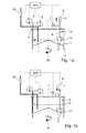
- FIGS. 1a and 1b schematically show a Rescuevorhalte variouser 1 a rotary filling machine, such as a piston filler, which is partially filled with a filling product 11.
- the filling level of the filling product 11 in the product holding tank 13 is referred to as the filling product level 12.
- Theloisvorhalte variouser 1 is rotatable about a rotation axis M around, as it is indicated by an arrow about the rotation axis M.
- Of the Product storage container 1 is closed in the embodiment shown with a cover 2, which is stationary and does not rotate with the Artsvorhalte disposer 1 accordingly.
- a stirring member 13 immersed, which serves to stir the filling product 11 accommodated in the product holding tank 1.
- the stirring element 13 can be varied with respect to its immersion depth into the product holding container 1, so that the immersion depth of the stirring element 13 can be varied correspondingly also with respect to the filling product level 12 of the filling product 11 in the product holding container 1.
- the immersion depth is preferably variable between an upper and a lower end position of the stirring element 13.
- the depth of immersion results from the retraction of the stirring element 13 into the product holding container 1 and can be objectively defined by the distance between the stirring element 13 and fixed parts of the product holding container 1 - for example, with respect to the bottom of the product holding container 1. Dipping the stirring element 13 deep into the product holding container 1 Thus, the distance of the stirring element 13 to the bottom of the endeavorvorhalte mattersers 1 is less than in a not so deep immersion of the stirring element 13.
- the immersion depth can also be defined relative to an upper edge of the Artsvorhalte mattersers 1.
- the immersion depth of the stirring element 13 in the Rescuevorhalte practicaler 1 can be achieved and the immersion depth can also be adjusted relative to Brown
- the immersion depth of the stirring element 13 is preferably infinitely variable or virtually infinitely variable between an upper and a lower end position.
- the stirring element 13 has, in the present embodiment, a guide blade carrier 4 and two guide vanes 5. Further, a drive in the form of a pneumatic cylinder 6 is provided, which is connected to the guide blade carrier 4 and makes it vertically adjustable together with the guide vanes 5, so that the immersion depth of the stirring element 13 can be varied accordingly in the Artsvorhalte interchangeer 1. Either the guide blade carrier 4 can be set only at the upper and lower end position, or the guide vane 4 can be set between the upper and lower end position in any position, so that a variable setting of the immersion depth can be achieved - depending on the respective Fill product level 12.
- the vanes 5 may further be rotated about the axis formed by the vane support 4 to stir the fill product 11.
- FIG. 1a shows a state in which the vanes 5 are outside of the filling product 11, so the stirring element 13 is not immersed in the filling product 11 and correspondingly can not interact with the filling product 11.
- the guide vanes 5 and a part of the vane support 4 are immersed in the filling product 11.
- the vane support 4 is provided in a lifting and lowering direction movable through the non-rotating cover 2 and optionally passed therethrough.
- the pneumatic cylinder 6 and / or the vane support 4 are fixed at a suitable position on a non-rotating device part of the rotary filler, so that the stirring element 13 is movable at least between an upper and a lower end position.
- the guide vanes 5 are designed to be coolable in order to cool the filling product 11.
- the number of temperature-controllable vanes 5 and / or their surface can be increased, reduced or otherwise geometrically adjusted in order to optimize a transfer of heat or cold to the filling product 11.
- FIGS. 2a to 2f Exemplary geometric embodiments of the vanes 5 are shown in FIGS FIGS. 2a to 2f shown.
- the angle of incidence of the guide vanes 5 may optionally be provided correspondingly adjustable depending on the application in order to realize an optimal mixing success and / or an optimal heat / cooling output.
- a level sensor 9 for measuring the Gres 12 of the filling product 11 is provided in the Domvorhalte varier 1.
- the level sensor 9 communicates with a controller, which may be designed as a programmable logic controller PLC.
- a temperature sensor 8 is provided, which also communicates with the controller PLC.
- the level sensor 9 and the temperature sensor 8 need not necessarily be provided directly in the product holding tank 1.
- the level sensor 9 and the temperature sensor 8 may also be omitted in certain embodiments or may be generally implemented as means for determining the corresponding parameters.
- the product level 12, for example, can also be determine from a detection of the inflow and outflow of filling product 11 in and out of the product holding container 1.
- a product supply valve 10 For filling the product holding container 1, a product supply valve 10 is provided.
- the pneumatic cylinder 6, the temperature controller 7, the temperature sensor 8, the level sensor 9 and the product supply valve 10 are connected to the programmable logic controller SPS.
- the programmable logic controller PLC records the sensor quantities as well as the control of the corresponding components.
- filling members 3 are shown schematically, which in the FIGS. 1a and 1b merely indicated as valves.
- FIGS. 1 a and 1 b illustrated device The following is a special way of operating in the FIGS. 1 a and 1 b illustrated device are set forth.
- the filling machine is driven empty when the container lock is activated and lowered via the adjusting device 6 of the guide blade carrier 4 in the filling product 11 in the Commandervorhalte constitutioner 1 (see FIG. 1 b) in that the electrically heatable vanes 5 are immersed in the filling product 11 in order to reduce a separation of product constituents with minimized blister impact and to maximize the heat transfer from the guide vanes 5 to the filling product.
- the vanes 5 may not be covered, via the level sensor 9 in the Fischvorhalte disposer 1 communicating with the controller PLC, checked whether sufficient filling product 11 is included to cover the vanes 5 and optionally is supplied via the product inlet valve 10 as long as filling product 11 until sufficient filling product 11 is contained in the product holding container 1.
- the adjusting device 6 can continue to be operated in order to allow the guide vanes 5 to continue to be immersed in the filling product 11.
- a predetermined setpoint temperature is set at the electrically heatable vanes 5 shown here.
- the product holding container 1 rotates at a reduced speed to allow the filling product 11 to flow past the heated guide vanes 5 while supplying heat energy and the filling product 11 for homogeneous temperature distribution and for reducing Separation to mix.
- the product holding container 1 can also come to a complete stop at a stop of the filling device and accordingly no longer rotate about the rotation axis M around.
- the movement of the filling product 11 is then applied via the rotation of the guide vanes 5 of the stirring element 13 in the filling product 11 in order to prevent segregation of different components.
- the stirring element 13 can then be returned to the upper end position and be pulled out of the filling product 11 in the product holding container 1.
- FIGS. 2a to 2f show embodiments of the stirring element 13.
- the stirring element 13 has a stirring rod 5, the inclination of which is optionally adjustable.
- the adjustability of the position of the stirring rod 5 is in the FIG. 2e shown by a heavily tilted alignment shown with dashed lines.
- Two cross stirrer bars are in the Figure 2c shown.
- Two mutually parallel, spaced stirring rods 5 are in the FIG. 2f shown.
- An embodiment with only one vane 5 is in the Figure 2d shown.
- the guide vanes or guide rods 5 may be suitably coated, for example with a product-compatible and / or heat-resistant material, such as Teflon or ceramic. Electric heating plates, which are coated with stainless steel sheet, are also conceivable as guide vanes, which have inside pipes, dividing plates and / or hoses for guiding a heat / refrigerant.
Landscapes
- Chemical & Material Sciences (AREA)
- Chemical Kinetics & Catalysis (AREA)
- Basic Packing Technique (AREA)
Abstract
Description
- Die vorliegende Erfindung betrifft eine Vorrichtung zum Befüllen mindestens eines Behälters mit einem Füllprodukt, sowie ein Verfahren zum Befüllen eines Behälters mit einem Füllprodukt unter Verwendung einer solchen Vorrichtung.
- In Füllvorrichtungen zum Abfüllen eines Füllprodukts in Behälter, insbesondere im Bereich der Abfüll- und Dosiermaschinen für flüssige oder viskose Lebensmittel wie beispielsweise Getränke, ist es bekannt, das Füllprodukt in einem Produktvorhaltebehälter bereitzustellen, aus welchem heraus die eigentlichen Füllorgane zum Befüllen der Behälter mit dem Füllprodukt gespeist werden. Produktvorhaltebehälter sind beispielsweise die Form eines Kessels, eines Ringkessels oder eines Zentralkessels einer Rundläuferfüllmaschine bekannt und sind gewöhnlich in einer Ebene oberhalb der Füllorgane vorgesehen. Der Produktvorhaltebehälter läuft im Normalbetrieb bei einem Rundläuferfüller zusammen mit den daran angeordneten Füllorganen um, um entsprechend eine kontinuierliche Befüllung von nacheinander zugeführten zu befüllenden Behältern zu ermöglichen.
- Als Füllorgane können entweder Kolbenfüllorgane vorgesehen sein, welche eine Behandlung des Füllprodukts unter Unterdruck und Überdruck ermöglichen, oder Füllorgane, aus welchen das Füllprodukt aufgrund seines Eigengewichts ausfließt. Kolbenfüller werden üblicherweise für hochviskose Füllprodukte wie beispielsweise Sahne, Ketchup oder Babybrei verwendet.
- Bei partikelhaltigen Füllprodukten können sich die unterschiedlichen Phasen des Füllprodukts in der Abfüll- und Dosiermaschine entmischen, etwa wenn die Partikel zum Absinken oder Aufschwimmen neigen. Solche partikelhaltigen Füllprodukte werden beispielsweise als Milchprodukte mit Fruchtbestandteilen oder Säfte mit Fruchtfleisch abgefüllt. Zur Vermeidung einer solchen Separation beziehungsweise Trennung von Produktbestandteilen wird eine im Produktvorhaltebehälter integrierte, permanent in den Produktvorhaltebehälter eintauchende motorische Rührvorrichtung eingesetzt. Dies kann, etwa bei der Lebensmittelabfüllung mittels eines Kolbendosierers im Rundlaufverfahren, durch motorische Rührwerke oder durch starre Mischer erreicht werden, die von einem nicht drehenden Teil der Maschine in den drehenden, mit Produkt gefüllten Produktvorhaltebehälter permanent ins Füllprodukt eintauchen. Ein solcher Mischer sorgt während der Drehbewegung des Produktvorhaltebehälters somit für eine Durchmischung und verhindert das schnelle Separieren von Bestandteilen des abzufüllenden Produkts und damit für eine gleichbleibende Produktqualität.
- Die
DE 10 2012 104 275 A1 beschreibt eine Vorrichtung zum Befüllen von Behältern mit einem solchen Mischer, der als feststehender und permanent in das Füllprodukt eintauchender Rührflügel ausgebildet ist. Auch aus derDE 10 2010 031 873 A1 geht ein solcher feststehender und permanent in das Füllprodukt eintauchender Rührflügel hervor. - Nachteilig an diesen ist, dass sich durch das permanente Durchrühren des Füllprodukts das Risiko des Blaseneinschlags, der Schaumbildung und/oder der mechanischen Belastung des Füllprodukts erhöht, was bei bestimmten Füllprodukten zur Verschlechterung der Füllgenauigkeit und/oder zur Qualitätsminderung des abgefüllten Füllprodukts führen kann.
- Neben den oben genannten Problemen, die aus der permanenten mechanischen Durchmischung des Füllprodukts resultieren, besteht ein weiteres Problem herkömmlicher Abfüll- und Dosiermaschinen darin, dass das Füllprodukt bei einer etwaigen Betriebsunterbrechung eine Temperaturänderung erfährt, wobei dieses dann möglicherweise nicht mehr im Bereich der zur Abfüllung erforderlichen Temperaturen vorliegt.
- Das abzufüllende Produkt wird in vielen Anwendungsfällen nämlich aus mikrobiologischen Gründen (etwa bei der Heißabfüllung von Säften) oder aus Gründen der Verarbeitbarkeit bei viskosen oder mit der Temperatur seine Textur verändernden Lebensmitteln (beispielsweise bei der Abfüllung von Fruchtgelees oder Konfitüren) temperiert.
- In der
DE 10 2012 104 275 A1 erfolgt die Temperierung über einen im Produktvorhaltebehälter vorgesehenen Wärmetauscher. Konkret erfolgt die Temperierung des Produkts etwa über einen doppelwandigen Produktvorhaltebehälter, der mit Kühl- oder Heizmedien durchströmt wird, oder alternativ durch am festen Teil der Vorrichtung befestigte Heizspiralen, die permanent in das Füllprodukt im Produktvorhaltebehälter eintauchen. - Bei der Temperierung des Dosierguts im rotierenden Produktvorhaltebehälter mittels Heiz- oder Kühlmantel ist eine konstruktiv aufwändige und kostenintensive Lösung mit Zu- und Abführung von Kälte-/Wärmemitteln (beispielsweise Heiß- oder Kaltwasser, Dampf) erforderlich, die einen verfahrenstechnischen und apparativen Mehraufwand nach sich zieht. Starre, permanent in den rotierenden Produktvorhaltebehälter eintauchende Temperierelemente (beispielsweise eine Heizwendel) sind auch aus reinigungstechnischer Sicht nicht optimal.
- Zusammenfassend lassen sich im Stand der Technik zwei Problemgruppen bei Vorrichtungen zum Befüllen von Behältern mit einem drehbaren Produktvorhaltebehälter identifizieren: a) solche, die sich aus der permanenten Durchmischung des Füllprodukts ergeben und b) solche, die mit der Temperierung des Füllprodukts zusammenhängen.
- Eine Aufgabe der vorliegenden Erfindung besteht darin, wenigstens eines der oben genannten Probleme zu lösen. Insbesondere liegt eine Aufgabe der Erfindung darin, eine Vorrichtung zum Befüllen mindestens eines Behälters mit flüssigem Füllprodukt sowie ein Verfahren zum Befüllen von Behältern unter Verwendung einer solchen Vorrichtung anzugeben, mit denen sich eine verbesserte Füllgenauigkeit erzielen sowie eine durch den Füllvorgang bedingte Qualitätsverminderung des Füllprodukts vermeiden lassen.
- Die Aufgabe wird mit einer Vorrichtung mit den Merkmalen des Anspruchs 1 gelöst. Vorteilhafte Weiterbildungen ergeben sich aus den Unteransprüchen, der folgenden allgemeinen Beschreibung sowie der Beschreibung bevorzugter Ausführungsformen.
- Entsprechend wird eine Vorrichtung zum Befüllen mindestens eines Behälters mit einem Füllprodukt, umfassend einen Produktvorhaltebehälter zur Aufnahme des Füllprodukts und ein Rührelement zum Rühren des im Produktvorhaltebehälter aufgenommenen Füllprodukts vorgeschlagen. Erfindungsgemäß ist die Eintauchtiefe des Rührelements in den Produktvorhaltebehälter variierbar.
- Durch die Variierbarkeit der Eintauchtiefe des Rührelements in den Produktvorhaltebehälter lässt sich die mechanische Beanspruchung des Füllprodukts variieren und insbesondere im regulären Füllbetrieb vermindern, wodurch zum einen der Lufteinschlag in das Füllprodukt und zum anderen eine Verschlechterung der Qualität des Füllprodukts aufgrund der mechanischen Beanspruchung durch das Rührelement vermieden oder zumindest vermindert werden kann. Außerdem lässt sich der Energieverbrauch, der aus dem Verrühren des Füllprodukts resultiert, optimieren.
- Unter einem "Füllprodukt" werden hier niedrig- als auch hochviskose und pastöse Flüssigkeiten verstanden, genauso wie mehrphasige Flüssigkeiten und solche mit Partikeln. Getränke aller Art sind ebenso einbezogen wie Joghurt, Konfitüre, Gelee und andere Lebensmittel, die sich mittels einer Abfüll- und Dosiermaschine, insbesondere einem Kolbendosierer, abfüllen beziehungsweise dosieren lassen. Der Produktvorhaltebehälter hält das Füllprodukt bereit, aus dem dann die Füllorgane, beispielsweise die Kolbenfüller, zum direkten Einfüllen des Füllprodukts in die Behälter gespeist werden.
- Üblicherweise ist der Produktvorhaltebehälter nicht vollständig mit dem Füllprodukt gefüllt, sondern dieses liegt bei einem gewissen Füllniveau, man könnte auch sagen in einer gewissen Füllhöhe, vor. Im Fall von Wasser wird das Füllniveau bei ruhendem Produktvorhaltebehälter etwa durch den Wasserspiegel bestimmt. In dem Produktvorhaltebehälter ist ein Rührelement vorgesehen. Selbstverständlich können auch mehrere Rührelemente vorgesehen sein. Wenn im Folgenden von "dem" oder "einem" Rührelement die Rede ist, nicht auch von mehreren, dann geschieht dies nur aus Gründen der Darstellung. Das gilt analog für andere Merkmale der Vorrichtung, auch wenn nicht explizit darauf hingewiesen wird, dass das betreffende Merkmal mehrfach realisiert sein kann.
- Vorzugsweise ist das Rührelement wenigstens zwischen einer Rührposition, in der das Rührelement in das Füllprodukt eingetaucht ist, und einer Ruheposition, in der sich das Rührelement vollständig oder teilweise außerhalb des Füllprodukts befindet, verfahrbar. Entsprechend wird die durch das Rührelement bereitgestellte Mischfunktion nur dann aktiviert, wenn sie benötigt wird, beispielsweise bei einer Unterbrechung des regulären Füllbetriebs. Die Aktivierung findet bevorzugt automatisch statt.
- Damit wird das Füllprodukt noch weiter geschont und es findet eine noch weitere Optimierung des Energieverbrauchs statt. Im Normalbetrieb der Vorrichtung, das heißt während des regulären Füllbetriebs, ist die Verweilzeit des Füllprodukts im Produktvorhaltebehälter relativ kurz und durch das stete Zuführen von Füllprodukt in den Produktvorhaltebehälter ist eine Durchmischung dann gegebenenfalls nicht notwendig. In diesem Fall kann das Rührelement vollständig aus dem Füllprodukt herausgefahren werden. Es mag sein, dass, konstruktionsbedingt, Teile des Rührelements, die das Füllprodukt nicht oder nur wenig beeinflussen, im Füllprodukt verbleiben. Aus diesem Grund kann auch ein nur teilweises Herausbewegen des Rührelements aus dem Füllprodukt die obigen Wirkungen erzielen. Vorzugsweise befindet sich das Rührelement in der Ruheposition allerdings vollständig außerhalb des Füllprodukts. In diesem Zusammenhang sei auf folgendes hingewiesen: wenn davon die Rede ist, dass die Eintauchtiefe des Rührelements im Produktvorhaltebehälter variierbar ist, dann sind Fälle mitumfasst, in denen sich das Rührelement an bestimmten Positionen, etwa der Ruheposition, außerhalb des Produktvorhaltebehälters befindet. Für die Funktion des Rührelements ist es bedeutend, dass das Rührelement relativ zum Niveau des Füllprodukts verstellbar ist und in das Füllprodukt eintauchen kann.
- Vorzugsweise ist das Rührelement an einem sich nicht drehenden Vorrichtungsteil angebracht und relativ zu diesem in Drehrichtung des Produktvorhaltebehälters stationär. Mit anderen Worten weist die Vorrichtung bevorzugt einen oder mehrere Vorrichtungsteile auf, die sich mit Bezug auf den Produktvorhaltebehälter nicht drehen, in diesem Sinne also fest sind. Relativ dazu ist gemäß dieser bevorzugten Ausführungsform das Rührelement stationär, mit Ausnahme der Variierbarkeit der Eintauchtiefe beziehungsweise der Position relativ zum Füllproduktniveau. Damit wird ein besonders einfacher Aufbau der Vorrichtung realisiert, da auf aufwändige Mechanismen zum Antreiben und Steuern des Rührelements verzichtet werden kann.
- Vorzugsweise erfolgt die Variation der Eintauchtiefe des Rührelements mittels eines Antriebs, bevorzugt mittels eines pneumatischen und/oder elektrischen Antriebs. Dadurch wird eine einfache und doch effiziente Möglichkeit der Verstellbarkeit realisiert. Das Rührelement kann hierbei beispielsweise eine Leitschaufel, welche die Durchmischung des Füllprodukts bewirkt, und einen Leitschaufelträger aufweisen, der direkt mit einem Verstellmechanismus verbunden ist. Der Verstellmechanismus kann einen Pneumatikzylinder und/oder Elektromotor und/oder Elektromagneten und so weiter aufweisen.
- Vorzugsweise ist das Rührelement wenigstens abschnittsweise temperierbar. Durch die Temperierbarkeit, in Zusammenwirkung mit der Variierbarkeit der Eintauchtiefe des Rührelements kann eine bedarfsgerechte Temperierung und gleichzeitig eine bedarfsgerechte Durchmischung des Füllprodukts erreicht werden. Dies ist insbesondere bei einer Unterbrechung des regulären Füllbetriebs von Bedeutung, während dessen sowohl die Durchmischung als auch die Temperatur des Füllprodukts aufrechterhalten werden muss, um bei einer Wiederaufnahme des Füllbetriebs sofort das sich im Produktvorhaltebehälter vorliegende Füllprodukt abfüllen zu können und dieses insbesondere nicht verworfen werden muss.
- Auch die bloße Variierbarkeit der Eintauchtiefe des Rührelements kann direkt zur bedarfsgerechten Temperierung beitragen, denn der Startzeitpunkt und der Endzeitpunkt der Temperierung können durch Eintauchen und Herausziehen des Rührelements in das beziehungsweise aus dem Füllprodukt präzise festgelegt werden, ohne dass ein ungewollter Wärmeaustausch aufgrund der Trägheit des Wärmetauschers beziehungsweise der Materialien des Rührelements erfolgt.
- Dadurch, dass das Rührelement bevorzugt am nicht rotierenden Teil der Maschine befestigt ist, entfallen beispielsweise konstruktiv aufwändige Drehverteilerkonstruktionen zur Zirkulation von Kühl- oder Heizmedien oder zur Zirkulation des Produkts selbst, Schleifringe zur Übertragung elektrischer Energie auf den rotierenden Teil der Maschine usw.. Der zusätzliche apparative Aufwand sowie die Ansteuerung und Regelung der Vorrichtung werden auf ein Minimum reduziert, wodurch Anschaffungs- und Wartungskosten eingespart werden können.
- Speziell im Falle der Dosierung von Lebensmitteln kann durch die Temperierung über das Rührelement während eines Anlagenstillstands Füllprodukt gespart werden, da die Temperierung das Füllprodukt während der Stillstandzeit in einem spezifischen Temperaturrahmen und einem vorgegebenen Durchmischungszustand halten kann und das Füllprodukt nicht verworfen werden muss. Auch im Hinblick auf die Temperierung über das Rührelement kann Energie eingespart werden und das Füllprodukt geschont werden, indem die Temperierung nur dann durchgeführt wird, wenn diese benötigt wird.
- Bevorzugt ist das Rührelement elektrisch beheizbar und/oder mit einem Wärme-/Kältemittel durchströmbar. Wenn das Rührelement, wie es oben angedeutet wurde, eine Leitschaufel und einen Leitschaufelträger aufweist, dann kann die Leitschaufel als elektrisch beheizbare Leitschaufel ausgeführt sein und die Stromzufuhr kann über ein Kabel im Inneren des Leitschaufelträgers erfolgen. Selbstverständlich können auch mehrere Leitschaufeln vorgesehen sein. Diese können mit einem produktverträglichen und/oder hitzeresistenten Material, beispielsweise Teflon oder Keramik, beschichtet sein. Auch eine Ummantelung aus Edelstahl oder anderen Materialien kann in Betracht gezogen werden. Alternativ kann das Rührelement, etwa die eine oder die mehreren Leitschaufeln, mit einem oder mehreren im Innern geführten Rohren, Trennblechen oder Schläuchen vorgesehen sein, welche ein gasförmiges und/oder flüssiges Medium führen. Hierbei kommen Dampf, Heißwasser, Kaltwasser oder andere Wärme-/Kältemittel in Betracht. Die Temperierung kann selbstverständlich auch über verdampfende Medien erfolgen.
- Vorzugsweise ist der Anstellwinkel der Leitschaufel oder der Leitschaufeln verstellbar, um einen optimalen Mischerfolg für das jeweilige Füllprodukt beziehungsweise bezüglich dessen Viskosität zu erzielen. Auch die Abmessung der Rührelemente, das heißt deren Ausdehnung, kann gegebenenfalls veränderbar vorgesehen sein.
- Vorzugsweise ist ein Niveausensor zur Messung des Füllproduktniveaus beziehungsweise der Füllhöhe des Füllprodukts im Produktvorhaltebehälter vorgesehen, wodurch eine effiziente Steuerung des Rührelements, sowohl hinsichtlich seiner Verstellbarkeit als auch seiner etwaigen Temperierbarkeit, vereinfacht wird. Dazu ist vorzugsweise nicht nur das Rührelement beziehungsweise dessen Verstellmechanismus mit einer Steuerung verbunden, sondern auch der Niveausensor zur Messung des Niveaus des Füllprodukts.
- Vorzugsweise ist zusätzlich dazu oder alternativ ein Temperatursensor zur Messung der Temperatur des Füllprodukts vorgesehen. Auch dieser kann mit der oben erwähnten Steuerung verbunden sein.
- Der obige Rührmechanismus ist insbesondere für Kolbenfüller geeignet, welche eine Dosierung des Füllprodukts über Kolben realisieren. Die Eignung ergibt sich daraus, dass Kolbenfüller besonders bevorzugt für hochviskose Flüssigkeiten, wie etwa Joghurt, Konfitüre usw., verwendet werden, welche in vielen Produktvarianten mit zusätzlichen Feststoffen wie beispielsweise Fruchtfleisch, Schokoladenstückchen oder Karamellstückchen versehen sind. In diesem Fall sind im regulären Füllbetrieb ein unnötiges Rühren und gegebenenfalls ein unnötiges Temperieren der Qualität des Füllprodukts abträglich. Insbesondere werden die Partikel nicht mehr durch die ständige mechanische Einwirkung kleingemahlen. Eine Optimierung des Rühr- und Temperaturverhaltens im regulären Füllbetrieb und bei einer Unterbrechung des regulären Füllbetriebs ist daher besonders bei der Verwendung von Kolbenfüllern vorteilhaft.
- Die oben gestellte Aufgabe wird weiterhin durch ein Verfahren mit den Merkmalen des Anspruchs 12 gelöst. Auch hier ergeben sich vorteilhafte Weiterbildungen aus den Unteransprüchen.
- Entsprechend wird ein Verfahren zum Befüllen mindestens eines Behälters mit Füllprodukt mittels einer Vorrichtung, die einen Produktvorhaltebehälter zur Aufnahme des Füllprodukts und ein Rührelement zum Rühren des im Produktvorhaltebehälter aufgenommenen Füllprodukts aufweist, vorgeschlagen, bevorzugt eine der oben beschriebenen Vorrichtungen. Erfindungsgemäß wird die Eintauchtiefe des Rührelements in den Produktvorhaltebehälter in Abhängigkeit von einem Betriebszustand der Vorrichtung variiert.
- Mögliche Betriebszustände der Vorrichtung umfassen unter anderem den regulären Füllbetrieb und eine Unterbrechung des regulären Füllbetriebs, etwa bei einer Störung oder Wartung der Anlage. Allerdings können auch andere Zustände den Rühr- und/oder Temperiermodus des Rührelements bestimmen.
- Gemäß einem bevorzugten Verfahren wird bei einer Unterbrechung des regulären Füllbetriebs der Vorrichtung das Rührelement in das Füllprodukt im Produktvorhaltebehälter abgesenkt. Indem sich der Produktvorhaltebehälter weiter dreht und/oder das Rührelement aktiv rotierend betrieben wird, wird das Auftreten einer Separation der Produktbestandteile reduziert oder vermieden. Gegebenenfalls findet auch ein Wärme-/Kälteübertrag vom Rührelement auf das Füllprodukt statt.
- Bevorzugt ist das Rührelement im regulären Füllbetrieb wenigstens teilweise außerhalb des Füllprodukts angeordnet und bei einer Unterbrechung des Füllbetriebs in das Füllprodukt eingetaucht.
- Da je nach Füllhöhe des Füllprodukts im Produktvorhaltebehälter das Rührelement möglicherweise nicht bedeckt ist, wird über den oben beschriebenen Niveausensor, der vorzugsweise mit der Steuerung der Vorrichtung kommuniziert, in einer besonderen Ausführungsform überprüft, ob ausreichend Füllprodukt zum Bedecken des Rührelements enthalten ist. Gegebenenfalls wird über ein Produktzulaufventil solange Füllprodukt zugeführt, bis ausreichend Füllprodukt im Produktvorhaltebehälter enthalten ist. Über den oben erwähnten Temperatursensor kann eine vorgegebene Solltemperatur eingestellt werden. Während des Stopps der Vorrichtung dreht sich der Produktvorhaltebehälter weiter, gegebenenfalls bei reduzierter Drehzahl, oder das Rührelement rotiert, um das Füllprodukt an dem Rührelement vorbeiströmen zu lassen und dabei das Füllprodukt, sofern erforderlich, zu erwärmen oder abzukühlen. Beim Wiederanfahren der Vorrichtung zur Wiederaufnahme des regulären Füllbetriebs wird das Rührelement in die Ruhelage gebracht, in der das Rührelement vollständig oder teilweise aus dem Füllprodukt herausbewegt ist. Wenngleich die vorliegende Erfindung besonders bevorzugt bei der Befüllung von Behältern mit Lebensmitteln zur Anwendung kommt, versteht es sich, dass die Erfindung auch in anderen Bereichen umgesetzt werden kann, beispielsweise bei der Abfüllung beziehungsweise Dosierung von Farben, Lacken oder anderen niedrig- und hochviskosen Flüssigkeiten. Darüber hinaus sind weitere Vorteile und Merkmale der vorliegenden Erfindung aus der folgenden Beschreibung bevorzugter Ausführungsformen ersichtlich. Die dort beschriebenen Merkmale können alleinstehend oder in Kombination mit einem oder mehreren der oben erwähnten Merkmale umgesetzt werden, insofern sich die Merkmale nicht widersprechen.
- Bevorzugte weitere Ausführungsformen und Aspekte der vorliegenden Erfindung werden durch die nachfolgende Beschreibung der Figuren näher erläutert. Dabei zeigen:
- Figuren 1a und 1b
- schematisch einen drehbaren Produktvorhaltebehälter für eine Vorrichtung zum Befüllen von Behältern, jeweils mit einem Rührelement, das sich in der
Figur 1 a außerhalb des Füllprodukts befindet und in derFigur 1b in das Füllprodukt eingetaucht ist, und - Figuren 2a bis 2f
- verschiedene Realisierungen des Rührelements.
- Im Folgenden werden bevorzugte Ausführungsbeispiele anhand der Figuren beschrieben. Dabei werden gleiche, ähnliche oder gleichwirkende Elemente in den unterschiedlichen Figuren mit identischen Bezugszeichen bezeichnet, und auf eine wiederholte Beschreibung dieser Elemente wird in der nachfolgenden Beschreibung teilweise verzichtet, um Redundanzen zu vermeiden.
- Die
Figuren 1a und 1 b zeigen schematisch einen Produktvorhaltebehälter 1 einer Rotationsfüllmaschine, beispielsweise eines Kolbenfüllers, der mit einem Füllprodukt 11 teilweise gefüllt ist. Die Füllhöhe des Füllprodukts 11 im Produktvorhaltebehälter 13 wird als das Füllproduktniveau 12 bezeichnet. Der Produktvorhaltebehälter 1 ist um eine Rotationsachse M herum drehbar, wie es mit einem Pfeil um die Rotationsachse M angedeutet ist. Der Produktvorhaltebehälter 1 ist in dem gezeigten Ausführungsbeispiel mit einem Deckel 2 geschlossen, der ortsfest ist und entsprechend nicht mit dem Produktvorhaltebehälter 1 umläuft. - In den Produktvorhaltebehälter 1 taucht ein Rührelement 13 ein, das zum Rühren des im Produktvorhaltebehälter 1 aufgenommenen Füllprodukts 11 dient. Das Rührelement 13 kann bezüglich seiner Eintauchtiefe in den Produktvorhaltebehälter 1 variiert werden, so dass die Eintauchtiefe des Rührelements 13 entsprechend auch bezüglich des Füllproduktniveaus 12 des Füllprodukts 11 im Produktvorhaltebehälter 1 variiert werden kann.
- Damit können unterschiedliche Eintauchtiefen des Rührelements 13 in das Füllprodukt 11 realisiert werden und das Rührelement 13 bei einer ersten Eintauchtiefe in den Produktvorhaltebehälter 1 vollständig oder teilweise mit dem Füllprodukt 11 in Kontakt stehen und bei einer zweiten Eintauchtiefe in den Produktvorhaltebehälter 1 vollständig außerhalb des Füllprodukts 11 angeordnet sein. Hierzu ist die Eintauchtiefe bevorzugt zwischen einer oberen und einer unteren Endposition des Rührelements 13 variierbar.
- Die Eintauchtiefe ergibt sich aus dem Einfahren des Rührelements 13 in den Produktvorhaltebehälter 1 und kann objektiv über den Abstand des Rührelements 13 gegenüber feststehenden Teilen des Produktvorhaltebehälters 1 definiert werden - beispielsweise gegenüber dem Boden des Produktvorhaltebehälters 1. Taucht das Rührelement 13 tief in den Produktvorhaltebehälter 1 ein, so ist der Abstand des Rührelements 13 zum Boden des Produktvorhaltebehälters 1 geringer, als bei einem nicht so tiefen Eintauchen des Rührelements 13. Die Eintauchtiefe kann auch gegenüber einem oberen Rand des Produktvorhaltebehälters 1 definiert werden.
- Entsprechend kann durch eine Variation der Eintauchtiefe des Rührelements 13 in den Produktvorhaltebehälter 1 auch eine Variation der Eintauchtiefe des Rührelements 13 in das jeweils im Produktvorhaltebehälter 1 aufgenommene Füllprodukt 11 erreicht werden und die Eintauchtiefe auch relativ zum Füllproduktniveau 12 eingestellt werden kann. Hierzu ist die Eintauchtiefe des Rührelements 13 bevorzugt stufenlos oder quasi stufenlos zwischen einer oberen und einer unteren Endposition variierbar.
- Dadurch, dass das Rührelement 13 in seiner oberen Endposition vollständig aus dem Füllprodukt 11 herausgehoben ist, kann ein durch das Rührelement 13 ungestörtes Abfüllen des Füllprodukts durchgeführt werden, wenn die Rotationsfüllmaschine mit der vorgesehenen Abfüllgeschwindigkeit betrieben wird und entsprechend der Produktvorhaltebehälter 1 mit der vorgesehenen Geschwindigkeit rotiert. Dabei wird durch die kontinuierliche Entnahme des Füllprodukts aus dem Produktvorhaltebehälter 1 in Kombination mit der Rotation des Produktvorhaltebehälters 1 eine Strömung des Füllprodukts 11 im Produktvorhaltebehälter 1 erreicht, die einer Entmischung der einzelnen Komponenten des Füllprodukts 11 entgegenwirkt. Weiterhin ist die Verweildauer des Füllprodukts 11 im Produktvorhaltebehälter 1 relativ gering, da über den Zulauf üblicherweise das gleiche Volumen an Füllprodukt 11 zufließt, wie es auch gleichzeitig über die Füllorgane in die zu befüllenden Behälter abfließt. Daher kann auf das Eintauchen des Rührelements 13 in das Füllprodukt 11 im regulären Füllbetrieb verzichtet werden, da eine Entmischung der Komponenten oder eine Veränderung anderer physikalischer Eigenschaften - beispielsweise eine Veränderung der Temperatur - nicht zu befürchten ist. Da das Rührelement 13 nicht in das Füllprodukt 11 eintaucht, wird der Abfüllvorgang nicht beeinflusst, da die Strömungsverhältnisse im Produktvorhaltebehälter 1 nicht durch das Rührelement 13 gestört werden.
- Das Rührelement 13 weist in der vorliegenden Ausführungsform einen Leitschaufelträger 4 und zwei Leitschaufeln 5 auf. Ferner ist ein Antrieb in Form eines Pneumatikzylinders 6 vorgesehen, der mit dem Leitschaufelträger 4 verbunden ist und diesen zusammen mit den Leitschaufeln 5 höhenverstellbar macht, so dass die Eintauchtiefe des Rührelements 13 in den Produktvorhaltebehälter 1 entsprechend variiert werden kann. Entweder kann der Leitschaufelträger 4 dabei nur an der oberen und der unteren Endposition festgelegt werden, oder der Leitschaufelträger 4 kann zwischen der oberen und unteren Endposition in beliebigen Positionen festgelegt werden, so dass ein variables Einstellen der Eintauchtiefe erreicht werden kann - auch abhängig von dem jeweiligen Füllproduktniveau 12.
- Die Leitschaufeln 5 können weiterhin um die durch den Leitschaufelträger 4 gebildete Achse herum in Rotation versetzt werden, um das Füllprodukt 11 zu rühren.
- Die
Figur 1a zeigt einen Zustand, in dem sich die Leitschaufeln 5 außerhalb des Füllprodukts 11 befinden, also das Rührelement 13 nicht in das Füllprodukt 11 eingetaucht ist und entsprechend auch nicht mit dem Füllprodukt 11 wechselwirken kann. In dem Zustand, der inFigur 1 b gezeigt ist, sind die Leitschaufeln 5 und ein Teil des Leitschaufelträgers 4 in das Füllprodukt 11 eingetaucht. Der Leitschaufelträger 4 ist in einer Hub- und Senkrichtung beweglich durch den nicht rotierenden Deckel 2 hindurch vorgesehen und gegebenenfalls durch diesen hindurch geführt. Der Pneumatikzylinder 6 und/oder der Leitschaufelträger 4 sind an einer geeigneten Stelle an einem nicht rotierenden Vorrichtungsteil des Rotationsfüllers befestigt, sodass das Rührelement 13 wenigstens zwischen einer oberen und einer unteren Endlage bewegbar ist. - Die Leitschaufeln 5 sind temperierbar, also beheizbar und/oder kühlbar. Im gezeigten Ausführungsbeispiel sind die Leitschaufeln 5 elektrisch beheizbar. Die Stromzufuhr zu den elektrisch beheizbaren Leitschaufeln 5 erfolgt über im Innern des Leitschaufelträgers 4 geführte Kabel und ist über eine Temperatursteuerung 7 regelbar ausgeführt. Entsprechend kann auf das Füllprodukt 11 Wärme übertragen werden.
- In einer weiteren Ausführung sind die Leitschaufeln 5 kühlbar ausgeführt, um das Füllprodukt 11 zu kühlen.
- Je nach Anforderung und Produkteigenschaften des Füllprodukts 11 kann die Anzahl der temperierbaren Leitschaufeln 5 und/oder deren Oberfläche vergrößert, verkleinert oder auf andere Weise geometrisch angepasst werden, um eine Übertragung von Wärme beziehungsweise Kälte auf das Füllprodukt 11 optimieren zu können.
- Beispielhafte geometrische Ausführungsformen der Leitschaufeln 5 sind in den
Figuren 2a bis 2f gezeigt. Der Anstellwinkel der Leitschaufeln 5 kann gegebenenfalls je nach Anwendungsfall entsprechend einstellbar vorgesehen sein, um einen optimalen Mischerfolg und/oder eine optimale Wärme-/Kälteabgabe zu realisieren. - In der dargestellten Ausführungsform ist ein Niveausensor 9 zur Messung des Füllproduktniveaus 12 des Füllprodukts 11 im Produktvorhaltebehälter 1 vorgesehen. Der Niveausensor 9 kommuniziert mit einer Steuerung, die etwa als Speicherprogrammierbare Steuerung SPS ausgelegt sein kann. Darüber hinaus ist ein Temperatursensor 8 vorgesehen, der ebenfalls mit der Steuerung SPS kommuniziert. Es sei darauf hingewiesen, dass der Niveausensor 9 und der Temperatursensor 8 nicht notwendigerweise direkt im Produktvorhaltebehälter 1 vorgesehen sein müssen. Ganz allgemein können der Niveausensor 9 und der Temperatursensor 8 in bestimmten Ausführungsformen auch weggelassen werden oder allgemein als Einrichtungen zur Ermittlung der entsprechenden Parameter ausgeführt sein. Das Produktniveau 12, beispielsweise, lässt sich auch aus einer Erfassung des Zu- und Ablaufs von Füllprodukt 11 in den und aus dem Produktvorhaltebehälter 1 bestimmen.
- Zum Füllen des Produktvorhaltebehälters 1 ist ein Produktzulaufventil 10 vorgesehen. Der Pneumatikzylinder 6, die Temperatursteuerung 7, der Temperatursensor 8, der Niveausensor 9 und das Produktzulaufventil 10 sind mit der Speicherprogrammierbaren Steuerung SPS verbunden. Über die Speicherprogrammierbare Steuerung SPS erfolgt die Erfassung der Sensorgrößen sowie die Ansteuerung der entsprechenden Komponenten.
- Im unteren Bereich des Produktvorhaltebehälters 1 sind schematisch Füllorgane 3 dargestellt, die in den
Figuren 1a und 1 b lediglich als Ventile angedeutet sind. - Im Folgenden soll eine spezielle Möglichkeit des Betriebs der in den
Figuren 1 a und 1 b dargestellten Vorrichtung dargelegt werden. Bei Anlagenstillstand wird die Abfüllmaschine bei aktivierter Behältersperre leer gefahren und über die Stellvorrichtung 6 der Leitschaufelträger 4 in das Füllprodukt 11 im Produktvorhaltebehälter 1 abgesenkt (sieheFigur 1 b) , wobei die elektrisch beheizbaren Leitschaufeln 5 ins Füllprodukt 11 eintauchen, um eine Separation von Produktbestandteilen bei minimiertem Blaseneinschlag zu reduzieren und den Wärmeübergang von den Leitschaufeln 5 auf das Füllprodukt zu maximieren. - Da je nach Füllproduktniveau 12 des Füllprodukts 11 im Produktvorhaltebehälter 1 die Leitschaufeln 5 möglicherweise nicht bedeckt sind, wird über den Niveausensor 9 im Produktvorhaltebehälter 1, der mit der Steuerung SPS kommuniziert, überprüft, ob ausreichend Füllprodukt 11 zum Bedecken der Leitschaufeln 5 enthalten ist und gegebenenfalls wird über das Produktzulaufventil 10 solange Füllprodukt 11 zugeführt, bis ausreichend Füllprodukt 11 im Produktvorhaltebehälter 1 enthalten ist. In einer Alternative oder zusätzlich kann auch die Stellvorrichtung 6 weiter betrieben werden, um die Leitschaufeln 5 weiter in das Füllprodukt 11 eintauchen zu lassen.
- Über die Temperatursteuerung 7, gegebenenfalls in Kommunikation mit der Steuerung SPS und dem damit verbundene Temperatursensor 8, wird an den hier gezeigten elektrisch beheizbaren Leitschaufeln 5 eine vorgegebene Solltemperatur eingestellt. Während eines Stopps der Abfüllvorrichtung dreht der Produktvorhaltebehälter 1 bei reduzierter Drehzahl, um das Füllprodukt 11 an den beheizten Leitschaufeln 5 vorbeiströmen zu lassen und dabei Wärmeenergie zuzuführen sowie das Füllprodukt 11 zur homogenen Temperaturverteilung und zur Reduzierung von Separation zu durchmischen. Der Produktvorhaltebehälter 1 kann bei einem Stopp der Abfüllvorrichtung auch zum vollständigen Stillstand kommen und entsprechend nicht mehr um die Rotationsachse M herum rotieren. Die Bewegung des Füllprodukts 11 wird dann über die Rotation der Leitschaufeln 5 des Rührelements 13 in dem Füllprodukt 11 aufgebracht, um ein Entmischen unterschiedlicher Komponenten zu verhindern.
- Beim Wiederanfahren der Anlage kann das Rührelement 13 dann wieder in die obere Endlage verbracht werden und aus dem Füllprodukt 11 im Produktvorhaltebehälter 1 herausgezogen werden.
- Die
Figuren 2a bis 2f zeigen Ausführungsbeispiele des Rührelements 13. In derFigur 2a sind zwei elektrisch beheizbare Leitschaufeln 5 vorgesehen, die an dem Leitschaufelträger 4 befestigt sind. In derFigur 2b weist das Rührelement 13 einen Rührstab 5 auf, dessen Neigung gegebenenfalls verstellbar ist. Die Verstellbarkeit der Lage des Rührstabs 5 ist in derFigur 2e dargestellt, indem eine stark gekippte Ausrichtung mit gestrichelten Linien gezeigt ist. Zwei über Kreuz vorgesehene Rührstäbe sind in derFigur 2c gezeigt. Zwei parallel zueinander ausgerichtete, beabstandete Rührstäbe 5 sind in derFigur 2f gezeigt. Ein Ausführungsbeispiel mit nur einer Leitschaufel 5 ist in derFigur 2d gezeigt. - Die Leitschaufeln beziehungsweise Leitstäbe 5 können geeignet beschichtet sein, beispielsweise mit einem produktverträglichen und/oder hitzeresistenten Material, etwa Teflon oder Keramik. Elektroheizplatten, die mit Edelstahlblech ummantelt sind, sind ebenso denkbar wie Leitschaufeln, die im Inneren Rohre, Trennbleche und/oder Schläuche zum Führen eines Wärme-/Kältemittels aufweisen.
- Soweit anwendbar, können alle einzelnen Merkmale, die in den Ausführungsbeispielen dargestellt sind, miteinander kombiniert und/oder ausgetauscht werden, ohne den Bereich der Erfindung zu verlassen.
-
- 1
- Produktvorhaltebehälter
- 2
- Deckel
- 3
- Füllorgan
- 4
- Leitschaufelträger
- 5
- Leitschaufel
- 6
- Pneumatikzylinder
- 7
- Temperatursteuerung
- 8
- Temperatursensor
- 9
- Niveausensor
- 10
- Produktzulaufventil
- 11
- Füllprodukt
- 12
- Füllhöhe des Füllprodukts
- 13
- Rührelement
- SPS
- Speicherprogrammierbare Steuerung
- M
- Rotationsachse des Produktvorhaltebehälters
Claims (14)
- Vorrichtung zum Befüllen mindestens eines Behälters mit Füllprodukt (11), umfassend einen Produktvorhaltebehälter (1) zur Aufnahme des Füllprodukts (11) und ein Rührelement (13) zum Rühren des im Produktvorhaltebehälter (1) aufgenommenen Füllprodukts (11),
dadurch gekennzeichnet, dass
die Eintauchtiefe des Rührelements (13) in den Produktvorhaltebehälter (1) variierbar ist. - Vorrichtung nach Anspruch 1, dadurch gekennzeichnet, dass das Rührelement (13) wenigstens zwischen einer Rührposition, in der das Rührelement (13) in das Füllprodukt (11) eingetaucht ist, und einer Ruheposition, in der sich das Rührelement (13) vollständig oder teilweise außerhalb des Füllprodukts (11) befindet, verfahrbar ist.
- Vorrichtung nach Anspruch 1 oder 2, dadurch gekennzeichnet, dass das Rührelement (13) an einem sich nicht drehenden Vorrichtungsteil angebracht und relativ zu diesem in Drehrichtung des Produktvorhaltebehälters (1) stationär ist.
- Vorrichtung nach einem der vorhergehenden Ansprüche, dadurch gekennzeichnet, dass die Variation der Eintauchtiefe des Rührelements (13) mittels eines Antriebs, bevorzugt eines pneumatischen und/oder elektrischen Antriebs, erfolgt.
- Vorrichtung nach einem der vorhergehenden Ansprüche, dadurch gekennzeichnet, dass das Rührelement (13) wenigstens abschnittsweise temperierbar ist.
- Vorrichtung nach Anspruch 5, dadurch gekennzeichnet, dass das Rührelement (13) wenigstens abschnittsweise elektrisch beheizbar und/oder kühlbar ist und/oder mit einem Wärme-/Kältemittel durchströmbar ist.
- Vorrichtung nach einem der vorstehenden Ansprüche, dadurch gekennzeichnet, dass das Rührelement (13) wenigstens eine Leitschaufel (5) aufweist.
- Vorrichtung nach Anspruch 7, dadurch gekennzeichnet, dass der Anstellwinkel der Leitschaufels (5) verstellbar ist.
- Vorrichtung nach einem der vorhergehenden Ansprüche, dadurch gekennzeichnet, dass ein Niveausensor (9) zur Messung des Füllproduktniveaus (12) im Produktvorhaltebehälter (1) vorgesehen ist.
- Vorrichtung nach einem der vorhergehenden Ansprüche, dadurch gekennzeichnet, dass ein Temperatursensor (8) zur Messung der Temperatur des Füllprodukts (11) im Produktvorhaltebehälter (1) vorgesehen ist.
- Vorrichtung nach einem der vorhergehenden Ansprüche, dadurch gekennzeichnet, dass mindestens ein Füllorgan in Form eines Kolbenfüllers zum Befüllen des mindestens einen Behälters mit dem Produktvorhaltebehälter (1) verbunden ist und bevorzugt gemeinsam mit diesem um dessen Rotationsachse (M) herum umläuft.
- Verfahren zum Befüllen mindestens eines Behälters mit einem Füllprodukt (11) mittels einer Vorrichtung, die einen Produktvorhaltebehälter (1) zur Aufnahme des Füllprodukts (11) und ein Rührelement (13) zum Rühren des im Produktvorhaltebehälter (1) aufgenommenen Füllprodukts (11) umfasst, bevorzugt gemäß einem der vorstehenden Ansprüche,
dadurch gekennzeichnet, dass
die Eintauchtiefe des Rührelements (13) in den Produktvorhaltebehälter (1) in Abhängigkeit von einem Betriebszustand der Vorrichtung variiert wird. - Verfahren nach Anspruch 12, dadurch gekennzeichnet, dass die Eintauchtiefe zwischen einer Rührposition, in der das Rührelement (13) in das Füllprodukt (11) eingetaucht ist, und einer Ruheposition, in der sich das Rührelement (13) vollständig oder teilweise außerhalb des Füllprodukts (11) befindet, variiert wird, bevorzugt automatisch.
- Verfahren nach Anspruch 12 oder 13, dadurch gekennzeichnet, dass das Rührelement (13) im regulären Füllbetrieb wenigstens teilweise außerhalb des Füllprodukts (11) angeordnet ist und bei einer Unterbrechung des Füllbetriebs in das Füllprodukt (11) eingetaucht ist.
Applications Claiming Priority (1)
| Application Number | Priority Date | Filing Date | Title |
|---|---|---|---|
| DE102014113986.0A DE102014113986A1 (de) | 2014-09-26 | 2014-09-26 | Vorrichtung und Verfahren zum Befüllen von Behältern mit einem Füllprodukt |
Publications (2)
| Publication Number | Publication Date |
|---|---|
| EP3000775A1 true EP3000775A1 (de) | 2016-03-30 |
| EP3000775B1 EP3000775B1 (de) | 2018-01-31 |
Family
ID=54238286
Family Applications (1)
| Application Number | Title | Priority Date | Filing Date |
|---|---|---|---|
| EP15187025.0A Active EP3000775B1 (de) | 2014-09-26 | 2015-09-28 | Vorrichtung und verfahren zum befüllen von behältern mit einem füllprodukt |
Country Status (4)
| Country | Link |
|---|---|
| US (1) | US10112158B2 (de) |
| EP (1) | EP3000775B1 (de) |
| CN (1) | CN105460867B (de) |
| DE (1) | DE102014113986A1 (de) |
Cited By (1)
| Publication number | Priority date | Publication date | Assignee | Title |
|---|---|---|---|---|
| WO2018085283A1 (en) * | 2016-11-01 | 2018-05-11 | Life Technologies Corporation | Liquid mixing system with vertically adjustable mixing element and method of use |
Families Citing this family (4)
| Publication number | Priority date | Publication date | Assignee | Title |
|---|---|---|---|---|
| US11439965B2 (en) * | 2018-03-22 | 2022-09-13 | Basf Coatings Gmbh | Method for producing coating medium compositions by means of gravimetric metering with mixing and adaptation of the height of the stirring element to the level |
| CN112844201A (zh) * | 2020-12-24 | 2021-05-28 | 湖北极森奥源生物科技有限公司 | 一种基于互联网的乳化锅控制系统 |
| US12180059B2 (en) | 2021-08-06 | 2024-12-31 | Swimc Llc | Automated container fill line with expert system |
| CN114984792B (zh) * | 2022-05-10 | 2023-09-19 | 宜兴市星光宝亿化工有限公司 | 一种水煤浆添加剂用搅拌装置及其使用方法 |
Citations (8)
| Publication number | Priority date | Publication date | Assignee | Title |
|---|---|---|---|---|
| DE563690C (de) * | 1930-10-19 | 1932-11-10 | I G Farbenindustrie Akt Ges | Ruehrwerksbehaelter mit elektrisch beheiztem Ruehrwerk |
| GB472673A (en) * | 1936-10-15 | 1937-09-28 | Stanley Frederick Broadhurst | Machines for filling containers with liquids or with materials in a liquid state |
| AU3974768A (en) * | 1968-06-26 | 1968-08-01 | Sulzer Brothers Limited | Apparatus for filling individual containers with sterile liquids |
| US4593612A (en) * | 1982-01-30 | 1986-06-10 | Herbert Rieger | Upright red wine fermentation tank |
| EP2055372A1 (de) * | 2007-11-01 | 2009-05-06 | Mettler-Toledo AG | Rührereinheit aufweisend einen Adapter |
| DE102010031873A1 (de) | 2010-07-21 | 2012-01-26 | Krones Aktiengesellschaft | Vorrichtung und Verfahren zum Befüllen von Behältnissen mit Reinigungseinrichtung |
| DE102012104275A1 (de) | 2012-05-16 | 2013-11-21 | Krones Ag | Vorrichtung und Verfahren zum Befüllen von Behältern mit flüssigem Füllgut |
| EP2689830A1 (de) * | 2012-07-26 | 2014-01-29 | Michael Niederbacher | Biogasanlage |
Family Cites Families (16)
| Publication number | Priority date | Publication date | Assignee | Title |
|---|---|---|---|---|
| US2691282A (en) * | 1949-06-21 | 1954-10-12 | Lyell Jennings | Cooling and storage apparatus for liquids |
| US2703966A (en) * | 1950-12-30 | 1955-03-15 | Lyell Jennings | Cooling and storage apparatus for liquids |
| DE1216845B (de) * | 1958-07-23 | 1966-05-18 | Lederle Pumpen & Maschf | Vorrichtung zum Ruehren, Mischen, Dispergieren u. dgl. von Fluessigkeiten |
| DE1954947U (de) * | 1966-12-07 | 1967-02-09 | Linde Ag | Tauchkuehler zum kuehlen von milch. |
| GB1474524A (de) * | 1973-07-06 | 1977-05-25 | ||
| FR2633036B1 (fr) * | 1988-06-21 | 1990-11-16 | Inst Kriobiologii | Appareil pour le refroidissement et la congelation d'objets biologiques |
| FR2642276B1 (fr) * | 1989-01-11 | 1991-05-17 | Thomas Fils Sa Ets | Dispositif pour le traitement du miel |
| AT395544B (de) * | 1990-11-23 | 1993-01-25 | Kreuziger Wolf Dieter Mag Ing | Vorrichtung fuer das mischen, homogenisieren oder umsetzen von wenigstens zwei komponenten |
| US5538462A (en) * | 1994-03-15 | 1996-07-23 | The Gleason Works | Lapping compound supply system for a gear finishing machine |
| JPH10277378A (ja) * | 1997-04-07 | 1998-10-20 | Ishikawajima Harima Heavy Ind Co Ltd | 発熱反応装置の攪拌装置 |
| US6491423B1 (en) * | 1998-03-11 | 2002-12-10 | Mc21, Incorporated | Apparatus for mixing particles into a liquid medium |
| US6825289B2 (en) * | 2001-04-02 | 2004-11-30 | Nippon Shokubai Co., Ltd. | Method for producing chemical reactive substance and polycarboxylic acid produced thereby |
| DE202005004188U1 (de) * | 2005-03-14 | 2005-05-19 | Harro Höfliger Verpackungsmaschinen GmbH | Vorrichtung zum Abfüllen von jeweils vorbestimmt großen Mengen an pulvrigem Füllgut |
| DE102006002545A1 (de) * | 2006-01-18 | 2007-07-19 | Ewald Dörken Ag | Siliziumbasiertes Korrosionsschutzmittel |
| CN101016143A (zh) * | 2007-02-14 | 2007-08-15 | 中国人民解放军第一一八医院 | 全自动药液加热搅拌配制过滤灌装机 |
| CN201676652U (zh) * | 2010-04-29 | 2010-12-22 | 周铭 | 一种灌装机上用的搅拌器 |
-
2014
- 2014-09-26 DE DE102014113986.0A patent/DE102014113986A1/de not_active Withdrawn
-
2015
- 2015-09-24 CN CN201510617372.3A patent/CN105460867B/zh active Active
- 2015-09-25 US US14/866,603 patent/US10112158B2/en active Active
- 2015-09-28 EP EP15187025.0A patent/EP3000775B1/de active Active
Patent Citations (8)
| Publication number | Priority date | Publication date | Assignee | Title |
|---|---|---|---|---|
| DE563690C (de) * | 1930-10-19 | 1932-11-10 | I G Farbenindustrie Akt Ges | Ruehrwerksbehaelter mit elektrisch beheiztem Ruehrwerk |
| GB472673A (en) * | 1936-10-15 | 1937-09-28 | Stanley Frederick Broadhurst | Machines for filling containers with liquids or with materials in a liquid state |
| AU3974768A (en) * | 1968-06-26 | 1968-08-01 | Sulzer Brothers Limited | Apparatus for filling individual containers with sterile liquids |
| US4593612A (en) * | 1982-01-30 | 1986-06-10 | Herbert Rieger | Upright red wine fermentation tank |
| EP2055372A1 (de) * | 2007-11-01 | 2009-05-06 | Mettler-Toledo AG | Rührereinheit aufweisend einen Adapter |
| DE102010031873A1 (de) | 2010-07-21 | 2012-01-26 | Krones Aktiengesellschaft | Vorrichtung und Verfahren zum Befüllen von Behältnissen mit Reinigungseinrichtung |
| DE102012104275A1 (de) | 2012-05-16 | 2013-11-21 | Krones Ag | Vorrichtung und Verfahren zum Befüllen von Behältern mit flüssigem Füllgut |
| EP2689830A1 (de) * | 2012-07-26 | 2014-01-29 | Michael Niederbacher | Biogasanlage |
Cited By (5)
| Publication number | Priority date | Publication date | Assignee | Title |
|---|---|---|---|---|
| WO2018085283A1 (en) * | 2016-11-01 | 2018-05-11 | Life Technologies Corporation | Liquid mixing system with vertically adjustable mixing element and method of use |
| US10898870B2 (en) | 2016-11-01 | 2021-01-26 | Life Technologies Corporation | Liquid mixing system with vertically adjustable mixing element and method of use |
| EP4137227A1 (de) * | 2016-11-01 | 2023-02-22 | Life Technologies Corporation | Flüssigkeitsmischsystem mit vertikal verstellbarem mischelement und verfahren zur verwendung |
| US11745151B2 (en) | 2016-11-01 | 2023-09-05 | Life Technologies Corporation | Liquid mixing system with vertically adjustable mixing element and method of use |
| US12214324B2 (en) | 2016-11-01 | 2025-02-04 | Life Technologies Corporation | Liquid mixing system with vertically adjustable mixing element and method of use |
Also Published As
| Publication number | Publication date |
|---|---|
| DE102014113986A1 (de) | 2016-03-31 |
| US10112158B2 (en) | 2018-10-30 |
| CN105460867A (zh) | 2016-04-06 |
| US20160089643A1 (en) | 2016-03-31 |
| EP3000775B1 (de) | 2018-01-31 |
| CN105460867B (zh) | 2018-02-06 |
Similar Documents
| Publication | Publication Date | Title |
|---|---|---|
| EP3000775B1 (de) | Vorrichtung und verfahren zum befüllen von behältern mit einem füllprodukt | |
| EP2255869B1 (de) | Horizontalmischer | |
| DE3901894C5 (de) | Vorrichtung zum Rühren eines strömungsfähigen Mediums | |
| DE69506094T2 (de) | Verfahren und Vorrichtung zum Rühren von Behandlungsflüssigkeit | |
| DE3414747C2 (de) | Abfüllverfahren und -vorrichtung | |
| US5911811A (en) | Apparatus for mixing and refining a chocolate mass | |
| US6129008A (en) | Apparatus for mixing and refining a chocolate mass | |
| EP0518025A2 (de) | Conche und Verfahren zum Betrieb einer solchen | |
| EP2625259B1 (de) | Verfahren und vorrichtung insbesondere zum maischen bei der herstellung von bier | |
| DE10110910C1 (de) | Mischer zum Herstellen pastöser Produkte wie Salben, Cremes und Emulsionen | |
| CH683322A5 (de) | Einrichtung und Verfahren zum Emulgieren eines Gutes. | |
| DE10202084A1 (de) | Misch- und Homogenisiermaschine | |
| DE102014001574B4 (de) | Verfahren und Vorrichtung zur kontinuierlichen Dosierung von wenigstens einer festkörperartigen, kleinstückigen Beimengung in eine Trägerflüssigkeit | |
| DE630904C (de) | Verfahren und Vorrichtung zum Behandeln von Fluessigkeiten in der Waerme bzw. kaelte | |
| EP1349686A1 (de) | Verfahren zum bereitstellen einer teilerstarrten legierungssuspension und vorrichtungen | |
| DE102006054215B4 (de) | Verfahren und Vorrichtung zum Temperieren von flüssigem Nahrungsmittel für Tiere | |
| DE2360278A1 (de) | Geraet zur behandlung von nahrungsmitteln, insbesondere milchprodukten | |
| DE1567297B2 (de) | Vorrichtung zum Temperieren einer Zuckerfüllmasse | |
| DE69926069T2 (de) | Horizontalgiessanlage | |
| DE1792510A1 (de) | Verfahren zur kontinuierlichen Sterilisation von pasteusen Lebensmitteln wie Fleischbraet,Babynahrung,Schmelzkaese od.dgl. | |
| AT317385B (de) | Misch- und/oder Knetmaschine | |
| DE19916053B4 (de) | Vorrichtung zum Homogenisieren fließfähiger Stoffe | |
| AT109851B (de) | Vorrichtung zum Kühlen von Fettemulsionen. | |
| DE1501195C (de) | Verfahren und Vorrichtung zur Her stellung von Brei halbgefrorener Kon sistenz | |
| DE3241209A1 (de) | Zucker-kochapparat und -ruehrverfahren |
Legal Events
| Date | Code | Title | Description |
|---|---|---|---|
| PUAI | Public reference made under article 153(3) epc to a published international application that has entered the european phase |
Free format text: ORIGINAL CODE: 0009012 |
|
| AK | Designated contracting states |
Kind code of ref document: A1 Designated state(s): AL AT BE BG CH CY CZ DE DK EE ES FI FR GB GR HR HU IE IS IT LI LT LU LV MC MK MT NL NO PL PT RO RS SE SI SK SM TR |
|
| AX | Request for extension of the european patent |
Extension state: BA ME |
|
| 17P | Request for examination filed |
Effective date: 20160929 |
|
| RBV | Designated contracting states (corrected) |
Designated state(s): AL AT BE BG CH CY CZ DE DK EE ES FI FR GB GR HR HU IE IS IT LI LT LU LV MC MK MT NL NO PL PT RO RS SE SI SK SM TR |
|
| STAA | Information on the status of an ep patent application or granted ep patent |
Free format text: STATUS: EXAMINATION IS IN PROGRESS |
|
| 17Q | First examination report despatched |
Effective date: 20161215 |
|
| GRAP | Despatch of communication of intention to grant a patent |
Free format text: ORIGINAL CODE: EPIDOSNIGR1 |
|
| STAA | Information on the status of an ep patent application or granted ep patent |
Free format text: STATUS: GRANT OF PATENT IS INTENDED |
|
| INTG | Intention to grant announced |
Effective date: 20170911 |
|
| GRAS | Grant fee paid |
Free format text: ORIGINAL CODE: EPIDOSNIGR3 |
|
| GRAA | (expected) grant |
Free format text: ORIGINAL CODE: 0009210 |
|
| STAA | Information on the status of an ep patent application or granted ep patent |
Free format text: STATUS: THE PATENT HAS BEEN GRANTED |
|
| AK | Designated contracting states |
Kind code of ref document: B1 Designated state(s): AL AT BE BG CH CY CZ DE DK EE ES FI FR GB GR HR HU IE IS IT LI LT LU LV MC MK MT NL NO PL PT RO RS SE SI SK SM TR |
|
| REG | Reference to a national code |
Ref country code: GB Ref legal event code: FG4D Free format text: NOT ENGLISH Ref country code: CH Ref legal event code: EP |
|
| REG | Reference to a national code |
Ref country code: AT Ref legal event code: REF Ref document number: 967183 Country of ref document: AT Kind code of ref document: T Effective date: 20180215 |
|
| REG | Reference to a national code |
Ref country code: IE Ref legal event code: FG4D Free format text: LANGUAGE OF EP DOCUMENT: GERMAN |
|
| REG | Reference to a national code |
Ref country code: DE Ref legal event code: R096 Ref document number: 502015002956 Country of ref document: DE |
|
| REG | Reference to a national code |
Ref country code: NL Ref legal event code: MP Effective date: 20180131 |
|
| REG | Reference to a national code |
Ref country code: LT Ref legal event code: MG4D |
|
| PG25 | Lapsed in a contracting state [announced via postgrant information from national office to epo] |
Ref country code: NO Free format text: LAPSE BECAUSE OF FAILURE TO SUBMIT A TRANSLATION OF THE DESCRIPTION OR TO PAY THE FEE WITHIN THE PRESCRIBED TIME-LIMIT Effective date: 20180430 Ref country code: LT Free format text: LAPSE BECAUSE OF FAILURE TO SUBMIT A TRANSLATION OF THE DESCRIPTION OR TO PAY THE FEE WITHIN THE PRESCRIBED TIME-LIMIT Effective date: 20180131 Ref country code: FI Free format text: LAPSE BECAUSE OF FAILURE TO SUBMIT A TRANSLATION OF THE DESCRIPTION OR TO PAY THE FEE WITHIN THE PRESCRIBED TIME-LIMIT Effective date: 20180131 Ref country code: NL Free format text: LAPSE BECAUSE OF FAILURE TO SUBMIT A TRANSLATION OF THE DESCRIPTION OR TO PAY THE FEE WITHIN THE PRESCRIBED TIME-LIMIT Effective date: 20180131 Ref country code: ES Free format text: LAPSE BECAUSE OF FAILURE TO SUBMIT A TRANSLATION OF THE DESCRIPTION OR TO PAY THE FEE WITHIN THE PRESCRIBED TIME-LIMIT Effective date: 20180131 Ref country code: HR Free format text: LAPSE BECAUSE OF FAILURE TO SUBMIT A TRANSLATION OF THE DESCRIPTION OR TO PAY THE FEE WITHIN THE PRESCRIBED TIME-LIMIT Effective date: 20180131 |
|
| REG | Reference to a national code |
Ref country code: FR Ref legal event code: PLFP Year of fee payment: 4 |
|
| PG25 | Lapsed in a contracting state [announced via postgrant information from national office to epo] |
Ref country code: IS Free format text: LAPSE BECAUSE OF FAILURE TO SUBMIT A TRANSLATION OF THE DESCRIPTION OR TO PAY THE FEE WITHIN THE PRESCRIBED TIME-LIMIT Effective date: 20180531 Ref country code: RS Free format text: LAPSE BECAUSE OF FAILURE TO SUBMIT A TRANSLATION OF THE DESCRIPTION OR TO PAY THE FEE WITHIN THE PRESCRIBED TIME-LIMIT Effective date: 20180131 Ref country code: LV Free format text: LAPSE BECAUSE OF FAILURE TO SUBMIT A TRANSLATION OF THE DESCRIPTION OR TO PAY THE FEE WITHIN THE PRESCRIBED TIME-LIMIT Effective date: 20180131 Ref country code: GR Free format text: LAPSE BECAUSE OF FAILURE TO SUBMIT A TRANSLATION OF THE DESCRIPTION OR TO PAY THE FEE WITHIN THE PRESCRIBED TIME-LIMIT Effective date: 20180501 Ref country code: SE Free format text: LAPSE BECAUSE OF FAILURE TO SUBMIT A TRANSLATION OF THE DESCRIPTION OR TO PAY THE FEE WITHIN THE PRESCRIBED TIME-LIMIT Effective date: 20180131 Ref country code: BG Free format text: LAPSE BECAUSE OF FAILURE TO SUBMIT A TRANSLATION OF THE DESCRIPTION OR TO PAY THE FEE WITHIN THE PRESCRIBED TIME-LIMIT Effective date: 20180430 Ref country code: PL Free format text: LAPSE BECAUSE OF FAILURE TO SUBMIT A TRANSLATION OF THE DESCRIPTION OR TO PAY THE FEE WITHIN THE PRESCRIBED TIME-LIMIT Effective date: 20180131 |
|
| PG25 | Lapsed in a contracting state [announced via postgrant information from national office to epo] |
Ref country code: MT Free format text: LAPSE BECAUSE OF FAILURE TO SUBMIT A TRANSLATION OF THE DESCRIPTION OR TO PAY THE FEE WITHIN THE PRESCRIBED TIME-LIMIT Effective date: 20180131 |
|
| PG25 | Lapsed in a contracting state [announced via postgrant information from national office to epo] |
Ref country code: EE Free format text: LAPSE BECAUSE OF FAILURE TO SUBMIT A TRANSLATION OF THE DESCRIPTION OR TO PAY THE FEE WITHIN THE PRESCRIBED TIME-LIMIT Effective date: 20180131 Ref country code: RO Free format text: LAPSE BECAUSE OF FAILURE TO SUBMIT A TRANSLATION OF THE DESCRIPTION OR TO PAY THE FEE WITHIN THE PRESCRIBED TIME-LIMIT Effective date: 20180131 Ref country code: AL Free format text: LAPSE BECAUSE OF FAILURE TO SUBMIT A TRANSLATION OF THE DESCRIPTION OR TO PAY THE FEE WITHIN THE PRESCRIBED TIME-LIMIT Effective date: 20180131 |
|
| REG | Reference to a national code |
Ref country code: DE Ref legal event code: R097 Ref document number: 502015002956 Country of ref document: DE |
|
| PG25 | Lapsed in a contracting state [announced via postgrant information from national office to epo] |
Ref country code: SM Free format text: LAPSE BECAUSE OF FAILURE TO SUBMIT A TRANSLATION OF THE DESCRIPTION OR TO PAY THE FEE WITHIN THE PRESCRIBED TIME-LIMIT Effective date: 20180131 Ref country code: DK Free format text: LAPSE BECAUSE OF FAILURE TO SUBMIT A TRANSLATION OF THE DESCRIPTION OR TO PAY THE FEE WITHIN THE PRESCRIBED TIME-LIMIT Effective date: 20180131 Ref country code: SK Free format text: LAPSE BECAUSE OF FAILURE TO SUBMIT A TRANSLATION OF THE DESCRIPTION OR TO PAY THE FEE WITHIN THE PRESCRIBED TIME-LIMIT Effective date: 20180131 Ref country code: CZ Free format text: LAPSE BECAUSE OF FAILURE TO SUBMIT A TRANSLATION OF THE DESCRIPTION OR TO PAY THE FEE WITHIN THE PRESCRIBED TIME-LIMIT Effective date: 20180131 |
|
| PLBE | No opposition filed within time limit |
Free format text: ORIGINAL CODE: 0009261 |
|
| STAA | Information on the status of an ep patent application or granted ep patent |
Free format text: STATUS: NO OPPOSITION FILED WITHIN TIME LIMIT |
|
| 26N | No opposition filed |
Effective date: 20181102 |
|
| PG25 | Lapsed in a contracting state [announced via postgrant information from national office to epo] |
Ref country code: SI Free format text: LAPSE BECAUSE OF FAILURE TO SUBMIT A TRANSLATION OF THE DESCRIPTION OR TO PAY THE FEE WITHIN THE PRESCRIBED TIME-LIMIT Effective date: 20180131 |
|
| PG25 | Lapsed in a contracting state [announced via postgrant information from national office to epo] |
Ref country code: MC Free format text: LAPSE BECAUSE OF FAILURE TO SUBMIT A TRANSLATION OF THE DESCRIPTION OR TO PAY THE FEE WITHIN THE PRESCRIBED TIME-LIMIT Effective date: 20180131 |
|
| REG | Reference to a national code |
Ref country code: CH Ref legal event code: PL |
|
| REG | Reference to a national code |
Ref country code: IE Ref legal event code: MM4A |
|
| PG25 | Lapsed in a contracting state [announced via postgrant information from national office to epo] |
Ref country code: LU Free format text: LAPSE BECAUSE OF NON-PAYMENT OF DUE FEES Effective date: 20180928 |
|
| PG25 | Lapsed in a contracting state [announced via postgrant information from national office to epo] |
Ref country code: IE Free format text: LAPSE BECAUSE OF NON-PAYMENT OF DUE FEES Effective date: 20180928 |
|
| PG25 | Lapsed in a contracting state [announced via postgrant information from national office to epo] |
Ref country code: LI Free format text: LAPSE BECAUSE OF NON-PAYMENT OF DUE FEES Effective date: 20180930 Ref country code: CH Free format text: LAPSE BECAUSE OF NON-PAYMENT OF DUE FEES Effective date: 20180930 |
|
| PG25 | Lapsed in a contracting state [announced via postgrant information from national office to epo] |
Ref country code: TR Free format text: LAPSE BECAUSE OF FAILURE TO SUBMIT A TRANSLATION OF THE DESCRIPTION OR TO PAY THE FEE WITHIN THE PRESCRIBED TIME-LIMIT Effective date: 20180131 |
|
| PG25 | Lapsed in a contracting state [announced via postgrant information from national office to epo] |
Ref country code: PT Free format text: LAPSE BECAUSE OF FAILURE TO SUBMIT A TRANSLATION OF THE DESCRIPTION OR TO PAY THE FEE WITHIN THE PRESCRIBED TIME-LIMIT Effective date: 20180131 |
|
| PG25 | Lapsed in a contracting state [announced via postgrant information from national office to epo] |
Ref country code: MK Free format text: LAPSE BECAUSE OF NON-PAYMENT OF DUE FEES Effective date: 20180131 Ref country code: HU Free format text: LAPSE BECAUSE OF FAILURE TO SUBMIT A TRANSLATION OF THE DESCRIPTION OR TO PAY THE FEE WITHIN THE PRESCRIBED TIME-LIMIT; INVALID AB INITIO Effective date: 20150928 Ref country code: CY Free format text: LAPSE BECAUSE OF FAILURE TO SUBMIT A TRANSLATION OF THE DESCRIPTION OR TO PAY THE FEE WITHIN THE PRESCRIBED TIME-LIMIT Effective date: 20180131 |
|
| GBPC | Gb: european patent ceased through non-payment of renewal fee |
Effective date: 20190928 |
|
| PG25 | Lapsed in a contracting state [announced via postgrant information from national office to epo] |
Ref country code: GB Free format text: LAPSE BECAUSE OF NON-PAYMENT OF DUE FEES Effective date: 20190928 |
|
| REG | Reference to a national code |
Ref country code: AT Ref legal event code: MM01 Ref document number: 967183 Country of ref document: AT Kind code of ref document: T Effective date: 20200928 |
|
| PG25 | Lapsed in a contracting state [announced via postgrant information from national office to epo] |
Ref country code: AT Free format text: LAPSE BECAUSE OF NON-PAYMENT OF DUE FEES Effective date: 20200928 |
|
| P01 | Opt-out of the competence of the unified patent court (upc) registered |
Effective date: 20230523 |
|
| REG | Reference to a national code |
Ref country code: DE Ref legal event code: R082 Ref document number: 502015002956 Country of ref document: DE Representative=s name: MAUCHER JENKINS PATENTANWAELTE & RECHTSANWAELT, DE |
|
| PGFP | Annual fee paid to national office [announced via postgrant information from national office to epo] |
Ref country code: DE Payment date: 20250805 Year of fee payment: 11 |
|
| PGFP | Annual fee paid to national office [announced via postgrant information from national office to epo] |
Ref country code: IT Payment date: 20250825 Year of fee payment: 11 |
|
| PGFP | Annual fee paid to national office [announced via postgrant information from national office to epo] |
Ref country code: BE Payment date: 20250818 Year of fee payment: 11 |
|
| PGFP | Annual fee paid to national office [announced via postgrant information from national office to epo] |
Ref country code: FR Payment date: 20250808 Year of fee payment: 11 |