EP3000732A1 - Sitzbank für luftfahrzeug zur aufnahme einer unterschiedlichen anzahl von passagieren - Google Patents
Sitzbank für luftfahrzeug zur aufnahme einer unterschiedlichen anzahl von passagieren Download PDFInfo
- Publication number
- EP3000732A1 EP3000732A1 EP15183096.5A EP15183096A EP3000732A1 EP 3000732 A1 EP3000732 A1 EP 3000732A1 EP 15183096 A EP15183096 A EP 15183096A EP 3000732 A1 EP3000732 A1 EP 3000732A1
- Authority
- EP
- European Patent Office
- Prior art keywords
- seat
- straps
- spar
- passenger
- bench
- Prior art date
- Legal status (The legal status is an assumption and is not a legal conclusion. Google has not performed a legal analysis and makes no representation as to the accuracy of the status listed.)
- Granted
Links
- 239000006096 absorbing agent Substances 0.000 claims abstract description 71
- 239000000725 suspension Substances 0.000 claims abstract description 8
- 210000001217 buttock Anatomy 0.000 claims abstract description 7
- 210000002414 leg Anatomy 0.000 claims description 13
- 210000001364 upper extremity Anatomy 0.000 claims description 13
- 230000000007 visual effect Effects 0.000 claims description 9
- 230000000903 blocking effect Effects 0.000 claims description 7
- 230000000295 complement effect Effects 0.000 claims description 6
- 230000002441 reversible effect Effects 0.000 claims description 6
- 238000004804 winding Methods 0.000 claims description 6
- 238000000926 separation method Methods 0.000 claims description 5
- 230000014759 maintenance of location Effects 0.000 claims description 4
- PCTMTFRHKVHKIS-BMFZQQSSSA-N (1s,3r,4e,6e,8e,10e,12e,14e,16e,18s,19r,20r,21s,25r,27r,30r,31r,33s,35r,37s,38r)-3-[(2r,3s,4s,5s,6r)-4-amino-3,5-dihydroxy-6-methyloxan-2-yl]oxy-19,25,27,30,31,33,35,37-octahydroxy-18,20,21-trimethyl-23-oxo-22,39-dioxabicyclo[33.3.1]nonatriaconta-4,6,8,10 Chemical compound C1C=C2C[C@@H](OS(O)(=O)=O)CC[C@]2(C)[C@@H]2[C@@H]1[C@@H]1CC[C@H]([C@H](C)CCCC(C)C)[C@@]1(C)CC2.O[C@H]1[C@@H](N)[C@H](O)[C@@H](C)O[C@H]1O[C@H]1/C=C/C=C/C=C/C=C/C=C/C=C/C=C/[C@H](C)[C@@H](O)[C@@H](C)[C@H](C)OC(=O)C[C@H](O)C[C@H](O)CC[C@@H](O)[C@H](O)C[C@H](O)C[C@](O)(C[C@H](O)[C@H]2C(O)=O)O[C@H]2C1 PCTMTFRHKVHKIS-BMFZQQSSSA-N 0.000 claims 2
- 230000004308 accommodation Effects 0.000 claims 1
- 230000000694 effects Effects 0.000 description 12
- 230000006835 compression Effects 0.000 description 9
- 238000007906 compression Methods 0.000 description 9
- 230000008520 organization Effects 0.000 description 4
- 238000010521 absorption reaction Methods 0.000 description 3
- 210000000056 organ Anatomy 0.000 description 3
- 230000008901 benefit Effects 0.000 description 2
- 238000005516 engineering process Methods 0.000 description 2
- 230000006872 improvement Effects 0.000 description 2
- 238000009434 installation Methods 0.000 description 2
- 239000000463 material Substances 0.000 description 2
- 230000004048 modification Effects 0.000 description 2
- 238000012986 modification Methods 0.000 description 2
- 230000002040 relaxant effect Effects 0.000 description 2
- 238000012550 audit Methods 0.000 description 1
- 239000000969 carrier Substances 0.000 description 1
- 230000008859 change Effects 0.000 description 1
- 238000006073 displacement reaction Methods 0.000 description 1
- 239000004744 fabric Substances 0.000 description 1
- 238000002513 implantation Methods 0.000 description 1
- 230000000873 masking effect Effects 0.000 description 1
- 239000007769 metal material Substances 0.000 description 1
- 238000000034 method Methods 0.000 description 1
- 230000003387 muscular Effects 0.000 description 1
- 238000011084 recovery Methods 0.000 description 1
- 230000000717 retained effect Effects 0.000 description 1
- 230000002269 spontaneous effect Effects 0.000 description 1
Images


Classifications
-
- B—PERFORMING OPERATIONS; TRANSPORTING
- B64—AIRCRAFT; AVIATION; COSMONAUTICS
- B64D—EQUIPMENT FOR FITTING IN OR TO AIRCRAFT; FLIGHT SUITS; PARACHUTES; ARRANGEMENTS OR MOUNTING OF POWER PLANTS OR PROPULSION TRANSMISSIONS IN AIRCRAFT
- B64D11/00—Passenger or crew accommodation; Flight-deck installations not otherwise provided for
- B64D11/06—Arrangements of seats, or adaptations or details specially adapted for aircraft seats
- B64D11/062—Belts or other passenger restraint means for passenger seats
-
- B—PERFORMING OPERATIONS; TRANSPORTING
- B64—AIRCRAFT; AVIATION; COSMONAUTICS
- B64D—EQUIPMENT FOR FITTING IN OR TO AIRCRAFT; FLIGHT SUITS; PARACHUTES; ARRANGEMENTS OR MOUNTING OF POWER PLANTS OR PROPULSION TRANSMISSIONS IN AIRCRAFT
- B64D11/00—Passenger or crew accommodation; Flight-deck installations not otherwise provided for
- B64D11/06—Arrangements of seats, or adaptations or details specially adapted for aircraft seats
- B64D11/0619—Arrangements of seats, or adaptations or details specially adapted for aircraft seats with energy absorbing means specially adapted for mitigating impact loads for passenger seats, e.g. at a crash
-
- B—PERFORMING OPERATIONS; TRANSPORTING
- B64—AIRCRAFT; AVIATION; COSMONAUTICS
- B64D—EQUIPMENT FOR FITTING IN OR TO AIRCRAFT; FLIGHT SUITS; PARACHUTES; ARRANGEMENTS OR MOUNTING OF POWER PLANTS OR PROPULSION TRANSMISSIONS IN AIRCRAFT
- B64D11/00—Passenger or crew accommodation; Flight-deck installations not otherwise provided for
- B64D11/06—Arrangements of seats, or adaptations or details specially adapted for aircraft seats
- B64D11/0647—Seats characterised by special upholstery or cushioning features
-
- B—PERFORMING OPERATIONS; TRANSPORTING
- B64—AIRCRAFT; AVIATION; COSMONAUTICS
- B64D—EQUIPMENT FOR FITTING IN OR TO AIRCRAFT; FLIGHT SUITS; PARACHUTES; ARRANGEMENTS OR MOUNTING OF POWER PLANTS OR PROPULSION TRANSMISSIONS IN AIRCRAFT
- B64D11/00—Passenger or crew accommodation; Flight-deck installations not otherwise provided for
- B64D11/06—Arrangements of seats, or adaptations or details specially adapted for aircraft seats
- B64D11/0693—Width modification of seat assemblies, e.g. for class modification
-
- B—PERFORMING OPERATIONS; TRANSPORTING
- B64—AIRCRAFT; AVIATION; COSMONAUTICS
- B64D—EQUIPMENT FOR FITTING IN OR TO AIRCRAFT; FLIGHT SUITS; PARACHUTES; ARRANGEMENTS OR MOUNTING OF POWER PLANTS OR PROPULSION TRANSMISSIONS IN AIRCRAFT
- B64D25/00—Emergency apparatus or devices, not otherwise provided for
- B64D25/02—Supports or holding means for living bodies
- B64D25/06—Harnessing
-
- Y—GENERAL TAGGING OF NEW TECHNOLOGICAL DEVELOPMENTS; GENERAL TAGGING OF CROSS-SECTIONAL TECHNOLOGIES SPANNING OVER SEVERAL SECTIONS OF THE IPC; TECHNICAL SUBJECTS COVERED BY FORMER USPC CROSS-REFERENCE ART COLLECTIONS [XRACs] AND DIGESTS
- Y02—TECHNOLOGIES OR APPLICATIONS FOR MITIGATION OR ADAPTATION AGAINST CLIMATE CHANGE
- Y02T—CLIMATE CHANGE MITIGATION TECHNOLOGIES RELATED TO TRANSPORTATION
- Y02T50/00—Aeronautics or air transport
- Y02T50/40—Weight reduction
Definitions
- the present invention is in the field of seats for aircraft, including rotorcraft, arranged to secure passengers installed on the seats in case of strong deceleration of the aircraft and / or in case of crash.
- the present invention relates more particularly to the structural organization of an aircraft bench seat for accommodating a variable number of passengers in the conditions required to secure the transport of passengers specific to aircraft.
- the seats for aircraft include means of protection of the passengers installed on the seats in the event of strong deceleration of the aircraft and / or in the event of a crash.
- the seats for aircraft are commonly equipped with the provisions below.
- an aircraft seat is commonly equipped with a personal seat harness of a passenger station sitting on the seat.
- the harness comprises a set of straps, currently four in number, including at least two shoulder straps and two pelvic straps.
- the straps are anchored to the seat at one of their ends, incidentally via reels and / or means for adjusting their length, and are each typically provided with a fastener at their other end. .
- the fasteners equipping the straps commonly cooperate with respective locking members integrated in a harness locking member in the harness wrapping position around the passenger to hold station sitting on the seat.
- the locking member conventionally comprises an actuator operable by the passenger to release at least in part the fastening members of the grip exerted on them by the locking members, thereby breaking the closure of the harness around the passenger and to authorize his evacuation out of the seat.
- the aircraft seats are organized to avoid, or at least limit, their deformations under the effect of the deformations of a floor of the aircraft on which the seat is fixed. Such deformations of the floor are notably caused during a crash of the aircraft.
- the architecture of the aircraft seats is organized in order, in the event of a crash, to accompany and / or to compensate for deformations of the floor on which the seats are installed on board the aircraft.
- Such provisions protect passengers by limiting the impact of floor deformations on a seat bucket receiving the passenger or passengers.
- an aircraft seat is equipped with one or more energy absorbers able to absorb the energy induced by the forces to which said bucket is generally subjected in the event of strong deceleration of the aircraft.
- energy absorbers are in particular deformable means at a predetermined force threshold.
- the energy absorbers support in the absence of deformation at least the seat of the seat, or even the entire bucket seat.
- the passenger or passengers installed on the seat are subject to a sharp deceleration of the aircraft.
- the energy absorbers deform when they are subjected to a force greater than said force threshold.
- a variation in the dimensions of the deformable means of the energy absorbers allows mobility at least the seat or the entire tub to protect the passenger or passengers subjected to the strong deceleration of the aircraft .
- the tub is retained by the energy absorbers at least via the seat.
- the benches are obviously provided with several harnesses corresponding to the number of passengers provided according to the optimal passenger reception capacity of the seat.
- the respective locations of implantation of the harnesses on the seat and / or the number of said locking members of the harness in the looping position of the harness around a passenger classically determine the number and locations identifying the seating positions of the seat. seat that can respectively accommodate passengers.
- An aircraft seat commonly comprises a supporting structure supporting a framework.
- the frame home at least one said bucket consists of a seat and a folder receiving one or more passengers.
- the frame is likely to spare several individual passenger tubs or a collective tub that can accommodate several passengers.
- the support structure conventionally comprises a base typically provided with locks for attachment to a floor of the aircraft, in particular by bolting or by cooperation of said locks with rails integrated with the floor of the aircraft.
- the base is carrying the framework through structural elements of the support structure connecting the legs together, such as structural elements formed of uprights and / or spars.
- the energy absorber or absorbers are potentially integrated into the carrier structure, for example being interposed between the base and said structural elements.
- EP0423348 KIGUCHI SHIGERU et al.
- US5657950 IND TECHNOLOGY RESEARCH INT et al.
- the energy absorber or absorbers are potentially interposed between the carrier structure and the frame.
- EP0716980 EUROPTER FRANCE
- US5125598 RG FOX
- US20100270836 GA MOWRY et al.
- the energy absorber is more particularly formed of a spring carried by the seat and placed under stress via a rope.
- the rope is engaged on the spring at one of its ends and on the frame at the other of its ends by means of a pulley around which the rope is wound.
- An advantage of the benches is to accommodate several passengers with a weight and a small footprint of the bench compared to several seats individually receiving the same number of passengers.
- optimizing the number of passengers that can be accommodated by a seat with the smallest possible footprint implies a restriction of the space available on the seat for each passenger, to the detriment of their individual comfort.
- the seat can be occupied by fewer passengers than its optimum capacity.
- the seats of the seat reserved for each of the passengers are predetermined according to the layout of the seat, in the context of the constraints related to securing the passengers on the seat in case of strong deceleration and / or in the event of a crash. the aircraft.
- an aircraft seat includes a support structure provided with fastening means jointly with the floor and a wall of the aircraft.
- the carrier structure is dressed in a fabric providing an overall seat for the reception of several passengers, said canvas being supported by a mesh of straps that can be more or less stretched on the supporting structure.
- a vehicle seat with safety belts can receive a variable number of passengers by moving, along a rail implanted on the seat, locking members of said belts in the looping position.
- the traditional seating of the seats is monobloc and generally receives the buttocks of the users. It has however been found that the comfort of users could be improved by dividing the seat of a seat into two basic seats respectively receiving the buttocks of the user.
- the purpose of the present invention is to provide an aircraft bench seat organized to accommodate a variable number of passengers within the constraints of securing the passengers transported by an aircraft, in particular vis-à-vis vis-a-vis a strong deceleration of the aircraft and / or in case of crash.
- the approach of the present invention is all the more difficult to conduct that it must be considered, given the security of passengers to be provided, the seats available on the seat must be predefined and clearly identifiable by passengers.
- an aircraft seat of the type conventionally comprising a load-bearing structure supporting a frame providing a tub formed of a seat and a backrest.
- the tub has a predefined plurality of individual passenger seating locations.
- the supporting structure comprises a base provided with locks for fixing the seat in the use station.
- a bench use station typically identifies one of its extension dimensions in elevation from the base to the backrest and, in accordance with the posture of a passenger conventionally accommodated by the seat, a front area and a seat. rear area between which the seat extends, the backrest being located in the rear area of the bench.
- the supporting structure also includes longitudinal members, including a "front” qualified spar located at the front of the bench in the use station and a “rear” qualified spar and located at the rear of the bench in the use station. .
- Said front spar and said rear spar are each mounted on the base.
- the frame is pivotally mounted on the supporting structure at least via the seat pivotally mounted on the base via the front spar.
- the aircraft seat of the present invention also comprises a plurality of harnesses in number corresponding to the number passengers can be accommodated simultaneously by the bench.
- Each harness has at least four straps, including two shoulder straps and two pelvic straps.
- the straps are each anchored to the seat at one of their ends and are each lockable at their opposite end on a locking member at predefined locking points according to a looping of a harness around a passenger.
- the locking of the straps in the looping position of a harness around a passenger is achieved by means of a locking member having respective locking points of each of the straps of a given harness. , operated to surround a passenger.
- such a locking member is current and notably comprises locking members identifying said locking points and cooperating respectively with fastening members equipping the straps.
- the respective cooperation by a passenger between the fastening members and the locking members are at least partially able to be broken under the effect of the actuation of an operating member integrated in the locking member.
- the aircraft seat of the present invention further comprises a plurality of energy absorbers engaged on the frame.
- the energy absorbers provide at least a restraint of the seat in case of strong deceleration of the aircraft against the efforts made by the tub and generated by at least one passenger received by the seat.
- Energy absorbers can be classically each arranged as deformable members, that is to say, each is modified in shape such as extension or compression for example, when the forces supported by the tub are greater than a predefined effort threshold.
- the seat of the present invention is mainly recognizable in that it includes the provisions mentioned below.
- the seat is subdivided according to the general extension of the front spar into a plurality of adjacent seat plates.
- the seat plates are in particular each resistant in torsion and flexion vis-à-vis a predefined stress threshold.
- Two adjacent seat plates jointly provide a said individual reception location of a passenger by individual reception of a respective buttock of the passenger.
- the seat plates are each mounted individually pivotally movable on the support structure, being more particularly each mounted individually pivoting on the base at their front edge through the front spar.
- the seat plates are each individually supported in suspension at their opposite rear edge by at least one said energy absorber.
- Said energy absorbers are each assigned to a base plate being placed in engagement with the supporting structure for example, but as referred to below, preferably being placed in engagement with the backrest.
- each of the harnesses in two sets of separate straps each comprising a shoulder strap and a pelvic strap, each set of straps being assigned to the belt of a passenger respectively to one and the other of its sides.
- the straps of a set of straps qualified median and placed adjacent to any two sets of straps qualified neighbors are jointly lockable on the same organ blocking, selectively with one or other of said sets of neighboring straps through respective combinations of locking points of the locking member identified according to the relative position relative to each other games straps cooperating with the same locking member.
- the different sets of straps are cooperating two by two with the same locking member according to the reception locations chosen by the passengers and each comprising two adjacent seat plates.
- Three successively adjacent bedplates identify two by two a number of home locations equal to two.
- three sets of successively adjacent straps and respectively affected two by two to the belt of a passenger to one of its sides, are able to belt a passenger regardless of the location chosen by the passenger operator any 2 adjacent seat plates.
- the flat conformation of the seat plates and a short separation distance between two adjacent seat plates provides a substantially continuous plane of the seating of the seat providing a seating comfort to the passenger regardless of the two. adjacent seat plates that he uses.
- a number N 1 pair of seat plates equipping the seat determines a number N 2 of first passenger reception locations, N 2 being equal to N 1/2 and identifying the optimal number of passengers can be accommodated simultaneously on the bench.
- Said number N2 also corresponds to the optimal number of harnesses that can be simultaneously used by the passengers, said number N2 being in particular identifiable by the number of locking members of the harnesses equipping the seat.
- an N 3 number of second passenger reception locations is defined by operating two adjacent seating plates respectively participating two so-called first neighboring locations.
- the provisions of the invention allow such a gain in space while providing individualized passenger protection, including in the event of strong deceleration of the aircraft causing an individualized deformation of the energy absorbers supporting respectively the seat plates .
- the individualized deformation of the energy absorbers is caused by the passenger's own mass using the base plates supported by the energy absorbers assigned to them.
- the passenger can use any two sets of adjacent straps for his belting by a harness regardless of the two adjacent seat plates he uses, in accordance with his habits by locking the straps on the appropriate temporary locking points of the organ blocking.
- the selective operation by the passenger straps games necessary for its belting is made possible by a simple movement of the locking member used by the passenger.
- Such a displacement of the locking member is operated by the passenger by exploiting the flexibility of the strap permanently locked on the locking member, and by turning the locking member to position in appropriate position the points of locking according to the sets of straps selectively used by the passenger.
- the energy absorbers are potentially individually deformable, such as, for example, in extension or in compression, as conventionally according to the structural organization and / or the modes of engagement of the absorbers. energy respectively on the seat plates and on the supporting structure or on the backrest.
- the energy absorbers can be of any known arrangement, such as arranged in cylinder, in compression spring and / or in an organ comprising a deformable mass for example, the deformation capacity of said deformable mass that can indifferently result from its material and / or its conformation.
- the energy absorbers each comprise a loop closed loop on itself, in particular being resistant to its deformation in extension and / or in compression under the effect of the implementation. of the energy absorber.
- the rope is resistant against its intrinsic deformation extension and / or compression, such as a rope from a metal material for example.
- the characteristics of the rope forming a given energy absorber particularly with regard to the material from which it is derived and / or with regard to its dimensions and / or its conformation, give it an intrinsic resistance to against its deformation in extension and / or in compression.
- said intrinsic resistance of the rope is to be considered when the rope is subjected to a force at least less or equal to or slightly greater than the maximum forces potentially supported by the rope under the effect of the implementation of the absorber of energy in case of strong deceleration of the aircraft.
- said intrinsic resistance of the rope gives it resistance to deformation in extension and / or compression under the effect of the implementation of the energy absorber as a result of the forces supported by the bucket. case of strong deceleration of the aircraft.
- the rope is wound tightly between the ends of said loop formed by the rope around a pulley rotatably mounted on a bearing fixed to the backrest.
- One end of the loop called proximal
- the other end of the loop called distal, is free by being disposed overhanging the pulley in the absence of forces supported by the rope lower than said stress threshold determining the implementation of the energy absorber .
- the rope is provided with means for retaining the distal end of the loop against the pulley at the end of the stroke of the rope caused by the implementation of the energy absorber as a result of the forces supported by the seat plate in case of strong deceleration of the aircraft.
- the loop conformation of a rope forming a given energy absorber induces a winding at least one turn of two strands of the rope around the pulley.
- Said two strands of the rope work together during the implementation of the energy absorber by balancing the forces supported by the pulley along its axis of rotation under the effect of the respective flows of said strands around the pulley.
- the rope When the forces supported by a given baseplate are greater than said predefined force threshold, the rope circulates around the pulley in buttresses, successively deforming by folding and then relaxing, such a deformation of the rope providing the desired energy absorption until the abutment of the rope against the pulley through said retaining means.
- the abutment of the rope against the pulley provided by said retaining means makes it possible to retain the base plate against its tilting caused to the bottom and the back of the seat under the effect of the forces supported by the seat plate on which is installed a passenger.
- the loop conformation of the rope is used to form said retaining means.
- said retaining means is formed by a winding of the rope around the pulley via a knot known as the "lark knot” (cowhitch in English), such a knot. lark closing around the pulley at the distal end of the loop at the end of stroke of the rope caused by the implementation of the energy absorber.
- the energy absorbers are in particular free of elastically deformable means in extension and / or compression often expensive, bulky and massive.
- the individual arrangement of the energy absorbers proposed by the present invention makes it possible to limit the increase in the weight of the seat provided for each of the reception locations of at least two energy absorbers respectively assigned to support two adjacent seat plates together providing a same home location.
- each of the bedplates is capable of being individually supported by a single energy absorber.
- each base plate is supported by at least two energy absorbers, in particular placed at a distance from one another in the vicinity of the respective ends of the rear edge of a plate. given seat.
- Such provisions provide a stable support of the base plate in its general plane maintained parallel to the front spar, and this regardless of the posture taken by the passenger potentially applying different loads respectively on the one and the other seat plates on which the passenger has taken a seat.
- the base conventionally comprises at least two feet each provided with at least one latch for fixing the seat station in use.
- the feet are jointly carrying the front spar and the rear spar and each comprise at least one front leg and at least one rear leg.
- said rear legs advantageously extend in elevation to the top of the backrest and are jointly carrying at least one additional spar integrated backrest.
- the shoulder straps of the set of harnesses are preferably each engaged on individual reels mounted on the backrest.
- said rear legs are preferably jointly carrying an annex spar overhanging the reels.
- the side spar guides the shoulder straps from the backrest to the front of the seat, the rear spar guiding the pelvic straps from the back to the front of the bench.
- the rear spar, the complementary spar and the auxiliary spar advantageously constitute recovery members of the forces supported by the bench.
- the rear spar supports the backrest at its base and resumes the efforts transmitted to the tub by the pelvic straps and the base.
- the complementary spar and the side spar take up the forces transmitted to the tub by the reels and the shoulder straps, as well as transmitted by the energy absorbers and the base.
- the front spar and the rear spar are interconnected by cross members by providing a set of overall tilt from the seat to the backrest.
- the front spar is assembled to the base by reversible attachment means, such as by broaching for example, allowing a separation or alternatively a fast and easy connection of the front spar vis-à-vis the base.
- the seat is generally foldable towards the backrest despite its subdivision into a plurality of individually mounted pivoting seat plates on the front spar, by separating the front spar vis-à-vis the base and pivoting the seat around the spar back through the sleepers.
- the seat plates being individually supported by the deformable energy absorbers, such as advantageously arranged in a line wrapped around said pulley, securing the passengers provided by the energy absorbers does not obstruct the overall flap of the seat to the backrest by pivoting the sleepers around the rear spar.
- the front spar and the front legs are pivotally mounted relative to each other.
- the front legs are assembled to respective soles of the feet via the reversible fastening means.
- Said soles are conventionally equipped with latches for fixing the bench in the use station.
- the seat is preferably braced between the front and rear through the base.
- the front legs and the rear legs comprise crutches connecting the soles respectively the front spar and the rear spar.
- At least the folder advantageously includes a visual cue identifying the individual passenger locations.
- Said reception locations are individually identified by a marking forming at least partly the visual cue, said marking visually identifying a group of two adjacent base plates and for all possible groups of two adjacent base plates usable by a passenger to settle on the bench.
- the visual cue comprises a marking composed of at least one set of strips visually separating the reception locations of the seat respectively located from on each side of the strips and each comprising a first group of two adjacent seat plates and distinct from one to the other of said receiving locations located on either side of the bands.
- At least one band of the set of strips visually points an adjacency zone between two adjacent seating plates of a second group forming a reception location, the seating plates of the second group comprising a plate of sitting of each of the first groups.
- reference AC designates an aircraft according to the invention.
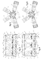
- an aircraft seat according to the present invention is illustrated respectively from the front and rear view of the seat.
- the notions "front” and “rear” are typically identified with respect to the orientation of a passenger installed on the bench in the station of use.
- the bench has a supporting structure 1 supporting a framework 2 providing a tub formed of a seat 3 and a backrest 4 dihedral relative to each other.
- the tub 3.4 is longitudinally extended in a longitudinal extension L of the seat to be able to simultaneously receive a plurality of passengers placed side by side.
- the supporting structure 1 comprises a base 5,5 'comprising two feet 5 and 5' longitudinally distant from each other. Each foot 5, 5 'has a front leg 6 and a rear leg 7 connected to each other at their base by a sole 8 provided with locks 9 for fixing the bench in the use station on a floor of the floor. AC aircraft.
- the supporting structure 1 also comprises longitudinal members carried by the base 5, 5 'while being oriented parallel to the longitudinal extension L of the seat.
- the frame 2 is mounted on the supporting structure 1 via the front spar 10, the rear spar 11 and extensions of the rear legs 7 extending in elevation towards the top of the backrest 4.
- the backrest 4 provided by the frame 2 is mounted on the rear spar 11 via uprights 12 integrated backrest and through the extensions of the rear legs 7 jointly carrying a complementary spar 13 integrated folder 4.
- the seat 3 formed by the frame 2 is pivotally mounted on the front spar 10 at its longitudinally extended front edge.
- the seat 3 is also supported in suspension by energy absorbers 14 placed in engagement on the one hand with the longitudinally extended rear edge of the seat 3 and on the other hand with the backrest 4 overhanging the rear spar 11.
- Classically the energy absorbers 14 provide a restraint of the seat 3 against the forces experienced by the tub 3.4 and generated by at least one passenger received by the seat.
- the energy absorbers 14 are each deformable as a result of the forces supported by the tub 3.4 above a predefined effort threshold.
- each harness 15 has four straps, including two shoulder straps 16,16 'and two pelvic straps 17,17', and a locking member 21 of the straps 16,16 ', 17,17' locking them in the position of looping the harness 15 around a passenger.
- the total number of harnesses 15 equipping the seat, simultaneously associating four straps 16, 16 ', 17, 17' and a locking member 21, defines the optimal number of passenger reception locations on the seat, as number of four on the exemplary embodiment of the illustrated bench.
- each of the harness 15 in two sets of separate straps 16,17 and 16', 17 'each comprising a shoulder strap 16,16' and a pelvic strap 17,17 ', said sets of straps being respectively assigned to the closure of the same passenger at one of its sides.
- the straps 16, 17, 16 ', 17' of each of the harnesses 15 are each individually anchored on the seat at one of their ends, said distal.
- the shoulder straps 16, 16 'of each of the harnesses 15 are preferably anchored on the seat by means of reels 18 mounted on the backrest 4, being returned from the reels 18 towards the front of the seat by through an appendix beam 37 integrated in the file 4.
- the seat 3 is subdivided into a plurality of adjacent seat plates 22 in the longitudinal extension orientation of the seat.
- the seat plates 22 are each individually pivotally mounted on the base 5, 5 'at their front edge by means of the front spar 10.
- the seat plates 22 are also individually supported by suspension at their opposite rear edge by the energy absorbers 14.
- the energy absorbers 14 are each affected, preferably in pairs, to a given base plate 22.
- the individual reception locations of the passengers 23 of the aircraft AC on the seat are each defined by two adjacent seat plates 22 receiving a respective buttock of the passenger 23.
- the plates seat 22 are N in number 1 pair equal to 8.
- the number N 1 of base plates 22 defines an optimal number N 2 of passengers 23 adapted to be received by the seat, the number N 2 being equal to N 1 / 2 is four passengers 23 as shown in a first configuration of reception of passengers 23 on the seat illustrated on the fig.3 .
- the subdivision of the seat 3 into seat plates 22 defining in pairs a passenger location 23 makes it possible to install several passengers 23 on the seat in a second configuration for accommodating passengers 23 on the bench.
- the passengers 23 are in an odd number N 3 equal to three, as shown in FIG. fig.4 .
- the passengers 23 are spaced from each other by a distance equivalent to a seat plate 22, which provides passengers with a spatial comfort 23 by their side.
- Such spatial comfort is provided without structural modification of the seat that may require a specific intervention of the passengers 23 on a body of the bench, other than the usual intervention of the belting of passengers by a harness 15 by locking the straps 16, 16 ' , 17,17 'on the locking member 21.
- the backrest 4 of the seat has a visual cue 19 identifying each of the reception locations defined by the bench.
- the visual cue 19 comprises in particular a marking comprising bands 25,25 'visually identifying a group of two adjacent seat plates 22 and this for all possible groups of two adjacent seat plates 22.
- the marking comprises two end strips 25 'formed at the respective longitudinal ends of the backrest 4 and a median strip 25.
- the middle band 25 is arranged in Y, whose upper side panels 27 define with the end bands 25 'two reception locations 24 of a passenger 23 respectively adjacent to the reception locations. end 20.
- the lower branch 27 'of the median strip 25 visually points a reception area 28 of a passenger 23 formed in the median zone of the seat being separated from each of the end receiving locations 20 by a base plate 22.
- the passengers 23 in number N 2 can be individually surrounded by a harness 15 by exploiting all of said sets of straps (16,17); (16 ', 17') composing two by two a harness 15 given.
- passengers 23 in number N 3 can be individually belted by operating if necessary two sets of straps (16,17); (16 ', 17') adjacent and respective to two adjacent harnesses used according to the first home configuration.
- two passengers 23 installed at the respective longitudinal ends of the seat each operate two harnesses 15 according to the first configuration home.
- a passenger 23 installed in the median area of the seat exploits the sets of straps (16,17); (16 ', 17') adjacent two harnesses 15 neighbors exploitable according to the first home configuration and the locking member 21 of any one of said two neighboring harnesses.
- harnesses 15 are represented on the fig.5 and fig.6 , with the locking member 21 of each of the harnesses 15 which is a locking member 21 with five locking points A, B, C, D, E respectively shown schematically in dashed lines globally each shaped as a triangle.
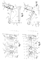
- the energy absorbers 14 are each formed of a rope 29 closed in a loop on itself.
- the rope 29 is placed on the one hand at its proximal end by hooking the buckle on a hook 30 (visible fig.9, fig.10 ) equipping the rear edge of a given seat plate 22 and secondly on the backrest 4 by means of a pulley 32 mounted freely rotating on a bearing 31 supported by the backrest 4, around which pulley 32 the rope 29 is tightly wound.
- the seat On the fig.7 and fig.9 , the seat is in a common position of use in the absence of a strong deceleration of the aircraft AC. On the fig.8 and fig.10 , the seat is in a passenger protection situation 23 due to a sharp deceleration of the AC aircraft causing the actuation of the energy absorbers 14 engaged on the seat plates 22 occupied by the passenger or passengers.
- the winding of the rope around the pulley 32 blocks the rope 29 in a predefined position providing a retention of the seat plate 22 in the absence of strong deceleration of the aircraft.
- a reserve 34 of the rope 29 is formed between the pulley 32 and the distal end of the loop formed by the rope 29.
- the tub 3.4 is subjected to forces greater than a predefined effort threshold, as conventionally in case of strong deceleration of the aircraft.
- Such provisions make it possible to individually protect the passengers 23 installed on two given adjacent seat plates 22, despite the fact that a plurality of passengers 23 are installed on the seat 3 of the seat which is pivotally articulated on the front spar 10 by presenting a seat. substantially continuous plan of installation of passengers 23 on the seat.
- the seat 3 of the seat is foldable towards the backrest 4, from said common position of use of the bench shown on the fig.11 towards an overall flap position of the seat 3 against the backrest 4 illustrated on the fig.12 .
- the front spar 10 and the rear spar 11 are interconnected by cross members 35, including at least two end crosspieces placed at the respective longitudinal ends of the seat 3.
- the cross members 35 are jointly carriers of the front spar 10 and are pivotally articulated on the rear spar 11.
- the front spar 10 is assembled to the base 5,5 'by means of easily reversible attachment, such as by broaching for example, so that the front spar 10 can be separated from the base 5,5' to allow the tilting of the sitting 3 against the backrest 4 as shown on the fig.12 .
- the bench is braced between the front and the rear via the base 5,5 'as in the illustrated embodiment.
- the front spar 10 is pivotally mounted on the front legs 6 themselves attached to the soles 8 by means of said reversible fastening means, to allow a flap of the front legs 6 under the seat 3 when folded against the backrest 4 from relative pivoting movement between the front legs 6 and the front spar 10.
Applications Claiming Priority (1)
| Application Number | Priority Date | Filing Date | Title |
|---|---|---|---|
| FR1402130A FR3026090B1 (fr) | 2014-09-23 | 2014-09-23 | Banquette pour aeronef organisee pour l'accueil d'un nombre variable de passagers |
Publications (2)
| Publication Number | Publication Date |
|---|---|
| EP3000732A1 true EP3000732A1 (de) | 2016-03-30 |
| EP3000732B1 EP3000732B1 (de) | 2017-05-10 |
Family
ID=52102712
Family Applications (1)
| Application Number | Title | Priority Date | Filing Date |
|---|---|---|---|
| EP15183096.5A Active EP3000732B1 (de) | 2014-09-23 | 2015-08-31 | Sitzbank für luftfahrzeug zur aufnahme einer unterschiedlichen anzahl von passagieren |
Country Status (4)
| Country | Link |
|---|---|
| US (1) | US9963235B2 (de) |
| EP (1) | EP3000732B1 (de) |
| CN (1) | CN105438479B (de) |
| FR (1) | FR3026090B1 (de) |
Families Citing this family (3)
| Publication number | Priority date | Publication date | Assignee | Title |
|---|---|---|---|---|
| CN107531329B (zh) * | 2015-03-17 | 2020-05-19 | Be航天公司 | 在滑行、起飞和着陆期间锁定的弹簧加载的座椅底部 |
| US11230382B2 (en) | 2020-02-05 | 2022-01-25 | B/E Aerospace, Inc. | Combined divan aircraft seat for aircraft passenger compartment suites |
| DE102020106037A1 (de) | 2020-03-05 | 2021-09-09 | Zim Flugsitz Gmbh | Fluggastsitz und Sitzreihe |
Citations (17)
| Publication number | Priority date | Publication date | Assignee | Title |
|---|---|---|---|---|
| US2799323A (en) | 1954-05-18 | 1957-07-16 | Joseph A Berg | Self-aligning seat construction |
| EP0423348A1 (de) | 1989-02-23 | 1991-04-24 | Koito Industries, Ltd. | Anordnung eines sitzgestelles zum absorbieren der aufprallenergie |
| EP0433388A1 (de) | 1988-09-08 | 1991-06-26 | Magerik Ltd | Sitz. |
| US5125598A (en) | 1989-12-07 | 1992-06-30 | Bell Helicopter Textron Inc. | Pivoting energy attenuating seat |
| FR2683191A1 (fr) | 1991-10-31 | 1993-05-07 | Israel Aircraft Ind Ltd | Systeme d'attenuation d'energie pour un siege de vehicule. |
| DE4312343A1 (de) | 1993-04-15 | 1994-10-27 | Eurocopter Deutschland | Überlastabsorber in Faserverbundbauweise |
| EP0716980A1 (de) | 1994-12-13 | 1996-06-19 | EUROCOPTER FRANCE, Société Anonyme dite: | Flugzeug-Unfallsitz mit einem Sicherheitsgurt |
| US5657950A (en) | 1995-08-14 | 1997-08-19 | Industrial Technology Research Intitute | Backward-leaning-movement seat leg structure |
| FR2851974A1 (fr) | 2003-03-04 | 2004-09-10 | Eads Sogerma Services | Systeme de retenue pour une personne occupant un siege de vehicule |
| WO2008027832A2 (en) * | 2006-08-28 | 2008-03-06 | Indiana Mills & Manufacturing, Inc. | Configurable restraint system |
| US20080211219A1 (en) | 2007-03-02 | 2008-09-04 | M2K, Llc. | Seat assembly for a vehicle |
| US7594701B2 (en) | 2005-02-18 | 2009-09-29 | Conax Florida Corporation | Troop seat |
| US20090267390A1 (en) | 2008-04-28 | 2009-10-29 | Eurocopter | Crashworthy seat for a vehicle |
| EP2200481A1 (de) | 2007-09-24 | 2010-06-30 | Massachusetts Institute of Technology | Sitz mit 3d-bewegungsschnittstelle |
| US20100270836A1 (en) | 2009-04-28 | 2010-10-28 | Bae Systems Aerospace And Defense Group Inc. | Resettable Seat With Energy Absorber |
| FR2950607A1 (fr) | 2009-09-30 | 2011-04-01 | Eurocopter France | Siege pour appareils volants motorises, integrant des moyens de protection du passager en cas de crash |
| US20130228652A1 (en) | 2012-03-01 | 2013-09-05 | Eurocopter | Aircraft bench provided with crash-protection means |
Family Cites Families (11)
| Publication number | Priority date | Publication date | Assignee | Title |
|---|---|---|---|---|
| US5597139A (en) * | 1994-04-15 | 1997-01-28 | Burns Aerospace Corporation | Convertible passenger seat assembly |
| US6769716B2 (en) * | 2001-01-05 | 2004-08-03 | Ford Global Technologies, Llc | Seat belt restraint system with movable lap belt guides |
| US6749266B2 (en) * | 2001-11-21 | 2004-06-15 | B E Aerospace, Inc. | Locking collar for passenger seat back recline assembly |
| US7144085B2 (en) * | 2002-03-05 | 2006-12-05 | Indiana Mills & Manufacturing, Inc. | Passenger restraint system |
| US6811186B1 (en) * | 2002-03-29 | 2004-11-02 | Lear Corporation | Seat belt adjustment mechanism |
| US7364199B2 (en) * | 2003-12-04 | 2008-04-29 | Takata Seat Belts, Inc. | Configurable vehicle restraint system having variable anchor points |
| US9010865B2 (en) * | 2007-01-05 | 2015-04-21 | Ford Global Technologies, Llc | Automotive vehicle seat system |
| FR2923568B1 (fr) * | 2007-11-08 | 2009-12-04 | Eurocopter France | Dispositif d'aborption d'energie auto-adaptable a la masse supportee |
| CA2677454A1 (en) * | 2008-08-29 | 2010-02-28 | Syntec Seating Solutions, Llc. | Seat assembly for a vehicle |
| DE102013002887A1 (de) * | 2013-02-19 | 2014-08-21 | Airbus Operations Gmbh | Rekonfigurierbare Passagiersitzbank |
| FR3006668B1 (fr) * | 2013-06-10 | 2015-06-26 | Eurocopter France | Siege anti crash et aeronef |
-
2014
- 2014-09-23 FR FR1402130A patent/FR3026090B1/fr active Active
-
2015
- 2015-08-31 EP EP15183096.5A patent/EP3000732B1/de active Active
- 2015-09-21 US US14/859,495 patent/US9963235B2/en active Active
- 2015-09-23 CN CN201510611353.XA patent/CN105438479B/zh active Active
Patent Citations (18)
| Publication number | Priority date | Publication date | Assignee | Title |
|---|---|---|---|---|
| US2799323A (en) | 1954-05-18 | 1957-07-16 | Joseph A Berg | Self-aligning seat construction |
| EP0433388A1 (de) | 1988-09-08 | 1991-06-26 | Magerik Ltd | Sitz. |
| EP0423348A1 (de) | 1989-02-23 | 1991-04-24 | Koito Industries, Ltd. | Anordnung eines sitzgestelles zum absorbieren der aufprallenergie |
| US5125598A (en) | 1989-12-07 | 1992-06-30 | Bell Helicopter Textron Inc. | Pivoting energy attenuating seat |
| FR2683191A1 (fr) | 1991-10-31 | 1993-05-07 | Israel Aircraft Ind Ltd | Systeme d'attenuation d'energie pour un siege de vehicule. |
| DE4312343A1 (de) | 1993-04-15 | 1994-10-27 | Eurocopter Deutschland | Überlastabsorber in Faserverbundbauweise |
| EP0716980A1 (de) | 1994-12-13 | 1996-06-19 | EUROCOPTER FRANCE, Société Anonyme dite: | Flugzeug-Unfallsitz mit einem Sicherheitsgurt |
| US5657950A (en) | 1995-08-14 | 1997-08-19 | Industrial Technology Research Intitute | Backward-leaning-movement seat leg structure |
| FR2851974A1 (fr) | 2003-03-04 | 2004-09-10 | Eads Sogerma Services | Systeme de retenue pour une personne occupant un siege de vehicule |
| US7594701B2 (en) | 2005-02-18 | 2009-09-29 | Conax Florida Corporation | Troop seat |
| WO2008027832A2 (en) * | 2006-08-28 | 2008-03-06 | Indiana Mills & Manufacturing, Inc. | Configurable restraint system |
| EP2069164A2 (de) | 2006-08-28 | 2009-06-17 | Indiana Mills & Manufacturing, Inc. | Einstellbares rückhaltesystem |
| US20080211219A1 (en) | 2007-03-02 | 2008-09-04 | M2K, Llc. | Seat assembly for a vehicle |
| EP2200481A1 (de) | 2007-09-24 | 2010-06-30 | Massachusetts Institute of Technology | Sitz mit 3d-bewegungsschnittstelle |
| US20090267390A1 (en) | 2008-04-28 | 2009-10-29 | Eurocopter | Crashworthy seat for a vehicle |
| US20100270836A1 (en) | 2009-04-28 | 2010-10-28 | Bae Systems Aerospace And Defense Group Inc. | Resettable Seat With Energy Absorber |
| FR2950607A1 (fr) | 2009-09-30 | 2011-04-01 | Eurocopter France | Siege pour appareils volants motorises, integrant des moyens de protection du passager en cas de crash |
| US20130228652A1 (en) | 2012-03-01 | 2013-09-05 | Eurocopter | Aircraft bench provided with crash-protection means |
Non-Patent Citations (1)
| Title |
|---|
| AIRWORTHINESS STANDARDS: NORMAL CATEGORY ROTORCRAFT, 2002 |
Also Published As
| Publication number | Publication date |
|---|---|
| CN105438479A (zh) | 2016-03-30 |
| US9963235B2 (en) | 2018-05-08 |
| FR3026090A1 (fr) | 2016-03-25 |
| CN105438479B (zh) | 2017-05-17 |
| US20160083095A1 (en) | 2016-03-24 |
| FR3026090B1 (fr) | 2017-05-19 |
| EP3000732B1 (de) | 2017-05-10 |
Similar Documents
| Publication | Publication Date | Title |
|---|---|---|
| LU81927A1 (fr) | Structure support pour sieges | |
| EP2154068B1 (de) | Gesicherte schräge Armlehnenanordnung eines Sitzes, Sitz und Einheit aus zwei Sitzen, die mit einer solchen Anordnung ausgestattet sind | |
| EP0659642B1 (de) | Flugzeugsitz insbesondere für einen Drehflügler mit abhängig vom Gewicht des Fluggastes selbsttätig regelbarer energieabsorbierender Vorrichtung | |
| EP2305561B1 (de) | Luftfahrzeugsitz mit Mitteln zum Schützen des Passagiers im Unfallsfall | |
| EP3000732B1 (de) | Sitzbank für luftfahrzeug zur aufnahme einer unterschiedlichen anzahl von passagieren | |
| EP2978633B1 (de) | Fahrzeugsitz ausgestattet mit einem klappbaren element, wie z.b. einem klapptisch | |
| WO2014056859A1 (fr) | Siege auto pour enfant, a assise reglable en hauteur | |
| CN101224716B (zh) | 儿童座椅 | |
| EP3300488B1 (de) | Über ein freiluftkabel zu ziehendes transportfahrzeug und system mit einem fahrzueg solch eines typs | |
| FR3016862A1 (fr) | Banquette pour aeronef comportant des baquets montes individuellement basculants vers le bas et a l'arriere de la banquette en cas de forte deceleration de l'aeronef | |
| BE1017968A6 (fr) | Dispositif de retenue pour enfants pour le transport dans un bus. | |
| WO2015197768A1 (fr) | Systeme elastique de bloquage d'une tablette de siege de vehicule, en particulier d'aeronef | |
| FR2885566A1 (fr) | Banquette a assise modulable dans un vehicule automobile | |
| EP2018293B1 (de) | Verstaubarer sitz, insbesondere für die dritte sitzreihe | |
| EP1001890A1 (de) | Einbauvorrichtung des rückseitigen laderaumes eines fahrzeuginnenraumes | |
| EP3160802B1 (de) | Kraftfahrzeugsitz mit einer gurtführung für einen sicherheitsgurt | |
| FR3092553A1 (fr) | Dispositif de confort à encombrement réduit, notamment pour un passager de véhicule de transport public | |
| EP2819880B1 (de) | Sitz für ein fahrzeug | |
| FR3022875A1 (fr) | Vehicule automobile comportant une banquette quatre places | |
| FR2979861A1 (fr) | Dispositif de siege a dossier sectionnel pour habitacle de vehicule | |
| FR3034062A3 (fr) | Siege de vehicule automobile equipe d'un enrouleur de ceinture de securite | |
| WO2021063665A1 (fr) | Banquette de vehicule | |
| FR3022873A1 (fr) | Guide-sangle de ceinture de securite pour vehicule automobile | |
| FR2974981A1 (fr) | Sac a dos a sangles d'equilibrage coulissantes | |
| FR2757812A1 (fr) | Agencement de siege arriere de vehicule automobile associe a une ceinture de securite |
Legal Events
| Date | Code | Title | Description |
|---|---|---|---|
| PUAI | Public reference made under article 153(3) epc to a published international application that has entered the european phase |
Free format text: ORIGINAL CODE: 0009012 |
|
| AK | Designated contracting states |
Kind code of ref document: A1 Designated state(s): AL AT BE BG CH CY CZ DE DK EE ES FI FR GB GR HR HU IE IS IT LI LT LU LV MC MK MT NL NO PL PT RO RS SE SI SK SM TR |
|
| AX | Request for extension of the european patent |
Extension state: BA ME |
|
| 17P | Request for examination filed |
Effective date: 20160509 |
|
| RBV | Designated contracting states (corrected) |
Designated state(s): AL AT BE BG CH CY CZ DE DK EE ES FI FR GB GR HR HU IE IS IT LI LT LU LV MC MK MT NL NO PL PT RO RS SE SI SK SM TR |
|
| GRAP | Despatch of communication of intention to grant a patent |
Free format text: ORIGINAL CODE: EPIDOSNIGR1 |
|
| INTG | Intention to grant announced |
Effective date: 20161024 |
|
| RIN1 | Information on inventor provided before grant (corrected) |
Inventor name: JOFFRE, JEAN-FRANCOIS Inventor name: ALMEIDA-GONZALEZ, ERNESTO |
|
| GRAS | Grant fee paid |
Free format text: ORIGINAL CODE: EPIDOSNIGR3 |
|
| GRAA | (expected) grant |
Free format text: ORIGINAL CODE: 0009210 |
|
| AK | Designated contracting states |
Kind code of ref document: B1 Designated state(s): AL AT BE BG CH CY CZ DE DK EE ES FI FR GB GR HR HU IE IS IT LI LT LU LV MC MK MT NL NO PL PT RO RS SE SI SK SM TR |
|
| REG | Reference to a national code |
Ref country code: GB Ref legal event code: FG4D Free format text: NOT ENGLISH |
|
| REG | Reference to a national code |
Ref country code: AT Ref legal event code: REF Ref document number: 892032 Country of ref document: AT Kind code of ref document: T Effective date: 20170515 Ref country code: CH Ref legal event code: EP Ref country code: CH Ref legal event code: NV Representative=s name: E. BLUM AND CO. AG PATENT- UND MARKENANWAELTE , CH |
|
| REG | Reference to a national code |
Ref country code: IE Ref legal event code: FG4D Free format text: LANGUAGE OF EP DOCUMENT: FRENCH |
|
| REG | Reference to a national code |
Ref country code: DE Ref legal event code: R096 Ref document number: 602015002632 Country of ref document: DE |
|
| REG | Reference to a national code |
Ref country code: FR Ref legal event code: PLFP Year of fee payment: 3 |
|
| REG | Reference to a national code |
Ref country code: NL Ref legal event code: MP Effective date: 20170510 |
|
| REG | Reference to a national code |
Ref country code: LT Ref legal event code: MG4D |
|
| REG | Reference to a national code |
Ref country code: AT Ref legal event code: MK05 Ref document number: 892032 Country of ref document: AT Kind code of ref document: T Effective date: 20170510 |
|
| PG25 | Lapsed in a contracting state [announced via postgrant information from national office to epo] |
Ref country code: NO Free format text: LAPSE BECAUSE OF FAILURE TO SUBMIT A TRANSLATION OF THE DESCRIPTION OR TO PAY THE FEE WITHIN THE PRESCRIBED TIME-LIMIT Effective date: 20170810 Ref country code: ES Free format text: LAPSE BECAUSE OF FAILURE TO SUBMIT A TRANSLATION OF THE DESCRIPTION OR TO PAY THE FEE WITHIN THE PRESCRIBED TIME-LIMIT Effective date: 20170510 Ref country code: AT Free format text: LAPSE BECAUSE OF FAILURE TO SUBMIT A TRANSLATION OF THE DESCRIPTION OR TO PAY THE FEE WITHIN THE PRESCRIBED TIME-LIMIT Effective date: 20170510 Ref country code: GR Free format text: LAPSE BECAUSE OF FAILURE TO SUBMIT A TRANSLATION OF THE DESCRIPTION OR TO PAY THE FEE WITHIN THE PRESCRIBED TIME-LIMIT Effective date: 20170811 Ref country code: FI Free format text: LAPSE BECAUSE OF FAILURE TO SUBMIT A TRANSLATION OF THE DESCRIPTION OR TO PAY THE FEE WITHIN THE PRESCRIBED TIME-LIMIT Effective date: 20170510 Ref country code: LT Free format text: LAPSE BECAUSE OF FAILURE TO SUBMIT A TRANSLATION OF THE DESCRIPTION OR TO PAY THE FEE WITHIN THE PRESCRIBED TIME-LIMIT Effective date: 20170510 Ref country code: HR Free format text: LAPSE BECAUSE OF FAILURE TO SUBMIT A TRANSLATION OF THE DESCRIPTION OR TO PAY THE FEE WITHIN THE PRESCRIBED TIME-LIMIT Effective date: 20170510 |
|
| PG25 | Lapsed in a contracting state [announced via postgrant information from national office to epo] |
Ref country code: NL Free format text: LAPSE BECAUSE OF FAILURE TO SUBMIT A TRANSLATION OF THE DESCRIPTION OR TO PAY THE FEE WITHIN THE PRESCRIBED TIME-LIMIT Effective date: 20170510 Ref country code: PL Free format text: LAPSE BECAUSE OF FAILURE TO SUBMIT A TRANSLATION OF THE DESCRIPTION OR TO PAY THE FEE WITHIN THE PRESCRIBED TIME-LIMIT Effective date: 20170510 Ref country code: SE Free format text: LAPSE BECAUSE OF FAILURE TO SUBMIT A TRANSLATION OF THE DESCRIPTION OR TO PAY THE FEE WITHIN THE PRESCRIBED TIME-LIMIT Effective date: 20170510 Ref country code: RS Free format text: LAPSE BECAUSE OF FAILURE TO SUBMIT A TRANSLATION OF THE DESCRIPTION OR TO PAY THE FEE WITHIN THE PRESCRIBED TIME-LIMIT Effective date: 20170510 Ref country code: LV Free format text: LAPSE BECAUSE OF FAILURE TO SUBMIT A TRANSLATION OF THE DESCRIPTION OR TO PAY THE FEE WITHIN THE PRESCRIBED TIME-LIMIT Effective date: 20170510 Ref country code: BG Free format text: LAPSE BECAUSE OF FAILURE TO SUBMIT A TRANSLATION OF THE DESCRIPTION OR TO PAY THE FEE WITHIN THE PRESCRIBED TIME-LIMIT Effective date: 20170810 Ref country code: IS Free format text: LAPSE BECAUSE OF FAILURE TO SUBMIT A TRANSLATION OF THE DESCRIPTION OR TO PAY THE FEE WITHIN THE PRESCRIBED TIME-LIMIT Effective date: 20170910 |
|
| PG25 | Lapsed in a contracting state [announced via postgrant information from national office to epo] |
Ref country code: CZ Free format text: LAPSE BECAUSE OF FAILURE TO SUBMIT A TRANSLATION OF THE DESCRIPTION OR TO PAY THE FEE WITHIN THE PRESCRIBED TIME-LIMIT Effective date: 20170510 Ref country code: EE Free format text: LAPSE BECAUSE OF FAILURE TO SUBMIT A TRANSLATION OF THE DESCRIPTION OR TO PAY THE FEE WITHIN THE PRESCRIBED TIME-LIMIT Effective date: 20170510 Ref country code: DK Free format text: LAPSE BECAUSE OF FAILURE TO SUBMIT A TRANSLATION OF THE DESCRIPTION OR TO PAY THE FEE WITHIN THE PRESCRIBED TIME-LIMIT Effective date: 20170510 Ref country code: SK Free format text: LAPSE BECAUSE OF FAILURE TO SUBMIT A TRANSLATION OF THE DESCRIPTION OR TO PAY THE FEE WITHIN THE PRESCRIBED TIME-LIMIT Effective date: 20170510 Ref country code: RO Free format text: LAPSE BECAUSE OF FAILURE TO SUBMIT A TRANSLATION OF THE DESCRIPTION OR TO PAY THE FEE WITHIN THE PRESCRIBED TIME-LIMIT Effective date: 20170510 |
|
| REG | Reference to a national code |
Ref country code: DE Ref legal event code: R097 Ref document number: 602015002632 Country of ref document: DE |
|
| PG25 | Lapsed in a contracting state [announced via postgrant information from national office to epo] |
Ref country code: SM Free format text: LAPSE BECAUSE OF FAILURE TO SUBMIT A TRANSLATION OF THE DESCRIPTION OR TO PAY THE FEE WITHIN THE PRESCRIBED TIME-LIMIT Effective date: 20170510 |
|
| REG | Reference to a national code |
Ref country code: DE Ref legal event code: R119 Ref document number: 602015002632 Country of ref document: DE |
|
| PLBE | No opposition filed within time limit |
Free format text: ORIGINAL CODE: 0009261 |
|
| STAA | Information on the status of an ep patent application or granted ep patent |
Free format text: STATUS: NO OPPOSITION FILED WITHIN TIME LIMIT |
|
| PG25 | Lapsed in a contracting state [announced via postgrant information from national office to epo] |
Ref country code: MC Free format text: LAPSE BECAUSE OF FAILURE TO SUBMIT A TRANSLATION OF THE DESCRIPTION OR TO PAY THE FEE WITHIN THE PRESCRIBED TIME-LIMIT Effective date: 20170510 |
|
| 26N | No opposition filed |
Effective date: 20180213 |
|
| REG | Reference to a national code |
Ref country code: BE Ref legal event code: MM Effective date: 20170831 |
|
| REG | Reference to a national code |
Ref country code: IE Ref legal event code: MM4A |
|
| PG25 | Lapsed in a contracting state [announced via postgrant information from national office to epo] |
Ref country code: SI Free format text: LAPSE BECAUSE OF FAILURE TO SUBMIT A TRANSLATION OF THE DESCRIPTION OR TO PAY THE FEE WITHIN THE PRESCRIBED TIME-LIMIT Effective date: 20170510 |
|
| PG25 | Lapsed in a contracting state [announced via postgrant information from national office to epo] |
Ref country code: LU Free format text: LAPSE BECAUSE OF NON-PAYMENT OF DUE FEES Effective date: 20170831 |
|
| PG25 | Lapsed in a contracting state [announced via postgrant information from national office to epo] |
Ref country code: IE Free format text: LAPSE BECAUSE OF NON-PAYMENT OF DUE FEES Effective date: 20170831 Ref country code: DE Free format text: LAPSE BECAUSE OF NON-PAYMENT OF DUE FEES Effective date: 20180301 |
|
| REG | Reference to a national code |
Ref country code: FR Ref legal event code: PLFP Year of fee payment: 4 |
|
| PG25 | Lapsed in a contracting state [announced via postgrant information from national office to epo] |
Ref country code: BE Free format text: LAPSE BECAUSE OF NON-PAYMENT OF DUE FEES Effective date: 20170831 |
|
| PG25 | Lapsed in a contracting state [announced via postgrant information from national office to epo] |
Ref country code: MT Free format text: LAPSE BECAUSE OF FAILURE TO SUBMIT A TRANSLATION OF THE DESCRIPTION OR TO PAY THE FEE WITHIN THE PRESCRIBED TIME-LIMIT Effective date: 20170510 |
|
| PG25 | Lapsed in a contracting state [announced via postgrant information from national office to epo] |
Ref country code: HU Free format text: LAPSE BECAUSE OF FAILURE TO SUBMIT A TRANSLATION OF THE DESCRIPTION OR TO PAY THE FEE WITHIN THE PRESCRIBED TIME-LIMIT; INVALID AB INITIO Effective date: 20150831 |
|
| PG25 | Lapsed in a contracting state [announced via postgrant information from national office to epo] |
Ref country code: CY Free format text: LAPSE BECAUSE OF FAILURE TO SUBMIT A TRANSLATION OF THE DESCRIPTION OR TO PAY THE FEE WITHIN THE PRESCRIBED TIME-LIMIT Effective date: 20170510 |
|
| PG25 | Lapsed in a contracting state [announced via postgrant information from national office to epo] |
Ref country code: MK Free format text: LAPSE BECAUSE OF FAILURE TO SUBMIT A TRANSLATION OF THE DESCRIPTION OR TO PAY THE FEE WITHIN THE PRESCRIBED TIME-LIMIT Effective date: 20170510 |
|
| PG25 | Lapsed in a contracting state [announced via postgrant information from national office to epo] |
Ref country code: TR Free format text: LAPSE BECAUSE OF FAILURE TO SUBMIT A TRANSLATION OF THE DESCRIPTION OR TO PAY THE FEE WITHIN THE PRESCRIBED TIME-LIMIT Effective date: 20170510 |
|
| GBPC | Gb: european patent ceased through non-payment of renewal fee |
Effective date: 20190831 |
|
| PG25 | Lapsed in a contracting state [announced via postgrant information from national office to epo] |
Ref country code: PT Free format text: LAPSE BECAUSE OF FAILURE TO SUBMIT A TRANSLATION OF THE DESCRIPTION OR TO PAY THE FEE WITHIN THE PRESCRIBED TIME-LIMIT Effective date: 20170510 |
|
| PG25 | Lapsed in a contracting state [announced via postgrant information from national office to epo] |
Ref country code: AL Free format text: LAPSE BECAUSE OF FAILURE TO SUBMIT A TRANSLATION OF THE DESCRIPTION OR TO PAY THE FEE WITHIN THE PRESCRIBED TIME-LIMIT Effective date: 20170510 |
|
| PG25 | Lapsed in a contracting state [announced via postgrant information from national office to epo] |
Ref country code: GB Free format text: LAPSE BECAUSE OF NON-PAYMENT OF DUE FEES Effective date: 20190831 |
|
| P01 | Opt-out of the competence of the unified patent court (upc) registered |
Effective date: 20230530 |
|
| PGFP | Annual fee paid to national office [announced via postgrant information from national office to epo] |
Ref country code: IT Payment date: 20230825 Year of fee payment: 9 Ref country code: CH Payment date: 20230902 Year of fee payment: 9 |
|
| PGFP | Annual fee paid to national office [announced via postgrant information from national office to epo] |
Ref country code: FR Payment date: 20230824 Year of fee payment: 9 |