EP3000732A1 - An aircraft bench organized to receive a variable number of passengers - Google Patents
An aircraft bench organized to receive a variable number of passengers Download PDFInfo
- Publication number
- EP3000732A1 EP3000732A1 EP15183096.5A EP15183096A EP3000732A1 EP 3000732 A1 EP3000732 A1 EP 3000732A1 EP 15183096 A EP15183096 A EP 15183096A EP 3000732 A1 EP3000732 A1 EP 3000732A1
- Authority
- EP
- European Patent Office
- Prior art keywords
- seat
- straps
- spar
- passenger
- bench
- Prior art date
- Legal status (The legal status is an assumption and is not a legal conclusion. Google has not performed a legal analysis and makes no representation as to the accuracy of the status listed.)
- Granted
Links
- 239000006096 absorbing agent Substances 0.000 claims abstract description 71
- 239000000725 suspension Substances 0.000 claims abstract description 8
- 210000001217 buttock Anatomy 0.000 claims abstract description 7
- 210000002414 leg Anatomy 0.000 claims description 13
- 210000001364 upper extremity Anatomy 0.000 claims description 13
- 230000000007 visual effect Effects 0.000 claims description 9
- 230000000903 blocking effect Effects 0.000 claims description 7
- 230000000295 complement effect Effects 0.000 claims description 6
- 230000002441 reversible effect Effects 0.000 claims description 6
- 238000004804 winding Methods 0.000 claims description 6
- 238000000926 separation method Methods 0.000 claims description 5
- 230000014759 maintenance of location Effects 0.000 claims description 4
- PCTMTFRHKVHKIS-BMFZQQSSSA-N (1s,3r,4e,6e,8e,10e,12e,14e,16e,18s,19r,20r,21s,25r,27r,30r,31r,33s,35r,37s,38r)-3-[(2r,3s,4s,5s,6r)-4-amino-3,5-dihydroxy-6-methyloxan-2-yl]oxy-19,25,27,30,31,33,35,37-octahydroxy-18,20,21-trimethyl-23-oxo-22,39-dioxabicyclo[33.3.1]nonatriaconta-4,6,8,10 Chemical compound C1C=C2C[C@@H](OS(O)(=O)=O)CC[C@]2(C)[C@@H]2[C@@H]1[C@@H]1CC[C@H]([C@H](C)CCCC(C)C)[C@@]1(C)CC2.O[C@H]1[C@@H](N)[C@H](O)[C@@H](C)O[C@H]1O[C@H]1/C=C/C=C/C=C/C=C/C=C/C=C/C=C/[C@H](C)[C@@H](O)[C@@H](C)[C@H](C)OC(=O)C[C@H](O)C[C@H](O)CC[C@@H](O)[C@H](O)C[C@H](O)C[C@](O)(C[C@H](O)[C@H]2C(O)=O)O[C@H]2C1 PCTMTFRHKVHKIS-BMFZQQSSSA-N 0.000 claims 2
- 230000004308 accommodation Effects 0.000 claims 1
- 230000000694 effects Effects 0.000 description 12
- 230000006835 compression Effects 0.000 description 9
- 238000007906 compression Methods 0.000 description 9
- 230000008520 organization Effects 0.000 description 4
- 238000010521 absorption reaction Methods 0.000 description 3
- 210000000056 organ Anatomy 0.000 description 3
- 230000008901 benefit Effects 0.000 description 2
- 238000005516 engineering process Methods 0.000 description 2
- 230000006872 improvement Effects 0.000 description 2
- 238000009434 installation Methods 0.000 description 2
- 239000000463 material Substances 0.000 description 2
- 230000004048 modification Effects 0.000 description 2
- 238000012986 modification Methods 0.000 description 2
- 230000002040 relaxant effect Effects 0.000 description 2
- 238000012550 audit Methods 0.000 description 1
- 239000000969 carrier Substances 0.000 description 1
- 230000008859 change Effects 0.000 description 1
- 238000006073 displacement reaction Methods 0.000 description 1
- 239000004744 fabric Substances 0.000 description 1
- 238000002513 implantation Methods 0.000 description 1
- 230000000873 masking effect Effects 0.000 description 1
- 239000007769 metal material Substances 0.000 description 1
- 238000000034 method Methods 0.000 description 1
- 230000003387 muscular Effects 0.000 description 1
- 238000011084 recovery Methods 0.000 description 1
- 230000000717 retained effect Effects 0.000 description 1
- 230000002269 spontaneous effect Effects 0.000 description 1
Images


Classifications
-
- B—PERFORMING OPERATIONS; TRANSPORTING
- B64—AIRCRAFT; AVIATION; COSMONAUTICS
- B64D—EQUIPMENT FOR FITTING IN OR TO AIRCRAFT; FLIGHT SUITS; PARACHUTES; ARRANGEMENTS OR MOUNTING OF POWER PLANTS OR PROPULSION TRANSMISSIONS IN AIRCRAFT
- B64D11/00—Passenger or crew accommodation; Flight-deck installations not otherwise provided for
- B64D11/06—Arrangements of seats, or adaptations or details specially adapted for aircraft seats
- B64D11/062—Belts or other passenger restraint means for passenger seats
-
- B—PERFORMING OPERATIONS; TRANSPORTING
- B64—AIRCRAFT; AVIATION; COSMONAUTICS
- B64D—EQUIPMENT FOR FITTING IN OR TO AIRCRAFT; FLIGHT SUITS; PARACHUTES; ARRANGEMENTS OR MOUNTING OF POWER PLANTS OR PROPULSION TRANSMISSIONS IN AIRCRAFT
- B64D11/00—Passenger or crew accommodation; Flight-deck installations not otherwise provided for
- B64D11/06—Arrangements of seats, or adaptations or details specially adapted for aircraft seats
- B64D11/0619—Arrangements of seats, or adaptations or details specially adapted for aircraft seats with energy absorbing means specially adapted for mitigating impact loads for passenger seats, e.g. at a crash
-
- B—PERFORMING OPERATIONS; TRANSPORTING
- B64—AIRCRAFT; AVIATION; COSMONAUTICS
- B64D—EQUIPMENT FOR FITTING IN OR TO AIRCRAFT; FLIGHT SUITS; PARACHUTES; ARRANGEMENTS OR MOUNTING OF POWER PLANTS OR PROPULSION TRANSMISSIONS IN AIRCRAFT
- B64D11/00—Passenger or crew accommodation; Flight-deck installations not otherwise provided for
- B64D11/06—Arrangements of seats, or adaptations or details specially adapted for aircraft seats
- B64D11/0647—Seats characterised by special upholstery or cushioning features
-
- B—PERFORMING OPERATIONS; TRANSPORTING
- B64—AIRCRAFT; AVIATION; COSMONAUTICS
- B64D—EQUIPMENT FOR FITTING IN OR TO AIRCRAFT; FLIGHT SUITS; PARACHUTES; ARRANGEMENTS OR MOUNTING OF POWER PLANTS OR PROPULSION TRANSMISSIONS IN AIRCRAFT
- B64D11/00—Passenger or crew accommodation; Flight-deck installations not otherwise provided for
- B64D11/06—Arrangements of seats, or adaptations or details specially adapted for aircraft seats
- B64D11/0693—Width modification of seat assemblies, e.g. for class modification
-
- B—PERFORMING OPERATIONS; TRANSPORTING
- B64—AIRCRAFT; AVIATION; COSMONAUTICS
- B64D—EQUIPMENT FOR FITTING IN OR TO AIRCRAFT; FLIGHT SUITS; PARACHUTES; ARRANGEMENTS OR MOUNTING OF POWER PLANTS OR PROPULSION TRANSMISSIONS IN AIRCRAFT
- B64D25/00—Emergency apparatus or devices, not otherwise provided for
- B64D25/02—Supports or holding means for living bodies
- B64D25/06—Harnessing
-
- Y—GENERAL TAGGING OF NEW TECHNOLOGICAL DEVELOPMENTS; GENERAL TAGGING OF CROSS-SECTIONAL TECHNOLOGIES SPANNING OVER SEVERAL SECTIONS OF THE IPC; TECHNICAL SUBJECTS COVERED BY FORMER USPC CROSS-REFERENCE ART COLLECTIONS [XRACs] AND DIGESTS
- Y02—TECHNOLOGIES OR APPLICATIONS FOR MITIGATION OR ADAPTATION AGAINST CLIMATE CHANGE
- Y02T—CLIMATE CHANGE MITIGATION TECHNOLOGIES RELATED TO TRANSPORTATION
- Y02T50/00—Aeronautics or air transport
- Y02T50/40—Weight reduction
Definitions
- the present invention is in the field of seats for aircraft, including rotorcraft, arranged to secure passengers installed on the seats in case of strong deceleration of the aircraft and / or in case of crash.
- the present invention relates more particularly to the structural organization of an aircraft bench seat for accommodating a variable number of passengers in the conditions required to secure the transport of passengers specific to aircraft.
- the seats for aircraft include means of protection of the passengers installed on the seats in the event of strong deceleration of the aircraft and / or in the event of a crash.
- the seats for aircraft are commonly equipped with the provisions below.
- an aircraft seat is commonly equipped with a personal seat harness of a passenger station sitting on the seat.
- the harness comprises a set of straps, currently four in number, including at least two shoulder straps and two pelvic straps.
- the straps are anchored to the seat at one of their ends, incidentally via reels and / or means for adjusting their length, and are each typically provided with a fastener at their other end. .
- the fasteners equipping the straps commonly cooperate with respective locking members integrated in a harness locking member in the harness wrapping position around the passenger to hold station sitting on the seat.
- the locking member conventionally comprises an actuator operable by the passenger to release at least in part the fastening members of the grip exerted on them by the locking members, thereby breaking the closure of the harness around the passenger and to authorize his evacuation out of the seat.
- the aircraft seats are organized to avoid, or at least limit, their deformations under the effect of the deformations of a floor of the aircraft on which the seat is fixed. Such deformations of the floor are notably caused during a crash of the aircraft.
- the architecture of the aircraft seats is organized in order, in the event of a crash, to accompany and / or to compensate for deformations of the floor on which the seats are installed on board the aircraft.
- Such provisions protect passengers by limiting the impact of floor deformations on a seat bucket receiving the passenger or passengers.
- an aircraft seat is equipped with one or more energy absorbers able to absorb the energy induced by the forces to which said bucket is generally subjected in the event of strong deceleration of the aircraft.
- energy absorbers are in particular deformable means at a predetermined force threshold.
- the energy absorbers support in the absence of deformation at least the seat of the seat, or even the entire bucket seat.
- the passenger or passengers installed on the seat are subject to a sharp deceleration of the aircraft.
- the energy absorbers deform when they are subjected to a force greater than said force threshold.
- a variation in the dimensions of the deformable means of the energy absorbers allows mobility at least the seat or the entire tub to protect the passenger or passengers subjected to the strong deceleration of the aircraft .
- the tub is retained by the energy absorbers at least via the seat.
- the benches are obviously provided with several harnesses corresponding to the number of passengers provided according to the optimal passenger reception capacity of the seat.
- the respective locations of implantation of the harnesses on the seat and / or the number of said locking members of the harness in the looping position of the harness around a passenger classically determine the number and locations identifying the seating positions of the seat. seat that can respectively accommodate passengers.
- An aircraft seat commonly comprises a supporting structure supporting a framework.
- the frame home at least one said bucket consists of a seat and a folder receiving one or more passengers.
- the frame is likely to spare several individual passenger tubs or a collective tub that can accommodate several passengers.
- the support structure conventionally comprises a base typically provided with locks for attachment to a floor of the aircraft, in particular by bolting or by cooperation of said locks with rails integrated with the floor of the aircraft.
- the base is carrying the framework through structural elements of the support structure connecting the legs together, such as structural elements formed of uprights and / or spars.
- the energy absorber or absorbers are potentially integrated into the carrier structure, for example being interposed between the base and said structural elements.
- EP0423348 KIGUCHI SHIGERU et al.
- US5657950 IND TECHNOLOGY RESEARCH INT et al.
- the energy absorber or absorbers are potentially interposed between the carrier structure and the frame.
- EP0716980 EUROPTER FRANCE
- US5125598 RG FOX
- US20100270836 GA MOWRY et al.
- the energy absorber is more particularly formed of a spring carried by the seat and placed under stress via a rope.
- the rope is engaged on the spring at one of its ends and on the frame at the other of its ends by means of a pulley around which the rope is wound.
- An advantage of the benches is to accommodate several passengers with a weight and a small footprint of the bench compared to several seats individually receiving the same number of passengers.
- optimizing the number of passengers that can be accommodated by a seat with the smallest possible footprint implies a restriction of the space available on the seat for each passenger, to the detriment of their individual comfort.
- the seat can be occupied by fewer passengers than its optimum capacity.
- the seats of the seat reserved for each of the passengers are predetermined according to the layout of the seat, in the context of the constraints related to securing the passengers on the seat in case of strong deceleration and / or in the event of a crash. the aircraft.
- an aircraft seat includes a support structure provided with fastening means jointly with the floor and a wall of the aircraft.
- the carrier structure is dressed in a fabric providing an overall seat for the reception of several passengers, said canvas being supported by a mesh of straps that can be more or less stretched on the supporting structure.
- a vehicle seat with safety belts can receive a variable number of passengers by moving, along a rail implanted on the seat, locking members of said belts in the looping position.
- the traditional seating of the seats is monobloc and generally receives the buttocks of the users. It has however been found that the comfort of users could be improved by dividing the seat of a seat into two basic seats respectively receiving the buttocks of the user.
- the purpose of the present invention is to provide an aircraft bench seat organized to accommodate a variable number of passengers within the constraints of securing the passengers transported by an aircraft, in particular vis-à-vis vis-a-vis a strong deceleration of the aircraft and / or in case of crash.
- the approach of the present invention is all the more difficult to conduct that it must be considered, given the security of passengers to be provided, the seats available on the seat must be predefined and clearly identifiable by passengers.
- an aircraft seat of the type conventionally comprising a load-bearing structure supporting a frame providing a tub formed of a seat and a backrest.
- the tub has a predefined plurality of individual passenger seating locations.
- the supporting structure comprises a base provided with locks for fixing the seat in the use station.
- a bench use station typically identifies one of its extension dimensions in elevation from the base to the backrest and, in accordance with the posture of a passenger conventionally accommodated by the seat, a front area and a seat. rear area between which the seat extends, the backrest being located in the rear area of the bench.
- the supporting structure also includes longitudinal members, including a "front” qualified spar located at the front of the bench in the use station and a “rear” qualified spar and located at the rear of the bench in the use station. .
- Said front spar and said rear spar are each mounted on the base.
- the frame is pivotally mounted on the supporting structure at least via the seat pivotally mounted on the base via the front spar.
- the aircraft seat of the present invention also comprises a plurality of harnesses in number corresponding to the number passengers can be accommodated simultaneously by the bench.
- Each harness has at least four straps, including two shoulder straps and two pelvic straps.
- the straps are each anchored to the seat at one of their ends and are each lockable at their opposite end on a locking member at predefined locking points according to a looping of a harness around a passenger.
- the locking of the straps in the looping position of a harness around a passenger is achieved by means of a locking member having respective locking points of each of the straps of a given harness. , operated to surround a passenger.
- such a locking member is current and notably comprises locking members identifying said locking points and cooperating respectively with fastening members equipping the straps.
- the respective cooperation by a passenger between the fastening members and the locking members are at least partially able to be broken under the effect of the actuation of an operating member integrated in the locking member.
- the aircraft seat of the present invention further comprises a plurality of energy absorbers engaged on the frame.
- the energy absorbers provide at least a restraint of the seat in case of strong deceleration of the aircraft against the efforts made by the tub and generated by at least one passenger received by the seat.
- Energy absorbers can be classically each arranged as deformable members, that is to say, each is modified in shape such as extension or compression for example, when the forces supported by the tub are greater than a predefined effort threshold.
- the seat of the present invention is mainly recognizable in that it includes the provisions mentioned below.
- the seat is subdivided according to the general extension of the front spar into a plurality of adjacent seat plates.
- the seat plates are in particular each resistant in torsion and flexion vis-à-vis a predefined stress threshold.
- Two adjacent seat plates jointly provide a said individual reception location of a passenger by individual reception of a respective buttock of the passenger.
- the seat plates are each mounted individually pivotally movable on the support structure, being more particularly each mounted individually pivoting on the base at their front edge through the front spar.
- the seat plates are each individually supported in suspension at their opposite rear edge by at least one said energy absorber.
- Said energy absorbers are each assigned to a base plate being placed in engagement with the supporting structure for example, but as referred to below, preferably being placed in engagement with the backrest.
- each of the harnesses in two sets of separate straps each comprising a shoulder strap and a pelvic strap, each set of straps being assigned to the belt of a passenger respectively to one and the other of its sides.
- the straps of a set of straps qualified median and placed adjacent to any two sets of straps qualified neighbors are jointly lockable on the same organ blocking, selectively with one or other of said sets of neighboring straps through respective combinations of locking points of the locking member identified according to the relative position relative to each other games straps cooperating with the same locking member.
- the different sets of straps are cooperating two by two with the same locking member according to the reception locations chosen by the passengers and each comprising two adjacent seat plates.
- Three successively adjacent bedplates identify two by two a number of home locations equal to two.
- three sets of successively adjacent straps and respectively affected two by two to the belt of a passenger to one of its sides, are able to belt a passenger regardless of the location chosen by the passenger operator any 2 adjacent seat plates.
- the flat conformation of the seat plates and a short separation distance between two adjacent seat plates provides a substantially continuous plane of the seating of the seat providing a seating comfort to the passenger regardless of the two. adjacent seat plates that he uses.
- a number N 1 pair of seat plates equipping the seat determines a number N 2 of first passenger reception locations, N 2 being equal to N 1/2 and identifying the optimal number of passengers can be accommodated simultaneously on the bench.
- Said number N2 also corresponds to the optimal number of harnesses that can be simultaneously used by the passengers, said number N2 being in particular identifiable by the number of locking members of the harnesses equipping the seat.
- an N 3 number of second passenger reception locations is defined by operating two adjacent seating plates respectively participating two so-called first neighboring locations.
- the provisions of the invention allow such a gain in space while providing individualized passenger protection, including in the event of strong deceleration of the aircraft causing an individualized deformation of the energy absorbers supporting respectively the seat plates .
- the individualized deformation of the energy absorbers is caused by the passenger's own mass using the base plates supported by the energy absorbers assigned to them.
- the passenger can use any two sets of adjacent straps for his belting by a harness regardless of the two adjacent seat plates he uses, in accordance with his habits by locking the straps on the appropriate temporary locking points of the organ blocking.
- the selective operation by the passenger straps games necessary for its belting is made possible by a simple movement of the locking member used by the passenger.
- Such a displacement of the locking member is operated by the passenger by exploiting the flexibility of the strap permanently locked on the locking member, and by turning the locking member to position in appropriate position the points of locking according to the sets of straps selectively used by the passenger.
- the energy absorbers are potentially individually deformable, such as, for example, in extension or in compression, as conventionally according to the structural organization and / or the modes of engagement of the absorbers. energy respectively on the seat plates and on the supporting structure or on the backrest.
- the energy absorbers can be of any known arrangement, such as arranged in cylinder, in compression spring and / or in an organ comprising a deformable mass for example, the deformation capacity of said deformable mass that can indifferently result from its material and / or its conformation.
- the energy absorbers each comprise a loop closed loop on itself, in particular being resistant to its deformation in extension and / or in compression under the effect of the implementation. of the energy absorber.
- the rope is resistant against its intrinsic deformation extension and / or compression, such as a rope from a metal material for example.
- the characteristics of the rope forming a given energy absorber particularly with regard to the material from which it is derived and / or with regard to its dimensions and / or its conformation, give it an intrinsic resistance to against its deformation in extension and / or in compression.
- said intrinsic resistance of the rope is to be considered when the rope is subjected to a force at least less or equal to or slightly greater than the maximum forces potentially supported by the rope under the effect of the implementation of the absorber of energy in case of strong deceleration of the aircraft.
- said intrinsic resistance of the rope gives it resistance to deformation in extension and / or compression under the effect of the implementation of the energy absorber as a result of the forces supported by the bucket. case of strong deceleration of the aircraft.
- the rope is wound tightly between the ends of said loop formed by the rope around a pulley rotatably mounted on a bearing fixed to the backrest.
- One end of the loop called proximal
- the other end of the loop called distal, is free by being disposed overhanging the pulley in the absence of forces supported by the rope lower than said stress threshold determining the implementation of the energy absorber .
- the rope is provided with means for retaining the distal end of the loop against the pulley at the end of the stroke of the rope caused by the implementation of the energy absorber as a result of the forces supported by the seat plate in case of strong deceleration of the aircraft.
- the loop conformation of a rope forming a given energy absorber induces a winding at least one turn of two strands of the rope around the pulley.
- Said two strands of the rope work together during the implementation of the energy absorber by balancing the forces supported by the pulley along its axis of rotation under the effect of the respective flows of said strands around the pulley.
- the rope When the forces supported by a given baseplate are greater than said predefined force threshold, the rope circulates around the pulley in buttresses, successively deforming by folding and then relaxing, such a deformation of the rope providing the desired energy absorption until the abutment of the rope against the pulley through said retaining means.
- the abutment of the rope against the pulley provided by said retaining means makes it possible to retain the base plate against its tilting caused to the bottom and the back of the seat under the effect of the forces supported by the seat plate on which is installed a passenger.
- the loop conformation of the rope is used to form said retaining means.
- said retaining means is formed by a winding of the rope around the pulley via a knot known as the "lark knot” (cowhitch in English), such a knot. lark closing around the pulley at the distal end of the loop at the end of stroke of the rope caused by the implementation of the energy absorber.
- the energy absorbers are in particular free of elastically deformable means in extension and / or compression often expensive, bulky and massive.
- the individual arrangement of the energy absorbers proposed by the present invention makes it possible to limit the increase in the weight of the seat provided for each of the reception locations of at least two energy absorbers respectively assigned to support two adjacent seat plates together providing a same home location.
- each of the bedplates is capable of being individually supported by a single energy absorber.
- each base plate is supported by at least two energy absorbers, in particular placed at a distance from one another in the vicinity of the respective ends of the rear edge of a plate. given seat.
- Such provisions provide a stable support of the base plate in its general plane maintained parallel to the front spar, and this regardless of the posture taken by the passenger potentially applying different loads respectively on the one and the other seat plates on which the passenger has taken a seat.
- the base conventionally comprises at least two feet each provided with at least one latch for fixing the seat station in use.
- the feet are jointly carrying the front spar and the rear spar and each comprise at least one front leg and at least one rear leg.
- said rear legs advantageously extend in elevation to the top of the backrest and are jointly carrying at least one additional spar integrated backrest.
- the shoulder straps of the set of harnesses are preferably each engaged on individual reels mounted on the backrest.
- said rear legs are preferably jointly carrying an annex spar overhanging the reels.
- the side spar guides the shoulder straps from the backrest to the front of the seat, the rear spar guiding the pelvic straps from the back to the front of the bench.
- the rear spar, the complementary spar and the auxiliary spar advantageously constitute recovery members of the forces supported by the bench.
- the rear spar supports the backrest at its base and resumes the efforts transmitted to the tub by the pelvic straps and the base.
- the complementary spar and the side spar take up the forces transmitted to the tub by the reels and the shoulder straps, as well as transmitted by the energy absorbers and the base.
- the front spar and the rear spar are interconnected by cross members by providing a set of overall tilt from the seat to the backrest.
- the front spar is assembled to the base by reversible attachment means, such as by broaching for example, allowing a separation or alternatively a fast and easy connection of the front spar vis-à-vis the base.
- the seat is generally foldable towards the backrest despite its subdivision into a plurality of individually mounted pivoting seat plates on the front spar, by separating the front spar vis-à-vis the base and pivoting the seat around the spar back through the sleepers.
- the seat plates being individually supported by the deformable energy absorbers, such as advantageously arranged in a line wrapped around said pulley, securing the passengers provided by the energy absorbers does not obstruct the overall flap of the seat to the backrest by pivoting the sleepers around the rear spar.
- the front spar and the front legs are pivotally mounted relative to each other.
- the front legs are assembled to respective soles of the feet via the reversible fastening means.
- Said soles are conventionally equipped with latches for fixing the bench in the use station.
- the seat is preferably braced between the front and rear through the base.
- the front legs and the rear legs comprise crutches connecting the soles respectively the front spar and the rear spar.
- At least the folder advantageously includes a visual cue identifying the individual passenger locations.
- Said reception locations are individually identified by a marking forming at least partly the visual cue, said marking visually identifying a group of two adjacent base plates and for all possible groups of two adjacent base plates usable by a passenger to settle on the bench.
- the visual cue comprises a marking composed of at least one set of strips visually separating the reception locations of the seat respectively located from on each side of the strips and each comprising a first group of two adjacent seat plates and distinct from one to the other of said receiving locations located on either side of the bands.
- At least one band of the set of strips visually points an adjacency zone between two adjacent seating plates of a second group forming a reception location, the seating plates of the second group comprising a plate of sitting of each of the first groups.
- reference AC designates an aircraft according to the invention.
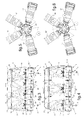
- an aircraft seat according to the present invention is illustrated respectively from the front and rear view of the seat.
- the notions "front” and “rear” are typically identified with respect to the orientation of a passenger installed on the bench in the station of use.
- the bench has a supporting structure 1 supporting a framework 2 providing a tub formed of a seat 3 and a backrest 4 dihedral relative to each other.
- the tub 3.4 is longitudinally extended in a longitudinal extension L of the seat to be able to simultaneously receive a plurality of passengers placed side by side.
- the supporting structure 1 comprises a base 5,5 'comprising two feet 5 and 5' longitudinally distant from each other. Each foot 5, 5 'has a front leg 6 and a rear leg 7 connected to each other at their base by a sole 8 provided with locks 9 for fixing the bench in the use station on a floor of the floor. AC aircraft.
- the supporting structure 1 also comprises longitudinal members carried by the base 5, 5 'while being oriented parallel to the longitudinal extension L of the seat.
- the frame 2 is mounted on the supporting structure 1 via the front spar 10, the rear spar 11 and extensions of the rear legs 7 extending in elevation towards the top of the backrest 4.
- the backrest 4 provided by the frame 2 is mounted on the rear spar 11 via uprights 12 integrated backrest and through the extensions of the rear legs 7 jointly carrying a complementary spar 13 integrated folder 4.
- the seat 3 formed by the frame 2 is pivotally mounted on the front spar 10 at its longitudinally extended front edge.
- the seat 3 is also supported in suspension by energy absorbers 14 placed in engagement on the one hand with the longitudinally extended rear edge of the seat 3 and on the other hand with the backrest 4 overhanging the rear spar 11.
- Classically the energy absorbers 14 provide a restraint of the seat 3 against the forces experienced by the tub 3.4 and generated by at least one passenger received by the seat.
- the energy absorbers 14 are each deformable as a result of the forces supported by the tub 3.4 above a predefined effort threshold.
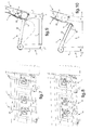
- each harness 15 has four straps, including two shoulder straps 16,16 'and two pelvic straps 17,17', and a locking member 21 of the straps 16,16 ', 17,17' locking them in the position of looping the harness 15 around a passenger.
- the total number of harnesses 15 equipping the seat, simultaneously associating four straps 16, 16 ', 17, 17' and a locking member 21, defines the optimal number of passenger reception locations on the seat, as number of four on the exemplary embodiment of the illustrated bench.
- each of the harness 15 in two sets of separate straps 16,17 and 16', 17 'each comprising a shoulder strap 16,16' and a pelvic strap 17,17 ', said sets of straps being respectively assigned to the closure of the same passenger at one of its sides.
- the straps 16, 17, 16 ', 17' of each of the harnesses 15 are each individually anchored on the seat at one of their ends, said distal.
- the shoulder straps 16, 16 'of each of the harnesses 15 are preferably anchored on the seat by means of reels 18 mounted on the backrest 4, being returned from the reels 18 towards the front of the seat by through an appendix beam 37 integrated in the file 4.
- the seat 3 is subdivided into a plurality of adjacent seat plates 22 in the longitudinal extension orientation of the seat.
- the seat plates 22 are each individually pivotally mounted on the base 5, 5 'at their front edge by means of the front spar 10.
- the seat plates 22 are also individually supported by suspension at their opposite rear edge by the energy absorbers 14.
- the energy absorbers 14 are each affected, preferably in pairs, to a given base plate 22.
- the individual reception locations of the passengers 23 of the aircraft AC on the seat are each defined by two adjacent seat plates 22 receiving a respective buttock of the passenger 23.
- the plates seat 22 are N in number 1 pair equal to 8.
- the number N 1 of base plates 22 defines an optimal number N 2 of passengers 23 adapted to be received by the seat, the number N 2 being equal to N 1 / 2 is four passengers 23 as shown in a first configuration of reception of passengers 23 on the seat illustrated on the fig.3 .
- the subdivision of the seat 3 into seat plates 22 defining in pairs a passenger location 23 makes it possible to install several passengers 23 on the seat in a second configuration for accommodating passengers 23 on the bench.
- the passengers 23 are in an odd number N 3 equal to three, as shown in FIG. fig.4 .
- the passengers 23 are spaced from each other by a distance equivalent to a seat plate 22, which provides passengers with a spatial comfort 23 by their side.
- Such spatial comfort is provided without structural modification of the seat that may require a specific intervention of the passengers 23 on a body of the bench, other than the usual intervention of the belting of passengers by a harness 15 by locking the straps 16, 16 ' , 17,17 'on the locking member 21.
- the backrest 4 of the seat has a visual cue 19 identifying each of the reception locations defined by the bench.
- the visual cue 19 comprises in particular a marking comprising bands 25,25 'visually identifying a group of two adjacent seat plates 22 and this for all possible groups of two adjacent seat plates 22.
- the marking comprises two end strips 25 'formed at the respective longitudinal ends of the backrest 4 and a median strip 25.
- the middle band 25 is arranged in Y, whose upper side panels 27 define with the end bands 25 'two reception locations 24 of a passenger 23 respectively adjacent to the reception locations. end 20.
- the lower branch 27 'of the median strip 25 visually points a reception area 28 of a passenger 23 formed in the median zone of the seat being separated from each of the end receiving locations 20 by a base plate 22.
- the passengers 23 in number N 2 can be individually surrounded by a harness 15 by exploiting all of said sets of straps (16,17); (16 ', 17') composing two by two a harness 15 given.
- passengers 23 in number N 3 can be individually belted by operating if necessary two sets of straps (16,17); (16 ', 17') adjacent and respective to two adjacent harnesses used according to the first home configuration.
- two passengers 23 installed at the respective longitudinal ends of the seat each operate two harnesses 15 according to the first configuration home.
- a passenger 23 installed in the median area of the seat exploits the sets of straps (16,17); (16 ', 17') adjacent two harnesses 15 neighbors exploitable according to the first home configuration and the locking member 21 of any one of said two neighboring harnesses.
- harnesses 15 are represented on the fig.5 and fig.6 , with the locking member 21 of each of the harnesses 15 which is a locking member 21 with five locking points A, B, C, D, E respectively shown schematically in dashed lines globally each shaped as a triangle.
- the energy absorbers 14 are each formed of a rope 29 closed in a loop on itself.
- the rope 29 is placed on the one hand at its proximal end by hooking the buckle on a hook 30 (visible fig.9, fig.10 ) equipping the rear edge of a given seat plate 22 and secondly on the backrest 4 by means of a pulley 32 mounted freely rotating on a bearing 31 supported by the backrest 4, around which pulley 32 the rope 29 is tightly wound.
- the seat On the fig.7 and fig.9 , the seat is in a common position of use in the absence of a strong deceleration of the aircraft AC. On the fig.8 and fig.10 , the seat is in a passenger protection situation 23 due to a sharp deceleration of the AC aircraft causing the actuation of the energy absorbers 14 engaged on the seat plates 22 occupied by the passenger or passengers.
- the winding of the rope around the pulley 32 blocks the rope 29 in a predefined position providing a retention of the seat plate 22 in the absence of strong deceleration of the aircraft.
- a reserve 34 of the rope 29 is formed between the pulley 32 and the distal end of the loop formed by the rope 29.
- the tub 3.4 is subjected to forces greater than a predefined effort threshold, as conventionally in case of strong deceleration of the aircraft.
- Such provisions make it possible to individually protect the passengers 23 installed on two given adjacent seat plates 22, despite the fact that a plurality of passengers 23 are installed on the seat 3 of the seat which is pivotally articulated on the front spar 10 by presenting a seat. substantially continuous plan of installation of passengers 23 on the seat.
- the seat 3 of the seat is foldable towards the backrest 4, from said common position of use of the bench shown on the fig.11 towards an overall flap position of the seat 3 against the backrest 4 illustrated on the fig.12 .
- the front spar 10 and the rear spar 11 are interconnected by cross members 35, including at least two end crosspieces placed at the respective longitudinal ends of the seat 3.
- the cross members 35 are jointly carriers of the front spar 10 and are pivotally articulated on the rear spar 11.
- the front spar 10 is assembled to the base 5,5 'by means of easily reversible attachment, such as by broaching for example, so that the front spar 10 can be separated from the base 5,5' to allow the tilting of the sitting 3 against the backrest 4 as shown on the fig.12 .
- the bench is braced between the front and the rear via the base 5,5 'as in the illustrated embodiment.
- the front spar 10 is pivotally mounted on the front legs 6 themselves attached to the soles 8 by means of said reversible fastening means, to allow a flap of the front legs 6 under the seat 3 when folded against the backrest 4 from relative pivoting movement between the front legs 6 and the front spar 10.
Landscapes
- Engineering & Computer Science (AREA)
- Aviation & Aerospace Engineering (AREA)
- Business, Economics & Management (AREA)
- Emergency Management (AREA)
- Seats For Vehicles (AREA)
- Automotive Seat Belt Assembly (AREA)
- Chair Legs, Seat Parts, And Backrests (AREA)
Abstract
La présente invention a pour objet une banquette pour aéronef comportant des emplacements d'accueil chacun définis par deux plaques d'assise (22) recevant une fesse respective d'un passager. Les plaques d'assise (22) sont chacune individuellement montées mobiles en pivotement sur un longeron avant (10) de la banquette en étant chacune individuellement soutenues en suspension à leur bord arrière par des absorbeurs d'énergie (14). La banquette est équipée d'une pluralité de jeux de sangles (16,17 ; 16',17') adjacents verrouillables deux à deux sur un organe de blocage (21), dont les points de verrouillage sont sélectivement exploités pour ceinturer un passager selon l'emplacement d'accueil choisi par le passager.

Description
La présente invention est du domaine des sièges pour aéronefs, giravions notamment, agencés pour sécuriser les passagers installés sur les sièges en cas de forte décélération de l'aéronef et/ou en cas de crash.The present invention is in the field of seats for aircraft, including rotorcraft, arranged to secure passengers installed on the seats in case of strong deceleration of the aircraft and / or in case of crash.
La présente invention relève plus particulièrement de l'organisation structurelle d'une banquette pour aéronefs permettant d'accueillir un nombre variable de passagers dans les conditions requises de sécurisation du transport des passagers propres aux aéronefs.The present invention relates more particularly to the structural organization of an aircraft bench seat for accommodating a variable number of passengers in the conditions required to secure the transport of passengers specific to aircraft.
Les sièges pour aéronefs comportent des moyens de protection des passagers installés sur les sièges en cas de forte décélération de l'aéronef et/ou en cas de crash. A cet effet, les sièges pour aéronefs sont couramment équipés des dispositions ci-après énoncées.The seats for aircraft include means of protection of the passengers installed on the seats in the event of strong deceleration of the aircraft and / or in the event of a crash. For this purpose, the seats for aircraft are commonly equipped with the provisions below.
En premier lieu, un siège pour aéronef est couramment équipé d'un harnais de maintien individuel d'un passager en station assis sur le siège. Le harnais comporte un jeu de sangles, couramment au nombre de quatre, dont au moins deux sangles d'épaule et deux sangles pelviennes. Les sangles sont ancrées sur le siège à l'une de leurs extrémités, accessoirement par l'intermédiaire d'enrouleurs et/ou de moyens de réglage de leur longueur, et sont chacune typiquement munies d'un organe d'attache à leur autre extrémité.Firstly, an aircraft seat is commonly equipped with a personal seat harness of a passenger station sitting on the seat. The harness comprises a set of straps, currently four in number, including at least two shoulder straps and two pelvic straps. The straps are anchored to the seat at one of their ends, incidentally via reels and / or means for adjusting their length, and are each typically provided with a fastener at their other end. .
Les organes d'attache équipant les sangles coopèrent couramment avec des organes de verrouillage respectifs intégrés à un organe de blocage du harnais en position de bouclage du harnais autour du passager pour le retenir en station assis sur le siège.The fasteners equipping the straps commonly cooperate with respective locking members integrated in a harness locking member in the harness wrapping position around the passenger to hold station sitting on the seat.
L'organe de blocage comporte classiquement un actionneur manoeuvrable par le passager pour libérer au moins en partie les organes d'attache de l'emprise exercée sur eux par les organes de verrouillage, ce qui permet de rompre le bouclage du harnais autour du passager et d'autoriser son évacuation hors du siège.The locking member conventionally comprises an actuator operable by the passenger to release at least in part the fastening members of the grip exerted on them by the locking members, thereby breaking the closure of the harness around the passenger and to authorize his evacuation out of the seat.
Concernant l'organisation de tels harnais équipant les sièges d'aéronefs, on pourra par exemple se reporter au document
En deuxième lieu, les sièges d'aéronef sont organisés pour éviter, ou tout au moins limiter, leurs déformations sous l'effet des déformations d'un plancher de l'aéronef sur lequel est fixé le siège. De telles déformations du plancher sont notamment provoquées lors d'un crash de l'aéronef. A cet effet, l'architecture des sièges pour aéronef est organisée pour, en cas de crash, accompagner et/ou pour compenser des déformations du plancher sur lequel les sièges sont installés à bord de l'aéronef. De telles dispositions permettent de protéger les passagers en limitant l'impact des déformations du plancher sur un baquet du siège recevant le ou les passagers.Secondly, the aircraft seats are organized to avoid, or at least limit, their deformations under the effect of the deformations of a floor of the aircraft on which the seat is fixed. Such deformations of the floor are notably caused during a crash of the aircraft. For this purpose, the architecture of the aircraft seats is organized in order, in the event of a crash, to accompany and / or to compensate for deformations of the floor on which the seats are installed on board the aircraft. Such provisions protect passengers by limiting the impact of floor deformations on a seat bucket receiving the passenger or passengers.
En troisième lieu, un siège d'aéronef est équipé d'un ou de plusieurs absorbeurs d'énergie aptes à absorber l'énergie induite par les efforts auxquels ledit baquet est globalement soumis en cas de forte décélération de l'aéronef. De tels absorbeurs d'énergie sont notamment des moyens déformables à un seuil d'effort prédéterminé.Third, an aircraft seat is equipped with one or more energy absorbers able to absorb the energy induced by the forces to which said bucket is generally subjected in the event of strong deceleration of the aircraft. Such energy absorbers are in particular deformable means at a predetermined force threshold.
Plus particulièrement il est à considérer une situation commune d'utilisation d'un siège pour aéronef selon laquelle le ou les passagers installés sur le siège ne subissent pas les effets d'une forte décélération de l'aéronef. Dans une telle situation, les absorbeurs d'énergie soutiennent en l'absence de déformation au moins l'assise du siège, voire la totalité du baquet du siège.More particularly it is to consider a common situation of use of an aircraft seat according to which the seat or passengers installed on the seat do not suffer the effects of a sharp deceleration of the aircraft. In such a situation, the energy absorbers support in the absence of deformation at least the seat of the seat, or even the entire bucket seat.
Dans une situation critique d'utilisation du siège, le ou les passagers installés sur le siège sont soumis à une forte décélération de l'aéronef. Sous l'effet de la charge subie par le baquet supportant la masse du ou des passagers, les absorbeurs d'énergie se déforment lorsqu'ils sont soumis à un effort supérieur audit seuil d'effort. Une variation de dimensions des moyens déformables des absorbeurs d'énergie, indifféremment en compression ou en élongation, autorise une mobilité au moins de l'assise voire de la totalité du baquet pour protéger le ou les passagers soumis à la forte décélération de l'aéronef. En fin de course de déformation des absorbeurs d'énergie, le baquet est retenu par les absorbeurs d'énergie au moins par l'intermédiaire de l'assise.In a critical situation of use of the seat, the passenger or passengers installed on the seat are subject to a sharp deceleration of the aircraft. Under the effect of the load incurred by the tub supporting the weight of the passenger or passengers, the energy absorbers deform when they are subjected to a force greater than said force threshold. A variation in the dimensions of the deformable means of the energy absorbers, regardless of compression or elongation, allows mobility at least the seat or the entire tub to protect the passenger or passengers subjected to the strong deceleration of the aircraft . At the end of the deformation stroke of the energy absorbers, the tub is retained by the energy absorbers at least via the seat.
On pourra par exemple se reporter à ce propos aux documents
Parmi les sièges pour aéronef, il est connu des sièges monoplaces, tels que ceux utilisés par les pilotes par exemple, et des banquettes dédiées à l'accueil de plusieurs passagers.Among the seats for aircraft, it is known single-seat seats, such as those used by pilots for example, and benches dedicated to the reception of several passengers.
Pour ce qui est des banquettes, celles-ci sont bien évidemment munies de plusieurs harnais en nombre correspondant avec le nombre de passagers prévus selon la capacité optimale d'accueil en passagers de la banquette. Les emplacements respectifs d'implantation des harnais sur la banquette et/ou le nombre de dits organes de blocage du harnais en position de bouclage du harnais autour d'un passager, déterminent classiquement le nombre et les emplacements identifiant les places d'assise de la banquette pouvant respectivement accueillir des passagers.As for the benches, they are obviously provided with several harnesses corresponding to the number of passengers provided according to the optimal passenger reception capacity of the seat. The respective locations of implantation of the harnesses on the seat and / or the number of said locking members of the harness in the looping position of the harness around a passenger, classically determine the number and locations identifying the seating positions of the seat. seat that can respectively accommodate passengers.
Une banquette d'aéronef comporte couramment une structure porteuse soutenant une ossature. L'ossature ménage au moins un dit baquet composé d'une assise et d'un dossier recevant un ou plusieurs passagers. L'ossature est susceptible de ménager plusieurs baquets d'accueil individuel des passagers ou un baquet collectif pouvant accueillir conjointement plusieurs passagers.An aircraft seat commonly comprises a supporting structure supporting a framework. The frame home at least one said bucket consists of a seat and a folder receiving one or more passengers. The frame is likely to spare several individual passenger tubs or a collective tub that can accommodate several passengers.
La structure porteuse comporte classiquement un piètement typiquement muni de verrous pour sa fixation à un plancher de l'aéronef, notamment par boulonnage ou par coopération desdits verrous avec des rails intégrés au plancher de l'aéronef. Le piètement est porteur de l'ossature par l'intermédiaire d'éléments structurels de la structure porteuse reliant les piètements entre eux, tels que des éléments structurels formés de montants et/ou de longerons.The support structure conventionally comprises a base typically provided with locks for attachment to a floor of the aircraft, in particular by bolting or by cooperation of said locks with rails integrated with the floor of the aircraft. The base is carrying the framework through structural elements of the support structure connecting the legs together, such as structural elements formed of uprights and / or spars.
Le ou les absorbeurs d'énergie sont potentiellement intégrés à la structure porteuse, en étant par exemple interposés entre le piètement et lesdits éléments structurels. On pourra à ce propos se reporter par exemple aux documents
Par exemple encore, le ou les absorbeurs d'énergie sont potentiellement interposés entre la structure porteuse et l'ossature. On pourra à ce propos se reporter par exemple aux documents
Concernant le document
Un avantage des banquettes est de permettre l'accueil de plusieurs passagers avec une masse et un encombrement réduits de la banquette par rapport à plusieurs sièges recevant individuellement le même nombre de passagers. Cependant l'optimisation du nombre de passagers pouvant être accueillis par une banquette d'un encombrement le plus faible possible implique une restriction de l'espace disponible sur la banquette pour chacun des passagers, au détriment de leur confort individuel.An advantage of the benches is to accommodate several passengers with a weight and a small footprint of the bench compared to several seats individually receiving the same number of passengers. However optimizing the number of passengers that can be accommodated by a seat with the smallest possible footprint implies a restriction of the space available on the seat for each passenger, to the detriment of their individual comfort.
Dans ce contexte, il est constaté que la banquette peut être occupée par des passagers en nombre inférieur à celui de sa capacité d'accueil optimale. Cependant, les emplacements de la banquette réservés à chacun des passagers sont prédéterminés selon l'agencement de la banquette, dans le cadre des contraintes liées à la sécurisation des passagers installés sur la banquette en cas de forte décélération et/ou en cas de crash de l'aéronef.In this context, it is found that the seat can be occupied by fewer passengers than its optimum capacity. However, the seats of the seat reserved for each of the passengers are predetermined according to the layout of the seat, in the context of the constraints related to securing the passengers on the seat in case of strong deceleration and / or in the event of a crash. the aircraft.
Dans ces conditions, l'amélioration du confort individuel des passagers en nombre inférieur à la capacité globale d'accueil de la banquette est restreinte et mérite d'être développée. Il est à relever qu'une telle amélioration doit prendre en compte une recherche constante d'un allègement de la banquette permettant de réduire au mieux sa masse, ce qui est important en aéronautique, ainsi que, tel que précédemment visé, doit prendre en compte une sécurisation des passagers vis-à-vis d'une forte décélération de l'aéronef et/ou en cas de crash.In these conditions, the improvement of individual passenger comfort in a number less than the overall capacity of the seat is limited and deserves to be developed. It should be noted that such an improvement must take into account a constant search for a relief of the bench to reduce its mass at best, which is important in aeronautics, as well as, as previously mentioned, must take into account a security of the passengers vis-à-vis a strong deceleration of the aircraft and / or in case of crash.
Dans le domaine général du transport de passagers à bord des véhicules, il a été proposé des banquettes recherchées légères, voire adaptables, pouvant accueillir un nombre variable de passagers.In the general field of passenger transport in vehicles, it has been proposed light seats sought or adaptable, which can accommodate a variable number of passengers.
Par exemple selon le document
Selon ce document
Par exemple encore selon le document
Toujours au regard du confort des utilisateurs de sièges, l'assise traditionnelle des sièges est monobloc et reçoit globalement le fessier des utilisateurs. Il a cependant été constaté que le confort des utilisateurs pouvait être amélioré en subdivisant l'assise d'un siège en deux assises élémentaires recevant respectivement l'une et l'autre des fesses de l'utilisateur.Always with regard to the comfort of the seat users, the traditional seating of the seats is monobloc and generally receives the buttocks of the users. It has however been found that the comfort of users could be improved by dividing the seat of a seat into two basic seats respectively receiving the buttocks of the user.
On pourra se reporter à ce propos aux sièges décrits par les documents
Selon les documents
D'autres documents ont été considérés, à savoir la spécification
Dans ce contexte, le but de la présente invention est de proposer une banquette pour aéronef organisée pour l'accueil d'un nombre variable de passagers dans le cadre des contraintes d'une sécurisation des passagers transportés par un aéronef, notamment vis-à-vis d'une forte décélération de l'aéronef et/ou en cas de crash.In this context, the purpose of the present invention is to provide an aircraft bench seat organized to accommodate a variable number of passengers within the constraints of securing the passengers transported by an aircraft, in particular vis-à-vis vis-a-vis a strong deceleration of the aircraft and / or in case of crash.
Il est plus particulièrement recherché par la présente invention de proposer une telle banquette pour aéronef dont l'organisation permet d'accueillir un nombre variable de passagers en améliorant significativement leur confort, notamment vis-à-vis de l'écart entre les passagers installés sur la banquette, lorsque les passagers sont en nombre moindre vis-à-vis du nombre optimal de places d'accueil des passagers sur la banquette.It is more particularly sought by the present invention to provide such a bench for aircraft whose organization can accommodate a variable number of passengers significantly improving their comfort, particularly vis-à-vis the gap between the passengers installed on the seat, when passengers are less in number vis-à-vis the optimal number of passenger seats on the seat.
La démarche de la présente invention est d'autant plus délicate à mener qu'il doit être considéré, compte tenu de la sécurisation des passagers devant être procurée, que les places disponibles sur la banquette doivent être prédéfinies et clairement identifiables par les passagers.The approach of the present invention is all the more difficult to conduct that it must be considered, given the security of passengers to be provided, the seats available on the seat must be predefined and clearly identifiable by passengers.
Il doit aussi être considéré la possible installation sur la banquette de passagers en nombre impair pour une banquette comportant un nombre optimal de places d'accueil des passagers en nombre pair, et vice versa. Une telle difficulté est d'autant plus délicate à surmonter dans le cas où le nombre de passagers installés sur la banquette est inférieur d'un seul passager au regard du nombre total de places d'accueil de la banquette.It should also be considered the possible installation on the passenger seat in odd number for a seat with an optimal number of passenger seats in even number, and vice versa. Such a difficulty is all the more difficult to overcome in the case where the number of passengers on the seat is less than a single passenger compared to the total number of seats of the bench.
Il ne doit aussi pas être perdu de vue qu'il est à éviter d'accroître la masse globale de la banquette et de complexifier sa structure outre mesure pour maintenir une obtention et une exploitation de la banquette à des coûts industriellement acceptables. Il est encore recherché dans ce contexte de procurer ledit accueil d'un nombre variable de passagers par la banquette en évitant de modifier l'agencement de la banquette en fonction du nombre de passagers temporairement accueillis.It must also be borne in mind that the overall weight of the bench should not be increased and the structure of the bench should be made more complex in order to maintain obtaining and operating the bench at industrially acceptable costs. It is still sought in this context to provide said reception of a variable number of passengers by the seat in avoiding to modify the layout of the bench depending on the number of passengers temporarily accommodated.
Par ailleurs, il est souhaitable que les dispositions prévues pour améliorer le confort des passagers ne fassent pas obstacle à la possibilité de rabattre la ou les assises vers les dossiers, pour limiter l'encombrement de la banquette en l'absence de passagers.Furthermore, it is desirable that the provisions provided to improve the comfort of passengers do not prevent the possibility of folding the seat or seats to the backs, to limit the size of the seat in the absence of passengers.
Dans cet environnement technologique, il est proposé par la présente invention une banquette pour aéronef du type comportant classiquement une structure porteuse soutenant une ossature ménageant un baquet formé d'une assise et d'un dossier. Le baquet comporte une pluralité prédéfinie d'emplacements d'accueil individuel de passagers.In this technological environment, it is proposed by the present invention an aircraft seat of the type conventionally comprising a load-bearing structure supporting a frame providing a tub formed of a seat and a backrest. The tub has a predefined plurality of individual passenger seating locations.
La structure porteuse comprend un piètement muni de verrous de fixation de la banquette en station d'utilisation. Une telle station d'utilisation de la banquette identifie typiquement l'une de ses dimensions d'extension en élévation depuis le piètement vers le dossier ainsi que, conformément à la posture d'un passager classiquement accueilli par la banquette, une zone avant et une zone arrière entre lesquelles s'étend l'assise, le dossier étant situé en zone arrière de la banquette.The supporting structure comprises a base provided with locks for fixing the seat in the use station. Such a bench use station typically identifies one of its extension dimensions in elevation from the base to the backrest and, in accordance with the posture of a passenger conventionally accommodated by the seat, a front area and a seat. rear area between which the seat extends, the backrest being located in the rear area of the bench.
La structure porteuse comprend encore des longerons, dont un longeron qualifié « avant » et situé à l'avant de la banquette en station d'utilisation et un longeron qualifié « arrière » et situé à l'arrière de la banquette en station d'utilisation. Ledit longeron avant et ledit longeron arrière sont chacun montés sur le piètement. L'ossature est montée pivotante sur la structure porteuse au moins par l'intermédiaire de l'assise montée pivotante sur le piètement par l'intermédiaire du longeron avant.The supporting structure also includes longitudinal members, including a "front" qualified spar located at the front of the bench in the use station and a "rear" qualified spar and located at the rear of the bench in the use station. . Said front spar and said rear spar are each mounted on the base. The frame is pivotally mounted on the supporting structure at least via the seat pivotally mounted on the base via the front spar.
La banquette pour aéronef de la présente invention comporte aussi une pluralité de harnais en nombre correspondant au nombre optimal de passagers pouvant être accueillis simultanément par la banquette. Chaque harnais comporte au moins quatre sangles, dont deux sangles d'épaule et deux sangles pelviennes. Les sangles sont chacune ancrées sur la banquette à l'une de leurs extrémités et sont chacune verrouillables à leur extrémité opposée sur un organe de blocage en des points de verrouillages prédéfinis conformément à un bouclage d'un harnais autour d'un passager.The aircraft seat of the present invention also comprises a plurality of harnesses in number corresponding to the number passengers can be accommodated simultaneously by the bench. Each harness has at least four straps, including two shoulder straps and two pelvic straps. The straps are each anchored to the seat at one of their ends and are each lockable at their opposite end on a locking member at predefined locking points according to a looping of a harness around a passenger.
Plus particulièrement tel que classiquement, le verrouillage des sangles en position de bouclage d'un harnais autour d'un passager est réalisé par l'intermédiaire d'un organe de blocage comportant des points de verrouillage respectifs de chacune des sangles d'un harnais donné, exploité pour ceinturer un passager.More particularly as conventionally, the locking of the straps in the looping position of a harness around a passenger is achieved by means of a locking member having respective locking points of each of the straps of a given harness. , operated to surround a passenger.
Tel que précédemment visé, un tel organe de blocage est courant et comporte notoirement des organes de verrouillage identifiant lesdits points de verrouillage et coopérant respectivement avec des organes d'attache équipant les sangles. Les mises en coopération respectives par un passager entre les organes d'attache et les organes de verrouillage sont au moins en partie aptes à être rompues sous l'effet de l'actionnement d'un organe de manoeuvre intégré à l'organe de blocage.As previously referred to, such a locking member is current and notably comprises locking members identifying said locking points and cooperating respectively with fastening members equipping the straps. The respective cooperation by a passenger between the fastening members and the locking members are at least partially able to be broken under the effect of the actuation of an operating member integrated in the locking member.
On relèvera que le nombre de harnais équipant une banquette d'aéronef, déterminant le nombre optimal de passagers pouvant être accueillis simultanément par la banquette tel que précédemment mentionné, est classiquement identifiable par le nombre des organes de blocage équipant la banquette.It will be noted that the number of harnesses equipping an aircraft seat, determining the optimal number of passengers that can be simultaneously accommodated by the seat as mentioned above, is classically identifiable by the number of locking members equipping the seat.
La banquette pour aéronef de la présente invention comporte encore une pluralité d'absorbeurs d'énergie en prise sur l'ossature. Les absorbeurs d'énergie procurent une retenue au moins de l'assise en cas de forte décélération de l'aéronef à l'encontre des efforts subis par le baquet et générés par au moins un passager accueilli par la banquette. Les absorbeurs d'énergie peuvent être classiquement chacun agencés en organes déformables, c'est-à-dire sont chacun à modification de forme tel qu'en extension ou en compression par exemple, lorsque les efforts supportés par le baquet sont supérieurs à un seuil d'effort prédéfini.The aircraft seat of the present invention further comprises a plurality of energy absorbers engaged on the frame. The energy absorbers provide at least a restraint of the seat in case of strong deceleration of the aircraft against the efforts made by the tub and generated by at least one passenger received by the seat. Energy absorbers can be classically each arranged as deformable members, that is to say, each is modified in shape such as extension or compression for example, when the forces supported by the tub are greater than a predefined effort threshold.
Conformément à un tel environnement technologique, la banquette de la présente invention est principalement reconnaissable en ce qu'elle comporte les dispositions mentionnées ci-après.According to such a technological environment, the seat of the present invention is mainly recognizable in that it includes the provisions mentioned below.
L'assise est subdivisée suivant l'extension générale du longeron avant en une pluralité de plaques d'assise adjacentes. Les plaques d'assise sont notamment chacune résistantes en torsion et en flexion vis-à-vis d'un seuil de contraintes prédéfini. Deux plaques d'assise voisines ménagent conjointement un dit emplacement d'accueil individuel d'un passager par réception individuelle d'une fesse respective du passager.The seat is subdivided according to the general extension of the front spar into a plurality of adjacent seat plates. The seat plates are in particular each resistant in torsion and flexion vis-à-vis a predefined stress threshold. Two adjacent seat plates jointly provide a said individual reception location of a passenger by individual reception of a respective buttock of the passenger.
En outre, les plaques d'assise sont chacune individuellement montées mobiles en pivotement sur la structure porteuse, en étant plus particulièrement chacune montées individuellement pivotantes sur le piètement à leur bord avant par l'intermédiaire du longeron avant. Les plaques d'assises sont aussi chacune individuellement soutenues en suspension à leur bord opposé arrière par au moins un dit absorbeur d'énergie. Lesdits absorbeurs d'énergie sont chacun affectés à une plaque d'assise en étant placés en prise sur la structure porteuse par exemple, mais tel que visé plus loin en étant de préférence placés en prise sur le dossier.In addition, the seat plates are each mounted individually pivotally movable on the support structure, being more particularly each mounted individually pivoting on the base at their front edge through the front spar. The seat plates are each individually supported in suspension at their opposite rear edge by at least one said energy absorber. Said energy absorbers are each assigned to a base plate being placed in engagement with the supporting structure for example, but as referred to below, preferably being placed in engagement with the backrest.
Par ailleurs, il est proposé de prendre en considération une répartition des sangles de chacun des harnais en deux jeux de sangles distincts comprenant chacun une sangle d'épaule et une sangle pelvienne, chaque jeu de sangles étant affecté au ceinturage d'un passager respectivement à l'un et l'autre de ses côtés.Furthermore, it is proposed to consider a distribution of the straps of each of the harnesses in two sets of separate straps each comprising a shoulder strap and a pelvic strap, each set of straps being assigned to the belt of a passenger respectively to one and the other of its sides.
Conformément à la prise en compte d'une telle répartition des sangles de chacun des harnais, les sangles d'un jeu de sangles qualifié de médian et placé en adjacence entre deux quelconques jeux de sangles qualifiés de voisins, sont conjointement verrouillables sur un même organe de blocage, sélectivement avec l'un ou l'autre desdits jeux de sangles voisins par l'intermédiaire de combinaisons respectives de points de verrouillage de l'organe de blocage identifiées selon la position relative l'un par rapport à l'autre des jeux de sangles coopérant avec un même organe de blocage.In accordance with the consideration of such a distribution of the straps of each of the harnesses, the straps of a set of straps qualified median and placed adjacent to any two sets of straps qualified neighbors, are jointly lockable on the same organ blocking, selectively with one or other of said sets of neighboring straps through respective combinations of locking points of the locking member identified according to the relative position relative to each other games straps cooperating with the same locking member.
Dans ce contexte, les différents jeux de sangles sont coopérants deux à deux avec un même organe de blocage selon les emplacements d'accueil choisis par les passagers et comprenant chacun deux plaques d'assise adjacentes.In this context, the different sets of straps are cooperating two by two with the same locking member according to the reception locations chosen by the passengers and each comprising two adjacent seat plates.
Trois plaques d'assise successivement adjacentes identifient deux à deux un nombre d'emplacements d'accueil égal à deux. En outre trois jeux de sangles successivement adjacents et respectivement affectés deux à deux au ceinturage d'un passager à l'un de ses côtés, sont aptes à ceinturer un passager quelles que soient l'emplacement d'accueil choisi par le passager exploitant deux quelconques plaques d'assise adjacentes.Three successively adjacent bedplates identify two by two a number of home locations equal to two. In addition three sets of successively adjacent straps and respectively affected two by two to the belt of a passenger to one of its sides, are able to belt a passenger regardless of the location chosen by the passenger operator any 2 adjacent seat plates.
On relèvera que l'agencement et l'implantation sur la banquette des harnais contraignent naturellement le passager à utiliser un emplacement de la banquette formé de deux quelconques plaques d'assise voisines.It will be noted that the arrangement and implementation on the seat of the harnesses naturally constrain the passenger to use a seat of the seat formed by any two adjacent seat plates.
Par ailleurs, la conformation plane des plaques d'assise et une faible distance de séparation entre deux plaques d'assise voisines ménage un plan sensiblement continu de l'assise de la banquette en procurant un confort d'assise au passager quelles que soient les deux plaques d'assise adjacentes qu'il utilise.Furthermore, the flat conformation of the seat plates and a short separation distance between two adjacent seat plates provides a substantially continuous plane of the seating of the seat providing a seating comfort to the passenger regardless of the two. adjacent seat plates that he uses.
Il ressort de ces dispositions qu'un nombre N1 pair de plaques d'assise équipant la banquette détermine un nombre N2 de premiers emplacements d'accueil de passagers, N2 étant égal à N1 / 2 et identifiant le nombre optimal de passagers pouvant être accueillis simultanément sur la banquette. Ledit nombre N2 correspond en outre au nombre optimal de harnais pouvant être simultanément utilisés par les passagers, ledit nombre N2 étant notamment repérable par le nombre d'organes de blocage des harnais équipant la banquette.It emerges from these provisions that a number N 1 pair of seat plates equipping the seat determines a number N 2 of first passenger reception locations, N 2 being equal to N 1/2 and identifying the optimal number of passengers can be accommodated simultaneously on the bench. Said number N2 also corresponds to the optimal number of harnesses that can be simultaneously used by the passengers, said number N2 being in particular identifiable by the number of locking members of the harnesses equipping the seat.
En outre, un nombre N3 de deuxièmes emplacements d'accueil de passagers est défini par exploitation de deux plaques d'assises voisines par ailleurs respectivement participantes de deux dits premiers emplacements d'accueil voisins.In addition, an N 3 number of second passenger reception locations is defined by operating two adjacent seating plates respectively participating two so-called first neighboring locations.
Il ressort finalement de ces dispositions que la banquette comporte un nombre optimisé N4 d'emplacements d'accueil de structure distincte pouvant être sélectivement utilisés par les passagers, ledit nombre N4 étant supérieur audit nombre N2 de premiers emplacements d'accueil. Il peut notamment être considéré :
- ) une première configuration d'accueil des passagers selon laquelle la banquette accueille des passagers en un dit nombre N2 optimal, les passagers étant placés côte-à-côte en utilisant l'ensemble des plaques d'assise et l'ensemble des jeux de sangles des harnais.
- ) une deuxième configuration d'accueil des passagers selon laquelle la banquette accueille des passagers en un dit nombre N3 inférieur au nombre N2, les passagers pouvant utiliser au besoin deux quelconques plaques d'assise voisines et deux jeux de sangles adjacents coopérants avec un même organe de blocage pour ceinturer conjointement un même passager. Selon cette deuxième configuration d'accueil, un espace de confort est alors ménagé entre deux passagers voisins séparés l'un de l'autre par une plaque d'assise inutilisée.
- ) a first passenger reception configuration according to which the seat accommodates passengers in a said optimal number N 2 , the passengers being placed side by side using all the seat plates and the set of sets of harness straps.
- ) a second passenger reception configuration according to which the seat accommodates passengers in a said number N 3 less than the number N 2 , the passengers being able to use if necessary two any adjacent seat plates and two sets of adjacent straps cooperating with a same locking member for jointly belting the same passenger. According to this second home configuration, a comfort space is then provided between two adjacent passengers separated from each other by an unused seat plate.
Ledit espace de confort est en outre avantageusement procuré :
- ) sans affecter la sécurité des passagers installés sur la banquette, quel que soit leur nombre, les plaques d'assise étant chacune individuellement soutenues en suspension par des absorbeurs d'énergie qui leur sont propres et les passagers pouvant être ceinturés par quatre sangles, dont deux sangles d'épaule et deux sangles pelviennes, quel que soit le ou les emplacements d'accueil de la banquette les accueillant respectivement,
- ) sans être soumis à une contrainte de modification de la configuration et/ou de l'agencement de la banquette entre ledit premier cas d'accueil des passagers et ledit deuxième cas d'accueil des passagers susvisés.
- ) without affecting the safety of the passengers on the seat, whatever their number, the seat plates being each individually supported in suspension by energy absorbers of their own and passengers can be belted by four straps, including two shoulder straps and two pelvic straps, regardless of the seat or host locations of the seat accommodating them respectively,
- ) without being constrained to change the configuration and / or the arrangement of the bench between said first case of reception of passengers and said second case of reception of the aforementioned passengers.
Plus particulièrement les passagers installés sur la banquette en un quelconque nombre n'excédant bien évidement pas ledit nombre N2 correspondant au nombre optimal d'emplacements d'accueil de la banquette, peuvent librement s'installer sur un quelconque emplacement d'accueil de la banquette défini par deux plaques d'assise voisines, sans intervention particulière sur un quelconque organe de la banquette modifiant son agencement et/ou sa configuration, sinon tel que couramment par la mise en coopération entre deux jeux de sangles voisins dont les sangles sont verrouillées sur un même organe de blocage pour boucler un harnais autour du passager.
- ) sans avoir complexifié outre mesure la structure de la banquette, avec pour avantage de rendre son coût d'obtention industriellement et commercialement acceptable, ni sans avoir accru significativement sa masse.
- ) without having unduly complicated the structure of the bench, with the advantage of making its cost of obtaining industrially and commercially acceptable, nor without having significantly increased its mass.
On relèvera encore que la conformation globalement plane de la totalité de l'assise de la banquette procure classiquement un gain d'encombrement de la banquette.It will be noted again that the generally flat conformation of the entire seat of the bench conventionally provides a gain of space on the bench.
Cependant les dispositions de l'invention permettent un tel gain d'encombrement tout en procurant une protection individualisée des passagers, y compris en cas de forte décélération de l'aéronef provoquant une déformation individualisée des absorbeurs d'énergie soutenant respectivement les plaques d'assises. La déformation individualisée des absorbeurs d'énergie est provoquée selon la masse propre du passager utilisant les plaques d'assise soutenues par les absorbeurs d'énergie qui leur sont affectés.However, the provisions of the invention allow such a gain in space while providing individualized passenger protection, including in the event of strong deceleration of the aircraft causing an individualized deformation of the energy absorbers supporting respectively the seat plates . The individualized deformation of the energy absorbers is caused by the passenger's own mass using the base plates supported by the energy absorbers assigned to them.
Selon un choix astucieux, les organes de blocage sont du type comprenant chacun un jeu de cinq points de verrouillage, dont :
- ) un point de verrouillage, qualifié de « permanent », bloquant en permanence sur l'organe de blocage l'une des sangles, sangle pelvienne de préférence, d'un quelconque jeu de sangles qualifié de premier, et
- ) quatre points de verrouillage qualifiés de « temporaires », bloquant temporairement sur l'organe de blocage, en position de bouclage d'un harnais autour d'un passager, l'autre sangle du premier jeu de sangles et les sangles d'un quelconque jeu de sangles adjacent au premier jeu de sangles, sélectivement par jeux variables de trois points de verrouillage temporaires respectivement identifiés selon la position relative des jeux de sangles ceinturant le passager.
- ) a locking point, termed "permanent", permanently blocking on the locking member one of the straps, pelvic strap preferably, of any set of straps qualified first, and
- ) four locking points designated as "temporary", temporarily blocking the locking member, in the position of a harness wrapping around a passenger, the other strap of the first set of straps and the straps of any one set of straps adjacent to the first set of straps, selectively by varying sets of three temporary locking points respectively identified according to the relative position of the sets of straps surrounding the passenger.
Le passager peut utiliser deux quelconques jeux de sangles adjacents pour son ceinturage par un harnais quelles que soient les deux plaques d'assise adjacentes qu'il utilise, conformément à ses habitudes par blocage des sangles sur les points de verrouillage temporaires appropriés de l'organe de blocage.The passenger can use any two sets of adjacent straps for his belting by a harness regardless of the two adjacent seat plates he uses, in accordance with his habits by locking the straps on the appropriate temporary locking points of the organ blocking.
On relèvera le caractère inhabituel d'exploiter un organe de blocage à cinq points de verrouillage comprenant classiquement un point de verrouillage permanent et quatre points de verrouillage temporaires, pour bloquer au plus quatre sangles composant un harnais de ceinturage d'un passager en station assis sur la banquette, par exploitation sélective des points de verrouillage temporaires selon l'emplacement d'accueil choisi par le passager. En effet, un tel organe de blocage à cinq organes de verrouillage est connu en lui-même pour bloquer classiquement les sangles d'un harnais comportant cinq sangles, dont quatre sangles temporairement bloquées sur les points de verrouillage temporaires et une sangle, couramment d'entrejambe, verrouillée en permanence sur l'organe de blocage.The unusual nature of operating a five-point locking device conventionally comprising a permanent locking point and four temporary locking points, to block at most four straps forming a Lanyard harness of a station passenger seated on the seat, by selective exploitation of the temporary locking points according to the reception location chosen by the passenger. Indeed, such a locking member with five locking members is known in itself for conventionally blocking the straps of a harness comprising five straps, including four straps temporarily blocked on the temporary locking points and a strap, commonly crotch, locked permanently on the locking member.
Tel que couramment concernant les harnais équipant les sièges des aéronefs, le verrouillage permanent d'une sangle d'un harnais permet de maintenir en permanence l'organe de blocage en prise sur la banquette pour éviter sa séparation vis-à-vis de la banquette.As is currently the case with harnesses fitted to the seats of aircraft, the permanent locking of a strap of a harness makes it possible to keep the locking member permanently engaged on the bench to avoid its separation from the bench seat. .
L'exploitation sélective par le passager des jeux de sangles nécessaires à son ceinturage est rendue possible par un simple déplacement de l'organe de blocage utilisé par le passager. Un tel déplacement de l'organe de blocage est opéré par le passager par exploitation de la flexibilité de la sangle verrouillée en permanence sur l'organe de blocage, et par retournement de l'organe de blocage permettant de placer en position adéquate les points de verrouillage selon les jeux de sangles sélectivement utilisés par le passager.The selective operation by the passenger straps games necessary for its belting is made possible by a simple movement of the locking member used by the passenger. Such a displacement of the locking member is operated by the passenger by exploiting the flexibility of the strap permanently locked on the locking member, and by turning the locking member to position in appropriate position the points of locking according to the sets of straps selectively used by the passenger.
Selon une approche générale de l'invention, les absorbeurs d'énergie sont potentiellement individuellement déformables, tel que par exemple indifféremment en extension ou en compression, tel que classiquement selon l'organisation structurelle et/ou les modalités de mise en prise des absorbeurs d'énergie respectivement sur les plaques d'assise et sur la structure porteuse ou sur le dossier.According to a general approach of the invention, the energy absorbers are potentially individually deformable, such as, for example, in extension or in compression, as conventionally according to the structural organization and / or the modes of engagement of the absorbers. energy respectively on the seat plates and on the supporting structure or on the backrest.
Dans ce contexte, il est compris que les absorbeurs d'énergie peuvent être d'un quelconque agencement connu, tel qu'agencé en vérin, en ressort de compression et/ou en organe comportant une masse déformable par exemple, la faculté de déformation de ladite masse déformable pouvant indifféremment résulter de sa matière et/ou de sa conformation.In this context, it is understood that the energy absorbers can be of any known arrangement, such as arranged in cylinder, in compression spring and / or in an organ comprising a deformable mass for example, the deformation capacity of said deformable mass that can indifferently result from its material and / or its conformation.
Il est cependant préféré de restreindre au mieux l'encombrement et/ou la masse des absorbeurs d'énergie, en raison notamment de leur nombre conséquents équipant la banquette par suite du soutien de chacune des plaques d'assise par au moins un absorbeur d'énergie.However, it is preferred to restrict the bulk and / or the mass of the energy absorbers, in particular because of their substantial number equipping the seat as a result of the support of each of the seat plates by at least one absorber. energy.
Selon une forme préférée de réalisation, les absorbeurs d'énergie comprennent chacun un filin refermé en boucle sur lui-même en étant notamment résistant à l'encontre de sa déformation indifféremment en extension et/ou en compression sous l'effet de la mise en oeuvre de l'absorbeur d'énergie.According to a preferred embodiment, the energy absorbers each comprise a loop closed loop on itself, in particular being resistant to its deformation in extension and / or in compression under the effect of the implementation. of the energy absorber.
Dans ce contexte, il est compris que le filin est résistant à l'encontre de sa déformation intrinsèque en extension et/ou en compression, tel qu'un filin issu d'un matériau métallique par exemple. En d'autres termes, les caractéristiques du filin formant un absorbeur d'énergie donné, notamment au regard du matériau dont il est issu et/ou au regard de ses dimensions et/ou de sa conformation, lui confèrent une résistance intrinsèque à l'encontre de sa déformation en extension et/ou en compression.In this context, it is understood that the rope is resistant against its intrinsic deformation extension and / or compression, such as a rope from a metal material for example. In other words, the characteristics of the rope forming a given energy absorber, particularly with regard to the material from which it is derived and / or with regard to its dimensions and / or its conformation, give it an intrinsic resistance to against its deformation in extension and / or in compression.
Bien entendu, ladite résistance intrinsèque du filin est à considérer lorsque le filin est soumis à un effort au moins inférieur ou égal, voire légèrement supérieur, aux efforts maximum potentiellement supportés par le filin sous l'effet de la mise en oeuvre de l'absorbeur d'énergie en cas de forte décélération de l'aéronef. En d'autres termes, ladite résistance intrinsèque du filin lui confère une résistance à la déformation en extension et/ou en compression sous l'effet de la mise en oeuvre de l'absorbeur d'énergie par suite des efforts supportés par le baquet en cas de forte décélération de l'aéronef.Of course, said intrinsic resistance of the rope is to be considered when the rope is subjected to a force at least less or equal to or slightly greater than the maximum forces potentially supported by the rope under the effect of the implementation of the absorber of energy in case of strong deceleration of the aircraft. In other words, said intrinsic resistance of the rope gives it resistance to deformation in extension and / or compression under the effect of the implementation of the energy absorber as a result of the forces supported by the bucket. case of strong deceleration of the aircraft.
Dans ce contexte, le filin est enroulé étroitement entre les extrémités de ladite boucle formée par le filin autour d'une poulie montée tournante sur un palier fixé au dossier. L'une des extrémités de la boucle, dite proximale, est fixée à une plaque d'assise affectée au filin. L'autre extrémité de la boucle, dite distale, est libre en étant disposée en surplomb de la poulie en l'absence d'efforts supportés par le filin inférieurs audit seuil d'effort déterminant la mise en oeuvre de l'absorbeur d'énergie.In this context, the rope is wound tightly between the ends of said loop formed by the rope around a pulley rotatably mounted on a bearing fixed to the backrest. One end of the loop, called proximal, is attached to a base plate assigned to the rope. The other end of the loop, called distal, is free by being disposed overhanging the pulley in the absence of forces supported by the rope lower than said stress threshold determining the implementation of the energy absorber .
Par ailleurs, le filin est muni d'un moyen de retenue de l'extrémité distale de la boucle contre la poulie en fin de course du filin provoquée par la mise en oeuvre de l'absorbeur d'énergie par suite des efforts supportés par la plaque d'assise en cas de forte décélération de l'aéronef.Furthermore, the rope is provided with means for retaining the distal end of the loop against the pulley at the end of the stroke of the rope caused by the implementation of the energy absorber as a result of the forces supported by the seat plate in case of strong deceleration of the aircraft.
On relèvera la simplicité structurelle avantageuse des absorbeurs d'énergie agencés chacun en filin conformé en boucle, permettant d'une part une fixation aisée par crochetage des absorbeurs d'énergie sur les plaques d'assise et d'autre part une mise en prise des filins par enroulement étroit autour de la poulie montée librement tournante sur le dossier.The advantageous structural simplicity of the energy absorbers, each arranged in loop-shaped filaments, will be noted, making it possible, on the one hand, to easily fix the energy absorbers on the base plates by hooking them and, on the other hand, to engage the narrow winding threads around the pulley mounted freely rotating on the backrest.
Par ailleurs, on relèvera aussi que la conformation en boucle d'un filin formant un absorbeur d'énergie donné induit un enroulement à au moins une spire de deux brins du filin autour de la poulie. Lesdits deux brins du filin travaillent conjointement lors de la mise en oeuvre de l'absorbeur d'énergie en équilibrant les efforts supportés par la poulie suivant son axe de rotation sous l'effet des circulations respectives desdits brins autour de la poulie.Furthermore, it will also be noted that the loop conformation of a rope forming a given energy absorber induces a winding at least one turn of two strands of the rope around the pulley. Said two strands of the rope work together during the implementation of the energy absorber by balancing the forces supported by the pulley along its axis of rotation under the effect of the respective flows of said strands around the pulley.
Lorsque les efforts supportés par une plaque d'assise donnée sont supérieurs audit seuil d'effort prédéfini, le filin circule autour de la poulie en arc-boutement, en se déformant successivement par pliage puis détente, une telle déformation du filin procurant l'absorption d'énergie recherchée jusqu'à la mise en butée du filin contre la poulie par l'intermédiaire dudit moyen de retenue.When the forces supported by a given baseplate are greater than said predefined force threshold, the rope circulates around the pulley in buttresses, successively deforming by folding and then relaxing, such a deformation of the rope providing the desired energy absorption until the abutment of the rope against the pulley through said retaining means.
A l'issue de l'absorption d'énergie procurée par la circulation du filin autour de la poulie, la mise en butée du filin contre la poulie procurée par ledit moyen de retenue permet de retenir la plaque d'assise à l'encontre de son basculement provoqué vers le bas et l'arrière de la banquette sous l'effet des efforts supportés par la plaque d'assise sur laquelle est installé un passager.At the end of the energy absorption provided by the circulation of the rope around the pulley, the abutment of the rope against the pulley provided by said retaining means makes it possible to retain the base plate against its tilting caused to the bottom and the back of the seat under the effect of the forces supported by the seat plate on which is installed a passenger.
Une telle retenue de la plaque d'assise interdit sa désolidarisation de la banquette à son bord arrière par suite de la mise en oeuvre de l'absorbeur d'énergie.Such retention of the base plate prevents its separation from the seat at its rear edge due to the implementation of the energy absorber.
Selon une forme astucieuse de réalisation, la conformation en boucle du filin est mise à profit pour former ledit moyen de retenue. Plus particulièrement, ledit moyen de retenue est formé par un enroulement du filin autour de la poulie par l'intermédiaire d'un noeud connu sous le nom de « noeud d'alouette » (cow hitch en langue anglaise), un tel noeud d'alouette se refermant autour de la poulie à l'extrémité distale de la boucle en fin de course du filin provoquée par suite de la mise en oeuvre de l'absorbeur d'énergie.According to a clever embodiment, the loop conformation of the rope is used to form said retaining means. More particularly, said retaining means is formed by a winding of the rope around the pulley via a knot known as the "lark knot" (cowhitch in English), such a knot. lark closing around the pulley at the distal end of the loop at the end of stroke of the rope caused by the implementation of the energy absorber.
Dans ces conditions, les absorbeurs d'énergie sont notamment exempts de moyens élastiquement déformables en extension et/ou en compression souvent coûteux, encombrants et massifs. En effet, l'agencement individuel des absorbeurs d'énergie proposés par la présente invention permet de limiter l'accroissement de la masse de la banquette munie pour chacun des emplacements d'accueil d'au moins deux absorbeurs d'énergie respectivement affectés au soutien de deux plaques d'assise adjacentes ménageant conjointement un même emplacement d'accueil.Under these conditions, the energy absorbers are in particular free of elastically deformable means in extension and / or compression often expensive, bulky and massive. Indeed, the individual arrangement of the energy absorbers proposed by the present invention makes it possible to limit the increase in the weight of the seat provided for each of the reception locations of at least two energy absorbers respectively assigned to support two adjacent seat plates together providing a same home location.
On relèvera que chacune des plaques d'assise est susceptible d'être individuellement soutenue par un absorbeur d'énergie unique. Cependant il est préféré une forme de réalisation selon laquelle chaque plaque d'assise est soutenue par au moins deux absorbeurs d'énergie, notamment placés en prise distante l'un de l'autre au voisinage des extrémités respectives du bord arrière d'une plaque d'assise donnée.It will be noted that each of the bedplates is capable of being individually supported by a single energy absorber. However, an embodiment is preferred in which each base plate is supported by at least two energy absorbers, in particular placed at a distance from one another in the vicinity of the respective ends of the rear edge of a plate. given seat.
De telles dispositions procurent un maintien stable de la plaque d'assise dans son plan général maintenu orienté parallèlement au longeron avant, et cela quelle que soit la posture prise par le passager appliquant potentiellement des charges différentes respectivement sur l'une et l'autre des plaques d'assise sur lesquelles le passager a conjointement pris place.Such provisions provide a stable support of the base plate in its general plane maintained parallel to the front spar, and this regardless of the posture taken by the passenger potentially applying different loads respectively on the one and the other seat plates on which the passenger has taken a seat.
Selon une forme de réalisation de la banquette, le piètement comprend classiquement au moins deux pieds munis chacun d'au moins un verrou de fixation de la banquette en station d'utilisation. Les pieds sont conjointement porteurs du longeron avant et du longeron arrière et comportent chacun au moins un jambage avant et au moins un jambage arrière. Dans ce contexte, lesdits jambages arrière s'étendent avantageusement en élévation vers le sommet du dossier et sont conjointement porteurs d'au moins un longeron complémentaire intégré au dossier.According to one embodiment of the bench, the base conventionally comprises at least two feet each provided with at least one latch for fixing the seat station in use. The feet are jointly carrying the front spar and the rear spar and each comprise at least one front leg and at least one rear leg. In this context, said rear legs advantageously extend in elevation to the top of the backrest and are jointly carrying at least one additional spar integrated backrest.
Les sangles d'épaule de l'ensemble des harnais sont de préférence chacune en prise sur des enrouleurs individuels montés sur le dossier.The shoulder straps of the set of harnesses are preferably each engaged on individual reels mounted on the backrest.
En outre, lesdits jambages arrière sont de préférence conjointement porteurs d'un longeron annexe surplombant les enrouleurs. Le longeron annexe permet de guider les sangles d'épaule depuis le dossier vers l'avant de la banquette, le longeron arrière guidant les sangles pelviennes depuis le dossier vers l'avant de la banquette.In addition, said rear legs are preferably jointly carrying an annex spar overhanging the reels. The side spar guides the shoulder straps from the backrest to the front of the seat, the rear spar guiding the pelvic straps from the back to the front of the bench.
Dans ce contexte, le longeron arrière, le longeron complémentaire et le longeron annexe constituent avantageusement des organes de reprise des efforts supportés par la banquette.In this context, the rear spar, the complementary spar and the auxiliary spar advantageously constitute recovery members of the forces supported by the bench.
Plus particulièrement, le longeron arrière supporte le dossier à sa base et reprend les efforts transmis au baquet par les sangles pelviennes et par le piètement. Le longeron complémentaire et le longeron annexe reprennent les efforts transmis au baquet par les enrouleurs et par les sangles d'épaule, ainsi que transmis par les absorbeurs d'énergie et le piètement.More particularly, the rear spar supports the backrest at its base and resumes the efforts transmitted to the tub by the pelvic straps and the base. The complementary spar and the side spar take up the forces transmitted to the tub by the reels and the shoulder straps, as well as transmitted by the energy absorbers and the base.
Selon une forme de réalisation de la banquette, le longeron avant et le longeron arrière sont reliés entre eux par des traverses en ménageant un ensemble de basculement global de l'assise vers le dossier. Dans ce contexte, le longeron avant est assemblé au piètement par des moyens de fixation réversible, tel que par brochage par exemple, autorisant une séparation ou alternativement une jonction rapides et aisées du longeron avant vis-à-vis du piètement.According to one embodiment of the seat, the front spar and the rear spar are interconnected by cross members by providing a set of overall tilt from the seat to the backrest. In this context, the front spar is assembled to the base by reversible attachment means, such as by broaching for example, allowing a separation or alternatively a fast and easy connection of the front spar vis-à-vis the base.
L'assise est globalement rabattable vers le dossier malgré sa subdivision en une pluralité de plaques d'assises montées individuellement pivotantes sur le longeron avant, par séparation du longeron avant vis-à-vis du piètement et par pivotement de l'assise autour du longeron arrière par l'intermédiaire des traverses.The seat is generally foldable towards the backrest despite its subdivision into a plurality of individually mounted pivoting seat plates on the front spar, by separating the front spar vis-à-vis the base and pivoting the seat around the spar back through the sleepers.
Ces dispositions sont telles que lorsque la banquette est inutilisée, l'assise peut être rabattue contre le dossier pour limiter l'encombrement hors tout de la banquette et ainsi libérer de l'espace disponible à bord de l'aéronef.These provisions are such that when the seat is not used, the seat can be folded against the backrest to limit the overall size of the seat and free up space available on board the aircraft.
On relèvera que les plaques d'assise étant individuellement soutenues par les absorbeurs d'énergie déformables, tels qu'avantageusement agencés en filin enroulé autour de ladite poulie, la sécurisation des passagers procurée par les absorbeurs d'énergie ne fait pas obstacle au rabat global de l'assise vers le dossier par pivotement des traverses autour du longeron arrière.It will be noted that the seat plates being individually supported by the deformable energy absorbers, such as advantageously arranged in a line wrapped around said pulley, securing the passengers provided by the energy absorbers does not obstruct the overall flap of the seat to the backrest by pivoting the sleepers around the rear spar.
Il est en cela à noter que le passage de l'assise entre la position basculée vers le dossier et la position en situation d'utilisation de la banquette par un ou plusieurs passagers est possible sans modifier structurellement la banquette, et cela malgré la mise en prise des absorbeurs d'énergie conjointement sur les plaques d'assise et sur le dossier.It should be noted that the passage of the seat between the position tilted to the backrest and the position in use of the seat by one or more passengers is possible without structurally changing the seat, and this despite the fact that taking the energy absorbers together on the seat plates and backrest.
Selon une forme de réalisation, le longeron avant et les jambages avant sont montés en pivotement relatif l'un par rapport aux autres. Les jambages avant sont assemblés à des semelles respectives des pieds par l'intermédiaire des moyens de fixation réversible. Lesdites semelles sont classiquement équipées des verrous de fixation de la banquette en station d'utilisation. En outre, la banquette est de préférence contreventée entre l'avant et l'arrière par l'intermédiaire du piètement. A cet effet, les jambages avant et les jambages arrière comprennent des béquilles reliant aux semelles respectivement le longeron avant et le longeron arrière.According to one embodiment, the front spar and the front legs are pivotally mounted relative to each other. The front legs are assembled to respective soles of the feet via the reversible fastening means. Said soles are conventionally equipped with latches for fixing the bench in the use station. In addition, the seat is preferably braced between the front and rear through the base. For this purpose, the front legs and the rear legs comprise crutches connecting the soles respectively the front spar and the rear spar.
Pour faciliter la compréhension rapide par les passagers des divers choix d'emplacements d'accueil qui leurs sont offerts sur la banquette, au moins le dossier comporte avantageusement un repère visuel identifiant les emplacements d'accueil individuel des passagers. Lesdits emplacements d'accueil sont individuellement identifiés par un marquage formant au moins en partie le repère visuel, ledit marquage repérant visuellement un groupe de deux plaques d'assise voisines et cela pour tous les groupes possibles de deux plaques d'assise voisines exploitables par un passager pour s'installer sur la banquette.To facilitate the rapid understanding by the passengers of the various choices of host locations that are offered on the bench, at least the folder advantageously includes a visual cue identifying the individual passenger locations. Said reception locations are individually identified by a marking forming at least partly the visual cue, said marking visually identifying a group of two adjacent base plates and for all possible groups of two adjacent base plates usable by a passenger to settle on the bench.
Par exemple, le repère visuel comprend un marquage composé d'au moins un jeu de bandes séparant visuellement des emplacements d'accueil de la banquette respectivement situés de part et d'autre des bandes et comportant chacun un premier groupe de deux plaques d'assise voisines et distinctes de l'un à l'autre desdits emplacements d'accueil situés de part et d'autre des bandes.For example, the visual cue comprises a marking composed of at least one set of strips visually separating the reception locations of the seat respectively located from on each side of the strips and each comprising a first group of two adjacent seat plates and distinct from one to the other of said receiving locations located on either side of the bands.
En outre, au moins une bande du jeu de bandes pointe visuellement une zone d'adjacence entre deux plaques d'assises voisines d'un deuxième groupe formant un emplacement d'accueil, les plaques d'assises du deuxième groupe comprenant une plaque d'assise de chacun des premiers groupes.In addition, at least one band of the set of strips visually points an adjacency zone between two adjacent seating plates of a second group forming a reception location, the seating plates of the second group comprising a plate of sitting of each of the first groups.
Un exemple préféré de réalisation de la présente invention va être décrit en relation avec les figures des planches annexées, dans lesquelles :
- les
fig.1 et fig.2 sont des illustrations en perspective d'une forme préférée de réalisation d'une banquette conforme à la présente invention, respectivement vue de l'avant et vue de l'arrière de la banquette, - les
fig.3 et fig.4 sont des illustrations de face de la banquette représentée sur lesfig.1 et fig.2 , la banquette recevant un nombre optimal de passagers sur lafig.3 et un nombre moindre de passagers sur lafig.4 . - les
fig.5 et fig.6 sont des détails de la banquette illustrée sur lesfig.1 à fig.4 , illustrant un organe de blocage d'un harnais équipant la banquette en des positions respectives d'utilisation selon les emplacements de la banquette accueillant les passagers. - les
fig.7 et fig.8 sont des détails de la banquette illustrée sur lesfig.1 à fig.4 , illustrant des absorbeurs d'énergie équipant la banquette respectivement en position commune d'utilisation de la banquette sur lafig.7 et en position de protection des passagers sur lafig.8 . - les
fig.9 et fig.10 sont des représentations de côté de la banquette illustrée sur lesfig. 1 à fig.4 , respectivement en position commune d'utilisation de la banquette sur lafig.9 et en position de protection des passagers sur lafig.10 . - les
fig. 11 et fig.12 sont des illustrations en perspective vue de l'avant de la banquette illustrée sur lesfig. 1 à fig.4 , respectivement en position commune d'utilisation sur lafig.11 et en position de rabat d'une assise vers un dossier de la banquette sur lafig.12 .
- the
fig.1 and fig.2 are perspective illustrations of a preferred embodiment of a seat according to the present invention, respectively seen from the front and rear view of the seat, - the
fig.3 and fig.4 are front illustrations of the seat shown on thefig.1 and fig.2 , the seat receiving an optimal number of passengers on thefig.3 and a smaller number of passengers on thefig.4 . - the
fig.5 and fig.6 are details of the bench shown on thefig.1 to fig.4 , illustrating a blocking member of a harness equipping the seat in respective positions of use according to the positions of the seat accommodating passengers. - the
fig.7 and fig.8 are details of the bench shown on thefig.1 to fig.4 , illustrating absorbers of energy equipping the seat respectively in common position of use of the bench on thefig.7 and in the passenger protection position on thefig.8 . - the
fig.9 and fig.10 are side representations of the illustrated bench seat on theFig. 1 to fig.4 , respectively in common position of use of the bench on thefig.9 and in the passenger protection position on thefig.10 . - the
Fig. 11 and fig.12 are perspective illustrations seen from the front of the bench shown on theFig. 1 to fig.4 , respectively in common position of use on thefig.11 and in flap position of a seat to a back of the seat on thefig.12 .
Pour clarifier et rendre aisée la lecture de la description qui va être faite de la banquette en relation avec les figures, les organes communs de la banquette représentés sur les différentes figures sont respectivement identifiés avec les mêmes numéros et/ou lettres de référence, sans impliquer leur représentation individuelle sur chacune des figures et/ou la mention sur les figures des numéros et/ou lettres de référence les identifiant, notamment en raison de leur masquage par un ou plusieurs autres organes de la banquette et/ou pour éviter une surcharge des figures affectant leur lisibilité.To clarify and make it easy to read the description that will be made of the bench in relation to the figures, the common bodies of the seat shown in the different figures are respectively identified with the same numbers and / or letters of reference, without involving their individual representation in each of the figures and / or the mention in the figures of the numbers and / or reference letters identifying them, in particular because of their masking by one or more other members of the bench and / or to avoid an overload of the figures affecting their readability.
Sur la
La banquette comporte une structure porteuse 1 soutenant une ossature 2 ménageant un baquet formé d'une assise 3 et d'un dossier 4 orientés en dièdre l'un par rapport à l'autre. Le baquet 3,4 est longitudinalement étendu suivant une orientation longitudinale L d'extension de la banquette pour pouvoir recevoir simultanément une pluralité de passagers placés côte à côte.The bench has a supporting structure 1 supporting a
La structure porteuse 1 comprend un piètement 5,5' comprenant deux pieds 5 et 5' longitudinalement distants l'un de l'autre. Chaque pied 5,5' comporte un jambage avant 6 et un jambage arrière 7 reliés l'un à l'autre à leur base par une semelle 8 munie de verrous 9 de fixation de la banquette en station d'utilisation sur un plancher de l'aéronef AC. La structure porteuse 1 comprend aussi des longerons portés par le piètement 5,5' en étant orientés parallèlement suivant l'orientation longitudinale L d'extension de la banquette. Les longerons portés par le piètement 5,5' comprennent un longeron avant 10 porté par les jambages avant 6 et un longeron arrière 11 porté par les jambages arrière 7.The supporting structure 1 comprises a
L'ossature 2 est montée sur la structure porteuse 1 par l'intermédiaire du longeron avant 10, du longeron arrière 11 et de prolongements des jambages arrière 7 s'étendant en élévation vers le sommet du dossier 4. Le dossier 4 ménagé par l'ossature 2 est monté sur le longeron arrière 11 par l'intermédiaire de montants 12 intégrés au dossier et par l'intermédiaire des prolongements des jambages arrière 7 conjointement porteurs d'un longeron complémentaire 13 intégré au dossier 4.The
L'assise 3 ménagée par l'ossature 2 est montée pivotante sur le longeron avant 10 à son bord avant longitudinalement étendu. L'assise 3 est par ailleurs soutenue en suspension par des absorbeurs d'énergie 14 placés en prise d'une part au bord arrière longitudinalement étendu de l'assise 3 et d'autre part au dossier 4 en surplomb du longeron arrière 11. Classiquement, les absorbeurs d'énergie 14 procurent une retenue de l'assise 3 à l'encontre des efforts subis par le baquet 3,4 et générés par au moins un passager accueilli par la banquette. Les absorbeurs d'énergie 14 sont chacun déformables par suite des efforts supportés par le baquet 3,4 supérieurs à un seuil d'effort prédéfini.The
Par ailleurs, la banquette est équipée d'une pluralité de harnais 15 en nombre correspondant au nombre optimal de passagers pouvant être accueillis simultanément par la banquette. Chaque harnais 15 comporte quatre sangles, dont deux sangles d'épaule 16,16' et deux sangles pelviennes 17,17', ainsi qu'un organe de blocage 21 des sangles 16,16', 17,17' les verrouillant en position de bouclage du harnais 15 autour d'un passager.In addition, the bench is equipped with a plurality of
Le nombre total de harnais 15 équipant la banquette, associant simultanément quatre sangles 16,16', 17,17' et un organe de blocage 21, définit le nombre optimal d'emplacement d'accueil des passagers sur la banquette, tel qu'au nombre de quatre sur l'exemple de réalisation de la banquette illustrée.The total number of
On notera à ce stade de la description une répartition des sangles 16,16' ; 17,17' de chacun des harnais 15 en deux jeux de sangles distincts 16,17 et 16',17' comprenant chacun une sangle d'épaule 16,16' et une sangle pelvienne 17,17', lesdits jeux de sangles étant respectivement affectés au bouclage d'un même passager à l'un de ses côtés. Les sangles 16,17,16',17' de chacun des harnais 15 sont chacune individuellement ancrées sur la banquette à l'une de leurs extrémités, dite distale. Les sangles d'épaules 16,16' de chacun des harnais 15 sont de préférence ancrées sur la banquette par l'intermédiaire d'enrouleurs 18 montés sur le dossier 4, en étant renvoyées depuis les enrouleurs 18 vers l'avant de la banquette par l'intermédiaire d'un longeron annexe 37 intégré au dossier 4.Note at this stage of the description a distribution of
Sur la
En se reportant par ailleurs aux
Cependant, la subdivision de l'assise 3 en plaques d'assise 22 définissant deux à deux un emplacement d'accueil d'un passager 23 rend possible une installation de plusieurs passagers 23 sur la banquette selon une deuxième configuration d'accueil des passagers 23 sur la banquette. Selon cette deuxième configuration d'accueil, les passagers 23 sont en un nombre N3 impair égal à trois, tel que représenté sur la
Selon la deuxième configuration d'accueil des passagers 23 sur la banquette, les passagers 23 sont éloignés l'un de l'autre d'une distance équivalente à une plaque d'assise 22, ce qui permet de procurer un confort spatial aux passagers 23 à leurs côtés.According to the
Un tel confort spatial est procuré sans modification structurelle de la banquette susceptible de nécessiter une intervention spécifique des passagers 23 sur un organe de la banquette, autre que l'intervention habituelle du ceinturage des passagers par un harnais 15 par verrouillage des sangles 16,16',17,17' sur l'organe de blocage 21.Such spatial comfort is provided without structural modification of the seat that may require a specific intervention of the
Pour faciliter le guidage spontané des passagers 23 vers l'un ou l'autre des emplacements d'accueil de la banquette définis selon la configuration d'accueil choisie par le ou les passagers 23, le dossier 4 de la banquette comporte un repère visuel 19 identifiant chacun des emplacements d'accueil définis par la banquette.To facilitate the spontaneous guidance of the
Le repère visuel 19 comprend notamment un marquage comportant des bandes 25,25' repérant visuellement un groupe de deux plaques d'assise 22 voisines et cela pour tous les groupes possibles de deux plaques d'assise 22 voisines. Sur l'exemple de réalisation du repère visuel 19 illustré, le marquage comporte deux bandes d'extrémité 25' ménagées aux extrémités longitudinales respectives du dossier 4 et une bande médiane 25.The
Les bandes d'extrémité 25' sont agencées en segment brisé, lesdits segments brisés identifiant, respectivement avec l'un et l'autre des bords respectifs d'extrémité longitudinale de la banquette, des emplacements d'accueil d'un passager 23 dits emplacements d'accueil d'extrémité 20. La bande médiane 25 est agencée en Y, dont les banches supérieures 27 définissent avec les bandes d'extrémité 25' deux emplacements d'accueil 24 d'un passager 23 respectivement adjacents avec les emplacements d'accueil d'extrémité 20.The end strips 25 'are arranged in a broken segment, said broken segments identifying, with each other and with the respective longitudinal end edges of the seat,
La branche inférieure 27' de la bande médiane 25 pointe visuellement un emplacement d'accueil 28 d'un passager 23 ménagé en zone médiane de la banquette en étant séparé de chacun des emplacements d'accueil d'extrémité 20 par une plaque d'assise 22.The lower branch 27 'of the
Cependant il se pose alors le problème du ceinturage individuel des passagers 23 par un harnais 15. En effet, le ceinturage individuel des passagers 23 doit être procuré pour la totalité des passagers 23 installés sur la banquette, et cela quelle que soit les première ou deuxième configurations d'accueil des passagers 23 par la banquette.However, there is the problem of individual belting of
Selon la première configuration d'accueil illustrée sur la
Selon la deuxième configuration d'accueil illustrée sur la
Plus particulièrement sur la
A cet effet, dans un aéronef AC, des harnais 15 sont représentés sur les
Un point de verrouillage permanent A bloque en permanence une sangle pelvienne 17' d'un harnais 15, qualifié de « premier ». Quatre organes de verrouillage temporaires B,C,D,E sont alors sélectivement exploités pour ceinturer un passager, par jeux variables de trois organes de verrouillage temporaires B,C,D,E selon notamment les modalités potentielles suivantes :
- ) soit par verrouillage temporaire des autres sangles 17,16,16' du
premier harnais 15, tel qu'illustré sur lafig.5 en exploitant les points de verrouillage C,D,E de l'organe de blocage 21. Les harnais 15 sont dans ce cas exploitables pour l'ensemble des emplacements d'accueil 20,24 définis selon ladite première configuration d'accueil ou pour les emplacements d'accueil d'extrémité 20 définis selon ladite deuxième configuration d'accueil, - ) soit par verrouillage temporaire de la sangle d'épaule 16' du jeu de sangle 16',17' du
premier harnais 15, dont la sangle pelvienne 17' est en verrouillage permanent avec l'organe de blocage 21, et par verrouillage temporaire sur l'organe de blocage 21 des sangles 17,16 du jeu de sangles adjacent audit premier harnais 15 tel qu'illustré sur lafig.6 . Dans ce cas, des harnais 15 médians placés entre les harnais 15 d'extrémité exploités pour lesdits emplacements d'accueil d'extrémité 20, sont utilisés par moitié pour ceinturer le passager 23 installé sur la banquette sur unemplacement d'accueil médian 28, conformément à une utilisation de la banquette selon ladite deuxième configuration d'accueil.
- ) by temporarily locking the
other straps first harness 15, as illustrated on thefig.5 by exploiting the locking points C, D, E of the lockingmember 21. Theharnesses 15 are in this case usable for all of thereception locations - ) or by temporarily locking the shoulder strap 16 'of the strap set 16', 17 'of the
first harness 15, the pelvic strap 17' of which is in permanent locking with the lockingmember 21, and by temporary locking on the lockingmember 21 of thestraps first harness 15 as illustrated in FIG.fig.6 . In this case, mid-harnesses placed between the end harnesses operated for saidend receiving locations 20, are used in half to surround thepassenger 23 installed on the seat at a medialaccommodating location 28, in accordance with a use of the seat according to said second home configuration.
Bien entendu, de telles configurations d'accueil sont citées à titre d'exemples principaux, la modularité de la banquette vis-à-vis de différentes configurations d'accueil des passagers permettant d'autres combinaisons possibles d'exploitation de deux plaques d'assise voisines par les passagers.Of course, such home configurations are cited as main examples, the modularity of the bench vis-à-vis different configurations of passenger reception allowing other possible combinations of operating two plates of sitting next to the passengers.
Sur les
Sur les
Plus particulièrement sur les
Sur les
Dans ce cas sous l'effet des efforts supportés par les plaques d'assises 22, le filin 29 fixé sur une plaque d'assise 22 donnée circule autour de la poulie 32 en se repliant et en se détendant successivement, avec pour effet de procurer l'absorption d'énergie nécessaire à la protection du passager installé sur la plaque d'assise 22. On relèvera que ladite réserve 34 du filin 29 détermine la course en basculement parcourue par la plaque d'assise 22, jusqu'à la mise en butée contre la poulie 32 de l'extrémité distale de la boucle formée par le filin 29.In this case under the effect of the forces supported by the
En fin de course du filin 29 tel qu'illustré sur la
De telles dispositions permettent de protéger individuellement les passagers 23 installés sur deux plaques d'assise 22 adjacentes données, et cela malgré une installation de plusieurs passagers 23 sur l'assise 3 de la banquette globalement articulée en pivotement sur le longeron avant 10 en présentant un plan sensiblement continu d'installation des passagers 23 sur la banquette.Such provisions make it possible to individually protect the
Sur les
Le longeron avant 10 est assemblé au piètement 5,5' par des moyens de fixation facilement réversible, tel que par brochage par exemple, de sorte que le longeron avant 10 peut être séparé du piètement 5,5' pour autoriser le basculement de l'assise 3 contre le dossier 4 tel que représenté sur la
Plus particulièrement, la banquette est contreventée entre l'avant et l'arrière par l'intermédiaire du piètement 5,5' tel que sur l'exemple de réalisation illustré. Le jambage avant 6 et le jambage arrière 7 de chacun des pieds 5,5' sont munis de béquilles 36 reliant respectivement le longeron avant 10 et le longeron arrière 11 à une semelle 8 d'un pied 5,5' donné équipée de dits verrous 9. Le longeron avant 10 est monté pivotant sur les jambages avant 6 eux-mêmes fixés aux semelles 8 par l'intermédiaire des dits moyens de fixation réversible, pour autoriser un rabat des jambages avant 6 sous l'assise 3 lorsqu'elle est rabattue contre le dossier 4 à partir d'un mouvement de pivotement relatif entre les jambages avant 6 et le longeron avant 10.More particularly, the bench is braced between the front and the rear via the
Claims (15)
caractérisée en ce que les organes de blocage (21) comprennent chacun un jeu de cinq organes de verrouillage, dont :
characterized in that the locking members (21) each comprise a set of five locking members, of which:
caractérisée en ce que ledit moyen de retenue (33) est formé par un enroulement du filin (29) autour de la poulie (32) par l'intermédiaire d'un noeud connu sous le nom de « noeud d'alouette » se refermant autour de la poulie (32) à l'extrémité distale de la boucle en fin de course du filin (29) provoquée par suite de la mise en oeuvre de l'absorbeur d'énergie (14).Bench according to claim 3,
characterized in that said retaining means (33) is formed by winding the rope (29) around the pulley (32) via a knot known as a "lark knot" closing around it the pulley (32) at the distal end of the loop at the end of stroke of the rope (29) caused by the implementation of the energy absorber (14).
en ce que le piètement comprend au moins deux pieds (5,5') munis chacun d'au moins un verrou (9) de fixation de la banquette en station d'utilisation, les pieds (5,5') étant conjointement porteurs du longeron avant (10) et du longeron arrière (11) et comportant chacun au moins un jambage avant (6) et au moins un jambage arrière (7), et en ce que lesdits jambages arrière (7) s'étendent en élévation vers le sommet du dossier (4) et sont conjointement porteurs d'au moins un longeron complémentaire (13) intégré au dossier (4).Bench according to one of Claims 1 to 4, characterized
in that the base comprises at least two feet (5,5 ') each provided with at least one latch (9) for fixing the bench in the station of use, the feet (5,5') being jointly carrying the front spar (10) and the rear spar (11) and each having at least one front leg (6) and at least one rear leg (7), and in that said rear legs (7) extend in elevation towards the top of the backrest (4) and are jointly carrying at least one complementary spar (13) integrated in the backrest (4).
caractérisée en ce que les sangles d'épaule (16,16') de l'ensemble des harnais (15) sont chacune en prise sur des enrouleurs (18) individuels montés sur le dossier (4).Bench according to one of Claims 1 to 5,
characterized in that the shoulder straps (16, 16 ') of all the harnesses (15) are each engaged on individual reels (18) mounted on the backrest (4).
caractérisée en ce que lesdits jambages arrière (7) sont conjointement porteurs d'un longeron annexe (37) surplombant les enrouleurs (18) et guidant les sangles d'épaule (16,16') depuis le dossier (4) vers l'avant de la banquette, le longeron arrière (11) guidant les sangles pelviennes (17,17') depuis le dossier (4) vers l'avant de la banquette.Bench according to claims 5 and 6,
characterized in that said rear legs (7) are jointly carrying an auxiliary spar (37) overhanging the reels (18) and guiding the shoulder straps (16,16 ') from the backrest (4) forwardly of the seat, the rear spar (11) guiding the pelvic straps (17,17 ') from the backrest (4) to the front of the bench.
caractérisée en ce que le longeron arrière (11), le longeron complémentaire (13) et le longeron annexe (37) constituent des organes de reprise des efforts supportés par la banquette, le longeron arrière (11) supportant le dossier (4) à sa base et reprenant les efforts transmis au baquet (3,4) par les sangles pelviennes (17,17') et par le piètement (5,5'), le longeron complémentaire (13) et le longeron annexe (37) reprenant les efforts transmis au baquet (3,4) par les enrouleurs (18) et par les sangles d'épaule (16,16'), ainsi que transmis par les absorbeurs d'énergie (14) et le piètement.Bench according to claim 7,
characterized in that the rear spar (11), the complementary spar (13) and the spar adjoining (37) constitute bodies for taking up the forces supported by the seat, the rear spar (11) supporting the backrest (4) at its seat. base and taking the efforts transmitted to the tub (3, 4) by the pelvic straps (17, 17 ') and by the foot (5, 5'), the complementary spar (13) and the auxiliary spar (37) representing the efforts transmitted to the tub (3,4) by the reels (18) and the shoulder straps (16,16 '), as well as transmitted by the energy absorbers (14) and the base.
caractérisée en ce que le longeron avant (10) et le longeron arrière (11) sont reliés entre eux par des traverses (35) ménageant un ensemble de basculement global de l'assise (3) vers le dossier (4), le longeron avant (10) étant assemblé au piètement (5,5') par des moyens de fixation réversible autorisant une séparation du longeron avant (10) vis-à-vis du piètement (5,5'), l'assise (3) étant globalement rabattable vers le dossier (4) par séparation du longeron avant (10) vis-à-vis du piètement (5,5') et par pivotement de l'assise (3) autour du longeron arrière (11) par l'intermédiaire des traverses (35).Bench according to one of Claims 1 to 8,
characterized in that the front spar (10) and the rear spar (11) are interconnected by crosspieces (35) providing an overall tilting assembly of the seat (3) to the backrest (4), the front spar (10) being assembled to the base (5,5 ') by reversible fixing means allowing a separation of the front spar (10) vis-à-vis the base (5,5'), the seat (3) being generally foldable towards the backrest (4) by separating the front spar (10) from the base (5,5 ') and pivoting the seat (3) around the rear spar (11) by the intermediate sleepers (35).
caractérisée en ce que le longeron avant (10) et les jambages avant (6) sont montés en pivotement relatif l'un par rapport aux autres, les jambages avant (6) étant assemblés à des semelles (8) respectives des pieds (5,5') par l'intermédiaire des moyens de fixation réversible, lesdites semelles (8) étant équipées des verrous (9) de fixation de la banquette en station d'utilisation.Bench according to claim 9,
characterized in that the front spar (10) and the front legs (6) are pivotally mounted relative to one another, the front legs (6) being joined to respective flanges (8) of the feet (5, 5 ') by means of the reversible fixing means, said flanges (8) being equipped with bolts (9) for fixing the bench in the station of use.
caractérisée en ce que la banquette est contreventée entre l'avant et l'arrière par l'intermédiaire du piètement (5,5'), les jambages avant (6) et les jambages arrière (7) comprenant des béquilles (36) reliant aux semelles (8) respectivement le longeron avant (10) et le longeron arrière (11).Bench according to claim 10,
characterized in that the seat is braced between the front and the rear via the base (5,5 '), the front legs (6) and the rear legs (7) comprising crutches (36) connecting to the soles (8) respectively the front spar (10) and the rear spar (11).
caractérisée en ce qu'au moins le dossier (4) comporte un repère visuel (19) identifiant les emplacements d'accueil (20,24,28) individuel des passagers (23), lesdits emplacements d'accueil (20,24,28) étant individuellement identifiés par un marquage formant au moins en partie le repère visuel (19), ledit marquage repérant visuellement un groupe de deux plaques d'assise (22) voisines et cela pour tous les groupes possibles de deux plaques d'assise (22) voisines.Bench according to any one of claims 1 to 11,
characterized in that at least the backrest (4) has a visual cue (19) identifying the individual receiving locations (20,24,28) of the passengers (23), said receiving locations (20,24,28 ) being individually identified by a marking forming at least in part the visual cue (19), said marking visually identifying a group of two neighboring seat plates (22) and this for all possible groups of two neighboring seat plates (22).
caractérisée en ce que le repère visuel (19) comprend au moins un jeu de bandes (25,25') :
characterized in that the visual cue (19) comprises at least one set of bands (25,25 '):
Applications Claiming Priority (1)
| Application Number | Priority Date | Filing Date | Title |
|---|---|---|---|
| FR1402130A FR3026090B1 (en) | 2014-09-23 | 2014-09-23 | AIRCRAFT BANQUET ORGANIZED TO RECEIVE A VARIABLE NUMBER OF PASSENGERS |
Publications (2)
| Publication Number | Publication Date |
|---|---|
| EP3000732A1 true EP3000732A1 (en) | 2016-03-30 |
| EP3000732B1 EP3000732B1 (en) | 2017-05-10 |
Family
ID=52102712
Family Applications (1)
| Application Number | Title | Priority Date | Filing Date |
|---|---|---|---|
| EP15183096.5A Active EP3000732B1 (en) | 2014-09-23 | 2015-08-31 | An aircraft bench organized to receive a variable number of passengers |
Country Status (4)
| Country | Link |
|---|---|
| US (1) | US9963235B2 (en) |
| EP (1) | EP3000732B1 (en) |
| CN (1) | CN105438479B (en) |
| FR (1) | FR3026090B1 (en) |
Families Citing this family (3)
| Publication number | Priority date | Publication date | Assignee | Title |
|---|---|---|---|---|
| CN107531329B (en) * | 2015-03-17 | 2020-05-19 | Be航天公司 | Spring loaded seat bottom locked during taxi, take-off and landing |
| US11230382B2 (en) | 2020-02-05 | 2022-01-25 | B/E Aerospace, Inc. | Combined divan aircraft seat for aircraft passenger compartment suites |
| DE102020106037A1 (en) | 2020-03-05 | 2021-09-09 | Zim Flugsitz Gmbh | Passenger seat and row of seats |
Citations (17)
| Publication number | Priority date | Publication date | Assignee | Title |
|---|---|---|---|---|
| US2799323A (en) | 1954-05-18 | 1957-07-16 | Joseph A Berg | Self-aligning seat construction |
| EP0423348A1 (en) | 1989-02-23 | 1991-04-24 | Koito Industries, Ltd. | Leg structure of seat for absorbing impact energy |
| EP0433388A1 (en) | 1988-09-08 | 1991-06-26 | Magerik Ltd | Seating. |
| US5125598A (en) | 1989-12-07 | 1992-06-30 | Bell Helicopter Textron Inc. | Pivoting energy attenuating seat |
| FR2683191A1 (en) | 1991-10-31 | 1993-05-07 | Israel Aircraft Ind Ltd | ENERGY ATTENUATION SYSTEM FOR A VEHICLE SEAT. |
| DE4312343A1 (en) | 1993-04-15 | 1994-10-27 | Eurocopter Deutschland | Overload absorber in fibre composite type of construction |
| EP0716980A1 (en) | 1994-12-13 | 1996-06-19 | EUROCOPTER FRANCE, Société Anonyme dite: | Crashworthy aircraft seat with a harness |
| US5657950A (en) | 1995-08-14 | 1997-08-19 | Industrial Technology Research Intitute | Backward-leaning-movement seat leg structure |
| FR2851974A1 (en) | 2003-03-04 | 2004-09-10 | Eads Sogerma Services | Retention system for e.g. airplane seat, has tightening unit that tightens shoulder belt according to pressure exerted by occupant on lap belt during emergency braking, where both belts are connected to seat |
| WO2008027832A2 (en) * | 2006-08-28 | 2008-03-06 | Indiana Mills & Manufacturing, Inc. | Configurable restraint system |
| US20080211219A1 (en) | 2007-03-02 | 2008-09-04 | M2K, Llc. | Seat assembly for a vehicle |
| US7594701B2 (en) | 2005-02-18 | 2009-09-29 | Conax Florida Corporation | Troop seat |
| US20090267390A1 (en) | 2008-04-28 | 2009-10-29 | Eurocopter | Crashworthy seat for a vehicle |
| EP2200481A1 (en) | 2007-09-24 | 2010-06-30 | Massachusetts Institute of Technology | Seat with 3d motion interface |
| US20100270836A1 (en) | 2009-04-28 | 2010-10-28 | Bae Systems Aerospace And Defense Group Inc. | Resettable Seat With Energy Absorber |
| FR2950607A1 (en) | 2009-09-30 | 2011-04-01 | Eurocopter France | SEAT FOR MOTORIZED FLYWHEELS, INCORPORATING MEANS FOR PROTECTING THE PASSENGER IN CASE OF CRASH |
| US20130228652A1 (en) | 2012-03-01 | 2013-09-05 | Eurocopter | Aircraft bench provided with crash-protection means |
Family Cites Families (11)
| Publication number | Priority date | Publication date | Assignee | Title |
|---|---|---|---|---|
| US5597139A (en) * | 1994-04-15 | 1997-01-28 | Burns Aerospace Corporation | Convertible passenger seat assembly |
| US6769716B2 (en) * | 2001-01-05 | 2004-08-03 | Ford Global Technologies, Llc | Seat belt restraint system with movable lap belt guides |
| US6749266B2 (en) * | 2001-11-21 | 2004-06-15 | B E Aerospace, Inc. | Locking collar for passenger seat back recline assembly |
| US7144085B2 (en) * | 2002-03-05 | 2006-12-05 | Indiana Mills & Manufacturing, Inc. | Passenger restraint system |
| US6811186B1 (en) * | 2002-03-29 | 2004-11-02 | Lear Corporation | Seat belt adjustment mechanism |
| US7364199B2 (en) * | 2003-12-04 | 2008-04-29 | Takata Seat Belts, Inc. | Configurable vehicle restraint system having variable anchor points |
| US9010865B2 (en) * | 2007-01-05 | 2015-04-21 | Ford Global Technologies, Llc | Automotive vehicle seat system |
| FR2923568B1 (en) * | 2007-11-08 | 2009-12-04 | Eurocopter France | ENERGY ABORTION DEVICE SELF-ADAPTABLE TO THE SUPPORTED MASS |
| US20100052378A1 (en) * | 2008-08-29 | 2010-03-04 | Syntec Seating Solutions, Llc. | Seat assembly for a vehicle |
| DE102013002887A1 (en) * | 2013-02-19 | 2014-08-21 | Airbus Operations Gmbh | Reconfigurable passenger bench |
| FR3006668B1 (en) * | 2013-06-10 | 2015-06-26 | Eurocopter France | ANTI CRASH AND AIRCRAFT SEAT |
-
2014
- 2014-09-23 FR FR1402130A patent/FR3026090B1/en active Active
-
2015
- 2015-08-31 EP EP15183096.5A patent/EP3000732B1/en active Active
- 2015-09-21 US US14/859,495 patent/US9963235B2/en active Active
- 2015-09-23 CN CN201510611353.XA patent/CN105438479B/en active Active
Patent Citations (18)
| Publication number | Priority date | Publication date | Assignee | Title |
|---|---|---|---|---|
| US2799323A (en) | 1954-05-18 | 1957-07-16 | Joseph A Berg | Self-aligning seat construction |
| EP0433388A1 (en) | 1988-09-08 | 1991-06-26 | Magerik Ltd | Seating. |
| EP0423348A1 (en) | 1989-02-23 | 1991-04-24 | Koito Industries, Ltd. | Leg structure of seat for absorbing impact energy |
| US5125598A (en) | 1989-12-07 | 1992-06-30 | Bell Helicopter Textron Inc. | Pivoting energy attenuating seat |
| FR2683191A1 (en) | 1991-10-31 | 1993-05-07 | Israel Aircraft Ind Ltd | ENERGY ATTENUATION SYSTEM FOR A VEHICLE SEAT. |
| DE4312343A1 (en) | 1993-04-15 | 1994-10-27 | Eurocopter Deutschland | Overload absorber in fibre composite type of construction |
| EP0716980A1 (en) | 1994-12-13 | 1996-06-19 | EUROCOPTER FRANCE, Société Anonyme dite: | Crashworthy aircraft seat with a harness |
| US5657950A (en) | 1995-08-14 | 1997-08-19 | Industrial Technology Research Intitute | Backward-leaning-movement seat leg structure |
| FR2851974A1 (en) | 2003-03-04 | 2004-09-10 | Eads Sogerma Services | Retention system for e.g. airplane seat, has tightening unit that tightens shoulder belt according to pressure exerted by occupant on lap belt during emergency braking, where both belts are connected to seat |
| US7594701B2 (en) | 2005-02-18 | 2009-09-29 | Conax Florida Corporation | Troop seat |
| WO2008027832A2 (en) * | 2006-08-28 | 2008-03-06 | Indiana Mills & Manufacturing, Inc. | Configurable restraint system |
| EP2069164A2 (en) | 2006-08-28 | 2009-06-17 | Indiana Mills & Manufacturing, Inc. | Configurable restraint system |
| US20080211219A1 (en) | 2007-03-02 | 2008-09-04 | M2K, Llc. | Seat assembly for a vehicle |
| EP2200481A1 (en) | 2007-09-24 | 2010-06-30 | Massachusetts Institute of Technology | Seat with 3d motion interface |
| US20090267390A1 (en) | 2008-04-28 | 2009-10-29 | Eurocopter | Crashworthy seat for a vehicle |
| US20100270836A1 (en) | 2009-04-28 | 2010-10-28 | Bae Systems Aerospace And Defense Group Inc. | Resettable Seat With Energy Absorber |
| FR2950607A1 (en) | 2009-09-30 | 2011-04-01 | Eurocopter France | SEAT FOR MOTORIZED FLYWHEELS, INCORPORATING MEANS FOR PROTECTING THE PASSENGER IN CASE OF CRASH |
| US20130228652A1 (en) | 2012-03-01 | 2013-09-05 | Eurocopter | Aircraft bench provided with crash-protection means |
Non-Patent Citations (1)
| Title |
|---|
| AIRWORTHINESS STANDARDS: NORMAL CATEGORY ROTORCRAFT, 2002 |
Also Published As
| Publication number | Publication date |
|---|---|
| CN105438479A (en) | 2016-03-30 |
| FR3026090A1 (en) | 2016-03-25 |
| FR3026090B1 (en) | 2017-05-19 |
| US9963235B2 (en) | 2018-05-08 |
| US20160083095A1 (en) | 2016-03-24 |
| CN105438479B (en) | 2017-05-17 |
| EP3000732B1 (en) | 2017-05-10 |
Similar Documents
| Publication | Publication Date | Title |
|---|---|---|
| LU81927A1 (en) | SUPPORT STRUCTURE FOR SEATS | |
| EP2154068B1 (en) | Secured layout of armrest for seats positioned at an angle, seat and set of two seats fitted with such a layout | |
| EP0659642B1 (en) | Aircraft seat and in particular a rotorcraft seat with an energy absorbing device automatically adjustable in terms of the passenger weight | |
| EP2305561B1 (en) | Aircraft seat comprising passenger crash protection means | |
| EP3000732B1 (en) | An aircraft bench organized to receive a variable number of passengers | |
| EP2978633B1 (en) | Vehicle seat equipped with a foldable element, such as a folding table | |
| WO2014056859A1 (en) | Child car seat, with height-adjustable seat cushion | |
| CN101224716B (en) | Seats for children | |
| EP3300488B1 (en) | Transport vehicle to be pulled by an overhead cable, and system comprising a vehicle of said type | |
| FR2987599A1 (en) | AIRCRAFT BENCH WITH PROTECTIVE MEANS IN CASE OF CRASH | |
| FR2915734A1 (en) | EQUIPMENT FOR JUMPING IN EXTENDED PARACHUTE | |
| FR3016862A1 (en) | AIRCRAFT BANQUET HAVING INDIVIDUALLY TILT-UP BUCKETS IN THE EVENT OF A HIGH DECELERATION OF THE AIRCRAFT | |
| BE1017968A6 (en) | CHILD RESTRAINT DEVICE FOR TRANSPORT IN A BUS. | |
| WO2015197768A1 (en) | Elastic system for immobilizing a seat tray of a vehicle, in particular of an aircraft | |
| FR2885566A1 (en) | BENCH SITTING MODULAR IN A MOTOR VEHICLE | |
| FR2767099A1 (en) | DEVICE FOR ADJUSTING THE REAR LOADING PART OF A MOTOR VEHICLE INTERIOR | |
| EP2018293B1 (en) | Stowable seat in particular for the third row | |
| EP3160802B1 (en) | Motor vehicle seat comprising a strap guide for a safety belt | |
| FR3092553A1 (en) | Space-saving comfort device, in particular for a passenger in a public transport vehicle | |
| FR3022875A1 (en) | MOTOR VEHICLE HAVING A FOUR-SQUARED BENCH | |
| FR2979861A1 (en) | SECTIONAL FOLDING SEAT DEVICE FOR VEHICLE CABINET | |
| FR3034062A3 (en) | SEAT OF A MOTOR VEHICLE EQUIPPED WITH A SECURITY BELT REEL | |
| WO2021063665A1 (en) | Vehicle bench seat | |
| FR3022873A1 (en) | SEAT BELT GUIDE FOR MOTOR VEHICLE | |
| FR2974981A1 (en) | Load carrying device i.e. backpack for carrying load e.g. foodstuff, during hiking, has recall strand on side of frontal plane of carrier, so that pull on recall strand exerts compensation force against weight of load on load receptacle |
Legal Events
| Date | Code | Title | Description |
|---|---|---|---|
| PUAI | Public reference made under article 153(3) epc to a published international application that has entered the european phase |
Free format text: ORIGINAL CODE: 0009012 |
|
| AK | Designated contracting states |
Kind code of ref document: A1 Designated state(s): AL AT BE BG CH CY CZ DE DK EE ES FI FR GB GR HR HU IE IS IT LI LT LU LV MC MK MT NL NO PL PT RO RS SE SI SK SM TR |
|
| AX | Request for extension of the european patent |
Extension state: BA ME |
|
| 17P | Request for examination filed |
Effective date: 20160509 |
|
| RBV | Designated contracting states (corrected) |
Designated state(s): AL AT BE BG CH CY CZ DE DK EE ES FI FR GB GR HR HU IE IS IT LI LT LU LV MC MK MT NL NO PL PT RO RS SE SI SK SM TR |
|
| GRAP | Despatch of communication of intention to grant a patent |
Free format text: ORIGINAL CODE: EPIDOSNIGR1 |
|
| INTG | Intention to grant announced |
Effective date: 20161024 |
|
| RIN1 | Information on inventor provided before grant (corrected) |
Inventor name: JOFFRE, JEAN-FRANCOIS Inventor name: ALMEIDA-GONZALEZ, ERNESTO |
|
| GRAS | Grant fee paid |
Free format text: ORIGINAL CODE: EPIDOSNIGR3 |
|
| GRAA | (expected) grant |
Free format text: ORIGINAL CODE: 0009210 |
|
| AK | Designated contracting states |
Kind code of ref document: B1 Designated state(s): AL AT BE BG CH CY CZ DE DK EE ES FI FR GB GR HR HU IE IS IT LI LT LU LV MC MK MT NL NO PL PT RO RS SE SI SK SM TR |
|
| REG | Reference to a national code |
Ref country code: GB Ref legal event code: FG4D Free format text: NOT ENGLISH |
|
| REG | Reference to a national code |
Ref country code: AT Ref legal event code: REF Ref document number: 892032 Country of ref document: AT Kind code of ref document: T Effective date: 20170515 Ref country code: CH Ref legal event code: EP Ref country code: CH Ref legal event code: NV Representative=s name: E. BLUM AND CO. AG PATENT- UND MARKENANWAELTE , CH |
|
| REG | Reference to a national code |
Ref country code: IE Ref legal event code: FG4D Free format text: LANGUAGE OF EP DOCUMENT: FRENCH |
|
| REG | Reference to a national code |
Ref country code: DE Ref legal event code: R096 Ref document number: 602015002632 Country of ref document: DE |
|
| REG | Reference to a national code |
Ref country code: FR Ref legal event code: PLFP Year of fee payment: 3 |
|
| REG | Reference to a national code |
Ref country code: NL Ref legal event code: MP Effective date: 20170510 |
|
| REG | Reference to a national code |
Ref country code: LT Ref legal event code: MG4D |
|
| REG | Reference to a national code |
Ref country code: AT Ref legal event code: MK05 Ref document number: 892032 Country of ref document: AT Kind code of ref document: T Effective date: 20170510 |
|
| PG25 | Lapsed in a contracting state [announced via postgrant information from national office to epo] |
Ref country code: NO Free format text: LAPSE BECAUSE OF FAILURE TO SUBMIT A TRANSLATION OF THE DESCRIPTION OR TO PAY THE FEE WITHIN THE PRESCRIBED TIME-LIMIT Effective date: 20170810 Ref country code: ES Free format text: LAPSE BECAUSE OF FAILURE TO SUBMIT A TRANSLATION OF THE DESCRIPTION OR TO PAY THE FEE WITHIN THE PRESCRIBED TIME-LIMIT Effective date: 20170510 Ref country code: AT Free format text: LAPSE BECAUSE OF FAILURE TO SUBMIT A TRANSLATION OF THE DESCRIPTION OR TO PAY THE FEE WITHIN THE PRESCRIBED TIME-LIMIT Effective date: 20170510 Ref country code: GR Free format text: LAPSE BECAUSE OF FAILURE TO SUBMIT A TRANSLATION OF THE DESCRIPTION OR TO PAY THE FEE WITHIN THE PRESCRIBED TIME-LIMIT Effective date: 20170811 Ref country code: FI Free format text: LAPSE BECAUSE OF FAILURE TO SUBMIT A TRANSLATION OF THE DESCRIPTION OR TO PAY THE FEE WITHIN THE PRESCRIBED TIME-LIMIT Effective date: 20170510 Ref country code: LT Free format text: LAPSE BECAUSE OF FAILURE TO SUBMIT A TRANSLATION OF THE DESCRIPTION OR TO PAY THE FEE WITHIN THE PRESCRIBED TIME-LIMIT Effective date: 20170510 Ref country code: HR Free format text: LAPSE BECAUSE OF FAILURE TO SUBMIT A TRANSLATION OF THE DESCRIPTION OR TO PAY THE FEE WITHIN THE PRESCRIBED TIME-LIMIT Effective date: 20170510 |
|
| PG25 | Lapsed in a contracting state [announced via postgrant information from national office to epo] |
Ref country code: NL Free format text: LAPSE BECAUSE OF FAILURE TO SUBMIT A TRANSLATION OF THE DESCRIPTION OR TO PAY THE FEE WITHIN THE PRESCRIBED TIME-LIMIT Effective date: 20170510 Ref country code: PL Free format text: LAPSE BECAUSE OF FAILURE TO SUBMIT A TRANSLATION OF THE DESCRIPTION OR TO PAY THE FEE WITHIN THE PRESCRIBED TIME-LIMIT Effective date: 20170510 Ref country code: SE Free format text: LAPSE BECAUSE OF FAILURE TO SUBMIT A TRANSLATION OF THE DESCRIPTION OR TO PAY THE FEE WITHIN THE PRESCRIBED TIME-LIMIT Effective date: 20170510 Ref country code: RS Free format text: LAPSE BECAUSE OF FAILURE TO SUBMIT A TRANSLATION OF THE DESCRIPTION OR TO PAY THE FEE WITHIN THE PRESCRIBED TIME-LIMIT Effective date: 20170510 Ref country code: LV Free format text: LAPSE BECAUSE OF FAILURE TO SUBMIT A TRANSLATION OF THE DESCRIPTION OR TO PAY THE FEE WITHIN THE PRESCRIBED TIME-LIMIT Effective date: 20170510 Ref country code: BG Free format text: LAPSE BECAUSE OF FAILURE TO SUBMIT A TRANSLATION OF THE DESCRIPTION OR TO PAY THE FEE WITHIN THE PRESCRIBED TIME-LIMIT Effective date: 20170810 Ref country code: IS Free format text: LAPSE BECAUSE OF FAILURE TO SUBMIT A TRANSLATION OF THE DESCRIPTION OR TO PAY THE FEE WITHIN THE PRESCRIBED TIME-LIMIT Effective date: 20170910 |
|
| PG25 | Lapsed in a contracting state [announced via postgrant information from national office to epo] |
Ref country code: CZ Free format text: LAPSE BECAUSE OF FAILURE TO SUBMIT A TRANSLATION OF THE DESCRIPTION OR TO PAY THE FEE WITHIN THE PRESCRIBED TIME-LIMIT Effective date: 20170510 Ref country code: EE Free format text: LAPSE BECAUSE OF FAILURE TO SUBMIT A TRANSLATION OF THE DESCRIPTION OR TO PAY THE FEE WITHIN THE PRESCRIBED TIME-LIMIT Effective date: 20170510 Ref country code: DK Free format text: LAPSE BECAUSE OF FAILURE TO SUBMIT A TRANSLATION OF THE DESCRIPTION OR TO PAY THE FEE WITHIN THE PRESCRIBED TIME-LIMIT Effective date: 20170510 Ref country code: SK Free format text: LAPSE BECAUSE OF FAILURE TO SUBMIT A TRANSLATION OF THE DESCRIPTION OR TO PAY THE FEE WITHIN THE PRESCRIBED TIME-LIMIT Effective date: 20170510 Ref country code: RO Free format text: LAPSE BECAUSE OF FAILURE TO SUBMIT A TRANSLATION OF THE DESCRIPTION OR TO PAY THE FEE WITHIN THE PRESCRIBED TIME-LIMIT Effective date: 20170510 |
|
| REG | Reference to a national code |
Ref country code: DE Ref legal event code: R097 Ref document number: 602015002632 Country of ref document: DE |
|
| PG25 | Lapsed in a contracting state [announced via postgrant information from national office to epo] |
Ref country code: SM Free format text: LAPSE BECAUSE OF FAILURE TO SUBMIT A TRANSLATION OF THE DESCRIPTION OR TO PAY THE FEE WITHIN THE PRESCRIBED TIME-LIMIT Effective date: 20170510 |
|
| REG | Reference to a national code |
Ref country code: DE Ref legal event code: R119 Ref document number: 602015002632 Country of ref document: DE |
|
| PLBE | No opposition filed within time limit |
Free format text: ORIGINAL CODE: 0009261 |
|
| STAA | Information on the status of an ep patent application or granted ep patent |
Free format text: STATUS: NO OPPOSITION FILED WITHIN TIME LIMIT |
|
| PG25 | Lapsed in a contracting state [announced via postgrant information from national office to epo] |
Ref country code: MC Free format text: LAPSE BECAUSE OF FAILURE TO SUBMIT A TRANSLATION OF THE DESCRIPTION OR TO PAY THE FEE WITHIN THE PRESCRIBED TIME-LIMIT Effective date: 20170510 |
|
| 26N | No opposition filed |
Effective date: 20180213 |
|
| REG | Reference to a national code |
Ref country code: BE Ref legal event code: MM Effective date: 20170831 |
|
| REG | Reference to a national code |
Ref country code: IE Ref legal event code: MM4A |
|
| PG25 | Lapsed in a contracting state [announced via postgrant information from national office to epo] |
Ref country code: SI Free format text: LAPSE BECAUSE OF FAILURE TO SUBMIT A TRANSLATION OF THE DESCRIPTION OR TO PAY THE FEE WITHIN THE PRESCRIBED TIME-LIMIT Effective date: 20170510 |
|
| PG25 | Lapsed in a contracting state [announced via postgrant information from national office to epo] |
Ref country code: LU Free format text: LAPSE BECAUSE OF NON-PAYMENT OF DUE FEES Effective date: 20170831 |
|
| PG25 | Lapsed in a contracting state [announced via postgrant information from national office to epo] |
Ref country code: IE Free format text: LAPSE BECAUSE OF NON-PAYMENT OF DUE FEES Effective date: 20170831 Ref country code: DE Free format text: LAPSE BECAUSE OF NON-PAYMENT OF DUE FEES Effective date: 20180301 |
|
| REG | Reference to a national code |
Ref country code: FR Ref legal event code: PLFP Year of fee payment: 4 |
|
| PG25 | Lapsed in a contracting state [announced via postgrant information from national office to epo] |
Ref country code: BE Free format text: LAPSE BECAUSE OF NON-PAYMENT OF DUE FEES Effective date: 20170831 |
|
| PG25 | Lapsed in a contracting state [announced via postgrant information from national office to epo] |
Ref country code: MT Free format text: LAPSE BECAUSE OF FAILURE TO SUBMIT A TRANSLATION OF THE DESCRIPTION OR TO PAY THE FEE WITHIN THE PRESCRIBED TIME-LIMIT Effective date: 20170510 |
|
| PG25 | Lapsed in a contracting state [announced via postgrant information from national office to epo] |
Ref country code: HU Free format text: LAPSE BECAUSE OF FAILURE TO SUBMIT A TRANSLATION OF THE DESCRIPTION OR TO PAY THE FEE WITHIN THE PRESCRIBED TIME-LIMIT; INVALID AB INITIO Effective date: 20150831 |
|
| PG25 | Lapsed in a contracting state [announced via postgrant information from national office to epo] |
Ref country code: CY Free format text: LAPSE BECAUSE OF FAILURE TO SUBMIT A TRANSLATION OF THE DESCRIPTION OR TO PAY THE FEE WITHIN THE PRESCRIBED TIME-LIMIT Effective date: 20170510 |
|
| PG25 | Lapsed in a contracting state [announced via postgrant information from national office to epo] |
Ref country code: MK Free format text: LAPSE BECAUSE OF FAILURE TO SUBMIT A TRANSLATION OF THE DESCRIPTION OR TO PAY THE FEE WITHIN THE PRESCRIBED TIME-LIMIT Effective date: 20170510 |
|
| PG25 | Lapsed in a contracting state [announced via postgrant information from national office to epo] |
Ref country code: TR Free format text: LAPSE BECAUSE OF FAILURE TO SUBMIT A TRANSLATION OF THE DESCRIPTION OR TO PAY THE FEE WITHIN THE PRESCRIBED TIME-LIMIT Effective date: 20170510 |
|
| GBPC | Gb: european patent ceased through non-payment of renewal fee |
Effective date: 20190831 |
|
| PG25 | Lapsed in a contracting state [announced via postgrant information from national office to epo] |
Ref country code: PT Free format text: LAPSE BECAUSE OF FAILURE TO SUBMIT A TRANSLATION OF THE DESCRIPTION OR TO PAY THE FEE WITHIN THE PRESCRIBED TIME-LIMIT Effective date: 20170510 |
|
| PG25 | Lapsed in a contracting state [announced via postgrant information from national office to epo] |
Ref country code: AL Free format text: LAPSE BECAUSE OF FAILURE TO SUBMIT A TRANSLATION OF THE DESCRIPTION OR TO PAY THE FEE WITHIN THE PRESCRIBED TIME-LIMIT Effective date: 20170510 |
|
| PG25 | Lapsed in a contracting state [announced via postgrant information from national office to epo] |
Ref country code: GB Free format text: LAPSE BECAUSE OF NON-PAYMENT OF DUE FEES Effective date: 20190831 |
|
| P01 | Opt-out of the competence of the unified patent court (upc) registered |
Effective date: 20230530 |
|
| PGFP | Annual fee paid to national office [announced via postgrant information from national office to epo] |
Ref country code: IT Payment date: 20230825 Year of fee payment: 9 Ref country code: CH Payment date: 20230902 Year of fee payment: 9 |
|
| PGFP | Annual fee paid to national office [announced via postgrant information from national office to epo] |
Ref country code: FR Payment date: 20230824 Year of fee payment: 9 |