US7594701B2 - Troop seat - Google Patents
Troop seat Download PDFInfo
- Publication number
- US7594701B2 US7594701B2 US11/061,183 US6118305A US7594701B2 US 7594701 B2 US7594701 B2 US 7594701B2 US 6118305 A US6118305 A US 6118305A US 7594701 B2 US7594701 B2 US 7594701B2
- Authority
- US
- United States
- Prior art keywords
- longitudinal support
- front longitudinal
- seating
- bolt
- troop
- Prior art date
- Legal status (The legal status is an assumption and is not a legal conclusion. Google has not performed a legal analysis and makes no representation as to the accuracy of the status listed.)
- Expired - Fee Related, expires
Links
- 239000004744 fabric Substances 0.000 claims abstract description 26
- 230000000694 effects Effects 0.000 claims description 3
- 238000005728 strengthening Methods 0.000 claims 2
- 230000013011 mating Effects 0.000 description 15
- 229920000271 Kevlar® Polymers 0.000 description 2
- 210000000078 claw Anatomy 0.000 description 2
- 239000003063 flame retardant Substances 0.000 description 1
- 239000000463 material Substances 0.000 description 1
- 230000004048 modification Effects 0.000 description 1
- 238000012986 modification Methods 0.000 description 1
- JTJMJGYZQZDUJJ-UHFFFAOYSA-N phencyclidine Chemical compound C1CCCCN1C1(C=2C=CC=CC=2)CCCCC1 JTJMJGYZQZDUJJ-UHFFFAOYSA-N 0.000 description 1
- 238000000926 separation method Methods 0.000 description 1
Images


Classifications
-
- A—HUMAN NECESSITIES
- A47—FURNITURE; DOMESTIC ARTICLES OR APPLIANCES; COFFEE MILLS; SPICE MILLS; SUCTION CLEANERS IN GENERAL
- A47C—CHAIRS; SOFAS; BEDS
- A47C7/00—Parts, details, or accessories of chairs or stools
- A47C7/02—Seat parts
- A47C7/22—Straps or the like for direct user support or for carrying upholstery
-
- B—PERFORMING OPERATIONS; TRANSPORTING
- B64—AIRCRAFT; AVIATION; COSMONAUTICS
- B64D—EQUIPMENT FOR FITTING IN OR TO AIRCRAFT; FLIGHT SUITS; PARACHUTES; ARRANGEMENTS OR MOUNTING OF POWER PLANTS OR PROPULSION TRANSMISSIONS IN AIRCRAFT
- B64D11/00—Passenger or crew accommodation; Flight-deck installations not otherwise provided for
- B64D11/06—Arrangements of seats, or adaptations or details specially adapted for aircraft seats
- B64D11/0639—Arrangements of seats, or adaptations or details specially adapted for aircraft seats with features for adjustment or converting of seats
-
- B—PERFORMING OPERATIONS; TRANSPORTING
- B64—AIRCRAFT; AVIATION; COSMONAUTICS
- B64D—EQUIPMENT FOR FITTING IN OR TO AIRCRAFT; FLIGHT SUITS; PARACHUTES; ARRANGEMENTS OR MOUNTING OF POWER PLANTS OR PROPULSION TRANSMISSIONS IN AIRCRAFT
- B64D11/00—Passenger or crew accommodation; Flight-deck installations not otherwise provided for
- B64D11/06—Arrangements of seats, or adaptations or details specially adapted for aircraft seats
- B64D11/0649—Seats characterised by special features for reducing weight
-
- Y—GENERAL TAGGING OF NEW TECHNOLOGICAL DEVELOPMENTS; GENERAL TAGGING OF CROSS-SECTIONAL TECHNOLOGIES SPANNING OVER SEVERAL SECTIONS OF THE IPC; TECHNICAL SUBJECTS COVERED BY FORMER USPC CROSS-REFERENCE ART COLLECTIONS [XRACs] AND DIGESTS
- Y02—TECHNOLOGIES OR APPLICATIONS FOR MITIGATION OR ADAPTATION AGAINST CLIMATE CHANGE
- Y02T—CLIMATE CHANGE MITIGATION TECHNOLOGIES RELATED TO TRANSPORTATION
- Y02T50/00—Aeronautics or air transport
- Y02T50/40—Weight reduction
Definitions
- the present invention relates to passenger seating and in particular to passenger seating in military fixed wing aircraft and helicopters.
- the ability to move quickly to locations all over the Earth is of great military importance. Generally, movement over long distances will be via fixed wing aircraft, and local deployments will be via helicopter. Seats providing safety and light weight are very important. The seat further preferably folds or collapses against the interior of the aircraft fuselage to allow loading of large cargo items.
- the seats of the '817 patent further include protruding seat frame elements (i.e., protuberances) which may further create a likelihood of catching on gear or clothing.
- the present invention addresses the above and other needs by providing an aircrafts troop seating which is lightweight and minimizes protruding features on which gear might snag.
- High strength webbing straps are added to a light weight seat fabric to add strength where strength is required, thus reducing the overall weight.
- the webbing is of a type used for seatbelts and meets fire retardant requirements.
- Seat belt style tension adjusters allow adjustment of the seating stretch to improve comfort and crash protection.
- Internal hardware attachment points are provided to reduce protruding features.
- an aircraft troop seating including a rear longitudinal support mechanically connected to a bulkhead, a front longitudinal support, lateral supports connecting the rear longitudinal support and the front longitudinal support, and vertical supports supporting the front longitudinal support above a floor.
- Seating fabric resides between the rear longitudinal support and the front longitudinal support, wherein the seating fabric comprises a light weight seat fabric reinforced by spaced apart webbing straps running between the rear longitudinal support and the front longitudinal support.
- Internal hardware resides inside the front longitudinal support, wherein the vertical supports are connected to the front longitudinal supports by attaching to the internal hardware, thereby reducing protruding features.
- FIG. 1 is a three man troop seat according to the present invention.
- FIG. 2 depicts the three man troop seat with a light weight seat fabric cut away to show high strength webbing straps used to reinforce the light weight fabric.
- FIG. 3 shows a one man troop seat according to the present invention attached to a two man troop seat according to the present invention.
- FIG. 4 depicts the one man troop seat and the attached two man troop seat with the light weight seat fabric cut away to show the high strength webbing straps used to reinforce the light weight fabric.
- FIG. 5A shows the one man troop seat with the two man troop seat removed.
- FIG. 5B shows the two man troop seat with the one man troop seat removed.
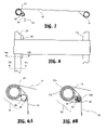
- FIG. 6A shows a side view of a lateral support member of the troop seats.
- FIG. 6B shows a top view of the lateral support member of the troop seats.
- FIG. 6C shows a top view of the lateral support member of the troop seats swung away to allow the troop seat to the collapsed.
- FIG. 7 is a side view of the high strength webbing attached to a rear longitudinal support and to a front longitudinal support including a tensioner.
- FIG. 8 is a top view of the high strength webbing attached to the rear longitudinal support and to the front longitudinal support including the tensioner.
- FIG. 9A is a cross-sectional view of the front longitudinal support and tensioner taken along line 9 A- 9 A of FIG. 8 .
- FIG. 9B is a cross-sectional view of the front longitudinal support and tensioner taken along line 9 B- 9 B of FIG. 8 .
- FIG. 10 is a cutaway view of internal hardware residing in the front longitudinal support.
- FIG. 11 is a perspective view of a female end of a first front longitudinal support of the one man troop seat.
- FIG. 11A is a cutaway perspective view of the female end of the first front longitudinal support of the one man troop seat.
- FIG. 11B is a side view of a mating receiver adapted to reside in the female end of the first front longitudinal support of the one man troop seat.
- FIG. 11C is an end view of the mating receiver adapted to reside in the female end of the first front longitudinal support of the one man troop seat.
- FIG. 12A is a cross-sectional view of the mating receiver taken long line 12 A- 12 A of FIG. 11B .
- FIG. 12B is a cross-sectional view of the mating receiver taken long line 12 B- 12 B of FIG. 12A .
- FIG. 12C is a cross-sectional view of the mating receiver in the unlatched position.
- FIG. 13 is a perspective view of an internal bolt residing in a male end of a second front longitudinal support.
- FIG. 13A is a cutaway perspective view of the internal bolt residing in the male end of the second front longitudinal support.
- FIG. 14 is a side view of the internal bolt extending from a bolt carrier.
- FIG. 14 A is a cross-sectional view of the internal bolt and bolt carrier taken along line 14 A- 14 A of FIG. 14 .
- FIG. 14 B is a cross-sectional view of the internal bolt and bolt carrier taken along line 14 B- 14 B of FIG. 14A with the internal bolt extending from the bolt carrier.
- FIG. 14C is a cross-sectional view of the internal bolt and bolt carrier taken along line 14 C- 14 C of FIG. 14A with the internal bolt retracted into the bolt carrier.
- FIG. 1 A three man troop seat 10 according to the present invention is shown in FIG. 1 .
- the troop seat 10 includes a seating area 16 comprising a lightweight seat fabric, a rear longitudinal support 22 attached to a bulkhead 14 , and a front longitudinal support 24 supported above a floor 12 by vertical supports 26 .
- An unused vertical support receiver 27 resides in the floor 12 .
- the three man troop seat 10 is shown in FIG. 2 with the light weight seat fabric cut away to show high strength webbing straps 18 used to reinforce the seating area 16 (see FIG. 1 ).
- Tensioner pulls 32 are provided for each webbing strap 18 to allow adjustment of the seating stretch to improve comfort and crash protection.
- Lateral supports 20 connect the rear longitudinal support 22 to the front longitudinal support 24 .
- the rear longitudinal support 22 is mechanically connected to the bulkhead 14 by bulkhead attachments 30 .
- the vertical supports 26 removably connect to vertical support receivers 27 using claws which grasp mating surfaces in the vertical support receivers 27 .
- the vertical supports include external sleeves which are actuated to retract the claws and allow the vertical supports 26 to be withdrawn from the vertical support receivers.
- Each of the two vertical supports 26 are braced by a diagonal support 28 .
- the diagonal supports 28 are pivotally mounted to the front longitudinal support 24 at pivots attached to the front longitudinal support 24 , and to the vertical supports 26 using quick release pins.
- a one man troop seat 10 a according to the present invention is shown attached to a two man troop seat 10 b according to the present invention in FIG. 3 .
- the one man troop seat 10 a has a first seating area 16 a and is supported by a single vertical support 26 .
- the two man troop seat 10 b has a second seating area 16 b and is supported by two vertical supports 26 .
- One of the two vertical supports 26 supporting the two man seat 10 b is braced by one diagonal support 28 .
- the one man troop seat 10 a and the attached two man troop seat 10 b with the light weight seat fabric cut away to show the high strength webbing straps 18 used to reinforce the light weight fabric are shown in FIG. 4 .
- the one man troop seat 10 a includes a first front longitudinal support 24 a and the two man troop seat 10 b includes a second front longitudinal support 24 b .
- the first front longitudinal support 24 a and the second front longitudinal support 24 b meet at separation 34 .
- the one man troop seat 10 a is shown alone (with the two man troop seat 10 b not shown) in FIG. 5A
- the two man troop seat 10 b is shown alone (with the one man troop seat 10 a not shown) in FIG. 5B .
- the one man troop seat 10 a and/or the two man troop seat 10 b may be collapsed or folded independently, thereby providing addition room for large equipment.
- FIG. 6A A side view of the lateral support member 20 of the troop seats 10 , 10 a , or 10 b is shown in FIG. 6A
- a top view of the lateral support member 20 is shown in FIG. 6B .
- the lateral support member 20 is connected to the rear longitudinal support 22 by a “C” shaped support end 20 b
- the longitudinal support member 20 is connected to the front longitudinal support 24 by a pivoting support end 20 a
- the lateral support member 20 pivots about a pin or screw 36 in the support end 20 a.
- FIG. 6C A top view of the lateral support member 20 swung away from the rear longitudinal support member 22 is shown in FIG. 6C .
- the lateral support member 20 pivots along an arc 37 about a pivot 36 in support end 20 a to allow the troop seat 10 , 10 a , or 10 b to the folded or collapsed.
- the pivot 36 preferably comprises a screw and nut.
- the support end 20 b preferably may be lifted to detach the lateral support member 20 from the rear longitudinal support member 22 .
- FIG. 7 A side view of the high strength webbing 18 attached to the rear longitudinal support 22 and to the front longitudinal support 24 is shown in FIG. 7 .
- the webbing straps 18 preferably wraps around the rear longitudinal support 22 and is sewn in place.
- FIG. 8 A top view of the high strength webbing 18 attached to the rear longitudinal support 22 and to the front longitudinal support 24 is shown in FIG. 8 .
- the webbing 18 is preferably a Kevlar® weave. Preferred widths are approximately 5.5 inches for the three man seat 10 , approximately five inches for the two man seat 10 b , and approximately four inches for the one man seat 10 a .
- a suitable webbing is part number MODIFIED 4856 available from Bally Ribbon Mills in Bally, Pa.
- a suitable seat back and/or bottom material is Conex® or Kevlar® fabric part number 3049B available from Sherman Textile Co. in Dallas, N.C.
- FIG. 9A A cross-sectional view a tensioner assembly 39 taken along line 9 A- 9 A of FIG. 8 are shown in FIG. 9A and a second cross-sectional view of the tensioner assembly 39 taken along line 9 B- 9 B of FIG. 8 is shown in FIG. 9B .
- the tensioner assembly 39 comprises strap take-up apparatus including a portion of the front longitudinal support 24 , a tensioner drum 38 , and a tensioner portion of the high strength webbing 18 .
- the tensioner portion of the high strength webbing 18 resides proximal to the front longitudinal support 24 and comprising an outer wrap 25 a , a drum wrap 25 b , an inner wrap 25 c , and the tensioner pull 32 .
- the outer wrap 25 a connecting to (or continues from) the seating portion of the high strength webbing 18 and wraps partially around the outside of the front longitudinal support 24 .
- the drum wrap 25 b connecting to (or continues from) the outer wrap 25 a and wraps partially around the tensioner drum 38 .
- the inner wrap 25 c connecting to (or continues from) the drum wrap 25 b and wraps partially around the front longitudinal support 24 residing between the front longitudinal support 24 and the outer wrap 25 a .
- the tensioner pull 32 connects to (or continues from) the inner wrap 25 c and falls over the tensioner drum 38 .
- the tensioner drum 38 is connected to the front longitudinal support by tensioner screws 40 , and tensioner springs 42 reside over the tensioner screws 40 to urge the tensioner drum 38 towards the front longitudinal support 24 .
- the tensioner assembly 39 is similar to known seat belt tensioners, wherein pulling in the tensioner pull 32 causes the high strength webbing 18 to advance through the tensioner assembly 39 , thereby tightening the seating area 16 (see FIGS. 1 and 3 ).
- the tensioners are a self-binding arrangement wherein the webbing is wrapped (or “looped”) around itself on the longitudinal support, thereby creating a binding (or locking) effect that increases with applied loads. The greater the applied load results in a greater binding effect.
- FIG. 10 A cutaway view of internal hardware 44 residing in the front longitudinal support 24 is shown in FIG. 10 .
- the internal hardware 44 provides the ability to attach various members such as the vertical supports 26 , the lateral supports 20 , the diagonal supports 28 (see FIGS. 2 and 4 ) and the like to the front longitudinal support 24 , or to any other tubular support.
- the internal hardware 44 is held in place by hardware screws 48 passing through a wall 49 of the front longitudinal support 24 and into the internal hardware 44 .
- An access passage 46 allows mounting screws to pass through the wall 49 and into the internal hardware to attach the various supports.
- the vertical supports 26 , the lateral supports 20 , and the diagonal supports 28 generally are attached using a bracket, for example, the pivoting support end 20 a in FIGS.
- the bracket is attached to the front longitudinal support 24 using the internal hardware.
- the diagonal supports 28 may also be attached to the vertical supports 26 using the internal hardware 44 residing in the vertical supports 26 .
- the internal hardware may thus be utilized for any connection of support elements of the troop seat 10 , 10 a , or 10 b in order to reduce protruding features, and any troop seat using internal hardware to reduce protruding features is intended to come within the scope of the present invention.
- FIG. 11 A perspective view of a female end of the first front longitudinal support 24 a (see FIG. 5A ) of the one man troop seat 10 a is shown in FIG. 11 .
- a hardware screw 48 passes through the wall 49 and into a mating receiver 50 residing inside the front longitudinal support 10 a .
- the mating receiver 50 has a mouth 56 and a latch 52 (see FIG. 12B ) which pivots about a latch pivot 54 , which latch 52 has a latch handle 53 .
- FIG. 11A A cutaway perspective view of the female end of the front longitudinal support 24 a of the one man troop seat 10 a is shown in FIG. 11A .
- the mating receiver 50 is substantially cylindrical and has a threaded hole 58 for the hardware screw 48 to threadedly cooperate with.
- FIG. 11B A side view of a mating receiver 50 is shown in FIG. 11B , and an end view of the mating receiver 50 is shown in FIG. 11C .
- a portion of the latch 52 is seen to intrude into the mouth 56 .
- FIG. 12A A cross-sectional view of the mating receiver 50 taken long line 12 A- 12 A of FIG. 11B is shown in FIG. 12A .
- the latch 52 pivots about the latch pivot 54 , and is biased in a latched position by a latch spring 60 .
- Two opposing threaded holes 58 allow attachment of the mating receiver 50 to the front longitudinal support 24 a.
- FIG. 12B A cross-sectional view of the mating receiver 50 taken long line 12 B- 12 B of FIG. 12A is shown in FIG. 12B with the latch 52 in a latched position
- a second cross-sectional view of the mating receiver 50 taken long line 12 B- 12 B of FIG. 12A is shown in FIG. 12C with the latch 52 in an unlatched position.
- the latch 52 is biased toward the latched position by the latch spring 60 , and actuation of the latch handle 53 along arc 55 moves the latch 55 to the unlatched position.
- FIG. 13 A perspective view of a male end of the second longitudinal support 24 b having an internal bolt 62 and bolt carrier 64 residing in a male end of a second front longitudinal support 24 b is shown in FIG. 13 .
- the hardware screw 48 holds the bolt carrier 64 in place.
- FIG. 13A A cutaway perspective view of the internal bolt 62 and bolt carrier 64 residing in the male end of the second front longitudinal support 24 b is shown in FIG. 13A .
- a bolt handle 66 is provided to move the internal bolt 62 axially within the bolt carrier 64 .
- FIG. 14 A side view of the internal bolt 62 extending from the bolt carrier 64 is shown in FIG. 14 .
- a cross-sectional view of the internal bolt 62 and bolt carrier 64 taken along line 14 A- 14 A of FIG. 14 is shown in FIG. 14A .
- Two opposing threaded holed 58 are provided to attach the bolt carrier 64 to the front longitudinal support 24 b.
- FIG. 14B A cross-sectional view of the internal bolt 62 and bolt carrier 64 taken along line 14 B- 14 B of FIG. 14A is shown in FIG. 14B , with the internal bolt 62 extending from the bolt carrier 64 , and a cross-sectional view of the internal bolt 62 and bolt carrier 64 taken along line 14 C- 14 C of FIG. 14A is shown in FIG. 14C with the internal bolt 62 retracted into the bolt carrier 64 .
- the bolt carrier 64 includes a passageway groove 78 , and a bolt clip 76 resides in the passageway groove 78 .
- the bolt clip 76 is a common retaining ring.
- the bolt 62 includes a latching feature comprising a bolt channel 68 for cooperation with the latch 52 (see FIGS. 12B and 12C ).
- the internal bolt 62 further includes a first bolt groove 70 and a second bolt groove 72 .
- the bolt clip 76 cooperates with the second bolt groove 72 to urge the internal bolt 62 to remain in the extended position.
- the bolt clip 76 cooperates with the second bolt groove 72 to urge the internal bolt 62 to remain in the retracted position.
Abstract
Description
Claims (18)
Priority Applications (1)
| Application Number | Priority Date | Filing Date | Title |
|---|---|---|---|
| US11/061,183 US7594701B2 (en) | 2005-02-18 | 2005-02-18 | Troop seat |
Applications Claiming Priority (1)
| Application Number | Priority Date | Filing Date | Title |
|---|---|---|---|
| US11/061,183 US7594701B2 (en) | 2005-02-18 | 2005-02-18 | Troop seat |
Publications (2)
| Publication Number | Publication Date |
|---|---|
| US20060186723A1 US20060186723A1 (en) | 2006-08-24 |
| US7594701B2 true US7594701B2 (en) | 2009-09-29 |
Family
ID=36911922
Family Applications (1)
| Application Number | Title | Priority Date | Filing Date |
|---|---|---|---|
| US11/061,183 Expired - Fee Related US7594701B2 (en) | 2005-02-18 | 2005-02-18 | Troop seat |
Country Status (1)
| Country | Link |
|---|---|
| US (1) | US7594701B2 (en) |
Cited By (13)
| Publication number | Priority date | Publication date | Assignee | Title |
|---|---|---|---|---|
| US20080173761A1 (en) * | 2007-01-22 | 2008-07-24 | Herrmann Benthien | Fitting for introducing high forces into a fuselage cell of an aircraft |
| US20080191530A1 (en) * | 2006-07-21 | 2008-08-14 | Basham Christina L | Special expandable booster bench |
| US20080231068A1 (en) * | 2007-03-21 | 2008-09-25 | Plasan Sasa Ltd. | Method and suspension apparatus for suspending an object in a vehicle |
| US20100109400A1 (en) * | 2008-10-31 | 2010-05-06 | Kneller Heidi J | Adjustable width seats |
| US20100219291A1 (en) * | 2007-06-15 | 2010-09-02 | Airbus Operations | Aircraft hold intended to accommodate baggage |
| US20110109126A1 (en) * | 2009-11-12 | 2011-05-12 | Bonnie Breit | Foldable Seating Apparatus |
| US20110156448A1 (en) * | 2009-12-26 | 2011-06-30 | Stephen Fletcher | Portable Chair, Table And Umbrella Stand |
| RU2462378C1 (en) * | 2011-04-13 | 2012-09-27 | Открытое акционерное общество "Тверской вагоностроительный завод" (ОАО "ТВЗ") | Berth in passenger car |
| US20140008950A1 (en) * | 2011-02-05 | 2014-01-09 | Sitech Sitztechnik Gmbh | Variable lightweight seat concept |
| CN104757806A (en) * | 2015-04-10 | 2015-07-08 | 姚水福 | Wall-hanging turning power-assisted stool with automatic reset function |
| EP3000732A1 (en) | 2014-09-23 | 2016-03-30 | Airbus Helicopters | An aircraft bench organized to receive a variable number of passengers |
| US20190290017A1 (en) * | 2016-10-26 | 2019-09-26 | Ashley Furniture Industries, Inc. | Textile deck assembly for furniture items |
| US10913537B2 (en) * | 2017-03-29 | 2021-02-09 | Airbus Interiors Services | Retractable chair for an aircraft cabin |
Families Citing this family (5)
| Publication number | Priority date | Publication date | Assignee | Title |
|---|---|---|---|---|
| FR2973336A1 (en) * | 2011-03-30 | 2012-10-05 | Expliseat Sas | AIRCRAFT SEAT WITH FLEXIBLE FEATURE |
| CA2838510A1 (en) * | 2011-06-07 | 2012-12-13 | Tamarack Habilitation Technologies, Inc. | Apparatus and method for automatic adjustment of a support surface with interwoven support elements |
| KR101349302B1 (en) | 2012-03-22 | 2014-01-10 | 장호일 | folding leg of chair on the wall |
| EP2939920B1 (en) | 2014-04-29 | 2021-10-13 | Airbus Operations GmbH | Deployable floor panel arrangement for aircraft cabin area |
| CN104494482B (en) * | 2014-11-21 | 2016-07-13 | 重庆市华青汽车配件有限公司 | There is the automobile rear seat of multiple use state |
Citations (24)
| Publication number | Priority date | Publication date | Assignee | Title |
|---|---|---|---|---|
| US2556076A (en) | 1944-09-15 | 1951-06-05 | Robert B Evans | Troopship type airplane seat structure |
| US2556077A (en) * | 1950-11-27 | 1951-06-05 | Evans Prod Co | Combination seat and bed |
| US2557817A (en) | 1948-09-30 | 1951-06-19 | Rca Corp | Alternating current frequency measuring |
| US2638151A (en) * | 1950-04-17 | 1953-05-12 | Jones Gordon Karl | Seat for vehicles such as aircraft |
| US2685912A (en) | 1951-06-20 | 1954-08-10 | Evans Prod Co | Troopship type airplane seat structure |
| US2700412A (en) | 1944-09-15 | 1955-01-25 | Evans Prod Co | Troopship type airplane seat structure |
| US2971566A (en) | 1958-01-27 | 1961-02-14 | Sud Aviation | Pilot seats for aircraft, more particularly for helicopter |
| US3057613A (en) * | 1959-04-08 | 1962-10-09 | Benjamin Cyril Moss | Spring assemblies for seats, settees, beds and the like |
| US3314720A (en) | 1965-02-11 | 1967-04-18 | Millington Ralph | Safety troop seat |
| US3316013A (en) * | 1965-08-13 | 1967-04-25 | Daniels C R Inc | Folding seat construction |
| US3785600A (en) * | 1972-01-25 | 1974-01-15 | 1P Ind Chimica Arredamento S P | Adjustable mounting assemblies for groups of seats in aircraft or other vehicles |
| US4437629A (en) * | 1982-08-09 | 1984-03-20 | The Boeing Company | Seat structure having an adjustable seat back and support shelf especially for accommodating parachute packs |
| US4514107A (en) * | 1983-05-25 | 1985-04-30 | Moreno Gil G | Device for joining tubular members |
| US4740030A (en) * | 1984-07-12 | 1988-04-26 | Nordskog Robert A | Jump seat assembly and seat with improved safety belt array |
| US4858992A (en) * | 1985-10-07 | 1989-08-22 | Lasota Larry | Conformable seat |
| US4994317A (en) * | 1988-12-21 | 1991-02-19 | Springs Industries, Inc. | Flame durable fire barrier fabric |
| US5533788A (en) * | 1990-05-31 | 1996-07-09 | Galsten Trading, Inc. | Ready-to-assemble furniture with improved fastening means |
| US5553923A (en) * | 1993-12-08 | 1996-09-10 | Weber Aircraft, Inc. | Base frame for an aircraft seat |
| US5769360A (en) * | 1995-03-27 | 1998-06-23 | Research Foundation Of The State University Of New York | Easy transport seat |
| US6152401A (en) * | 1997-12-23 | 2000-11-28 | Air Methods Corporation | Deployable chair system for use in patient transport aircraft |
| US6394393B1 (en) * | 2000-08-25 | 2002-05-28 | Skyline Industries, Inc. | Crashworthy aircraft seat |
| US20030071510A1 (en) * | 2001-09-13 | 2003-04-17 | Martin Mezger | Seat with flexible rubber panel |
| US6925945B2 (en) * | 2002-06-07 | 2005-08-09 | Jsj Furniture Corporation | Leg attachment and method for manufacturing same |
| US20060237586A1 (en) * | 2005-04-21 | 2006-10-26 | The Boeing Company | Adjustable attenuation system for a space re-entry vehicle seat |
-
2005
- 2005-02-18 US US11/061,183 patent/US7594701B2/en not_active Expired - Fee Related
Patent Citations (25)
| Publication number | Priority date | Publication date | Assignee | Title |
|---|---|---|---|---|
| US2556076A (en) | 1944-09-15 | 1951-06-05 | Robert B Evans | Troopship type airplane seat structure |
| US2700412A (en) | 1944-09-15 | 1955-01-25 | Evans Prod Co | Troopship type airplane seat structure |
| US2557817A (en) | 1948-09-30 | 1951-06-19 | Rca Corp | Alternating current frequency measuring |
| US2638151A (en) * | 1950-04-17 | 1953-05-12 | Jones Gordon Karl | Seat for vehicles such as aircraft |
| US2556077A (en) * | 1950-11-27 | 1951-06-05 | Evans Prod Co | Combination seat and bed |
| US2685912A (en) | 1951-06-20 | 1954-08-10 | Evans Prod Co | Troopship type airplane seat structure |
| US2971566A (en) | 1958-01-27 | 1961-02-14 | Sud Aviation | Pilot seats for aircraft, more particularly for helicopter |
| US3057613A (en) * | 1959-04-08 | 1962-10-09 | Benjamin Cyril Moss | Spring assemblies for seats, settees, beds and the like |
| US3314720A (en) | 1965-02-11 | 1967-04-18 | Millington Ralph | Safety troop seat |
| US3316013A (en) * | 1965-08-13 | 1967-04-25 | Daniels C R Inc | Folding seat construction |
| US3785600A (en) * | 1972-01-25 | 1974-01-15 | 1P Ind Chimica Arredamento S P | Adjustable mounting assemblies for groups of seats in aircraft or other vehicles |
| US4437629A (en) * | 1982-08-09 | 1984-03-20 | The Boeing Company | Seat structure having an adjustable seat back and support shelf especially for accommodating parachute packs |
| US4514107A (en) * | 1983-05-25 | 1985-04-30 | Moreno Gil G | Device for joining tubular members |
| US4740030A (en) * | 1984-07-12 | 1988-04-26 | Nordskog Robert A | Jump seat assembly and seat with improved safety belt array |
| US4858992A (en) * | 1985-10-07 | 1989-08-22 | Lasota Larry | Conformable seat |
| US4994317A (en) * | 1988-12-21 | 1991-02-19 | Springs Industries, Inc. | Flame durable fire barrier fabric |
| US5533788A (en) * | 1990-05-31 | 1996-07-09 | Galsten Trading, Inc. | Ready-to-assemble furniture with improved fastening means |
| US5553923A (en) * | 1993-12-08 | 1996-09-10 | Weber Aircraft, Inc. | Base frame for an aircraft seat |
| US5769360A (en) * | 1995-03-27 | 1998-06-23 | Research Foundation Of The State University Of New York | Easy transport seat |
| US6152401A (en) * | 1997-12-23 | 2000-11-28 | Air Methods Corporation | Deployable chair system for use in patient transport aircraft |
| US6394393B1 (en) * | 2000-08-25 | 2002-05-28 | Skyline Industries, Inc. | Crashworthy aircraft seat |
| US6585190B2 (en) * | 2000-08-25 | 2003-07-01 | Skyline Industries, Inc. | Crashworthy aircraft seat |
| US20030071510A1 (en) * | 2001-09-13 | 2003-04-17 | Martin Mezger | Seat with flexible rubber panel |
| US6925945B2 (en) * | 2002-06-07 | 2005-08-09 | Jsj Furniture Corporation | Leg attachment and method for manufacturing same |
| US20060237586A1 (en) * | 2005-04-21 | 2006-10-26 | The Boeing Company | Adjustable attenuation system for a space re-entry vehicle seat |
Cited By (33)
| Publication number | Priority date | Publication date | Assignee | Title |
|---|---|---|---|---|
| US20080191530A1 (en) * | 2006-07-21 | 2008-08-14 | Basham Christina L | Special expandable booster bench |
| US7895810B2 (en) | 2007-01-22 | 2011-03-01 | Airbus Deutschland Gmbh | Crash paddle for reinforcing a primary fuselage structure of an aircraft |
| US20080173755A1 (en) * | 2007-01-22 | 2008-07-24 | Herrmann Benthien | Floor panel for forming a loading area in a cargo hold of an aircraft |
| US20080173758A1 (en) * | 2007-01-22 | 2008-07-24 | Herrmann Benthien | Crash paddle for reinforcing a primary fuselage structure of an aircraft |
| US20080173756A1 (en) * | 2007-01-22 | 2008-07-24 | Herrmann Benthien | Lining framework for an aircraft |
| US8408492B2 (en) | 2007-01-22 | 2013-04-02 | Airbus Deutschland Gmbh | Floor panel for forming a loading area in a cargo hold of an aircraft |
| US8382038B2 (en) | 2007-01-22 | 2013-02-26 | Airbus Operations Gmbh | Device, in particular connection rod, for bracing a fuselage structure of an aircraft and/or for fastening a component |
| US8220744B2 (en) | 2007-01-22 | 2012-07-17 | Airbus Deutschland Gmbh | Fitting for introducing high forces into a fuselage cell of an aircraft |
| US7775479B2 (en) * | 2007-01-22 | 2010-08-17 | Airbus Deutschland Gmbh | Lining framework for an aircraft |
| US20080173761A1 (en) * | 2007-01-22 | 2008-07-24 | Herrmann Benthien | Fitting for introducing high forces into a fuselage cell of an aircraft |
| US20110108668A1 (en) * | 2007-01-22 | 2011-05-12 | Hermann Benthien | Device, in particular connection rod, for bracing a fuselage structure of an aircraft and/or for fastening a component |
| US8091944B2 (en) * | 2007-03-21 | 2012-01-10 | Plasan Sasa Ltd. | Suspension apparatus for suspending an object in a vehicle |
| US20100253109A1 (en) * | 2007-03-21 | 2010-10-07 | Plasan Sasa Ltd. | Method and suspension apparatus for suspending an object in a vehicle |
| US20080231068A1 (en) * | 2007-03-21 | 2008-09-25 | Plasan Sasa Ltd. | Method and suspension apparatus for suspending an object in a vehicle |
| US7758095B2 (en) * | 2007-03-21 | 2010-07-20 | Plasan Sasa Ltd. | Method and suspension apparatus for suspending an object in a vehicle |
| US20100219291A1 (en) * | 2007-06-15 | 2010-09-02 | Airbus Operations | Aircraft hold intended to accommodate baggage |
| US8152103B2 (en) * | 2007-06-15 | 2012-04-10 | Airbus Operations Sas | Aircraft hold with deployable bench to accommodate baggage stowage |
| US20100109400A1 (en) * | 2008-10-31 | 2010-05-06 | Kneller Heidi J | Adjustable width seats |
| US8028958B2 (en) * | 2008-10-31 | 2011-10-04 | The Boeing Company | Adjustable width seats |
| US8550546B2 (en) * | 2009-11-12 | 2013-10-08 | Bonnie Breit | Foldable seating apparatus |
| US20110109126A1 (en) * | 2009-11-12 | 2011-05-12 | Bonnie Breit | Foldable Seating Apparatus |
| US20110156448A1 (en) * | 2009-12-26 | 2011-06-30 | Stephen Fletcher | Portable Chair, Table And Umbrella Stand |
| US20140008950A1 (en) * | 2011-02-05 | 2014-01-09 | Sitech Sitztechnik Gmbh | Variable lightweight seat concept |
| US8919854B2 (en) * | 2011-02-05 | 2014-12-30 | Volkswagen Aktiengesellschaft | Variable lightweight seat concept |
| RU2462378C1 (en) * | 2011-04-13 | 2012-09-27 | Открытое акционерное общество "Тверской вагоностроительный завод" (ОАО "ТВЗ") | Berth in passenger car |
| EP3000732A1 (en) | 2014-09-23 | 2016-03-30 | Airbus Helicopters | An aircraft bench organized to receive a variable number of passengers |
| US9963235B2 (en) | 2014-09-23 | 2018-05-08 | Airbus Helicopters | Aircraft bench organized to receive a variable number of passengers |
| CN104757806A (en) * | 2015-04-10 | 2015-07-08 | 姚水福 | Wall-hanging turning power-assisted stool with automatic reset function |
| US20190290017A1 (en) * | 2016-10-26 | 2019-09-26 | Ashley Furniture Industries, Inc. | Textile deck assembly for furniture items |
| US10980354B2 (en) * | 2016-10-26 | 2021-04-20 | Ashley Furniture Industries, Inc. | Textile deck assembly for furniture items |
| US11523690B2 (en) * | 2016-10-26 | 2022-12-13 | Ashley Furniture Industries, Inc. | Textile deck assembly for furniture items |
| US11844431B2 (en) | 2016-10-26 | 2023-12-19 | Ashley Furniture Industries, Inc | Textile deck assembly for furniture items |
| US10913537B2 (en) * | 2017-03-29 | 2021-02-09 | Airbus Interiors Services | Retractable chair for an aircraft cabin |
Also Published As
| Publication number | Publication date |
|---|---|
| US20060186723A1 (en) | 2006-08-24 |
Similar Documents
| Publication | Publication Date | Title |
|---|---|---|
| US7594701B2 (en) | Troop seat | |
| US8123279B2 (en) | Net structures, vehicles including net structures, and methods | |
| US10414503B2 (en) | Components for enhancement of a low profile crew attendant seat | |
| US6073986A (en) | Easily handled movable vehicle seat assembly | |
| US7090168B1 (en) | Catenary girt arrangement for emergency evacuation slides | |
| AU2012282886B2 (en) | Restraint system with dual release mechanisms | |
| US20140209741A1 (en) | Aircraft monument comprising an integrated cabin attendant seat and aircraft area | |
| US8840163B1 (en) | Energy attenutating seat and litter support | |
| US10189573B2 (en) | Off-wing slide raft | |
| US6053555A (en) | Removable seat assembly | |
| US20090045652A1 (en) | Cargo net | |
| JPH1191697A (en) | Expansible emergency slide assembly | |
| US8794709B2 (en) | Child restraint devices for use with seats | |
| DE102014203671A1 (en) | Luggage restraint system | |
| US11708167B2 (en) | Multipurpose readiness indicator for off-wing slide raft | |
| DE102014203670A1 (en) | LUGGAGE RESTRAINT SYSTEM | |
| US4938436A (en) | Safety harness and belt assemblies for aircraft crewmembers | |
| US20130169020A1 (en) | Ergonomic seat arrangement for military and other vehicles | |
| US8708284B2 (en) | Adjustable parachute cargo harness | |
| CN110371302B (en) | Umbrella bag strap system with one-key unlocking device | |
| RU164559U1 (en) | FREIGHT NETWORK FOR HELICOPTER LUGGAGE | |
| US11247081B2 (en) | Method of rescuing a subject positioned in a vehicle and a rescue device | |
| US11260980B2 (en) | Buckle-up aid for parachutist | |
| US20110084163A1 (en) | Aircraft gear caddy | |
| US20240124143A1 (en) | Vehicular seat assembly having expandable seat back section |
Legal Events
| Date | Code | Title | Description |
|---|---|---|---|
| AS | Assignment |
Owner name: H. KOCH & SONS CO., CALIFORNIA Free format text: ASSIGNMENT OF ASSIGNORS INTEREST;ASSIGNORS:KAWABATA, ERIC;DRUFF, CHARLIE BAN;DURAN, MICHAEL;REEL/FRAME:016304/0793 Effective date: 20050216 |
|
| AS | Assignment |
Owner name: STARTRAK SYSTEMS LLC, NEW JERSEY Free format text: ASSIGNMENT OF ASSIGNORS INTEREST;ASSIGNORS:KARUPPANAN, VENKATESWARAN;PERTEN, HERBERT;ROBINSON, THOMAS A.;AND OTHERS;REEL/FRAME:019352/0885 Effective date: 20070525 |
|
| AS | Assignment |
Owner name: CONAX FLORIDA CORPORATION, FLORIDA Free format text: ASSIGNMENT OF ASSIGNORS INTEREST;ASSIGNOR:H. KOCH & SONS CO.;REEL/FRAME:021049/0445 Effective date: 20080330 |
|
| FEPP | Fee payment procedure |
Free format text: PAYOR NUMBER ASSIGNED (ORIGINAL EVENT CODE: ASPN); ENTITY STATUS OF PATENT OWNER: LARGE ENTITY |
|
| FPAY | Fee payment |
Year of fee payment: 4 |
|
| AS | Assignment |
Owner name: CARLETON LIFE SUPPORT SYSTEMS INC., IOWA Free format text: ASSIGNMENT OF ASSIGNORS INTEREST;ASSIGNOR:CONAX FLORIDA CORPORATION;REEL/FRAME:031647/0265 Effective date: 20130903 |
|
| REMI | Maintenance fee reminder mailed | ||
| LAPS | Lapse for failure to pay maintenance fees |
Free format text: PATENT EXPIRED FOR FAILURE TO PAY MAINTENANCE FEES (ORIGINAL EVENT CODE: EXP.) |
|
| STCH | Information on status: patent discontinuation |
Free format text: PATENT EXPIRED DUE TO NONPAYMENT OF MAINTENANCE FEES UNDER 37 CFR 1.362 |
|
| FP | Lapsed due to failure to pay maintenance fee |
Effective date: 20170929 |