EP3160802B1 - Motor vehicle seat comprising a strap guide for a safety belt - Google Patents
Motor vehicle seat comprising a strap guide for a safety belt Download PDFInfo
- Publication number
- EP3160802B1 EP3160802B1 EP15742357.5A EP15742357A EP3160802B1 EP 3160802 B1 EP3160802 B1 EP 3160802B1 EP 15742357 A EP15742357 A EP 15742357A EP 3160802 B1 EP3160802 B1 EP 3160802B1
- Authority
- EP
- European Patent Office
- Prior art keywords
- seat
- backrest
- motor vehicle
- belts
- bench
- Prior art date
- Legal status (The legal status is an assumption and is not a legal conclusion. Google has not performed a legal analysis and makes no representation as to the accuracy of the status listed.)
- Active
Links
- 210000002105 tongue Anatomy 0.000 claims description 5
- 238000003780 insertion Methods 0.000 claims description 3
- 230000037431 insertion Effects 0.000 claims description 3
- 239000002184 metal Substances 0.000 description 9
- 210000004197 pelvis Anatomy 0.000 description 4
- 238000004873 anchoring Methods 0.000 description 2
- 238000012423 maintenance Methods 0.000 description 2
- 230000035939 shock Effects 0.000 description 2
- 208000031968 Cadaver Diseases 0.000 description 1
- 241001080024 Telles Species 0.000 description 1
- 239000000463 material Substances 0.000 description 1
- 230000001105 regulatory effect Effects 0.000 description 1
Images

Classifications
-
- B—PERFORMING OPERATIONS; TRANSPORTING
- B60—VEHICLES IN GENERAL
- B60R—VEHICLES, VEHICLE FITTINGS, OR VEHICLE PARTS, NOT OTHERWISE PROVIDED FOR
- B60R22/00—Safety belts or body harnesses in vehicles
- B60R22/18—Anchoring devices
-
- B—PERFORMING OPERATIONS; TRANSPORTING
- B60—VEHICLES IN GENERAL
- B60N—SEATS SPECIALLY ADAPTED FOR VEHICLES; VEHICLE PASSENGER ACCOMMODATION NOT OTHERWISE PROVIDED FOR
- B60N2/00—Seats specially adapted for vehicles; Arrangement or mounting of seats in vehicles
- B60N2/68—Seat frames
- B60N2/688—Particular seat belt attachment and guiding
-
- B—PERFORMING OPERATIONS; TRANSPORTING
- B60—VEHICLES IN GENERAL
- B60R—VEHICLES, VEHICLE FITTINGS, OR VEHICLE PARTS, NOT OTHERWISE PROVIDED FOR
- B60R22/00—Safety belts or body harnesses in vehicles
- B60R22/18—Anchoring devices
- B60R22/26—Anchoring devices secured to the seat
-
- B—PERFORMING OPERATIONS; TRANSPORTING
- B60—VEHICLES IN GENERAL
- B60R—VEHICLES, VEHICLE FITTINGS, OR VEHICLE PARTS, NOT OTHERWISE PROVIDED FOR
- B60R22/00—Safety belts or body harnesses in vehicles
- B60R22/18—Anchoring devices
- B60R2022/1818—Belt guides
-
- B—PERFORMING OPERATIONS; TRANSPORTING
- B60—VEHICLES IN GENERAL
- B60R—VEHICLES, VEHICLE FITTINGS, OR VEHICLE PARTS, NOT OTHERWISE PROVIDED FOR
- B60R22/00—Safety belts or body harnesses in vehicles
- B60R22/18—Anchoring devices
- B60R22/20—Anchoring devices adjustable in position, e.g. in height
- B60R2022/207—Horizontally or transversally adjustable
-
- B—PERFORMING OPERATIONS; TRANSPORTING
- B60—VEHICLES IN GENERAL
- B60R—VEHICLES, VEHICLE FITTINGS, OR VEHICLE PARTS, NOT OTHERWISE PROVIDED FOR
- B60R22/00—Safety belts or body harnesses in vehicles
- B60R22/18—Anchoring devices
- B60R22/26—Anchoring devices secured to the seat
- B60R2022/266—Rear seats, e.g. benches
Definitions
- the present invention relates generally to the safety of passengers in a motor vehicle.
- a motor vehicle seat comprising a seat and a backrest which has a bottom edge facing the seat, an opposite upper edge, and two side edges.
- It also relates to a motor vehicle comprising a frame, a bench as mentioned above, and two central seatbelts each comprising a strap.
- a motor vehicle has two or three rows of seats.
- the second row of seats is designed to accommodate a variable number of passengers, depending on the type of vehicle.
- the seat belts of the two side seats are of the "three-point attachment" type, in that the strap of each seat belt is attached to a first point on one side of the passenger's pelvis. , pass in front of the passenger's pelvis to a second point, then back across the passenger's chest to a third point above the first point.
- Such a seat belt ensures a good support of the passenger in case of shock.
- the seat-belt of the seat of the seat is of the "two point-of-attachment" type, in that the strap of the seat belt is attached to a first point on one side of the pelvis, and it simply passes over. in front of the passenger's pelvis to a second point of attachment.
- Such a seat belt ensures a less effective maintenance of the passenger in case of impact.
- the present invention proposes replacing the two-point seat belts with three-point seat belts, while complying with the regulatory standards in force. .
- a seat as defined in the introduction which comprises a strap guide for seat belt webbing, which is mounted movable on the backrest, away from the side edges of this folder, so as to have an adjustable height relative to the upper edge of the folder, and which comprises a body defining two separate passages for two belts of seat belts and wherein the two passages are superimposed.
- this strap guide constitutes a third point of attachment for the seat belt strap (s) assigned to the passenger (s) sitting in the center of the seat, in that it will allow to guide each strap from a strap retractor to above the shoulder of this (s) passenger (s).
- the mobile assembly height of the strap guide relative to the backrest will allow him to adjust the height of the third fixing point depending on the size of the passenger. In this way, the seatbelt webbing will be properly adjusted to the passenger's torso so that in the event of a crash, it will not hurt the passenger.
- this strap guide By placing itself in the event that the seat is likely to accommodate up to four passengers, this strap guide will be located substantially equidistant from the lateral edges of the backrest.
- the invention also relates to a motor vehicle as defined in the introduction, in which there is provided a bench as defined previously, which is mounted on the frame and the strap guide allows the passage of the two belts central safety belts.
- a motor vehicle 1 comprises a chassis 2 which notably comprises a floor, two lateral wings and a roof (see Figures 4 to 6 ).
- This motor vehicle 1 here comprises two front seats and a rear seat 10 shown on the figure 1 .
- front and rear will be used with respect to this motor vehicle, the front of a component of the motor vehicle designating the side of this component which is turned towards the hood of the vehicle and the rear designating the side of this component which is turned towards the trunk.
- the motor vehicle is of the "tri-body" type.
- a motor vehicle comprises a trunk, a passenger compartment and a hood which, seen from the side, form two unhooked, one at the bottom of the windshield and the other at the bottom of the rear window.
- the chassis comprises a metal shelf which extends between the two side wings, at the rear of the seat 10, at the junction between the rear window and the trunk.
- the seat 10 has a seat 20 and a backrest 30. It is here provided to accommodate up to four passengers.
- the seat 20 and the backrest 30 each comprise a metal frame (not visible in the figures) covered with a pad for the comfort of passengers.
- the seat 20 is directly mounted on the floor of the motor vehicle. It is preferably mounted fixedly, by means of feet which, on one side, are welded to the frame of the seat, and which, on the other side, are screwed on the floor.
- the backrest could be fixed to the seat or the chassis of the vehicle.
- the backrest 30 is rather movably mounted on the seat 20, by means of a hinge allowing it to tilt forward.
- the backrest 30 is thus movable between a position of use in which it extends vertically so that a passenger can sit on the seat 10, and a folded position in which it extends horizontally against the seat to free up cargo space in the trunk of the motor vehicle.
- the seat 20 and the backrest 30 are monoblock, in that they each comprise a rigid metal frame.
- the folder 30 as the seat 20 are not breakable: they are not here provided to be partially folded.
- This backrest 30 has a lower edge 31 which, in the position of use, is turned towards the seat 20. It also has an opposite upper edge 32 (turned towards the roof of the motor vehicle), and two lateral edges (respectively turned towards the side wings of the motor vehicle).
- the seat 10 has exactly two headrests 40 which are fixed to the upper edge 32 of the backrest 30.
- each headrest 40 has a width such that when the seat 10 accommodates four passengers 300, 400, it extends to the rear of the heads of two of the passengers 300, 400.
- these headrests 40 each comprise a metal frame covered with a lining, and two parallel rods 41 which are welded to the frame of the headrest 40 and which are slidably mounted in two sockets fixed to the metal frame of the backrest 30 (see figure 1 ). In this way, the two headrests 40 are movable relative to the backrest 30, between a high position and a low position (bearing against the backrest 30).
- Each of the two aforementioned sleeves comprises a sheath which is welded to the metal frame of the backrest 30 and which lodges a plastic sheath internally.
- This sheath has at its upper end a flange that emerges outside the backrest to define a passage for one of the parallel rods 41 of the headrest 40.
- the sheath is used to guide the sliding of this Parallel rod 41.
- This sheath also comprises locking tabs which are adapted to cooperate with notches provided on parallel rods 41 to lock the headrest 40 upwardly.
- the motor vehicle is also equipped with four seat belts 50, 60, 70, 80 for the four passengers.
- Each seat belt 50, 60, 70, 80 is here of the type with three attachment points.
- Each belt then comprises a retractor 52, 62, 72, 82 fixed to a structural part of the motor vehicle, a strap 51, 61, 71, 81 a part of which is wound in the reel and another part emerges from the reel, and a bolt 53, 63, 73, 83.
- the reels 72, 82 of the two outer seat belts 70, 80 are directly attached to the lateral wings of the motor vehicle, here by screwing.
- the strap 71, 81 of each of these two outer seat belts 70, 80 emerges from the reel 72, 82, passes through a guide 74, 84 which is fixed to one of the lateral wings of the motor vehicle (at upper edge of the backrest 30), then down to the floor where its free end is fixed.
- the reels 52, 62 of the two central safety belts 50, 60 are fixed to the rear shelf (not shown) of the frame, for example by screwing.
- each of these two central seat belts 50, 60 emerges from the reel, passes through a strap guide 100 located between the two headrests 40, then back down to the floor where its free end is fixed .
- Each strap 51, 61 passes either through a passage provided in the seat 20, or between the seat 20 and the backrest 30.
- the present invention thus relates more precisely to the webbing guide 100.
- this strap guide 100 is mounted movably on the backrest 30, away from the lateral edges 33 of the backrest 30, so as to have a height h adjustable relative to the upper edge 32 of the backrest 30 (see FIG. figure 2 ).
- the strap guide 100 comprises mounting means 110 on the backrest 30, and a body 120.
- the strap guide 100 is located at equal distances from the lateral edges of the backrest 30. According to the invention it delimits two passages 125, 126 separate for the two straps 51, 61 of the central safety belts 50, 60.
- the body 120 is in the form of a rectangular plate
- the mounting means 110 are in the form of two rods 111 which extend from the lower edge of the body 120, perpendicular thereto.
- the body 120 and the two rods 111 are either formed in one piece, by stamping a metal plate, or assembled to form a single piece. It may be provided to cover the body 120 with a plastic skin, for example by overmolding the metal plate.
- the two rods 111 are here identical to those fitted to the headrests 40. They are then slidably mounted in plastic sheaths housed in two sockets welded to the metal frame of the backrest 30. These bushings and these sheaths are again identical here. to those accommodating the rods 41 of the headrests 40.
- webbing guide 100 can thus be mounted in place of a central headrest of a bench originally intended to accommodate three passengers only.
- the body 120 is movable relative to the backrest 30, between a high position and a low position (bearing against the backrest 30).
- the snap-fastening tongues provided on the sheaths made of pastic material are then provided to cooperate with notches provided on the stems 111 of the strap guide 100, which allows the passengers to manually adjust the height h of this strap guide 100 with respect to the upper edge 32 of the backrest 30.
- the two passages 125, 126 delimited by the body 120 are superimposed in height (one above the other).
- each of these two passages 125, 126 is in the form of a slot, a first portion 125A, 126A is slightly curved, and a second portion 125B, 126B is curved in a semicircle.
- These two passages 125, 126 are positioned head-to-tail on top of each other, so that the first portions 125A, 126A of these passages 125, 126 are inclined relative to one another, V.
- Each passage 125, 126 here has an open contour. More specifically, each passageway 125, 126 communicates with the outside of the strap guide 100, via an engagement slot 127, 128 which extends from the edge of the body 120 to the corresponding passage 125, 126.
- This engagement slot 127, 128 makes it easy to insert or extract a seat belt strap in the passage 125, 126 corresponding.
- the bolts 53, 63, 73, 83 of the safety belts 50, 60, 70, 80 are designed to be engaged and locked in anchoring means 91, 92, 93, 94, 95, 96 provided at the level of the seat 20 of the bench 10.
- each bolt comprises, on the one hand, a body that has a slot slipped on the strap, and, on the other hand, a plate that extends from the body and is intended to lock in a peduncle.
- each anchoring means is formed by a peduncle mounted on a support.
- more peduncles 91, 92, 93, 94, 95, 96 are provided than bolts mounted on the seat belts 50, 60, 70, 80.
- the motor vehicle comprises, for the seat 10, six pedicles 91, 92, 93, 94, 95, 96 and only four seat belts 50, 60, 70, 80 each equipped with a single bolt.
- peduncles 93, 94, 95, 96 central, which are distributed in pairs along the seat 20, between the two peduncles 91, 92 outside, at a distance thereof.
- the two peduncles of each pair of peduncles 93, 94, 95, 96 are here fixed on the same support.
- the two supports are here provided so that the four pedicels are retractable relative to the seat 20. In this way, when they are not used, these peduncles can be placed in such a way that a passenger can sit on it without being embarrassed.
- these supports are for this purpose formed by straps (not visible) connected to the floor of the motor vehicle.
- the four peduncles are in turn provided to retract either in cavities dug in the seat 20 (see figure 1 ), or at the junction between the seat 20 and the backrest 30.
- the two passengers 200 can (before sitting down) tilt the backrest 30 forward so as to pass the straps 71, 81 of these two seat belts 70, 80 at the rear of the backrest 30, before bringing the backrest to the use position. Hooks provided for this purpose at the back of the backrest 30 can facilitate the maintenance of the straps 71, 81 at the rear of the seat 10.
- the two passengers 200 can also adjust the height of the strap guide 100, moving it here in the high position.
- the two passengers 400 sitting in the center of the seat 10 can adjust the height of the strap guide 100, by moving it here in low position.
- the passenger 200 of larger body builds uses the seat belt 50 which emerges from the passage 125 the highest of the strap guide 100 , while the other passenger uses the seat belt 60 which emerges from the lowest passage 126 of the strap guide 100.
- the advantage of having two passages 125, 126 superimposed is thus to allow each passenger to use a seat belt whose strap is correctly positioned in height relative to his shoulder.
Description
La présente invention concerne de manière générale la sécurité des passagers dans un véhicule automobile.The present invention relates generally to the safety of passengers in a motor vehicle.
Elle concerne plus particulièrement une banquette de véhicule automobile, comprenant une assise et un dossier qui présente un bord inférieur tourné vers l'assise, un bord supérieur opposé, et deux bords latéraux.It relates more particularly to a motor vehicle seat, comprising a seat and a backrest which has a bottom edge facing the seat, an opposite upper edge, and two side edges.
Elle concerne aussi un véhicule automobile comportant un châssis, une banquette telle que précitée, et deux ceintures de sécurité centrales comportant chacune une sangle.It also relates to a motor vehicle comprising a frame, a bench as mentioned above, and two central seatbelts each comprising a strap.
Généralement, un véhicule automobile comporte deux ou trois rangées de sièges.Generally, a motor vehicle has two or three rows of seats.
La seconde rangée de sièges est conçue pour accueillir un nombre variable de passagers, selon le type du véhicule.The second row of seats is designed to accommodate a variable number of passengers, depending on the type of vehicle.
On connaît ainsi des banquettes pouvant recevoir jusqu'à trois passagers. Une telle banquette délimite alors un siège central et deux sièges latéraux situés de part et d'autre de ce siège central.We thus know benches that can accommodate up to three passengers. Such a bench then delimits a central seat and two side seats located on either side of this central seat.
Dans ce genre de banquettes, les ceintures de sécurité des deux sièges latéraux sont du type « à trois points de fixation », en ce sens que la sangle de chaque ceinture de sécurité est fixée à un premier point d'un côté du bassin du passager, passe devant le bassin du passager jusqu'à un second point, puis remonte en travers de la poitrine du passager jusqu'à un troisième point situé au-dessus du premier point. Une telle ceinture de sécurité assure un bon maintien du passager en cas de choc.In this type of seat, the seat belts of the two side seats are of the "three-point attachment" type, in that the strap of each seat belt is attached to a first point on one side of the passenger's pelvis. , pass in front of the passenger's pelvis to a second point, then back across the passenger's chest to a third point above the first point. Such a seat belt ensures a good support of the passenger in case of shock.
En revanche, la ceinture de sécurité du siège central de la banquette est du type « à deux points de fixation », en ce sens que la sangle de la ceinture est fixée à un premier point d'un côté du bassin, et elle passe simplement devant le bassin du passager jusqu'à un second point de fixation. Une telle ceinture de sécurité assure un maintien moins efficace du passager en cas de choc.On the other hand, the seat-belt of the seat of the seat is of the "two point-of-attachment" type, in that the strap of the seat belt is attached to a first point on one side of the pelvis, and it simply passes over. in front of the passenger's pelvis to a second point of attachment. Such a seat belt ensures a less effective maintenance of the passenger in case of impact.
Afin de remédier à l'inconvénient précité de l'état de la technique, la présente invention propose de remplacer les ceintures de sécurité à deux points de fixation par des ceintures de sécurité à trois points de fixation, tout en respectant les normes réglementaires en vigueur.In order to overcome the aforementioned drawback of the state of the art, the present invention proposes replacing the two-point seat belts with three-point seat belts, while complying with the regulatory standards in force. .
Plus particulièrement, on propose selon l'invention une banquette telle que définie dans l'introduction, qui comporte un guide-sangle pour sangle de ceinture de sécurité, qui est monté mobile sur le dossier, à distance des bords latéraux de ce dossier, de façon à présenter une hauteur réglable par rapport au bord supérieur du dossier, et qui comporte un corps délimitant deux passages distincts pour deux sangles de ceintures de sécurité et dans lequel les deux passages sont superposés.More particularly, there is provided according to the invention a seat as defined in the introduction, which comprises a strap guide for seat belt webbing, which is mounted movable on the backrest, away from the side edges of this folder, so as to have an adjustable height relative to the upper edge of the folder, and which comprises a body defining two separate passages for two belts of seat belts and wherein the two passages are superimposed.
Ainsi, grâce à l'invention, ce guide-sangle constitue un troisième point de fixation pour la ou les sangles de ceinture de sécurité affectée(s) au(x) passager(s) assis au centre de la banquette, en ce sens qu'il va permettre de guider chaque sangle depuis un enrouleur de sangle jusqu'au-dessus de l'épaule de ce(s) passager(s).Thus, thanks to the invention, this strap guide constitutes a third point of attachment for the seat belt strap (s) assigned to the passenger (s) sitting in the center of the seat, in that it will allow to guide each strap from a strap retractor to above the shoulder of this (s) passenger (s).
Le montage mobile en hauteur du guide sangle par rapport au dossier va quant à lui permettre d'adapter la hauteur de ce troisième point de fixation en fonction de la taille du passager. De cette manière, la sangle de la ceinture de sécurité sera correctement ajustée sur le torse du passager si bien qu'en cas de choc, elle ne le blessera pas.The mobile assembly height of the strap guide relative to the backrest will allow him to adjust the height of the third fixing point depending on the size of the passenger. In this way, the seatbelt webbing will be properly adjusted to the passenger's torso so that in the event of a crash, it will not hurt the passenger.
En se plaçant dans le cas où la banquette est susceptible d'accueillir jusqu'à quatre passagers, ce guide sangle sera situé sensiblement à égale distance des bords latéraux du dossier.By placing itself in the event that the seat is likely to accommodate up to four passengers, this strap guide will be located substantially equidistant from the lateral edges of the backrest.
D'autres caractéristiques avantageuses et non limitatives de la banquette conforme à l'invention sont les suivantes :
- le dossier comporte une armature intérieure qui est recouverte d'une garniture et qui porte au moins une paire de douilles pour le montage d'un appui-tête, et le guide-sangle comporte une paire de tiges montées mobiles en translation dans ladite paire de douilles ;
- l'armature intérieure du dossier porte deux autres paires de douilles, et il est prévu deux appuis-tête qui comportent chacun une paire de tiges montées mobiles en translation dans lesdites autres paires de douilles ;
- chaque passage présente un contour ouvert qui débouche latéralement sur l'extérieur du corps par une fente d'insertion.
- the backrest comprises an inner frame which is covered with a lining and which carries at least one pair of sleeves for mounting a headrest, and the strap guide comprises a pair of rods movably mounted in translation in said pair of bushes;
- the inner frame of the backrest carries two other pairs of bushings, and there are provided two headrests which each comprise a pair of rods movably mounted in translation in said other pairs of bushings;
- each passage has an open contour which opens laterally on the outside of the body by an insertion slot.
L'invention concerne également un véhicule automobile tel que défini en introduction, dans lequel il est prévu une banquette telle que définie précédemment, qui est montée sur le châssis et dont le guide-sangle permet le passage des sangles des deux ceintures de sécurité centrales.The invention also relates to a motor vehicle as defined in the introduction, in which there is provided a bench as defined previously, which is mounted on the frame and the strap guide allows the passage of the two belts central safety belts.
D'autres caractéristiques avantageuses et non limitatives du véhicule automobile conforme à l'invention sont les suivantes :
- il est prévu davantage de pédoncules pour pênes de ceinture de sécurité que de pênes montés sur les ceintures de sécurité ;
- il est prévu deux ceintures de sécurité extérieures, situées de part et d'autre de la banquette, deux pédoncules extérieurs pour pênes de ceinture de sécurité, qui sont situés de part et d'autre de la banquette, et quatre pédoncules centraux pour pênes de ceinture de sécurité, répartis par paire le long de l'assise, entre les deux pédoncules extérieurs et à distance de ceux-ci ;
- les pédoncules centraux sont au nombre de quatre et sont fixés sur des supports qui sont rattachés au châssis de telle manière que les pédoncules sont rétractables par rapport à l'assise.
- there are more stalks for seatbelt bolts than bolts on the seat belts;
- two outer safety belts, located on both sides of the seat, two outer pedals for seat belt bolts, which are located on either side of the seat, and four central peduncles for safety bolts, are provided. safety belt, distributed in pairs along the seat, between the two outer peduncles and at a distance from them;
- the central peduncles are four in number and are fixed on supports which are attached to the frame so that the peduncles are retractable relative to the seat.
La description qui va suivre en regard des dessins annexés, donnés à titre d'exemples non limitatifs, fera bien comprendre en quoi consiste l'invention et comment elle peut être réalisée.The following description with reference to the accompanying drawings, given as non-limiting examples, will make it clear what the invention consists of and how it can be achieved.
Sur les dessins annexés :
- la
figure 1 est une vue schématique en perspective d'une banquette selon l'invention ; - la
figure 2 est une vue de détail de la zone II de lafigure 1 ; - la
figure 3 est une vue schématique de face du guide-sangle de la banquette de lafigure 1 ; et - les
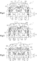
figures 4 à 6 sont des vues schématiques de face de la banquette de lafigure 1 , sur lesquelles sont respectivement représentés deux, trois et quatre passagers assis sur la banquette.
- the
figure 1 is a schematic perspective view of a seat according to the invention; - the
figure 2 is a detail view of zone II of thefigure 1 ; - the
figure 3 is a schematic front view of the webbing guide of the bench of thefigure 1 ; and - the
Figures 4 to 6 are schematic views from the front of the bench of thefigure 1 , on which are respectively represented two, three and four passengers sitting on the seat.
De manière classique, un véhicule automobile 1 comporte un châssis 2 qui comprend notamment un plancher, deux ailes latérales et un toit (voir
Ce véhicule automobile 1 comporte ici deux sièges avant et une banquette arrière 10 représentée sur la
Dans la description, les termes « avant » et « arrière » seront utilisés par rapport à ce véhicule automobile, l'avant d'un composant du véhicule automobile désignant le côté de ce composant qui est tourné vers le capot du véhicule et l'arrière désignant le côté de ce composant qui est tourné vers le coffre.In the description, the terms "front" and "rear" will be used with respect to this motor vehicle, the front of a component of the motor vehicle designating the side of this component which is turned towards the hood of the vehicle and the rear designating the side of this component which is turned towards the trunk.
De la même manière, les termes «inférieur » et «supérieur » seront utilisés par rapport à ce véhicule automobile, la partie inférieure d'un composant désignant la partie de ce composant qui est située du côté du plancher du véhicule et la partie supérieure désignant la partie de ce composant qui est située du côté du toit.In the same way, the terms "lower" and "upper" will be used with respect to this motor vehicle, the lower part of a component designating the part of this component which is located on the side of the floor of the vehicle and the upper part designating the part of that component that is located on the roof side.
Bien que l'invention ne se limite pas à ce type de véhicule, on considérera ici que le véhicule automobile est du type « tri-corps ». Un tel véhicule automobile comporte un coffre, un habitacle et un capot qui, vus de côté, forment deux décrochés, l'un au niveau du bas du pare-brise et l'autre au niveau du bas de la lunette arrière.Although the invention is not limited to this type of vehicle, it will be considered here that the motor vehicle is of the "tri-body" type. Such a motor vehicle comprises a trunk, a passenger compartment and a hood which, seen from the side, form two unhooked, one at the bottom of the windshield and the other at the bottom of the rear window.
Sur ce type de véhicule automobile, le châssis comporte une tablette métallique qui s'étend entre les deux ailes latérales, à l'arrière de la banquette 10, au niveau de la jonction entre la lunette arrière et le coffre.On this type of motor vehicle, the chassis comprises a metal shelf which extends between the two side wings, at the rear of the
Comme le montre la
De manière classique, l'assise 20 et le dossier 30 comportent chacun une armature métallique (non visible sur les figures) recouverte d'une garniture pour le confort des passagers.Conventionally, the
L'assise 20 est directement montée sur le plancher du véhicule automobile. Elle y est préférentiellement montée fixement, au moyen de pieds qui, d'un côté, sont soudés à l'armature de l'assise, et qui, de l'autre côté, sont vissés sur le plancher.The
En variante, on pourrait prévoir de monter l'assise sur le plancher avec une unique mobilité de basculement vers l'avant, de manière à pouvoir rabattre l'assise contre les dossiers des sièges avant.Alternatively, one could provide to mount the seat on the floor with a single forward tilting mobility, so as to fold the seat against the back of the front seats.
Le dossier pourrait quant à lui être fixé sur l'assise ou sur le châssis du véhicule.The backrest could be fixed to the seat or the chassis of the vehicle.
Ici, le dossier 30 est plutôt monté mobile sur l'assise 20, au moyen d'une charnière lui permettant de basculer vers l'avant.Here, the
Le dossier 30 est ainsi mobile entre une position d'utilisation dans laquelle il s'étend verticalement de manière qu'un passager puisse s'asseoir sur la banquette 10, et une position rabattue dans laquelle il s'étend horizontalement contre l'assise afin de libérer de l'espace de chargement dans le coffre du véhicule automobile.The
Préférentiellement, l'assise 20 et le dossier 30 sont monoblocs, en ce sens qu'ils comportent chacun une armature métallique rigide. Le dossier 30 comme l'assise 20 ne sont donc pas fractionnables : ils ne sont pas ici prévus pour pouvoir être rabattus partiellement.Preferably, the
Ce dossier 30 présente un bord inférieur 31 qui, en position d'utilisation, est tourné vers l'assise 20. Il présente également un bord supérieur 32 opposé (tourné vers le toit du véhicule automobile), et deux bords latéraux (respectivement tournés vers les ailes latérales du véhicule automobile).This
Comme le montre la
Comme le montre la
Classiquement, ces appuis-tête 40 comportent chacun une armature métallique recouverte d'une garniture, ainsi que deux tiges parallèles 41 qui sont soudées à l'armature de l'appui-tête 40 et qui sont montées coulissantes dans deux douilles fixées à l'ossature métallique du dossier 30 (voir
Chacune des deux douilles précitées, bien connues de l'homme du métier, comporte un fourreau qui est soudé à l'ossature métallique du dossier 30 et qui loge intérieurement une gaine en matière plastique. Cette gaine porte à son extrémité supérieure une collerette qui émerge à l'extérieur du dossier afin de délimiter un passage pour l'un des tiges parallèles 41 de l'appui-tête 40. La gaine permet quant à elle de guider le coulissement de cette tige parallèle 41. Cette gaine comporte par ailleurs des languettes d'encliquetage qui sont adaptées à coopérer avec des crans prévus sur les tiges parallèles 41 pour bloquer en hauteur l'appui-tête 40.Each of the two aforementioned sleeves, well known to those skilled in the art, comprises a sheath which is welded to the metal frame of the
Comme le montre la
Chaque ceinture de sécurité 50, 60, 70, 80 est ici du type à trois points de fixation. Chaque ceinture comporte alors un enrouleur 52, 62, 72, 82 fixé à une partie structurelle du véhicule automobile, une sangle 51, 61, 71, 81 dont une partie est enroulée dans l'enrouleur et dont une autre partie émerge de l'enrouleur, et un pêne 53, 63, 73, 83.Each
Les enrouleurs 72, 82 des deux ceintures de sécurité 70, 80 extérieures (celles situées de part et d'autre de la banquette 10) sont directement fixés aux ailes latérales du véhicule automobile, ici par vissage.The
La sangle 71, 81 de chacune de ces deux ceintures de sécurité 70, 80 extérieures émerge de l'enrouleur 72, 82, passe par un guide 74, 84 qui est fixé à l'une des ailes latérales du véhicule automobile (à hauteur du bord supérieur du dossier 30), puis redescend jusqu'au plancher où son extrémité libre est fixée.The
Comme le montrent les
La sangle 51, 61 de chacune de ces deux ceintures de sécurité 50, 60 centrales émerge de l'enrouleur, passe par un guide-sangle 100 situé entre les deux appuis-tête 40, puis redescend vers le plancher où son extrémité libre est fixée. Chaque sangle 51, 61 passe soit au travers d'un passage prévu dans l'assise 20, soit entre l'assise 20 et le dossier 30.The
La présente invention porte alors plus précisément sur le guide-sangle 100.The present invention thus relates more precisely to the
Selon l'invention, ce guide-sangle 100 est monté mobile sur le dossier 30, à distance des bords latéraux 33 du dossier 30, de façon à présenter une hauteur h réglable par rapport au bord supérieur 32 du dossier 30 (voir
Pour cela, comme le montre la
En l'espèce, le guide-sangle 100 est situé à égales distances des bords latéraux du dossier 30. Selon l'invention il délimite deux passages 125, 126 distincts pour les deux sangles 51, 61 des ceintures de sécurité 50, 60 centrales.In this case, the
Ici, le corps 120 se présente sous la forme d'une plaque rectangulaire, et les moyens de montage 110 se présentent sous la forme de deux tiges 111 qui s'étendent à partir du bord inférieur du corps 120, perpendiculairement à celui-ci.Here, the
Le corps 120 et les deux tiges 111 sont soit formés d'une seule pièce, par emboutissage d'une plaque métallique, soit assemblés pour former une seule pièce monobloc. On pourra prévoir de recouvrir le corps 120 d'une peau en matériau plastique, par exemple en surmoulant la plaque métallique.The
Les deux tiges 111 sont ici identiques à celles équipant les appuis-tête 40. Elles sont alors montées coulissantes dans des gaines en matière plastique logées dans deux douilles soudées à l'ossature métallique du dossier 30. Ces douilles et ces gaines sont ici encore identiques à celles accueillant les tiges 41 des appuis-tête 40.The two
En pratique, le guide-sangle 100 peut ainsi se monter en lieu et place d'un appui-tête central d'une banquette initialement prévue pour accueillir trois passagers uniquement.In practice, the
De cette manière, le corps 120 est mobile par rapport au dossier 30, entre une position haute et une position basse (en appui contre le dossier 30).In this way, the
Les languettes d'encliquetage prévues sur les gaines en matière pastique (logées dans les douilles) sont alors prévues pour coopérer avec des encoches prévues sur les tiges 111 du guide-sangle 100, ce qui permet aux passagers de régler manuellement la hauteur h de ce guide-sangle 100 par rapport au bord supérieur 32 du dossier 30.The snap-fastening tongues provided on the sheaths made of pastic material (housed in the bushes) are then provided to cooperate with notches provided on the
Comme le montre la
Ici, chacun de ces deux passages 125, 126 se présente sous la forme d'une fente, dont une première partie 125A, 126A est légèrement incurvée, et dont une seconde partie 125B, 126B est courbée en demi-cercle.Here, each of these two
Ces deux passages 125, 126 sont positionnés tête-bêche l'un au-dessus de l'autre, si bien que les premières parties 125A, 126A de ces passages 125, 126 sont inclinées l'une par rapport à l'autre, en V.These two
Chaque passage 125, 126 présente ici un contour ouvert. Plus précisément, chaque passage 125, 126 communique avec l'extérieur du guide-sangle 100, via une fente d'engagement 127, 128 qui s'étend depuis le bord du corps 120 jusqu'au passage 125, 126 correspondant.Each
Cette fente d'engagement 127, 128 permet d'insérer ou d'extraire facilement une sangle de ceinture de sécurité dans le passage 125, 126 correspondant.This
Comme le montre la
En l'espèce, chaque pêne comporte, d'une part, un corps qui présente une fente enfilée sur la sangle, et, d'autre part, une plaquette qui s'étend à partir du corps et qui est prévue pour se verrouiller dans un pédoncule.In the present case, each bolt comprises, on the one hand, a body that has a slot slipped on the strap, and, on the other hand, a plate that extends from the body and is intended to lock in a peduncle.
Classiquement, chaque moyen d'ancrage est formé par un pédoncule monté sur un support.Conventionally, each anchoring means is formed by a peduncle mounted on a support.
Selon une caractéristique préférentielle de l'invention, il est prévu davantage de pédoncules 91, 92, 93, 94, 95, 96 que de pênes montés sur les ceintures de sécurité 50, 60, 70, 80.According to a preferred feature of the invention,
En l'espèce, le véhicule automobile comporte, pour la banquette 10, six pédoncules 91, 92, 93, 94, 95, 96 et seulement quatre ceintures de sécurité 50, 60, 70, 80 chacune équipée d'un seul pêne.In the present case, the motor vehicle comprises, for the
Il est plus précisément prévu deux pédoncules 91, 92 extérieurs, qui sont situés de part et d'autre de la banquette 10 et dont les supports sont formés par des tiges fixées au plancher du véhicule automobile.It is more specifically provided two
Il est par ailleurs prévu quatre pédoncules 93, 94, 95, 96 centraux, qui sont répartis par paire le long de l'assise 20, entre les deux pédoncules 91, 92 extérieurs, à distance de ceux-ci.It is further provided four
Les deux pédoncules de chaque paire de pédoncules 93, 94, 95, 96 sont ici fixés sur un même support.The two peduncles of each pair of
Les deux supports sont ici prévus de telle sorte que les quatre pédoncules sont rétractables par rapport à l'assise 20. De cette manière, lorsqu'ils ne sont pas utilisés, ces pédoncules peuvent être placés de telle manière qu'un passager peut s'asseoir par-dessus sans être gêné.The two supports are here provided so that the four pedicels are retractable relative to the
Ici, ces supports sont à cet effet formés par des sangles (non visibles) reliées au plancher du véhicule automobile. Les quatre pédoncules sont quant à eux prévus pour se rétracter soit dans des cavités creusées dans l'assise 20 (voir
Comme le montre la
Pour ne pas être gênés par les ceintures de sécurité 70, 80 latérales (qui ne sont pas utilisées), les deux passagers 200 peuvent (avant de s'asseoir) basculer le dossier 30 vers l'avant de manière à passer les sangles 71, 81 de ces deux ceintures de sécurité 70, 80 à l'arrière du dossier 30, avant de ramener le dossier en position d'utilisation. Des crochets prévus à cet effet à l'arrière du dossier 30 peuvent faciliter le maintien des sangles 71, 81 à l'arrière de la banquette 10.To avoid being bothered by the
Pour ne pas être blessés par les sangles 51, 61 des ceintures de sécurité 50, 60 centrales en cas de choc, les deux passagers 200 peuvent également ajuster la hauteur du guide-sangle 100, en le déplaçant ici en position haute.To avoid being injured by the
Comme le montre la
Pour ne pas être blessés par les sangles 51, 61 des ceintures de sécurité 50, 60 centrales en cas de choc, les deux passagers 400 assis au centre de la banquette 10 peuvent ajuster la hauteur du guide-sangle 100, en le déplaçant ici en position basse.To avoid being injured by the
Comme le montre la
Pour ne pas être blessés par les sangles 51, 61 des ceintures de sécurité 50, 60 centrales en cas de choc, le passager 200 de plus forte corpulence utilise la ceinture de sécurité 50 qui émerge du passage 125 le plus haut du guide-sangle 100, tandis que l'autre passager utilise la ceinture de sécurité 60 qui émerge du passage 126 le plus bas du guide-sangle 100. L'intérêt d'avoir deux passages 125, 126 superposés est ainsi de permettre à chaque passager d'utiliser une ceinture de sécurité dont la sangle est correctement positionnée en hauteur par rapport à son épaule.To avoid being injured by the
Claims (8)
- Motor vehicle bench seat (10) comprising a seat part (20) and a backrest (30) which has a lower edge (31) facing the seat part (20), an opposite upper edge (32), and two lateral edges (33),
characterized in that it comprises a webbing guide (100) for seat belt webbing, which is mounted in a movable manner on the backrest (30), at a distance from the lateral edges (33), so as to have a height (h) that is adjustable with respect to the upper edge (32) of the backrest (30), and which comprises a body (120) that delimits two distinct passages (125, 126) for two webbings (51, 61) of seat belts (50, 60) and wherein the two passages (125, 126) are superposed. - Bench seat (10) according to the preceding claim, wherein the webbing guide (100) is situated at an equal distance from the two lateral edges (33) of the backrest (30) .
- Bench seat (10) according to either of the preceding claims, wherein the backrest (30) comprises an inner frame which is covered with trim and which bears at least one pair of bushings (35) for mounting a headrest (40), and wherein the webbing guide (100) comprises a pair of stems (111) mounted so as to be able to move in translation in said pair of bushings (35).
- Bench seat (10) according to the preceding claim, wherein the inner frame of the backrest (30) bears two other pairs of bushings, and wherein two headrests (40) are provided, which each comprise a pair of stems (41) mounted so as to be able to move in translation in said other pairs of bushings.
- Bench seat (10) according to one of the preceding claims, wherein each passage (125, 126) has an open contour which opens laterally onto the outside of the body (120) through an insertion slot (127, 128).
- Motor vehicle (1) comprising a chassis (2) and two central seat belts (50, 60) that each comprise webbing (51, 61), characterized in that it comprises a bench seat (10) according to one of the preceding claims, which is mounted on the chassis and the webbing guide (100) of which allows the passage of the webbings (51, 61) of the two central seat belts (50, 60).
- Motor vehicle (1) according to the preceding claim, wherein more buckles (91, 92, 93, 94, 95, 96) for seat belt tongues are provided than tongues mounted on the seat belts (50, 60, 70, 80).
- Motor vehicle (1) according to the preceding claim, wherein the following are provided:- two outer seat belts (70, 80) that are situated on either side of the bench seat (10),- two outer buckles (91, 92) for seat belt tongues, which are situated on either side of the bench seat (10), and- four central buckles (93, 94, 95, 96) for seat belt tongues, which are distributed in pairs along the seat part (20), between the two outer buckles (91, 92) and at a distance therefrom.
Applications Claiming Priority (2)
| Application Number | Priority Date | Filing Date | Title |
|---|---|---|---|
| FR1456197A FR3022876B1 (en) | 2014-06-30 | 2014-06-30 | MOTOR VEHICLE BENCH, COMPRISING A STRAP GUIDE FOR A SEAT BELT |
| PCT/FR2015/051768 WO2016001559A1 (en) | 2014-06-30 | 2015-06-29 | Motor vehicle seat comprising a strap guide for a safety belt |
Publications (2)
| Publication Number | Publication Date |
|---|---|
| EP3160802A1 EP3160802A1 (en) | 2017-05-03 |
| EP3160802B1 true EP3160802B1 (en) | 2019-01-30 |
Family
ID=51659827
Family Applications (1)
| Application Number | Title | Priority Date | Filing Date |
|---|---|---|---|
| EP15742357.5A Active EP3160802B1 (en) | 2014-06-30 | 2015-06-29 | Motor vehicle seat comprising a strap guide for a safety belt |
Country Status (4)
| Country | Link |
|---|---|
| EP (1) | EP3160802B1 (en) |
| CN (1) | CN106660512B (en) |
| FR (1) | FR3022876B1 (en) |
| WO (1) | WO2016001559A1 (en) |
Cited By (1)
| Publication number | Priority date | Publication date | Assignee | Title |
|---|---|---|---|---|
| DE102019206965B4 (en) | 2019-05-14 | 2024-01-25 | Pössl Freizeit und Sport GmbH | Belt system for a vehicle |
Citations (1)
| Publication number | Priority date | Publication date | Assignee | Title |
|---|---|---|---|---|
| DE10311281B3 (en) * | 2003-03-14 | 2004-10-07 | Wilhelm Karmann Gmbh | Safety belt arrangement for car seats arranged next to each other has belts which are guided across roller devices |
Family Cites Families (6)
| Publication number | Priority date | Publication date | Assignee | Title |
|---|---|---|---|---|
| DE1430468A1 (en) * | 1964-03-11 | 1968-11-28 | Autoflug Gerhard Sedlmayr Gmbh | Safety seat, especially for motor vehicles |
| JPS58121741U (en) * | 1982-02-12 | 1983-08-19 | トヨタ自動車株式会社 | seat belt guide |
| US6305713B1 (en) * | 1999-12-27 | 2001-10-23 | General Motors Corporation | Four point restraint apparatus |
| CN101421136B (en) * | 2005-12-19 | 2011-06-22 | 安全带私人有限公司 | A seatbelt restraint |
| CN102923030B (en) * | 2012-11-22 | 2017-04-19 | 上海延锋江森座椅有限公司 | Automobile twin seat framework |
| CN203611924U (en) * | 2013-12-06 | 2014-05-28 | 北汽福田汽车股份有限公司 | Double seat and automobile |
-
2014
- 2014-06-30 FR FR1456197A patent/FR3022876B1/en not_active Expired - Fee Related
-
2015
- 2015-06-29 EP EP15742357.5A patent/EP3160802B1/en active Active
- 2015-06-29 CN CN201580041273.3A patent/CN106660512B/en active Active
- 2015-06-29 WO PCT/FR2015/051768 patent/WO2016001559A1/en active Application Filing
Patent Citations (1)
| Publication number | Priority date | Publication date | Assignee | Title |
|---|---|---|---|---|
| DE10311281B3 (en) * | 2003-03-14 | 2004-10-07 | Wilhelm Karmann Gmbh | Safety belt arrangement for car seats arranged next to each other has belts which are guided across roller devices |
Cited By (1)
| Publication number | Priority date | Publication date | Assignee | Title |
|---|---|---|---|---|
| DE102019206965B4 (en) | 2019-05-14 | 2024-01-25 | Pössl Freizeit und Sport GmbH | Belt system for a vehicle |
Also Published As
| Publication number | Publication date |
|---|---|
| FR3022876B1 (en) | 2017-12-08 |
| FR3022876A1 (en) | 2016-01-01 |
| WO2016001559A1 (en) | 2016-01-07 |
| EP3160802A1 (en) | 2017-05-03 |
| CN106660512A (en) | 2017-05-10 |
| CN106660512B (en) | 2019-06-21 |
Similar Documents
| Publication | Publication Date | Title |
|---|---|---|
| US7063389B2 (en) | Seat belt assembly system | |
| FR2981018A1 (en) | CHILDREN'S CAR SEAT, SEAT ADJUSTABLE IN HEIGHT | |
| EP3400150B1 (en) | Seat and base for the transport of a child in a vehicle | |
| EP3160802B1 (en) | Motor vehicle seat comprising a strap guide for a safety belt | |
| EP2678211B1 (en) | Assembly for attaching a steering column for a motor vehicle | |
| FR3022875A1 (en) | MOTOR VEHICLE HAVING A FOUR-SQUARED BENCH | |
| FR3022873A1 (en) | SEAT BELT GUIDE FOR MOTOR VEHICLE | |
| EP1122135B1 (en) | Vehicle rear seat, its seatbelt buckles with adjustable fixing position | |
| EP3737590B1 (en) | Arrangement of a partition for an interior loading space of a utility vehicle, and vehicle comprising such an arrangement | |
| EP1728692B1 (en) | Movable seat for a motor vehicle with a seat belt system | |
| EP3233585B1 (en) | Retractor support of a rear seat belt of a motor vehicle | |
| WO2006117487A1 (en) | Seat assembly for a motor vehicle | |
| EP3164294B1 (en) | Seat for motor vehicle and mounting method | |
| EP1721777A2 (en) | Adjustable vehicle bench seat | |
| FR3034062A3 (en) | SEAT OF A MOTOR VEHICLE EQUIPPED WITH A SECURITY BELT REEL | |
| WO2005051703A1 (en) | Seat for a motor vehicle, and motor vehicle equipped with this seat | |
| FR3042156A1 (en) | ACCOMMODATION SEAT FOR A TRANSPORT VEHICLE COMPRISING A RETRACTABLE SAFETY BELT HOUSING | |
| US8444221B2 (en) | Booster seat assembly | |
| EP1776259A1 (en) | Retaining means arrangement inside a motor vehicle | |
| EP3532341B1 (en) | Modular seat for a motor vehicle | |
| EP3722148A1 (en) | Seat with reclining and folding back | |
| FR3113876A1 (en) | VEHICLE BODY WITH REINFORCEMENT BETWEEN THE PARTITION WALL AND THE WHEEL ARCH | |
| FR3103748A1 (en) | Motor vehicle rear floor element | |
| EP3984859A1 (en) | Modular sledge | |
| EP1234712A1 (en) | Base frame for automotive vehicle seat and method for mounting such a base frame |
Legal Events
| Date | Code | Title | Description |
|---|---|---|---|
| STAA | Information on the status of an ep patent application or granted ep patent |
Free format text: STATUS: THE INTERNATIONAL PUBLICATION HAS BEEN MADE |
|
| PUAI | Public reference made under article 153(3) epc to a published international application that has entered the european phase |
Free format text: ORIGINAL CODE: 0009012 |
|
| STAA | Information on the status of an ep patent application or granted ep patent |
Free format text: STATUS: REQUEST FOR EXAMINATION WAS MADE |
|
| 17P | Request for examination filed |
Effective date: 20170120 |
|
| AK | Designated contracting states |
Kind code of ref document: A1 Designated state(s): AL AT BE BG CH CY CZ DE DK EE ES FI FR GB GR HR HU IE IS IT LI LT LU LV MC MK MT NL NO PL PT RO RS SE SI SK SM TR |
|
| AX | Request for extension of the european patent |
Extension state: BA ME |
|
| DAV | Request for validation of the european patent (deleted) | ||
| DAX | Request for extension of the european patent (deleted) | ||
| STAA | Information on the status of an ep patent application or granted ep patent |
Free format text: STATUS: EXAMINATION IS IN PROGRESS |
|
| 17Q | First examination report despatched |
Effective date: 20180102 |
|
| GRAP | Despatch of communication of intention to grant a patent |
Free format text: ORIGINAL CODE: EPIDOSNIGR1 |
|
| STAA | Information on the status of an ep patent application or granted ep patent |
Free format text: STATUS: GRANT OF PATENT IS INTENDED |
|
| INTG | Intention to grant announced |
Effective date: 20180904 |
|
| RIN1 | Information on inventor provided before grant (corrected) |
Inventor name: GUICHERD, OLIVIER Inventor name: RICHEZ, EMMANUEL |
|
| GRAS | Grant fee paid |
Free format text: ORIGINAL CODE: EPIDOSNIGR3 |
|
| GRAA | (expected) grant |
Free format text: ORIGINAL CODE: 0009210 |
|
| STAA | Information on the status of an ep patent application or granted ep patent |
Free format text: STATUS: THE PATENT HAS BEEN GRANTED |
|
| AK | Designated contracting states |
Kind code of ref document: B1 Designated state(s): AL AT BE BG CH CY CZ DE DK EE ES FI FR GB GR HR HU IE IS IT LI LT LU LV MC MK MT NL NO PL PT RO RS SE SI SK SM TR |
|
| REG | Reference to a national code |
Ref country code: GB Ref legal event code: FG4D Free format text: NOT ENGLISH |
|
| REG | Reference to a national code |
Ref country code: CH Ref legal event code: EP |
|
| REG | Reference to a national code |
Ref country code: AT Ref legal event code: REF Ref document number: 1092990 Country of ref document: AT Kind code of ref document: T Effective date: 20190215 |
|
| REG | Reference to a national code |
Ref country code: IE Ref legal event code: FG4D Free format text: LANGUAGE OF EP DOCUMENT: FRENCH |
|
| REG | Reference to a national code |
Ref country code: DE Ref legal event code: R096 Ref document number: 602015024034 Country of ref document: DE |
|
| REG | Reference to a national code |
Ref country code: LT Ref legal event code: MG4D |
|
| REG | Reference to a national code |
Ref country code: NL Ref legal event code: MP Effective date: 20190130 |
|
| PG25 | Lapsed in a contracting state [announced via postgrant information from national office to epo] |
Ref country code: NO Free format text: LAPSE BECAUSE OF FAILURE TO SUBMIT A TRANSLATION OF THE DESCRIPTION OR TO PAY THE FEE WITHIN THE PRESCRIBED TIME-LIMIT Effective date: 20190430 Ref country code: PT Free format text: LAPSE BECAUSE OF FAILURE TO SUBMIT A TRANSLATION OF THE DESCRIPTION OR TO PAY THE FEE WITHIN THE PRESCRIBED TIME-LIMIT Effective date: 20190530 Ref country code: FI Free format text: LAPSE BECAUSE OF FAILURE TO SUBMIT A TRANSLATION OF THE DESCRIPTION OR TO PAY THE FEE WITHIN THE PRESCRIBED TIME-LIMIT Effective date: 20190130 Ref country code: SE Free format text: LAPSE BECAUSE OF FAILURE TO SUBMIT A TRANSLATION OF THE DESCRIPTION OR TO PAY THE FEE WITHIN THE PRESCRIBED TIME-LIMIT Effective date: 20190130 Ref country code: ES Free format text: LAPSE BECAUSE OF FAILURE TO SUBMIT A TRANSLATION OF THE DESCRIPTION OR TO PAY THE FEE WITHIN THE PRESCRIBED TIME-LIMIT Effective date: 20190130 Ref country code: PL Free format text: LAPSE BECAUSE OF FAILURE TO SUBMIT A TRANSLATION OF THE DESCRIPTION OR TO PAY THE FEE WITHIN THE PRESCRIBED TIME-LIMIT Effective date: 20190130 Ref country code: LT Free format text: LAPSE BECAUSE OF FAILURE TO SUBMIT A TRANSLATION OF THE DESCRIPTION OR TO PAY THE FEE WITHIN THE PRESCRIBED TIME-LIMIT Effective date: 20190130 Ref country code: NL Free format text: LAPSE BECAUSE OF FAILURE TO SUBMIT A TRANSLATION OF THE DESCRIPTION OR TO PAY THE FEE WITHIN THE PRESCRIBED TIME-LIMIT Effective date: 20190130 |
|
| REG | Reference to a national code |
Ref country code: AT Ref legal event code: MK05 Ref document number: 1092990 Country of ref document: AT Kind code of ref document: T Effective date: 20190130 |
|
| PG25 | Lapsed in a contracting state [announced via postgrant information from national office to epo] |
Ref country code: LV Free format text: LAPSE BECAUSE OF FAILURE TO SUBMIT A TRANSLATION OF THE DESCRIPTION OR TO PAY THE FEE WITHIN THE PRESCRIBED TIME-LIMIT Effective date: 20190130 Ref country code: GR Free format text: LAPSE BECAUSE OF FAILURE TO SUBMIT A TRANSLATION OF THE DESCRIPTION OR TO PAY THE FEE WITHIN THE PRESCRIBED TIME-LIMIT Effective date: 20190501 Ref country code: HR Free format text: LAPSE BECAUSE OF FAILURE TO SUBMIT A TRANSLATION OF THE DESCRIPTION OR TO PAY THE FEE WITHIN THE PRESCRIBED TIME-LIMIT Effective date: 20190130 Ref country code: IS Free format text: LAPSE BECAUSE OF FAILURE TO SUBMIT A TRANSLATION OF THE DESCRIPTION OR TO PAY THE FEE WITHIN THE PRESCRIBED TIME-LIMIT Effective date: 20190530 Ref country code: BG Free format text: LAPSE BECAUSE OF FAILURE TO SUBMIT A TRANSLATION OF THE DESCRIPTION OR TO PAY THE FEE WITHIN THE PRESCRIBED TIME-LIMIT Effective date: 20190430 Ref country code: RS Free format text: LAPSE BECAUSE OF FAILURE TO SUBMIT A TRANSLATION OF THE DESCRIPTION OR TO PAY THE FEE WITHIN THE PRESCRIBED TIME-LIMIT Effective date: 20190130 |
|
| PG25 | Lapsed in a contracting state [announced via postgrant information from national office to epo] |
Ref country code: DK Free format text: LAPSE BECAUSE OF FAILURE TO SUBMIT A TRANSLATION OF THE DESCRIPTION OR TO PAY THE FEE WITHIN THE PRESCRIBED TIME-LIMIT Effective date: 20190130 Ref country code: IT Free format text: LAPSE BECAUSE OF FAILURE TO SUBMIT A TRANSLATION OF THE DESCRIPTION OR TO PAY THE FEE WITHIN THE PRESCRIBED TIME-LIMIT Effective date: 20190130 Ref country code: EE Free format text: LAPSE BECAUSE OF FAILURE TO SUBMIT A TRANSLATION OF THE DESCRIPTION OR TO PAY THE FEE WITHIN THE PRESCRIBED TIME-LIMIT Effective date: 20190130 Ref country code: RO Free format text: LAPSE BECAUSE OF FAILURE TO SUBMIT A TRANSLATION OF THE DESCRIPTION OR TO PAY THE FEE WITHIN THE PRESCRIBED TIME-LIMIT Effective date: 20190130 Ref country code: AL Free format text: LAPSE BECAUSE OF FAILURE TO SUBMIT A TRANSLATION OF THE DESCRIPTION OR TO PAY THE FEE WITHIN THE PRESCRIBED TIME-LIMIT Effective date: 20190130 Ref country code: CZ Free format text: LAPSE BECAUSE OF FAILURE TO SUBMIT A TRANSLATION OF THE DESCRIPTION OR TO PAY THE FEE WITHIN THE PRESCRIBED TIME-LIMIT Effective date: 20190130 Ref country code: SK Free format text: LAPSE BECAUSE OF FAILURE TO SUBMIT A TRANSLATION OF THE DESCRIPTION OR TO PAY THE FEE WITHIN THE PRESCRIBED TIME-LIMIT Effective date: 20190130 |
|
| REG | Reference to a national code |
Ref country code: DE Ref legal event code: R097 Ref document number: 602015024034 Country of ref document: DE |
|
| PG25 | Lapsed in a contracting state [announced via postgrant information from national office to epo] |
Ref country code: SM Free format text: LAPSE BECAUSE OF FAILURE TO SUBMIT A TRANSLATION OF THE DESCRIPTION OR TO PAY THE FEE WITHIN THE PRESCRIBED TIME-LIMIT Effective date: 20190130 |
|
| PLBE | No opposition filed within time limit |
Free format text: ORIGINAL CODE: 0009261 |
|
| STAA | Information on the status of an ep patent application or granted ep patent |
Free format text: STATUS: NO OPPOSITION FILED WITHIN TIME LIMIT |
|
| PG25 | Lapsed in a contracting state [announced via postgrant information from national office to epo] |
Ref country code: AT Free format text: LAPSE BECAUSE OF FAILURE TO SUBMIT A TRANSLATION OF THE DESCRIPTION OR TO PAY THE FEE WITHIN THE PRESCRIBED TIME-LIMIT Effective date: 20190130 |
|
| 26N | No opposition filed |
Effective date: 20191031 |
|
| PG25 | Lapsed in a contracting state [announced via postgrant information from national office to epo] |
Ref country code: MC Free format text: LAPSE BECAUSE OF FAILURE TO SUBMIT A TRANSLATION OF THE DESCRIPTION OR TO PAY THE FEE WITHIN THE PRESCRIBED TIME-LIMIT Effective date: 20190130 |
|
| REG | Reference to a national code |
Ref country code: CH Ref legal event code: PL |
|
| PG25 | Lapsed in a contracting state [announced via postgrant information from national office to epo] |
Ref country code: SI Free format text: LAPSE BECAUSE OF FAILURE TO SUBMIT A TRANSLATION OF THE DESCRIPTION OR TO PAY THE FEE WITHIN THE PRESCRIBED TIME-LIMIT Effective date: 20190130 |
|
| REG | Reference to a national code |
Ref country code: BE Ref legal event code: MM Effective date: 20190630 |
|
| PG25 | Lapsed in a contracting state [announced via postgrant information from national office to epo] |
Ref country code: TR Free format text: LAPSE BECAUSE OF FAILURE TO SUBMIT A TRANSLATION OF THE DESCRIPTION OR TO PAY THE FEE WITHIN THE PRESCRIBED TIME-LIMIT Effective date: 20190130 |
|
| PG25 | Lapsed in a contracting state [announced via postgrant information from national office to epo] |
Ref country code: IE Free format text: LAPSE BECAUSE OF NON-PAYMENT OF DUE FEES Effective date: 20190629 |
|
| PG25 | Lapsed in a contracting state [announced via postgrant information from national office to epo] |
Ref country code: CH Free format text: LAPSE BECAUSE OF NON-PAYMENT OF DUE FEES Effective date: 20190630 Ref country code: LI Free format text: LAPSE BECAUSE OF NON-PAYMENT OF DUE FEES Effective date: 20190630 Ref country code: BE Free format text: LAPSE BECAUSE OF NON-PAYMENT OF DUE FEES Effective date: 20190630 Ref country code: LU Free format text: LAPSE BECAUSE OF NON-PAYMENT OF DUE FEES Effective date: 20190629 |
|
| PG25 | Lapsed in a contracting state [announced via postgrant information from national office to epo] |
Ref country code: CY Free format text: LAPSE BECAUSE OF FAILURE TO SUBMIT A TRANSLATION OF THE DESCRIPTION OR TO PAY THE FEE WITHIN THE PRESCRIBED TIME-LIMIT Effective date: 20190130 |
|
| PG25 | Lapsed in a contracting state [announced via postgrant information from national office to epo] |
Ref country code: MT Free format text: LAPSE BECAUSE OF FAILURE TO SUBMIT A TRANSLATION OF THE DESCRIPTION OR TO PAY THE FEE WITHIN THE PRESCRIBED TIME-LIMIT Effective date: 20190130 Ref country code: HU Free format text: LAPSE BECAUSE OF FAILURE TO SUBMIT A TRANSLATION OF THE DESCRIPTION OR TO PAY THE FEE WITHIN THE PRESCRIBED TIME-LIMIT; INVALID AB INITIO Effective date: 20150629 |
|
| PG25 | Lapsed in a contracting state [announced via postgrant information from national office to epo] |
Ref country code: MK Free format text: LAPSE BECAUSE OF FAILURE TO SUBMIT A TRANSLATION OF THE DESCRIPTION OR TO PAY THE FEE WITHIN THE PRESCRIBED TIME-LIMIT Effective date: 20190130 |
|
| P01 | Opt-out of the competence of the unified patent court (upc) registered |
Effective date: 20230608 |
|
| PGFP | Annual fee paid to national office [announced via postgrant information from national office to epo] |
Ref country code: FR Payment date: 20230630 Year of fee payment: 9 Ref country code: DE Payment date: 20230620 Year of fee payment: 9 |
|
| PGFP | Annual fee paid to national office [announced via postgrant information from national office to epo] |
Ref country code: GB Payment date: 20230622 Year of fee payment: 9 |
|
| PGFP | Annual fee paid to national office [announced via postgrant information from national office to epo] |
Ref country code: FR Payment date: 20230721 Year of fee payment: 9 |