EP3160802B1 - Kraftfahrzeugsitz mit einer gurtführung für einen sicherheitsgurt - Google Patents
Kraftfahrzeugsitz mit einer gurtführung für einen sicherheitsgurt Download PDFInfo
- Publication number
- EP3160802B1 EP3160802B1 EP15742357.5A EP15742357A EP3160802B1 EP 3160802 B1 EP3160802 B1 EP 3160802B1 EP 15742357 A EP15742357 A EP 15742357A EP 3160802 B1 EP3160802 B1 EP 3160802B1
- Authority
- EP
- European Patent Office
- Prior art keywords
- seat
- backrest
- motor vehicle
- belts
- bench
- Prior art date
- Legal status (The legal status is an assumption and is not a legal conclusion. Google has not performed a legal analysis and makes no representation as to the accuracy of the status listed.)
- Active
Links
- 210000002105 tongue Anatomy 0.000 claims description 5
- 238000003780 insertion Methods 0.000 claims description 3
- 230000037431 insertion Effects 0.000 claims description 3
- 239000002184 metal Substances 0.000 description 9
- 210000004197 pelvis Anatomy 0.000 description 4
- 238000004873 anchoring Methods 0.000 description 2
- 238000012423 maintenance Methods 0.000 description 2
- 230000035939 shock Effects 0.000 description 2
- 208000031968 Cadaver Diseases 0.000 description 1
- 241001080024 Telles Species 0.000 description 1
- 239000000463 material Substances 0.000 description 1
- 230000001105 regulatory effect Effects 0.000 description 1
Images

Classifications
-
- B—PERFORMING OPERATIONS; TRANSPORTING
- B60—VEHICLES IN GENERAL
- B60R—VEHICLES, VEHICLE FITTINGS, OR VEHICLE PARTS, NOT OTHERWISE PROVIDED FOR
- B60R22/00—Safety belts or body harnesses in vehicles
- B60R22/18—Anchoring devices
-
- B—PERFORMING OPERATIONS; TRANSPORTING
- B60—VEHICLES IN GENERAL
- B60N—SEATS SPECIALLY ADAPTED FOR VEHICLES; VEHICLE PASSENGER ACCOMMODATION NOT OTHERWISE PROVIDED FOR
- B60N2/00—Seats specially adapted for vehicles; Arrangement or mounting of seats in vehicles
- B60N2/68—Seat frames
- B60N2/688—Particular seat belt attachment and guiding
-
- B—PERFORMING OPERATIONS; TRANSPORTING
- B60—VEHICLES IN GENERAL
- B60R—VEHICLES, VEHICLE FITTINGS, OR VEHICLE PARTS, NOT OTHERWISE PROVIDED FOR
- B60R22/00—Safety belts or body harnesses in vehicles
- B60R22/18—Anchoring devices
- B60R22/26—Anchoring devices secured to the seat
-
- B—PERFORMING OPERATIONS; TRANSPORTING
- B60—VEHICLES IN GENERAL
- B60R—VEHICLES, VEHICLE FITTINGS, OR VEHICLE PARTS, NOT OTHERWISE PROVIDED FOR
- B60R22/00—Safety belts or body harnesses in vehicles
- B60R22/18—Anchoring devices
- B60R2022/1818—Belt guides
-
- B—PERFORMING OPERATIONS; TRANSPORTING
- B60—VEHICLES IN GENERAL
- B60R—VEHICLES, VEHICLE FITTINGS, OR VEHICLE PARTS, NOT OTHERWISE PROVIDED FOR
- B60R22/00—Safety belts or body harnesses in vehicles
- B60R22/18—Anchoring devices
- B60R22/20—Anchoring devices adjustable in position, e.g. in height
- B60R2022/207—Horizontally or transversally adjustable
-
- B—PERFORMING OPERATIONS; TRANSPORTING
- B60—VEHICLES IN GENERAL
- B60R—VEHICLES, VEHICLE FITTINGS, OR VEHICLE PARTS, NOT OTHERWISE PROVIDED FOR
- B60R22/00—Safety belts or body harnesses in vehicles
- B60R22/18—Anchoring devices
- B60R22/26—Anchoring devices secured to the seat
- B60R2022/266—Rear seats, e.g. benches
Definitions
- the present invention relates generally to the safety of passengers in a motor vehicle.
- a motor vehicle seat comprising a seat and a backrest which has a bottom edge facing the seat, an opposite upper edge, and two side edges.
- It also relates to a motor vehicle comprising a frame, a bench as mentioned above, and two central seatbelts each comprising a strap.
- a motor vehicle has two or three rows of seats.
- the second row of seats is designed to accommodate a variable number of passengers, depending on the type of vehicle.
- the seat belts of the two side seats are of the "three-point attachment" type, in that the strap of each seat belt is attached to a first point on one side of the passenger's pelvis. , pass in front of the passenger's pelvis to a second point, then back across the passenger's chest to a third point above the first point.
- Such a seat belt ensures a good support of the passenger in case of shock.
- the seat-belt of the seat of the seat is of the "two point-of-attachment" type, in that the strap of the seat belt is attached to a first point on one side of the pelvis, and it simply passes over. in front of the passenger's pelvis to a second point of attachment.
- Such a seat belt ensures a less effective maintenance of the passenger in case of impact.
- the present invention proposes replacing the two-point seat belts with three-point seat belts, while complying with the regulatory standards in force. .
- a seat as defined in the introduction which comprises a strap guide for seat belt webbing, which is mounted movable on the backrest, away from the side edges of this folder, so as to have an adjustable height relative to the upper edge of the folder, and which comprises a body defining two separate passages for two belts of seat belts and wherein the two passages are superimposed.
- this strap guide constitutes a third point of attachment for the seat belt strap (s) assigned to the passenger (s) sitting in the center of the seat, in that it will allow to guide each strap from a strap retractor to above the shoulder of this (s) passenger (s).
- the mobile assembly height of the strap guide relative to the backrest will allow him to adjust the height of the third fixing point depending on the size of the passenger. In this way, the seatbelt webbing will be properly adjusted to the passenger's torso so that in the event of a crash, it will not hurt the passenger.
- this strap guide By placing itself in the event that the seat is likely to accommodate up to four passengers, this strap guide will be located substantially equidistant from the lateral edges of the backrest.
- the invention also relates to a motor vehicle as defined in the introduction, in which there is provided a bench as defined previously, which is mounted on the frame and the strap guide allows the passage of the two belts central safety belts.
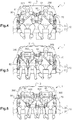
- a motor vehicle 1 comprises a chassis 2 which notably comprises a floor, two lateral wings and a roof (see Figures 4 to 6 ).
- This motor vehicle 1 here comprises two front seats and a rear seat 10 shown on the figure 1 .
- front and rear will be used with respect to this motor vehicle, the front of a component of the motor vehicle designating the side of this component which is turned towards the hood of the vehicle and the rear designating the side of this component which is turned towards the trunk.
- the motor vehicle is of the "tri-body" type.
- a motor vehicle comprises a trunk, a passenger compartment and a hood which, seen from the side, form two unhooked, one at the bottom of the windshield and the other at the bottom of the rear window.
- the chassis comprises a metal shelf which extends between the two side wings, at the rear of the seat 10, at the junction between the rear window and the trunk.
- the seat 10 has a seat 20 and a backrest 30. It is here provided to accommodate up to four passengers.
- the seat 20 and the backrest 30 each comprise a metal frame (not visible in the figures) covered with a pad for the comfort of passengers.
- the seat 20 is directly mounted on the floor of the motor vehicle. It is preferably mounted fixedly, by means of feet which, on one side, are welded to the frame of the seat, and which, on the other side, are screwed on the floor.
- the backrest could be fixed to the seat or the chassis of the vehicle.
- the backrest 30 is rather movably mounted on the seat 20, by means of a hinge allowing it to tilt forward.
- the backrest 30 is thus movable between a position of use in which it extends vertically so that a passenger can sit on the seat 10, and a folded position in which it extends horizontally against the seat to free up cargo space in the trunk of the motor vehicle.
- the seat 20 and the backrest 30 are monoblock, in that they each comprise a rigid metal frame.
- the folder 30 as the seat 20 are not breakable: they are not here provided to be partially folded.
- This backrest 30 has a lower edge 31 which, in the position of use, is turned towards the seat 20. It also has an opposite upper edge 32 (turned towards the roof of the motor vehicle), and two lateral edges (respectively turned towards the side wings of the motor vehicle).
- the seat 10 has exactly two headrests 40 which are fixed to the upper edge 32 of the backrest 30.
- each headrest 40 has a width such that when the seat 10 accommodates four passengers 300, 400, it extends to the rear of the heads of two of the passengers 300, 400.
- these headrests 40 each comprise a metal frame covered with a lining, and two parallel rods 41 which are welded to the frame of the headrest 40 and which are slidably mounted in two sockets fixed to the metal frame of the backrest 30 (see figure 1 ). In this way, the two headrests 40 are movable relative to the backrest 30, between a high position and a low position (bearing against the backrest 30).
- Each of the two aforementioned sleeves comprises a sheath which is welded to the metal frame of the backrest 30 and which lodges a plastic sheath internally.
- This sheath has at its upper end a flange that emerges outside the backrest to define a passage for one of the parallel rods 41 of the headrest 40.
- the sheath is used to guide the sliding of this Parallel rod 41.
- This sheath also comprises locking tabs which are adapted to cooperate with notches provided on parallel rods 41 to lock the headrest 40 upwardly.
- the motor vehicle is also equipped with four seat belts 50, 60, 70, 80 for the four passengers.
- Each seat belt 50, 60, 70, 80 is here of the type with three attachment points.
- Each belt then comprises a retractor 52, 62, 72, 82 fixed to a structural part of the motor vehicle, a strap 51, 61, 71, 81 a part of which is wound in the reel and another part emerges from the reel, and a bolt 53, 63, 73, 83.
- the reels 72, 82 of the two outer seat belts 70, 80 are directly attached to the lateral wings of the motor vehicle, here by screwing.
- the strap 71, 81 of each of these two outer seat belts 70, 80 emerges from the reel 72, 82, passes through a guide 74, 84 which is fixed to one of the lateral wings of the motor vehicle (at upper edge of the backrest 30), then down to the floor where its free end is fixed.
- the reels 52, 62 of the two central safety belts 50, 60 are fixed to the rear shelf (not shown) of the frame, for example by screwing.
- each of these two central seat belts 50, 60 emerges from the reel, passes through a strap guide 100 located between the two headrests 40, then back down to the floor where its free end is fixed .
- Each strap 51, 61 passes either through a passage provided in the seat 20, or between the seat 20 and the backrest 30.
- the present invention thus relates more precisely to the webbing guide 100.
- this strap guide 100 is mounted movably on the backrest 30, away from the lateral edges 33 of the backrest 30, so as to have a height h adjustable relative to the upper edge 32 of the backrest 30 (see FIG. figure 2 ).
- the strap guide 100 comprises mounting means 110 on the backrest 30, and a body 120.
- the strap guide 100 is located at equal distances from the lateral edges of the backrest 30. According to the invention it delimits two passages 125, 126 separate for the two straps 51, 61 of the central safety belts 50, 60.
- the body 120 is in the form of a rectangular plate
- the mounting means 110 are in the form of two rods 111 which extend from the lower edge of the body 120, perpendicular thereto.
- the body 120 and the two rods 111 are either formed in one piece, by stamping a metal plate, or assembled to form a single piece. It may be provided to cover the body 120 with a plastic skin, for example by overmolding the metal plate.
- the two rods 111 are here identical to those fitted to the headrests 40. They are then slidably mounted in plastic sheaths housed in two sockets welded to the metal frame of the backrest 30. These bushings and these sheaths are again identical here. to those accommodating the rods 41 of the headrests 40.
- webbing guide 100 can thus be mounted in place of a central headrest of a bench originally intended to accommodate three passengers only.
- the body 120 is movable relative to the backrest 30, between a high position and a low position (bearing against the backrest 30).
- the snap-fastening tongues provided on the sheaths made of pastic material are then provided to cooperate with notches provided on the stems 111 of the strap guide 100, which allows the passengers to manually adjust the height h of this strap guide 100 with respect to the upper edge 32 of the backrest 30.
- the two passages 125, 126 delimited by the body 120 are superimposed in height (one above the other).
- each of these two passages 125, 126 is in the form of a slot, a first portion 125A, 126A is slightly curved, and a second portion 125B, 126B is curved in a semicircle.
- These two passages 125, 126 are positioned head-to-tail on top of each other, so that the first portions 125A, 126A of these passages 125, 126 are inclined relative to one another, V.
- Each passage 125, 126 here has an open contour. More specifically, each passageway 125, 126 communicates with the outside of the strap guide 100, via an engagement slot 127, 128 which extends from the edge of the body 120 to the corresponding passage 125, 126.
- This engagement slot 127, 128 makes it easy to insert or extract a seat belt strap in the passage 125, 126 corresponding.
- the bolts 53, 63, 73, 83 of the safety belts 50, 60, 70, 80 are designed to be engaged and locked in anchoring means 91, 92, 93, 94, 95, 96 provided at the level of the seat 20 of the bench 10.
- each bolt comprises, on the one hand, a body that has a slot slipped on the strap, and, on the other hand, a plate that extends from the body and is intended to lock in a peduncle.
- each anchoring means is formed by a peduncle mounted on a support.
- more peduncles 91, 92, 93, 94, 95, 96 are provided than bolts mounted on the seat belts 50, 60, 70, 80.
- the motor vehicle comprises, for the seat 10, six pedicles 91, 92, 93, 94, 95, 96 and only four seat belts 50, 60, 70, 80 each equipped with a single bolt.
- peduncles 93, 94, 95, 96 central, which are distributed in pairs along the seat 20, between the two peduncles 91, 92 outside, at a distance thereof.
- the two peduncles of each pair of peduncles 93, 94, 95, 96 are here fixed on the same support.
- the two supports are here provided so that the four pedicels are retractable relative to the seat 20. In this way, when they are not used, these peduncles can be placed in such a way that a passenger can sit on it without being embarrassed.
- these supports are for this purpose formed by straps (not visible) connected to the floor of the motor vehicle.
- the four peduncles are in turn provided to retract either in cavities dug in the seat 20 (see figure 1 ), or at the junction between the seat 20 and the backrest 30.
- the two passengers 200 can (before sitting down) tilt the backrest 30 forward so as to pass the straps 71, 81 of these two seat belts 70, 80 at the rear of the backrest 30, before bringing the backrest to the use position. Hooks provided for this purpose at the back of the backrest 30 can facilitate the maintenance of the straps 71, 81 at the rear of the seat 10.
- the two passengers 200 can also adjust the height of the strap guide 100, moving it here in the high position.
- the two passengers 400 sitting in the center of the seat 10 can adjust the height of the strap guide 100, by moving it here in low position.
- the passenger 200 of larger body builds uses the seat belt 50 which emerges from the passage 125 the highest of the strap guide 100 , while the other passenger uses the seat belt 60 which emerges from the lowest passage 126 of the strap guide 100.
- the advantage of having two passages 125, 126 superimposed is thus to allow each passenger to use a seat belt whose strap is correctly positioned in height relative to his shoulder.
Landscapes
- Engineering & Computer Science (AREA)
- Mechanical Engineering (AREA)
- Aviation & Aerospace Engineering (AREA)
- Transportation (AREA)
- Automotive Seat Belt Assembly (AREA)
- Seats For Vehicles (AREA)
Claims (8)
- Sitzbank (10) eines Kraftfahrzeugs, die eine Sitzfläche (20) und eine Rückenlehne (30) enthält, welche einen zur Sitzfläche (20) weisenden unteren Rand (31), einen gegenüberliegenden oberen Rand (32) und zwei Seitenränder (33) aufweist,
dadurch gekennzeichnet, dass sie eine Gurtführung (100) für ein Gurtband eines Sicherheitsgurts enthält, die in Abstand zu den Seitenrändern (33) beweglich auf die Rückenlehne (30) montiert ist, um eine Höhe (h) aufzuweisen, die bezüglich des oberen Rands (32) der Rückenlehne (30) einstellbar ist, und die einen Körper (120) aufweist, der zwei unterschiedliche Durchgänge (125, 126) für zwei Gurtbänder (51, 61) von Sicherheitsgurten (50, 60) begrenzt und in dem die zwei Durchgänge (125, 126) übereinander angeordnet sind. - Sitzbank (10) nach dem vorhergehenden Anspruch, wobei die Gurtführung (100) sich in gleichem Abstand zu den zwei Seitenrändern (33) der Rückenlehne (30) befindet.
- Sitzbank (10) nach einem der vorhergehenden Ansprüche, wobei die Rückenlehne (30) einen inneren Rahmen aufweist, der mit einem Beschlag bedeckt ist, der mindestens ein Paar von Montagebuchsen (35) einer Kopfstütze (40) trägt, und wobei die Gurtführung (100) ein Paar von Stangen (111) aufweist, die translationsbeweglich in das Paar von Buchsen (35) montiert sind.
- Sitzbank (10) nach dem vorhergehenden Anspruch, wobei der innere Rahmen der Rückenlehne (30) zwei weitere Buchsenpaare aufweist, und wobei zwei Kopfstützen (40) vorgesehen sind, die je ein Paar von Stangen (41) aufweisen, die translationsbeweglich in die zwei anderen Buchsenpaare montiert sind.
- Sitzbank (10) nach einem der vorhergehenden Ansprüche, wobei jeder Durchgang (125, 126) einen offenen Umriss aufweist, der durch einen Einführschlitz (127, 128) seitlich an der Außenseite des Körpers (120) mündet.
- Kraftfahrzeug (1), das einen Aufbau (2) und zwei zentrale Sicherheitsgurte (50, 60) aufweist, die je ein Gurtband (51, 61) aufweisen, dadurch gekennzeichnet, dass es eine Sitzbank (10) nach einem der vorhergehenden Ansprüche aufweist, die auf den Aufbau montiert ist und deren Gurtführung (100) den Durchgang der Gurtbänder (51, 61) der zwei zentralen Sicherheitsgurte (50, 60) erlaubt.
- Kraftfahrzeug (1) nach dem vorhergehenden Anspruch, in dem mehr Gurtschlösser (91, 92, 93, 94, 95, 96) für Sicherheitsgurtriegel als auf die Sicherheitsgurte (50, 60, 70, 80) montierte Riegel vorgesehen sind.
- Kraftfahrzeug (1) nach dem vorhergehenden Anspruch, in dem vorgesehen sind:- zwei äußere Sicherheitsgurte (70, 80), die sich zu beiden Seiten der Sitzbank (10) befinden,- zwei äußere Gurtschlösser (91, 92) für Sicherheitsgurtriegel, die sich zu beiden Seiten der Sitzbank (10) befinden, und- vier zentrale Gurtschlösser (93, 94, 95, 96) für Sicherheitsgurtriegel, die paarweise entlang der Sitzfläche (20) zwischen den zwei äußeren Gurtschlössern (91, 92) und in Abstand zu diesen verteilt sind.
Applications Claiming Priority (2)
| Application Number | Priority Date | Filing Date | Title |
|---|---|---|---|
| FR1456197A FR3022876B1 (fr) | 2014-06-30 | 2014-06-30 | Banquette de vehicule automobile, comprenant un guide-sangle pour ceinture de securite |
| PCT/FR2015/051768 WO2016001559A1 (fr) | 2014-06-30 | 2015-06-29 | Banquette de vehicule automobile comprenant un guide-sangle pour ceinture de securite |
Publications (2)
| Publication Number | Publication Date |
|---|---|
| EP3160802A1 EP3160802A1 (de) | 2017-05-03 |
| EP3160802B1 true EP3160802B1 (de) | 2019-01-30 |
Family
ID=51659827
Family Applications (1)
| Application Number | Title | Priority Date | Filing Date |
|---|---|---|---|
| EP15742357.5A Active EP3160802B1 (de) | 2014-06-30 | 2015-06-29 | Kraftfahrzeugsitz mit einer gurtführung für einen sicherheitsgurt |
Country Status (4)
| Country | Link |
|---|---|
| EP (1) | EP3160802B1 (de) |
| CN (1) | CN106660512B (de) |
| FR (1) | FR3022876B1 (de) |
| WO (1) | WO2016001559A1 (de) |
Cited By (1)
| Publication number | Priority date | Publication date | Assignee | Title |
|---|---|---|---|---|
| DE102019206965B4 (de) | 2019-05-14 | 2024-01-25 | Pössl Freizeit und Sport GmbH | Gurtsystem für ein Fahrzeug |
Citations (1)
| Publication number | Priority date | Publication date | Assignee | Title |
|---|---|---|---|---|
| DE10311281B3 (de) * | 2003-03-14 | 2004-10-07 | Wilhelm Karmann Gmbh | Sicherheitsgurtanordnung für Sitze eines Kraftfahrzeuges |
Family Cites Families (6)
| Publication number | Priority date | Publication date | Assignee | Title |
|---|---|---|---|---|
| DE1430468A1 (de) * | 1964-03-11 | 1968-11-28 | Autoflug Gerhard Sedlmayr Gmbh | Sicherheitssitz,insbesondere fuer Kraftfahrzeuge |
| JPS58121741U (ja) * | 1982-02-12 | 1983-08-19 | トヨタ自動車株式会社 | シ−トベルトガイド |
| US6305713B1 (en) * | 1999-12-27 | 2001-10-23 | General Motors Corporation | Four point restraint apparatus |
| ES2369635T3 (es) * | 2005-12-19 | 2011-12-02 | Lifebelt Pty Ltd | Un cinturón de seguridad. |
| CN102923030B (zh) * | 2012-11-22 | 2017-04-19 | 上海延锋江森座椅有限公司 | 一种汽车双人座座椅骨架 |
| CN203611924U (zh) * | 2013-12-06 | 2014-05-28 | 北汽福田汽车股份有限公司 | 双人座椅及汽车 |
-
2014
- 2014-06-30 FR FR1456197A patent/FR3022876B1/fr not_active Expired - Fee Related
-
2015
- 2015-06-29 WO PCT/FR2015/051768 patent/WO2016001559A1/fr active Application Filing
- 2015-06-29 EP EP15742357.5A patent/EP3160802B1/de active Active
- 2015-06-29 CN CN201580041273.3A patent/CN106660512B/zh active Active
Patent Citations (1)
| Publication number | Priority date | Publication date | Assignee | Title |
|---|---|---|---|---|
| DE10311281B3 (de) * | 2003-03-14 | 2004-10-07 | Wilhelm Karmann Gmbh | Sicherheitsgurtanordnung für Sitze eines Kraftfahrzeuges |
Cited By (1)
| Publication number | Priority date | Publication date | Assignee | Title |
|---|---|---|---|---|
| DE102019206965B4 (de) | 2019-05-14 | 2024-01-25 | Pössl Freizeit und Sport GmbH | Gurtsystem für ein Fahrzeug |
Also Published As
| Publication number | Publication date |
|---|---|
| WO2016001559A1 (fr) | 2016-01-07 |
| CN106660512B (zh) | 2019-06-21 |
| EP3160802A1 (de) | 2017-05-03 |
| CN106660512A (zh) | 2017-05-10 |
| FR3022876A1 (fr) | 2016-01-01 |
| FR3022876B1 (fr) | 2017-12-08 |
Similar Documents
| Publication | Publication Date | Title |
|---|---|---|
| US7063389B2 (en) | Seat belt assembly system | |
| EP3400150B1 (de) | Sitz und basis für dem transport eines kindes in einen fahrzeug | |
| EP3160802B1 (de) | Kraftfahrzeugsitz mit einer gurtführung für einen sicherheitsgurt | |
| EP2678211B1 (de) | Anordnung zur anbringung einer lenksäule für ein motorfahrzeug | |
| FR3022875A1 (fr) | Vehicule automobile comportant une banquette quatre places | |
| FR3022873A1 (fr) | Guide-sangle de ceinture de securite pour vehicule automobile | |
| EP1122135B1 (de) | Kraftfahrzeug- Rücksitzbank, ihre Gurtschlösser mit veränderbarer Einhakposition | |
| EP3737590B1 (de) | Anordnung einer trennwand für einen innenladeraum eines nutzfahrzeuges und fahrzeug mit einer solchen anordnung | |
| EP1728692B1 (de) | Bewegbarer Sitz für ein Kraftfahrzeug mit einem Sicherheitssystem | |
| EP3233585B1 (de) | Gurtaufrollerhalterung eines sicherheitsgurtes hinten in einem kraftfahrzeug | |
| WO2006117487A1 (fr) | Ensemble de sieges pour vehicule automobile | |
| EP3164294B1 (de) | Sitz für kraftfahrzeug und montageverfahren | |
| EP1721777A2 (de) | Verstellbare Fahrzeugsitzbank | |
| FR3034062A3 (fr) | Siege de vehicule automobile equipe d'un enrouleur de ceinture de securite | |
| WO2005051703A1 (fr) | Siege pour vehicule automobile, et vehicule automobile equipe d’un tel siege | |
| EP1701859B1 (de) | Vorrichtung zur befestigung eines kraftfahrzeugsitzes | |
| FR3042156A1 (fr) | Siege d’appoint pour vehicule de transport comportant un boitier de ceinture de securite escamotable | |
| US8444221B2 (en) | Booster seat assembly | |
| EP1776259A1 (de) | Rückhalteanordnung in einem kraftfahrzeug | |
| EP3532341B1 (de) | Modularer sitz für ein kraftfahrzeug | |
| EP3722148A1 (de) | Sitz mit kipp- und zusammenklappbarer rückenlehne | |
| FR3113876A1 (fr) | Caisse de vehicule a renfort entre la cloison de separation et le passage de roue | |
| FR3103748A1 (fr) | Element de plancher arriere de vehicule automobile | |
| FR3106539A1 (fr) | Armature d’assise de siège pour véhicule automobile | |
| EP3984859A1 (de) | Modularer schlitten |
Legal Events
| Date | Code | Title | Description |
|---|---|---|---|
| STAA | Information on the status of an ep patent application or granted ep patent |
Free format text: STATUS: THE INTERNATIONAL PUBLICATION HAS BEEN MADE |
|
| PUAI | Public reference made under article 153(3) epc to a published international application that has entered the european phase |
Free format text: ORIGINAL CODE: 0009012 |
|
| STAA | Information on the status of an ep patent application or granted ep patent |
Free format text: STATUS: REQUEST FOR EXAMINATION WAS MADE |
|
| 17P | Request for examination filed |
Effective date: 20170120 |
|
| AK | Designated contracting states |
Kind code of ref document: A1 Designated state(s): AL AT BE BG CH CY CZ DE DK EE ES FI FR GB GR HR HU IE IS IT LI LT LU LV MC MK MT NL NO PL PT RO RS SE SI SK SM TR |
|
| AX | Request for extension of the european patent |
Extension state: BA ME |
|
| DAV | Request for validation of the european patent (deleted) | ||
| DAX | Request for extension of the european patent (deleted) | ||
| STAA | Information on the status of an ep patent application or granted ep patent |
Free format text: STATUS: EXAMINATION IS IN PROGRESS |
|
| 17Q | First examination report despatched |
Effective date: 20180102 |
|
| GRAP | Despatch of communication of intention to grant a patent |
Free format text: ORIGINAL CODE: EPIDOSNIGR1 |
|
| STAA | Information on the status of an ep patent application or granted ep patent |
Free format text: STATUS: GRANT OF PATENT IS INTENDED |
|
| INTG | Intention to grant announced |
Effective date: 20180904 |
|
| RIN1 | Information on inventor provided before grant (corrected) |
Inventor name: GUICHERD, OLIVIER Inventor name: RICHEZ, EMMANUEL |
|
| GRAS | Grant fee paid |
Free format text: ORIGINAL CODE: EPIDOSNIGR3 |
|
| GRAA | (expected) grant |
Free format text: ORIGINAL CODE: 0009210 |
|
| STAA | Information on the status of an ep patent application or granted ep patent |
Free format text: STATUS: THE PATENT HAS BEEN GRANTED |
|
| AK | Designated contracting states |
Kind code of ref document: B1 Designated state(s): AL AT BE BG CH CY CZ DE DK EE ES FI FR GB GR HR HU IE IS IT LI LT LU LV MC MK MT NL NO PL PT RO RS SE SI SK SM TR |
|
| REG | Reference to a national code |
Ref country code: GB Ref legal event code: FG4D Free format text: NOT ENGLISH |
|
| REG | Reference to a national code |
Ref country code: CH Ref legal event code: EP |
|
| REG | Reference to a national code |
Ref country code: AT Ref legal event code: REF Ref document number: 1092990 Country of ref document: AT Kind code of ref document: T Effective date: 20190215 |
|
| REG | Reference to a national code |
Ref country code: IE Ref legal event code: FG4D Free format text: LANGUAGE OF EP DOCUMENT: FRENCH |
|
| REG | Reference to a national code |
Ref country code: DE Ref legal event code: R096 Ref document number: 602015024034 Country of ref document: DE |
|
| REG | Reference to a national code |
Ref country code: LT Ref legal event code: MG4D |
|
| REG | Reference to a national code |
Ref country code: NL Ref legal event code: MP Effective date: 20190130 |
|
| PG25 | Lapsed in a contracting state [announced via postgrant information from national office to epo] |
Ref country code: NO Free format text: LAPSE BECAUSE OF FAILURE TO SUBMIT A TRANSLATION OF THE DESCRIPTION OR TO PAY THE FEE WITHIN THE PRESCRIBED TIME-LIMIT Effective date: 20190430 Ref country code: PT Free format text: LAPSE BECAUSE OF FAILURE TO SUBMIT A TRANSLATION OF THE DESCRIPTION OR TO PAY THE FEE WITHIN THE PRESCRIBED TIME-LIMIT Effective date: 20190530 Ref country code: FI Free format text: LAPSE BECAUSE OF FAILURE TO SUBMIT A TRANSLATION OF THE DESCRIPTION OR TO PAY THE FEE WITHIN THE PRESCRIBED TIME-LIMIT Effective date: 20190130 Ref country code: SE Free format text: LAPSE BECAUSE OF FAILURE TO SUBMIT A TRANSLATION OF THE DESCRIPTION OR TO PAY THE FEE WITHIN THE PRESCRIBED TIME-LIMIT Effective date: 20190130 Ref country code: ES Free format text: LAPSE BECAUSE OF FAILURE TO SUBMIT A TRANSLATION OF THE DESCRIPTION OR TO PAY THE FEE WITHIN THE PRESCRIBED TIME-LIMIT Effective date: 20190130 Ref country code: PL Free format text: LAPSE BECAUSE OF FAILURE TO SUBMIT A TRANSLATION OF THE DESCRIPTION OR TO PAY THE FEE WITHIN THE PRESCRIBED TIME-LIMIT Effective date: 20190130 Ref country code: LT Free format text: LAPSE BECAUSE OF FAILURE TO SUBMIT A TRANSLATION OF THE DESCRIPTION OR TO PAY THE FEE WITHIN THE PRESCRIBED TIME-LIMIT Effective date: 20190130 Ref country code: NL Free format text: LAPSE BECAUSE OF FAILURE TO SUBMIT A TRANSLATION OF THE DESCRIPTION OR TO PAY THE FEE WITHIN THE PRESCRIBED TIME-LIMIT Effective date: 20190130 |
|
| REG | Reference to a national code |
Ref country code: AT Ref legal event code: MK05 Ref document number: 1092990 Country of ref document: AT Kind code of ref document: T Effective date: 20190130 |
|
| PG25 | Lapsed in a contracting state [announced via postgrant information from national office to epo] |
Ref country code: LV Free format text: LAPSE BECAUSE OF FAILURE TO SUBMIT A TRANSLATION OF THE DESCRIPTION OR TO PAY THE FEE WITHIN THE PRESCRIBED TIME-LIMIT Effective date: 20190130 Ref country code: GR Free format text: LAPSE BECAUSE OF FAILURE TO SUBMIT A TRANSLATION OF THE DESCRIPTION OR TO PAY THE FEE WITHIN THE PRESCRIBED TIME-LIMIT Effective date: 20190501 Ref country code: HR Free format text: LAPSE BECAUSE OF FAILURE TO SUBMIT A TRANSLATION OF THE DESCRIPTION OR TO PAY THE FEE WITHIN THE PRESCRIBED TIME-LIMIT Effective date: 20190130 Ref country code: IS Free format text: LAPSE BECAUSE OF FAILURE TO SUBMIT A TRANSLATION OF THE DESCRIPTION OR TO PAY THE FEE WITHIN THE PRESCRIBED TIME-LIMIT Effective date: 20190530 Ref country code: BG Free format text: LAPSE BECAUSE OF FAILURE TO SUBMIT A TRANSLATION OF THE DESCRIPTION OR TO PAY THE FEE WITHIN THE PRESCRIBED TIME-LIMIT Effective date: 20190430 Ref country code: RS Free format text: LAPSE BECAUSE OF FAILURE TO SUBMIT A TRANSLATION OF THE DESCRIPTION OR TO PAY THE FEE WITHIN THE PRESCRIBED TIME-LIMIT Effective date: 20190130 |
|
| PG25 | Lapsed in a contracting state [announced via postgrant information from national office to epo] |
Ref country code: DK Free format text: LAPSE BECAUSE OF FAILURE TO SUBMIT A TRANSLATION OF THE DESCRIPTION OR TO PAY THE FEE WITHIN THE PRESCRIBED TIME-LIMIT Effective date: 20190130 Ref country code: IT Free format text: LAPSE BECAUSE OF FAILURE TO SUBMIT A TRANSLATION OF THE DESCRIPTION OR TO PAY THE FEE WITHIN THE PRESCRIBED TIME-LIMIT Effective date: 20190130 Ref country code: EE Free format text: LAPSE BECAUSE OF FAILURE TO SUBMIT A TRANSLATION OF THE DESCRIPTION OR TO PAY THE FEE WITHIN THE PRESCRIBED TIME-LIMIT Effective date: 20190130 Ref country code: RO Free format text: LAPSE BECAUSE OF FAILURE TO SUBMIT A TRANSLATION OF THE DESCRIPTION OR TO PAY THE FEE WITHIN THE PRESCRIBED TIME-LIMIT Effective date: 20190130 Ref country code: AL Free format text: LAPSE BECAUSE OF FAILURE TO SUBMIT A TRANSLATION OF THE DESCRIPTION OR TO PAY THE FEE WITHIN THE PRESCRIBED TIME-LIMIT Effective date: 20190130 Ref country code: CZ Free format text: LAPSE BECAUSE OF FAILURE TO SUBMIT A TRANSLATION OF THE DESCRIPTION OR TO PAY THE FEE WITHIN THE PRESCRIBED TIME-LIMIT Effective date: 20190130 Ref country code: SK Free format text: LAPSE BECAUSE OF FAILURE TO SUBMIT A TRANSLATION OF THE DESCRIPTION OR TO PAY THE FEE WITHIN THE PRESCRIBED TIME-LIMIT Effective date: 20190130 |
|
| REG | Reference to a national code |
Ref country code: DE Ref legal event code: R097 Ref document number: 602015024034 Country of ref document: DE |
|
| PG25 | Lapsed in a contracting state [announced via postgrant information from national office to epo] |
Ref country code: SM Free format text: LAPSE BECAUSE OF FAILURE TO SUBMIT A TRANSLATION OF THE DESCRIPTION OR TO PAY THE FEE WITHIN THE PRESCRIBED TIME-LIMIT Effective date: 20190130 |
|
| PLBE | No opposition filed within time limit |
Free format text: ORIGINAL CODE: 0009261 |
|
| STAA | Information on the status of an ep patent application or granted ep patent |
Free format text: STATUS: NO OPPOSITION FILED WITHIN TIME LIMIT |
|
| PG25 | Lapsed in a contracting state [announced via postgrant information from national office to epo] |
Ref country code: AT Free format text: LAPSE BECAUSE OF FAILURE TO SUBMIT A TRANSLATION OF THE DESCRIPTION OR TO PAY THE FEE WITHIN THE PRESCRIBED TIME-LIMIT Effective date: 20190130 |
|
| 26N | No opposition filed |
Effective date: 20191031 |
|
| PG25 | Lapsed in a contracting state [announced via postgrant information from national office to epo] |
Ref country code: MC Free format text: LAPSE BECAUSE OF FAILURE TO SUBMIT A TRANSLATION OF THE DESCRIPTION OR TO PAY THE FEE WITHIN THE PRESCRIBED TIME-LIMIT Effective date: 20190130 |
|
| REG | Reference to a national code |
Ref country code: CH Ref legal event code: PL |
|
| PG25 | Lapsed in a contracting state [announced via postgrant information from national office to epo] |
Ref country code: SI Free format text: LAPSE BECAUSE OF FAILURE TO SUBMIT A TRANSLATION OF THE DESCRIPTION OR TO PAY THE FEE WITHIN THE PRESCRIBED TIME-LIMIT Effective date: 20190130 |
|
| REG | Reference to a national code |
Ref country code: BE Ref legal event code: MM Effective date: 20190630 |
|
| PG25 | Lapsed in a contracting state [announced via postgrant information from national office to epo] |
Ref country code: TR Free format text: LAPSE BECAUSE OF FAILURE TO SUBMIT A TRANSLATION OF THE DESCRIPTION OR TO PAY THE FEE WITHIN THE PRESCRIBED TIME-LIMIT Effective date: 20190130 |
|
| PG25 | Lapsed in a contracting state [announced via postgrant information from national office to epo] |
Ref country code: IE Free format text: LAPSE BECAUSE OF NON-PAYMENT OF DUE FEES Effective date: 20190629 |
|
| PG25 | Lapsed in a contracting state [announced via postgrant information from national office to epo] |
Ref country code: CH Free format text: LAPSE BECAUSE OF NON-PAYMENT OF DUE FEES Effective date: 20190630 Ref country code: LI Free format text: LAPSE BECAUSE OF NON-PAYMENT OF DUE FEES Effective date: 20190630 Ref country code: BE Free format text: LAPSE BECAUSE OF NON-PAYMENT OF DUE FEES Effective date: 20190630 Ref country code: LU Free format text: LAPSE BECAUSE OF NON-PAYMENT OF DUE FEES Effective date: 20190629 |
|
| PG25 | Lapsed in a contracting state [announced via postgrant information from national office to epo] |
Ref country code: CY Free format text: LAPSE BECAUSE OF FAILURE TO SUBMIT A TRANSLATION OF THE DESCRIPTION OR TO PAY THE FEE WITHIN THE PRESCRIBED TIME-LIMIT Effective date: 20190130 |
|
| PG25 | Lapsed in a contracting state [announced via postgrant information from national office to epo] |
Ref country code: MT Free format text: LAPSE BECAUSE OF FAILURE TO SUBMIT A TRANSLATION OF THE DESCRIPTION OR TO PAY THE FEE WITHIN THE PRESCRIBED TIME-LIMIT Effective date: 20190130 Ref country code: HU Free format text: LAPSE BECAUSE OF FAILURE TO SUBMIT A TRANSLATION OF THE DESCRIPTION OR TO PAY THE FEE WITHIN THE PRESCRIBED TIME-LIMIT; INVALID AB INITIO Effective date: 20150629 |
|
| PG25 | Lapsed in a contracting state [announced via postgrant information from national office to epo] |
Ref country code: MK Free format text: LAPSE BECAUSE OF FAILURE TO SUBMIT A TRANSLATION OF THE DESCRIPTION OR TO PAY THE FEE WITHIN THE PRESCRIBED TIME-LIMIT Effective date: 20190130 |
|
| P01 | Opt-out of the competence of the unified patent court (upc) registered |
Effective date: 20230608 |
|
| PGFP | Annual fee paid to national office [announced via postgrant information from national office to epo] |
Ref country code: FR Payment date: 20230630 Year of fee payment: 9 Ref country code: DE Payment date: 20230620 Year of fee payment: 9 |
|
| PGFP | Annual fee paid to national office [announced via postgrant information from national office to epo] |
Ref country code: GB Payment date: 20230622 Year of fee payment: 9 |
|
| PGFP | Annual fee paid to national office [announced via postgrant information from national office to epo] |
Ref country code: FR Payment date: 20230721 Year of fee payment: 9 |