EP2999811B1 - Apparatus for stretching acrylic fibers in a pressurized steam environment and automatic fiber drawing-in device for said apparatus - Google Patents
Apparatus for stretching acrylic fibers in a pressurized steam environment and automatic fiber drawing-in device for said apparatus Download PDFInfo
- Publication number
- EP2999811B1 EP2999811B1 EP14789869.6A EP14789869A EP2999811B1 EP 2999811 B1 EP2999811 B1 EP 2999811B1 EP 14789869 A EP14789869 A EP 14789869A EP 2999811 B1 EP2999811 B1 EP 2999811B1
- Authority
- EP
- European Patent Office
- Prior art keywords
- stretching
- chest
- tows
- chamber
- steam
- Prior art date
- Legal status (The legal status is an assumption and is not a legal conclusion. Google has not performed a legal analysis and makes no representation as to the accuracy of the status listed.)
- Active
Links
Images


Classifications
-
- D—TEXTILES; PAPER
- D02—YARNS; MECHANICAL FINISHING OF YARNS OR ROPES; WARPING OR BEAMING
- D02J—FINISHING OR DRESSING OF FILAMENTS, YARNS, THREADS, CORDS, ROPES OR THE LIKE
- D02J1/00—Modifying the structure or properties resulting from a particular structure; Modifying, retaining, or restoring the physical form or cross-sectional shape, e.g. by use of dies or squeeze rollers
- D02J1/22—Stretching or tensioning, shrinking or relaxing, e.g. by use of overfeed and underfeed apparatus, or preventing stretch
- D02J1/225—Mechanical characteristics of stretching apparatus
-
- D—TEXTILES; PAPER
- D02—YARNS; MECHANICAL FINISHING OF YARNS OR ROPES; WARPING OR BEAMING
- D02J—FINISHING OR DRESSING OF FILAMENTS, YARNS, THREADS, CORDS, ROPES OR THE LIKE
- D02J1/00—Modifying the structure or properties resulting from a particular structure; Modifying, retaining, or restoring the physical form or cross-sectional shape, e.g. by use of dies or squeeze rollers
- D02J1/22—Stretching or tensioning, shrinking or relaxing, e.g. by use of overfeed and underfeed apparatus, or preventing stretch
- D02J1/222—Stretching in a gaseous atmosphere or in a fluid bed
-
- D—TEXTILES; PAPER
- D02—YARNS; MECHANICAL FINISHING OF YARNS OR ROPES; WARPING OR BEAMING
- D02J—FINISHING OR DRESSING OF FILAMENTS, YARNS, THREADS, CORDS, ROPES OR THE LIKE
- D02J13/00—Heating or cooling the yarn, thread, cord, rope, or the like, not specific to any one of the processes provided for in this subclass
- D02J13/001—Heating or cooling the yarn, thread, cord, rope, or the like, not specific to any one of the processes provided for in this subclass in a tube or vessel
-
- D—TEXTILES; PAPER
- D06—TREATMENT OF TEXTILES OR THE LIKE; LAUNDERING; FLEXIBLE MATERIALS NOT OTHERWISE PROVIDED FOR
- D06B—TREATING TEXTILE MATERIALS USING LIQUIDS, GASES OR VAPOURS
- D06B17/00—Storing of textile materials in association with the treatment of the materials by liquids, gases or vapours
-
- D—TEXTILES; PAPER
- D06—TREATMENT OF TEXTILES OR THE LIKE; LAUNDERING; FLEXIBLE MATERIALS NOT OTHERWISE PROVIDED FOR
- D06B—TREATING TEXTILE MATERIALS USING LIQUIDS, GASES OR VAPOURS
- D06B23/00—Component parts, details, or accessories of apparatus or machines, specially adapted for the treating of textile materials, not restricted to a particular kind of apparatus, provided for in groups D06B1/00 - D06B21/00
- D06B23/14—Containers, e.g. vats
- D06B23/16—Containers, e.g. vats with means for introducing or removing textile materials without modifying container pressure
-
- D—TEXTILES; PAPER
- D06—TREATMENT OF TEXTILES OR THE LIKE; LAUNDERING; FLEXIBLE MATERIALS NOT OTHERWISE PROVIDED FOR
- D06B—TREATING TEXTILE MATERIALS USING LIQUIDS, GASES OR VAPOURS
- D06B23/00—Component parts, details, or accessories of apparatus or machines, specially adapted for the treating of textile materials, not restricted to a particular kind of apparatus, provided for in groups D06B1/00 - D06B21/00
- D06B23/14—Containers, e.g. vats
- D06B23/18—Sealing arrangements
-
- D—TEXTILES; PAPER
- D06—TREATMENT OF TEXTILES OR THE LIKE; LAUNDERING; FLEXIBLE MATERIALS NOT OTHERWISE PROVIDED FOR
- D06C—FINISHING, DRESSING, TENTERING OR STRETCHING TEXTILE FABRICS
- D06C3/00—Stretching, tentering or spreading textile fabrics; Producing elasticity in textile fabrics
-
- D—TEXTILES; PAPER
- D06—TREATMENT OF TEXTILES OR THE LIKE; LAUNDERING; FLEXIBLE MATERIALS NOT OTHERWISE PROVIDED FOR
- D06C—FINISHING, DRESSING, TENTERING OR STRETCHING TEXTILE FABRICS
- D06C7/00—Heating or cooling textile fabrics
Definitions
- the present invention relates to an apparatus for stretching acrylic fibres in pressurized steam environment, in particular for acrylic fibres used as precursors in a carbon fibre manufacturing process, and to an automatic drawing-in device for said apparatus.
- Carbon fibres consist of thin filaments, usually continuous or of a predetermined length, having a diameter of 2.5 - 12 ⁇ m, preferably 5-7 ⁇ m, mainly consisting of carbon atoms. Carbon atoms are mutually bonded in a crystal matrix, wherein the individual crystals are aligned, to a greater or smaller extent, along the longitudinal axis of the fibre, thereby imparting to the same an extraordinarily high resistance compared to the size thereof.
- Carbon fibres represent the transition point between organic and inorganic fibres; as a matter of fact, they are manufactured starting from organic fibres which are modified through thermo-mechanical treatments and pyrolysis, during which first a reorientation of the molecular segments within the individual fibres takes place and subsequently, at higher temperatures, the removal of oxygen, hydrogen and of most of the nitrogen occurs, so that the final fibre consists of over 90% and up to 99% of carbon and for the rest of nitrogen.
- At present carbon fibres are produced by modifying artificial fibres (industrially rayon, experimentally lignin) or synthetic (polyacrylonitrile for at least 90% of the world production, but also PBO and, experimentally, other thermoplastic fibres) or of residues of oil distillation or tar distillation (bituminous pitches).
- the starting polyacrylonitrile fibre (the so-called precursor) must be characterized by a suitable chemical composition, by a special molecular orientation and by a specific morphology, so that a final carbon fibre with satisfactory structural and mechanical features may be obtained from the same.
- the desired change of the molecular orientation and of the morphology of the polyacrylonitrile synthetic fibre is obtained through a mechanical stretching treatment of the fibre at a high temperature.
- stretching operations of this type are carried out in hot water (wet stretching) with subsequent retraction retaining treatment on sets of 12-60 steam-heated rollers on which the fibre is caused to run.
- the rollers have controlled speeds and temperatures so that the fibre is first progressively dried and then stabilised and caused to collapse.
- the filling of the micro-gaps is intended, which micro-gaps are caused within the fibre by the removal of spinning solvent through diffusion in water, and by the subsequent evaporation of this last.
- stretching apparatuses can be substantially classified into three categories:
- JP-2008-214795 and JP-2008-240203 both in the name of To-ray Industries Inc., disclose apparatuses of the first type wherein a fibre tow of 4K-12K having a count of 3.0-6.0 dtex is treated in a pressurized steam chamber at 0.45-0.70 MPa.
- the outgoing stretched fibres have a count of 0.5-1.5 dtex.
- JP-2009-256820 and WO-2012-108230 both in the name of Mitsubishi Rayon Co., disclose rectangular-chamber apparatuses in which multiple flanked tows are treated.
- Preferred dimensional values of the single elements of the labyrinth seals are defined (height/pitch ratio below 0.3) and of the distance between upper and lower seal ( ⁇ 0,5 mm) when the apparatus is at its operating temperature (190°C).
- Different types of stiffening structures are also described, in order to limit the thermal deformations of the apparatus.
- KR-2012-0090126 in the name of Kolon Inc., discloses another type of rectangular-chamber stretching apparatus.
- WO-2012-120962 in the name of Mitsubishi Rayon Co., discloses a rectangular-chamber apparatus in which there are further provided, in the areas of the pressure seals, vertical partitions which laterally limit the running path of each individual tow, in order to limit steam losses and avoid any interaction between adjacent tows.
- the apparatuses with circular-section stretching chamber of the first type have the advantage of fewer mechanical stresses compared to the other solutions and consequently they allow reduced thicknesses of the mechanical structure thereof.
- the labyrinth seal can have an opening strictly limited to the running requirements of the same, which opening can be both of a circular shape and shaped as a rectilinear slit.
- the first shape is the one which minimises the free area in the tow inlet and outlet areas into and from the apparatus, and hence steam losses, but forces the tow, naturally planar, to take up a circular shape.
- Rectangular-chamber stretching apparatuses are instead of a simpler construction; moreover, being able to house multiple flat tows, mutually flanked, each one of a large size, for example 24K, high productivity values can easily be achieved. Conversely, steam losses through the wide rectangular openings for tow inlet and outlet are remarkable and this implies higher running costs. Moreover, in rectangular-chamber apparatuses the thermal expansions which the apparatus undergoes when it is brought to the operating temperature are very high, precisely due to the great length and width dimensions of the apparatus itself; such expansions, unlike what happens in apparatuses with circular-section chamber, are furthermore not symmetrical with respect to the tow path.
- Apparatus arching and twisting hence easily occur, both in a transversal and in a longitudinal direction, which increase the opportunities of chafing contacts between the fibres being treated and stationary parts of the apparatus, with the already seen problems of wear and of possible fibre breakage.
- the precursor In the textile-derived plants, the precursor is typically manufactured on a large scale and the individual fibres are collected in bundles or tows containing up to 300,000 single filaments; the smallest tows manufactured in this type of plants contain, for example, 48,000 filaments (so-called 48K).
- the adoption of circular-chamber (one for each tow) stretching systems, as previously described, is not practicable and they must hence necessarily be treated in rectangular-chamber stretching apparatuses.
- plants exist specifically set up for the manufacturing of low-denier tows, where manufacturing occurs on a small or medium scale with the production of 1K, 3K, 6K and 12K tows. In these plants, the stretching of the tows in a pressurized saturated steam environment can be carried out in apparatuses with circular-section chambers, of course with a single tow for each chamber.
- the carbon fibres manufactured in the first type of plants have a lower manufacturing cost, given by the high manufacturing capacity of such plants, but have a lower degree of evenness, and are hence more suited for industrial uses.
- the carbon fibres manufactured in the second type of plants are instead more even and are more appreciated by the aeronautical industry, where there is already a consolidated habit of using smaller-size carbon fibre tows.
- the stretching apparatus of the present invention pertains to the third one of the categories of stretching apparatuses described above, i.e., those having a rectangular stretching chamber, with the object of removing the main drawbacks shown by this type of machines so far, as briefly recalled above, i.e., chafing of the fibres on stationary parts of the apparatus, following thermal deformations of the same; high steam losses from the tow inlet and outlet openings; impossibility of carrying out the drawing-in of broken tows during apparatus operation.
- a first object of the invention is hence that of providing a mechanical structure of the stretching apparatus in a saturated or overheated steam environment, to be used preferably within a manufacturing process of carbon fibres, which can withstand the thermal expansions consequent to the high treatment temperatures, without geometric modifications of the stretching chamber.
- Another object of the invention is then that of providing a steam stretching apparatus which has an improved structure of the labyrinth pressure seals, without fibre contact, in correspondence of the tow inlet and outlet openings, so as to determine a reduced steam consumption through the same.
- a further object of the invention is that of providing a device for the automatic drawing-in of damaged or broken tows, which allows to perform the drawing-in operation of a broken tow without interrupting the operation of the stretching apparatus on the other integer tows.
- the stretching apparatus of the present invention comprises a stretching chest 1, of a general parallelepiped shape consisting of two opposite portions, comprising seals provided with suitable gaskets 19 ( fig. 6 ) at the two opposite longitudinal edges, said portions being suitably shaped inside to jointly form a steam stretching chamber 2.
- This inner steam stretching chamber 2 is of a very reduced height (7-10 mm) and of the width strictly necessary for housing the set of flanked tows T and possibly the drawing-in device which will be addressed better in the following.
- This arrangement allows to simplify the manufacturing operations and moreover to dramatically reduce the volume of the steam stretching chamber 2 compared to that of a conventional, rectangular-section stretching chamber which processes the same amount of tows, with a corresponding reduction of the steam amount within chamber 2.
- a considerable reduction of the depressurisation/pressurisation times of chamber 2 is hence obtained.
- the two portions of the stretching chest 1 are built of a metal material having high thermal conductivity. Aluminium, or aluminium-based light alloys, are preferred materials for this purpose, because they combine good mechanical properties and a low specific weight with excellent thermal conductivity.
- steam stretching chamber 2 must contain saturated or overheated steam at high temperature and pressure; the standard conditions within chamber 2 can hence vary in a temperature range of 120-190°C and in a pressure range of 1-10 bar. Preferably, the optimal operating condition lie between 140° and 165°C (2.5 - 6 barg). In these conditions of temperature and pressure, stretching chest 1 must be suitably supported in order that the two portions making it up be able to remain securely in mutual contact in the desired position, despite the very high loads exerted by the inner pressure of the steam on the inner walls of said portions, in the opening direction of the stretching chest 1.
- the inventors of the present application have hence assumed to use an innovative supporting structure of the stretching chest 1 which, despite allowing the maintenance of a predefined position of the two portions of chest 1 with respect to the opening direction of the same ( z axis, or direction perpendicular to the running plane of tows T), allowed instead a mobility of the two portions forming chest 1 in the other two perpendicular directions which lie in the plane of said portions ( x and y axes, longitudinal and transversal, respectively), sufficient to allow the thermal expansion of the two portions of the chest in these two directions.
- such supporting structure has a greater structural rigidity compared to that of the stretching chest 1 and it is thus able to forcedly maintain the stretching chest planar, preventing the inner stresses due to the thermal expansion which develop in the same during operation from causing arching and twisting of the chest.
- such supporting structure is separated from “hot” chest 1 by a suitable thermal insulating material, so as to maintain the supporting structure at a "cold" temperature next to room temperature, and hence not such as to cause in the same any significant thermal expansion problem.
- the present invention has hence developed based on these intuitions and on the implementation of the same in technical embodiments concretely applicable and of an industrially acceptable cost. Such embodiments are now going to be illustrated in detail, with reference to figs. 3-6 .
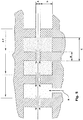
- the supporting structure of stretching chest 1 consists of a sturdy steel base frame 3 on which a series of mutually parallel collars 4 are anchored perpendicular to the longitudinal direction of chest 1.
- the anchoring of collars 4 is preferably carried out through a hinge 5, at one end of each collar, and a lever tie rod 6 at the opposite end.
- the lever tie rod 6, preferably is of the type which provides a safety position (for example of the three, unaligned hinging axis type) to prevent the accidental opening of the tie rod when stretching chamber 1 is brought into pressure.
- hinges 5 and tie rods 6 can be fastened directly to base frame 3 ( fig.
- collars 4 are furthermore made mutually integral by a longitudinal post (not shown) apt to allow the simultaneous lifting/lowering of all collars 4.
- Collars 4 act on the upper portion of stretching chest 1 through contrast rods 8, the position of which can be adjusted through a screw coupling between said contrast rods 8 and collars 4.
- the position of the contact heads of contrast rods 8 with the upper wall of chest 1 can hence be adjusted micrometrically so that the upper wall of chest 1 takes on a perfectly planar shape when resting against such contact heads, when steam stretching chamber 2 is brought to temperature and pressurized.
- the above-said screw coupling is of the mutually-opposite, double-thread type, so as to obtain a very short (0.5 mm) axial displacement of the screw for each full revolution of the same and hence a highly accurate opportunity for fine adjustment.
- the supporting structure of above-described stretching chest 1 has been devised by the Applicant in order to allow the walls of stretching chest 1 to move without restrictions in the different direction of axes x and y following the thermal expansion resulting from the heating of said walls at the operating temperature.
- each of such walls it is preferable for each of such walls to have a single fixed point in a predetermined position and that all the other points of contact have a friction resistance as low as possible in the directions of axes x and y .
- the fixed point of the upper portion of chest 1 is obtained by securely fixing, for example by welding or screw means, the contact head of a single contrast rod 8 to the respective outer wall of the upper portion of chest 1, so that the position of this rod represents the fixed reference point for said portion.
- said rod is the central one of the collar 4 arranged in correspondence of the centre-line of chest 1, so that the fixed reference point coincides with the central point of the upper portion of chest 1, thus minimising the width of the mutual movement between the upper portion of chest 1 and the contact heads of all other contrast rods 8.
- the fixed point of the lower portion of chest 1 is obtained in a fully similar way by using support rods 9 directly fastened to base frame 3 ( fig. 4 ) or to the upper part of crossmembers 7. Also in this case, only one of supporting rods 9, and preferably the one arranged in correspondence of the centre of the outer wall of the lower portion of stretching chest 1, is anchored to said wall, while all the others have a simple chafing contact which does not limit the movement of the lower portion of chest 1 with respect to the thermal expansion it undergoes.
- an insert of hardened steel is inserted and secured in the corresponding portions of chest 1, for example with a threaded coupling.
- Some of such inserts, and preferably the ones arranged in correspondence of the longitudinal axis of said walls of chest 1, can have also guiding grooves provided with lateral shoulders within which a mushroom-shaped end of a contact head of contrast rods 8 or of supporting rods 9 can be housed.
- This particular coupling hence always allows a degree of freedom to the affected portion of the wall of chest 1 along the longitudinal x axis, but does not instead allow a displacement of such wall portion along the crosswise y axis, thus defining that such axes maintain in any case steady directions.
- This solution furthermore allows to make the upper portion of chest 1 integral with collars 4, so that chest 1 may be simply opened by causing collars 4 to rotate around hinges 5, after having unfastened lever tie rods 6.
- the above-described arrangement makes stretching chest 1 an independent unit, which can be easily opened and easily removed from the corresponding supporting structure, thus making very easy and fast both the drawing-in of the tows and the maintenance and/or the replacement of the two portions of chest 1 to adapt them to different processes or to fibres of different materials.
- the inlet of the overheated and pressurized steam into steam stretching chamber 2 is performed in two positions symmetrically arranged with respect to the centre-line of chest 1, through inlet ports 10 formed in the lower wall of chest 1 and the steam is evenly distributed in chamber 2 through a perforated distributor 11.
- the condensation water collects at the opposite ends of chamber 2 and is discharged through outlet ports 12.
- pressure seals are formed capable of imparting a great loss of load to the steam and thus of minimising steam losses through said slits 13.
- the two pressure seals have identical shape, so that the description will be given only for the pressure seal in correspondence of the inlet slit of tows T illustrated in cross-section in fig. 4 and, in an enlarged scale, in the detail of fig. 5 .
- Said pressure seal consists of two opposite plates 14, each one integral with a respective wall of the stretching chest 1, mutually facing at a short distance ranging between 0.3-2.0 mm, preferably of 0.5-1 mm.
- the inner surface of opposite plates 14 is provided with a series of symmetrically opposite, parallel grooves, having a direction perpendicular to the sliding direction of tows T, which hence form a succession of deeper compartments, separated by bottlenecks in correspondence of the non-grooved areas of opposite plates 14.
- the preferred shape for the grooves formed in the inner part of plates 14 is the one illustrated in the drawings, that is a Greek fret-like, right-angle and sharp-edge section; other shapes are of course possible for said grooves even though the one indicated above has proved to be the most effective for guaranteeing a pneumodynamic effect by the outgoing steam sufficient to support in a centred manner tows T in the bottleneck areas and to hence avoid any possible contact of tows T with plates 14.
- the pneumodynamic centring of tows T within the bottleneck areas of the pressure seals is so effective as to allow the replacement of the costly chromium plating or ceramic-coating procedure - which in the prior art is applied to all parts of the apparatus in possible contact with fibres - with a much cheaper Teflon-coating or nickel/coating process which as a matter of fact is used in the present invention exclusively for reducing the frictions in the initial transient phases an hence has a fully satisfactory duration.
- a correct sizing of the grooves formed on the inner wall of plates 14 - having indicated with B the length of the bottleneck areas, with C the pitch of the toothing in a longitudinal direction and with D the depth of the compartments formed by the opposite grooves ( fig. 5 ) - can be obtained maintaining said values within the conditions reported below: 2 / 10 C ⁇ B ⁇ 5 / 10 C 10 A ⁇ C ⁇ 20 A 6 A ⁇ D ⁇ 15 A where A represents, as above, the distance between opposite plates 14.
- travelling tows T are finally preferably treated with a flow rate of overheated water H ( fig. 5 ), possibly charged with a finishing material, pouring said water into one of the innermost compartments of the pressure seal.
- Suction hood 15 is furthermore connected in 16 to a suction fan which maintains a slight depression within hood 15, sufficient for avoiding steam leaks from slit 13, maintaining a slight air flow through slit 13 directed to the inside of suction hood 15.
- the flow rate of such air flow may be adjusted choking inlet/outlet slit 13 through an adjustable-position diaphragm applied externally to said slit.
- Plates 14 extend within chamber 2, so as to be surrounded by the overheated steam inserted into said chamber and be thus maintained at a high temperature. This clever device prevents that within the seals a condensation of the outgoing steam may occur on the walls, which condensation might cause problems to the fibres dripping onto tows T.
- plates 14 are evidently subject to a differential pressure, increasing towards the outer end thereof, since the pressure within the seals gradually decreases, while the one outside the seals (i.e., within chamber 2) is constant. Therefore, to avoid that such differential pressure may in time lead to deformations or deflections of plates 14, such plates are mechanically connected to the adjoining walls of chamber 2 through rigid connecting elements 17.
- steam stretching chamber 2 extends also above suction hood 15, in order to keep also the upper wall of the same warm and hence prevent condensation from forming on such wall, which condensation might drip onto tows T, deteriorating the quality thereof. Still for the purpose of preventing condensation from forming above the entire path of tows T, in the entire upper area of the steam stretching chamber 2 a heating coil 18 is finally arranged, fed with overheated steam, which maintains this area constantly above the dew temperature and hence avoids any problem of condensation forming on the inner wall of the upper portion of the stretching chest 1.
- the present invention also relates to a drawing-in device of the tows which allows to draw-in a broken tow T B without having to interrupt the operation of the stretching apparatus according to the present invention.
- Such accessory device is illustrated in figs. 1 and 7 and comprises a flexible belt of thin steel 22, of 0.15-0.30 mm thickness, arranged along a closed loop path, on 4 or more transmission pulleys, one of said pulleys being associated with manual or motorised driving means.
- One of the branches of loop belt 22 is arranged within the steam stretching chamber 2, in a lateral position with respect to tows T, so as to create no interference with the same.
- broken tow T B is inserted and sucked into a fixed suction unit 20 (discontinuous line --------).
- tow T B is taken from fixed unit 20 and cut.
- the free end of tow T B thus retained is fastened to a hole 21 suitably provided on the steel belt 22 of the drawing-in device (full circle line ⁇ ).
- the drawing-in device is actuated, manually or by a motor, to cause the belt to flow and thus bring the free end of broken tow T B into and beyond the stretching apparatus (cross line ++++++++), while the set of rolls R 1 continues to feed the tow which gathers in a container 23.
- said free end of broken tow T B is unfastened from belt 22 and wound around a capstan 24 which provides to retrieve the entire tow from container 23 tensioning it (empty circle line °°°°°°).
- the operator cuts the broken tow T B off the capstan and fastens it, with the help of a mobile sucking pistol, onto the drawing set of rollers R 2 in the position remained empty, corresponding to the outlet one of tow T B from set of rollers R 1 . If the introduction of tow T B is performed passing below the other evenly moving tows T, broken tow T B , due to the action of the drawing set of rollers R 2 , is quickly brought back into its ordinary operating position, even in case said position lies laterally distant with respect to the position of the drawing-in device, and the operation of the stretching apparatus can continue without interruptions.
- the stretching apparatus of the present invention due to the construction of the stretching chest in two opposite portions which can be easily opened, enormously facilitates the initial drawing-in operations of the tows and, due to the drawing-in device, allows to recover tow breakage situations without interrupting the processing on the remaining tows.
- the damages due to missed production are hence dramatically reduced with respect to the prior art apparatuses wherein any problem, arising even on only one of the side-by-side tows, necessarily required the interruption of the processing on the entire stretching apparatus.
Landscapes
- Engineering & Computer Science (AREA)
- Textile Engineering (AREA)
- Chemical & Material Sciences (AREA)
- Mechanical Engineering (AREA)
- Materials Engineering (AREA)
- Yarns And Mechanical Finishing Of Yarns Or Ropes (AREA)
- Treatment Of Fiber Materials (AREA)
- Chemical Kinetics & Catalysis (AREA)
- General Chemical & Material Sciences (AREA)
- Pressure Vessels And Lids Thereof (AREA)
Applications Claiming Priority (2)
| Application Number | Priority Date | Filing Date | Title |
|---|---|---|---|
| IT000821A ITMI20130821A1 (it) | 2013-05-21 | 2013-05-21 | Apparecchiatura per lo stiro di fibre acriliche in atmosfera di vapore in pressione e dispositivo automatico di incorsamento per detta apparecchiatura. |
| PCT/IB2014/061562 WO2014188341A2 (en) | 2013-05-21 | 2014-05-20 | Apparatus for stretching acrylic fibres in a pressurized steam environment and automatic drawing-in device for said apparatus |
Publications (2)
| Publication Number | Publication Date |
|---|---|
| EP2999811A2 EP2999811A2 (en) | 2016-03-30 |
| EP2999811B1 true EP2999811B1 (en) | 2017-04-19 |
Family
ID=48670710
Family Applications (1)
| Application Number | Title | Priority Date | Filing Date |
|---|---|---|---|
| EP14789869.6A Active EP2999811B1 (en) | 2013-05-21 | 2014-05-20 | Apparatus for stretching acrylic fibers in a pressurized steam environment and automatic fiber drawing-in device for said apparatus |
Country Status (8)
| Country | Link |
|---|---|
| US (1) | US9869041B2 (OSRAM) |
| EP (1) | EP2999811B1 (OSRAM) |
| JP (1) | JP6483091B2 (OSRAM) |
| KR (1) | KR102059715B1 (OSRAM) |
| CN (1) | CN105431581B (OSRAM) |
| IT (1) | ITMI20130821A1 (OSRAM) |
| RU (1) | RU2631621C2 (OSRAM) |
| WO (1) | WO2014188341A2 (OSRAM) |
Families Citing this family (8)
| Publication number | Priority date | Publication date | Assignee | Title |
|---|---|---|---|---|
| RU2682765C1 (ru) * | 2015-06-16 | 2019-03-21 | М.А.Е. С.П.А. | Многоместный плоскотрубчатый аппарат для вытяжки акриловых волокон в паровой окружающей среде под давлением |
| CN107447324A (zh) * | 2017-08-24 | 2017-12-08 | 江苏金斗重工有限公司 | 电加热热牵伸箱 |
| KR102555678B1 (ko) * | 2018-03-27 | 2023-07-17 | 도레이 카부시키가이샤 | 아크릴로니트릴계 섬유 다발의 제조 방법 및 탄소 섬유 다발의 제조 방법 |
| KR102150587B1 (ko) * | 2018-12-14 | 2020-09-01 | 일진에이테크 주식회사 | 실 연신 장치 |
| CN109778328B (zh) * | 2018-12-19 | 2020-08-04 | 四川辉腾科技股份有限公司 | 一种芳纶ⅲ纤维连续式鼓风热处理装置及工艺 |
| CN110411830A (zh) * | 2019-07-26 | 2019-11-05 | 安徽珍瑾服装有限公司 | 一种生物质纤维用拉伸检测装置 |
| CN115530419B (zh) * | 2022-10-12 | 2024-06-25 | 湖北中烟工业有限责任公司 | 一种甘油喷洒装置以及滤嘴成型机 |
| CN118653275B (zh) * | 2024-08-19 | 2024-11-29 | 启东乐欣纺织科技有限公司 | 一种衬布底布的烘箱式定型机 |
Family Cites Families (25)
| Publication number | Priority date | Publication date | Assignee | Title |
|---|---|---|---|---|
| US1914024A (en) * | 1929-05-22 | 1933-06-13 | Maurice M Kasanof | Steaming unit for tentering machines |
| US2520202A (en) * | 1946-01-21 | 1950-08-29 | Celanese Corp | Treatment of filaments, foils, and similar articles |
| US2865112A (en) * | 1955-11-16 | 1958-12-23 | Dow Chemical Co | Sealing orifice for steam tubes and the like |
| US3503100A (en) * | 1966-09-08 | 1970-03-31 | Eastman Kodak Co | Method of processing large denier tow |
| JPS4710803Y1 (OSRAM) * | 1967-09-09 | 1972-04-21 | ||
| US3761977A (en) * | 1971-09-17 | 1973-10-02 | S Rappoport | Process and apparatus for treatment of textile materials |
| US3868215A (en) * | 1973-04-05 | 1975-02-25 | Samcoe Holding Corp | Method of steam processing tubular knit fabric or the like |
| US4059668A (en) * | 1973-11-13 | 1977-11-22 | Monsanto Company | Method of stretching a tow |
| IL49253A (en) * | 1975-05-27 | 1979-09-30 | Monsanto Co | Apparatus for applying steam to a tow |
| US4183151A (en) * | 1977-11-03 | 1980-01-15 | Samcoe Holding Corporation | High production steamer for tubular knitted fabric or the like |
| US4641504A (en) * | 1984-06-12 | 1987-02-10 | Barmag Barmer Maschinenfabrik Ag | Yarn heating chamber |
| US4974431A (en) * | 1989-11-28 | 1990-12-04 | Interface, Inc. | Device for treating materials with steam |
| JP3173669B2 (ja) * | 1992-06-24 | 2001-06-04 | 日本エクスラン工業株式会社 | 合成繊維トウ用連続熱処理機の圧力維持方法 |
| DK1061163T3 (da) * | 1998-02-28 | 2005-11-14 | Ube Nitto Kasei Co | Indretning til at trække trækbart, termoplastisk harpiksmateriale |
| WO2002070808A1 (en) * | 2000-11-14 | 2002-09-12 | Arteva Technologies S.A.R.L. | Improved steam seal for textile production |
| AU2003273907A1 (en) * | 2002-09-26 | 2004-04-23 | Saurer Gmbh And Co. Kg | Method for producing highly stable polypropylene fibres |
| JP4710803B2 (ja) | 2006-11-13 | 2011-06-29 | トヨタ自動車株式会社 | 内燃機関の排気浄化装置 |
| JP5012089B2 (ja) | 2007-03-02 | 2012-08-29 | 東レ株式会社 | 炭素繊維前駆体繊維束およびその製造方法 |
| JP2008240203A (ja) | 2007-03-28 | 2008-10-09 | Toray Ind Inc | スチーム延伸装置および炭素繊維用前駆体糸条の製造方法 |
| JP5249624B2 (ja) | 2008-04-14 | 2013-07-31 | 三菱レイヨン株式会社 | 糸条の加圧スチーム処理装置および加圧スチーム処理方法 |
| CN201952558U (zh) * | 2010-12-03 | 2011-08-31 | 西安航科等离子体科技有限公司 | 用于纤维牵伸的加压水蒸汽牵伸装置 |
| KR101637611B1 (ko) | 2010-12-31 | 2016-07-07 | 코오롱인더스트리 주식회사 | 탄소섬유용 폴리아크릴로니트릴계 전구체 섬유의 제조방법 |
| MX2013009249A (es) | 2011-02-10 | 2013-11-04 | Mitsubishi Rayon Co | Un aparato de tratamiento por vapor a presion de un haz de fibras acrilicas precursoras de fibras de carbono y un metodo para producir un haz de fibras acrilicas. |
| KR101576341B1 (ko) | 2011-03-09 | 2015-12-09 | 미쯔비시 레이온 가부시끼가이샤 | 사조의 가압 스팀 처리 장치와 탄소 섬유 전구체 사조의 제조 방법 |
| WO2014022223A1 (en) * | 2012-07-31 | 2014-02-06 | Tubular Textile Machinery, Inc. | Adjustable width steam box for fabric processing and method of using the same |
-
2013
- 2013-05-21 IT IT000821A patent/ITMI20130821A1/it unknown
-
2014
- 2014-05-20 CN CN201480041105.XA patent/CN105431581B/zh active Active
- 2014-05-20 EP EP14789869.6A patent/EP2999811B1/en active Active
- 2014-05-20 US US14/893,330 patent/US9869041B2/en active Active
- 2014-05-20 RU RU2015154459A patent/RU2631621C2/ru active
- 2014-05-20 KR KR1020157035868A patent/KR102059715B1/ko active Active
- 2014-05-20 JP JP2016514513A patent/JP6483091B2/ja active Active
- 2014-05-20 WO PCT/IB2014/061562 patent/WO2014188341A2/en not_active Ceased
Also Published As
| Publication number | Publication date |
|---|---|
| WO2014188341A3 (en) | 2015-03-26 |
| WO2014188341A2 (en) | 2014-11-27 |
| US9869041B2 (en) | 2018-01-16 |
| EP2999811A2 (en) | 2016-03-30 |
| CN105431581A (zh) | 2016-03-23 |
| RU2015154459A (ru) | 2017-06-26 |
| JP6483091B2 (ja) | 2019-03-13 |
| US20160102421A1 (en) | 2016-04-14 |
| JP2016522864A (ja) | 2016-08-04 |
| ITMI20130821A1 (it) | 2013-08-20 |
| KR20160030108A (ko) | 2016-03-16 |
| KR102059715B1 (ko) | 2019-12-26 |
| CN105431581B (zh) | 2017-08-04 |
| RU2631621C2 (ru) | 2017-09-25 |
Similar Documents
| Publication | Publication Date | Title |
|---|---|---|
| EP2999811B1 (en) | Apparatus for stretching acrylic fibers in a pressurized steam environment and automatic fiber drawing-in device for said apparatus | |
| KR101028962B1 (ko) | 섬유 강화 수지 스트랜드의 제조장치 | |
| DE102013223663B4 (de) | Garnaufnahmevorrichtung | |
| KR101609209B1 (ko) | 열경화성 및 열가소성 프리프레그 선택적 제조시스템 | |
| EP2875945B1 (en) | Stitched carbon fiber base material and wet prepreg using same | |
| US8621722B2 (en) | Method for the continuous production of laid staple fibre fabrics from finitely long reinforcing fibres with aligned fibre orientation | |
| JP7312380B2 (ja) | 熱可塑性樹脂含浸シート状強化繊維束の製造方法 | |
| BR112020007530B1 (pt) | Dispositivo e método para impregnar feixes de fibras com uma massa fundida de polímero | |
| RU132106U1 (ru) | Технологическая линия для изготовления неметаллической арматуры | |
| KR20210116294A (ko) | 화학 섬유의 습식 스피닝을 위한 소형 모듈 | |
| EP3310951B1 (en) | Apparatus for stretching acrylic fibres tows in a pressurised steam environment | |
| JP4038521B2 (ja) | 長繊維強化樹脂ストランドの製造装置 | |
| KR101676729B1 (ko) | 스프레딩 장치 및 그 스프레딩 장치를 포함하는 원사의 스프레딩 시스템 | |
| KR101279328B1 (ko) | 장섬유 강화 열가소성 수지 펠릿의 제조장치 | |
| US8956142B2 (en) | Method and device for producing strand-shaped goods | |
| JP4671859B2 (ja) | 長繊維強化熱可塑性樹脂材料の製造装置及びその製造方法 | |
| RU2742170C1 (ru) | Способ непрерывного изготовления термопластичного армированного пултрузионного профиля | |
| CN217149352U (zh) | 一种具有浸润装置的碳纤维表面镀膜生产设备 | |
| JPH10309756A (ja) | 一方向強化樹脂構造体の製造方法及びその製造装置 | |
| JPH10337786A (ja) | 長繊維強化熱可塑性樹脂シートの製造方法及びその製造装置 | |
| CN119159789A (zh) | 一种纤维带状集束缠绕导丝装置及方法 |
Legal Events
| Date | Code | Title | Description |
|---|---|---|---|
| PUAI | Public reference made under article 153(3) epc to a published international application that has entered the european phase |
Free format text: ORIGINAL CODE: 0009012 |
|
| 17P | Request for examination filed |
Effective date: 20151221 |
|
| AK | Designated contracting states |
Kind code of ref document: A2 Designated state(s): AL AT BE BG CH CY CZ DE DK EE ES FI FR GB GR HR HU IE IS IT LI LT LU LV MC MK MT NL NO PL PT RO RS SE SI SK SM TR |
|
| AX | Request for extension of the european patent |
Extension state: BA ME |
|
| DAX | Request for extension of the european patent (deleted) | ||
| REG | Reference to a national code |
Ref country code: DE Ref legal event code: R079 Ref document number: 602014008907 Country of ref document: DE Free format text: PREVIOUS MAIN CLASS: D02J0001220000 Ipc: D06B0017000000 |
|
| RIC1 | Information provided on ipc code assigned before grant |
Ipc: D02J 13/00 20060101ALI20160930BHEP Ipc: D02J 1/22 20060101ALI20160930BHEP Ipc: D06B 23/14 20060101ALI20160930BHEP Ipc: D06B 23/18 20060101ALI20160930BHEP Ipc: D06B 17/00 20060101AFI20160930BHEP Ipc: D06C 7/00 20060101ALI20160930BHEP Ipc: D06C 3/00 20060101ALI20160930BHEP |
|
| GRAP | Despatch of communication of intention to grant a patent |
Free format text: ORIGINAL CODE: EPIDOSNIGR1 |
|
| INTG | Intention to grant announced |
Effective date: 20161118 |
|
| GRAS | Grant fee paid |
Free format text: ORIGINAL CODE: EPIDOSNIGR3 |
|
| GRAA | (expected) grant |
Free format text: ORIGINAL CODE: 0009210 |
|
| AK | Designated contracting states |
Kind code of ref document: B1 Designated state(s): AL AT BE BG CH CY CZ DE DK EE ES FI FR GB GR HR HU IE IS IT LI LT LU LV MC MK MT NL NO PL PT RO RS SE SI SK SM TR |
|
| REG | Reference to a national code |
Ref country code: GB Ref legal event code: FG4D |
|
| REG | Reference to a national code |
Ref country code: CH Ref legal event code: EP |
|
| REG | Reference to a national code |
Ref country code: FR Ref legal event code: PLFP Year of fee payment: 4 |
|
| REG | Reference to a national code |
Ref country code: AT Ref legal event code: REF Ref document number: 886069 Country of ref document: AT Kind code of ref document: T Effective date: 20170515 |
|
| REG | Reference to a national code |
Ref country code: IE Ref legal event code: FG4D |
|
| REG | Reference to a national code |
Ref country code: DE Ref legal event code: R096 Ref document number: 602014008907 Country of ref document: DE |
|
| REG | Reference to a national code |
Ref country code: NL Ref legal event code: MP Effective date: 20170419 |
|
| REG | Reference to a national code |
Ref country code: LT Ref legal event code: MG4D |
|
| REG | Reference to a national code |
Ref country code: AT Ref legal event code: MK05 Ref document number: 886069 Country of ref document: AT Kind code of ref document: T Effective date: 20170419 |
|
| PG25 | Lapsed in a contracting state [announced via postgrant information from national office to epo] |
Ref country code: NL Free format text: LAPSE BECAUSE OF FAILURE TO SUBMIT A TRANSLATION OF THE DESCRIPTION OR TO PAY THE FEE WITHIN THE PRESCRIBED TIME-LIMIT Effective date: 20170419 |
|
| PG25 | Lapsed in a contracting state [announced via postgrant information from national office to epo] |
Ref country code: HR Free format text: LAPSE BECAUSE OF FAILURE TO SUBMIT A TRANSLATION OF THE DESCRIPTION OR TO PAY THE FEE WITHIN THE PRESCRIBED TIME-LIMIT Effective date: 20170419 Ref country code: ES Free format text: LAPSE BECAUSE OF FAILURE TO SUBMIT A TRANSLATION OF THE DESCRIPTION OR TO PAY THE FEE WITHIN THE PRESCRIBED TIME-LIMIT Effective date: 20170419 Ref country code: LT Free format text: LAPSE BECAUSE OF FAILURE TO SUBMIT A TRANSLATION OF THE DESCRIPTION OR TO PAY THE FEE WITHIN THE PRESCRIBED TIME-LIMIT Effective date: 20170419 Ref country code: NO Free format text: LAPSE BECAUSE OF FAILURE TO SUBMIT A TRANSLATION OF THE DESCRIPTION OR TO PAY THE FEE WITHIN THE PRESCRIBED TIME-LIMIT Effective date: 20170719 Ref country code: FI Free format text: LAPSE BECAUSE OF FAILURE TO SUBMIT A TRANSLATION OF THE DESCRIPTION OR TO PAY THE FEE WITHIN THE PRESCRIBED TIME-LIMIT Effective date: 20170419 Ref country code: GR Free format text: LAPSE BECAUSE OF FAILURE TO SUBMIT A TRANSLATION OF THE DESCRIPTION OR TO PAY THE FEE WITHIN THE PRESCRIBED TIME-LIMIT Effective date: 20170720 Ref country code: AT Free format text: LAPSE BECAUSE OF FAILURE TO SUBMIT A TRANSLATION OF THE DESCRIPTION OR TO PAY THE FEE WITHIN THE PRESCRIBED TIME-LIMIT Effective date: 20170419 |
|
| PG25 | Lapsed in a contracting state [announced via postgrant information from national office to epo] |
Ref country code: SE Free format text: LAPSE BECAUSE OF FAILURE TO SUBMIT A TRANSLATION OF THE DESCRIPTION OR TO PAY THE FEE WITHIN THE PRESCRIBED TIME-LIMIT Effective date: 20170419 Ref country code: PL Free format text: LAPSE BECAUSE OF FAILURE TO SUBMIT A TRANSLATION OF THE DESCRIPTION OR TO PAY THE FEE WITHIN THE PRESCRIBED TIME-LIMIT Effective date: 20170419 Ref country code: IS Free format text: LAPSE BECAUSE OF FAILURE TO SUBMIT A TRANSLATION OF THE DESCRIPTION OR TO PAY THE FEE WITHIN THE PRESCRIBED TIME-LIMIT Effective date: 20170819 Ref country code: LV Free format text: LAPSE BECAUSE OF FAILURE TO SUBMIT A TRANSLATION OF THE DESCRIPTION OR TO PAY THE FEE WITHIN THE PRESCRIBED TIME-LIMIT Effective date: 20170419 Ref country code: BG Free format text: LAPSE BECAUSE OF FAILURE TO SUBMIT A TRANSLATION OF THE DESCRIPTION OR TO PAY THE FEE WITHIN THE PRESCRIBED TIME-LIMIT Effective date: 20170719 Ref country code: RS Free format text: LAPSE BECAUSE OF FAILURE TO SUBMIT A TRANSLATION OF THE DESCRIPTION OR TO PAY THE FEE WITHIN THE PRESCRIBED TIME-LIMIT Effective date: 20170419 |
|
| REG | Reference to a national code |
Ref country code: CH Ref legal event code: PL |
|
| REG | Reference to a national code |
Ref country code: DE Ref legal event code: R097 Ref document number: 602014008907 Country of ref document: DE |
|
| PG25 | Lapsed in a contracting state [announced via postgrant information from national office to epo] |
Ref country code: MC Free format text: LAPSE BECAUSE OF FAILURE TO SUBMIT A TRANSLATION OF THE DESCRIPTION OR TO PAY THE FEE WITHIN THE PRESCRIBED TIME-LIMIT Effective date: 20170419 Ref country code: EE Free format text: LAPSE BECAUSE OF FAILURE TO SUBMIT A TRANSLATION OF THE DESCRIPTION OR TO PAY THE FEE WITHIN THE PRESCRIBED TIME-LIMIT Effective date: 20170419 Ref country code: CZ Free format text: LAPSE BECAUSE OF FAILURE TO SUBMIT A TRANSLATION OF THE DESCRIPTION OR TO PAY THE FEE WITHIN THE PRESCRIBED TIME-LIMIT Effective date: 20170419 Ref country code: DK Free format text: LAPSE BECAUSE OF FAILURE TO SUBMIT A TRANSLATION OF THE DESCRIPTION OR TO PAY THE FEE WITHIN THE PRESCRIBED TIME-LIMIT Effective date: 20170419 Ref country code: RO Free format text: LAPSE BECAUSE OF FAILURE TO SUBMIT A TRANSLATION OF THE DESCRIPTION OR TO PAY THE FEE WITHIN THE PRESCRIBED TIME-LIMIT Effective date: 20170419 Ref country code: SK Free format text: LAPSE BECAUSE OF FAILURE TO SUBMIT A TRANSLATION OF THE DESCRIPTION OR TO PAY THE FEE WITHIN THE PRESCRIBED TIME-LIMIT Effective date: 20170419 |
|
| REG | Reference to a national code |
Ref country code: IE Ref legal event code: MM4A |
|
| PLBE | No opposition filed within time limit |
Free format text: ORIGINAL CODE: 0009261 |
|
| STAA | Information on the status of an ep patent application or granted ep patent |
Free format text: STATUS: NO OPPOSITION FILED WITHIN TIME LIMIT |
|
| PG25 | Lapsed in a contracting state [announced via postgrant information from national office to epo] |
Ref country code: SM Free format text: LAPSE BECAUSE OF FAILURE TO SUBMIT A TRANSLATION OF THE DESCRIPTION OR TO PAY THE FEE WITHIN THE PRESCRIBED TIME-LIMIT Effective date: 20170419 Ref country code: LI Free format text: LAPSE BECAUSE OF NON-PAYMENT OF DUE FEES Effective date: 20170531 Ref country code: CH Free format text: LAPSE BECAUSE OF NON-PAYMENT OF DUE FEES Effective date: 20170531 |
|
| 26N | No opposition filed |
Effective date: 20180122 |
|
| PG25 | Lapsed in a contracting state [announced via postgrant information from national office to epo] |
Ref country code: LU Free format text: LAPSE BECAUSE OF NON-PAYMENT OF DUE FEES Effective date: 20170520 |
|
| REG | Reference to a national code |
Ref country code: BE Ref legal event code: MM Effective date: 20170531 |
|
| PG25 | Lapsed in a contracting state [announced via postgrant information from national office to epo] |
Ref country code: IE Free format text: LAPSE BECAUSE OF NON-PAYMENT OF DUE FEES Effective date: 20170520 |
|
| REG | Reference to a national code |
Ref country code: FR Ref legal event code: PLFP Year of fee payment: 5 |
|
| PG25 | Lapsed in a contracting state [announced via postgrant information from national office to epo] |
Ref country code: SI Free format text: LAPSE BECAUSE OF FAILURE TO SUBMIT A TRANSLATION OF THE DESCRIPTION OR TO PAY THE FEE WITHIN THE PRESCRIBED TIME-LIMIT Effective date: 20170419 |
|
| PG25 | Lapsed in a contracting state [announced via postgrant information from national office to epo] |
Ref country code: BE Free format text: LAPSE BECAUSE OF NON-PAYMENT OF DUE FEES Effective date: 20170531 |
|
| PG25 | Lapsed in a contracting state [announced via postgrant information from national office to epo] |
Ref country code: MT Free format text: LAPSE BECAUSE OF NON-PAYMENT OF DUE FEES Effective date: 20170520 |
|
| PG25 | Lapsed in a contracting state [announced via postgrant information from national office to epo] |
Ref country code: HU Free format text: LAPSE BECAUSE OF FAILURE TO SUBMIT A TRANSLATION OF THE DESCRIPTION OR TO PAY THE FEE WITHIN THE PRESCRIBED TIME-LIMIT; INVALID AB INITIO Effective date: 20140520 |
|
| PG25 | Lapsed in a contracting state [announced via postgrant information from national office to epo] |
Ref country code: CY Free format text: LAPSE BECAUSE OF FAILURE TO SUBMIT A TRANSLATION OF THE DESCRIPTION OR TO PAY THE FEE WITHIN THE PRESCRIBED TIME-LIMIT Effective date: 20170419 |
|
| PG25 | Lapsed in a contracting state [announced via postgrant information from national office to epo] |
Ref country code: MK Free format text: LAPSE BECAUSE OF FAILURE TO SUBMIT A TRANSLATION OF THE DESCRIPTION OR TO PAY THE FEE WITHIN THE PRESCRIBED TIME-LIMIT Effective date: 20170419 |
|
| PG25 | Lapsed in a contracting state [announced via postgrant information from national office to epo] |
Ref country code: TR Free format text: LAPSE BECAUSE OF FAILURE TO SUBMIT A TRANSLATION OF THE DESCRIPTION OR TO PAY THE FEE WITHIN THE PRESCRIBED TIME-LIMIT Effective date: 20170419 |
|
| PG25 | Lapsed in a contracting state [announced via postgrant information from national office to epo] |
Ref country code: PT Free format text: LAPSE BECAUSE OF FAILURE TO SUBMIT A TRANSLATION OF THE DESCRIPTION OR TO PAY THE FEE WITHIN THE PRESCRIBED TIME-LIMIT Effective date: 20170419 |
|
| PG25 | Lapsed in a contracting state [announced via postgrant information from national office to epo] |
Ref country code: AL Free format text: LAPSE BECAUSE OF FAILURE TO SUBMIT A TRANSLATION OF THE DESCRIPTION OR TO PAY THE FEE WITHIN THE PRESCRIBED TIME-LIMIT Effective date: 20170419 |
|
| PGFP | Annual fee paid to national office [announced via postgrant information from national office to epo] |
Ref country code: GB Payment date: 20200507 Year of fee payment: 7 |
|
| GBPC | Gb: european patent ceased through non-payment of renewal fee |
Effective date: 20210520 |
|
| PG25 | Lapsed in a contracting state [announced via postgrant information from national office to epo] |
Ref country code: GB Free format text: LAPSE BECAUSE OF NON-PAYMENT OF DUE FEES Effective date: 20210520 |
|
| P01 | Opt-out of the competence of the unified patent court (upc) registered |
Effective date: 20230520 |
|
| PGFP | Annual fee paid to national office [announced via postgrant information from national office to epo] |
Ref country code: DE Payment date: 20250415 Year of fee payment: 12 |
|
| PGFP | Annual fee paid to national office [announced via postgrant information from national office to epo] |
Ref country code: IT Payment date: 20250416 Year of fee payment: 12 |
|
| PGFP | Annual fee paid to national office [announced via postgrant information from national office to epo] |
Ref country code: FR Payment date: 20250415 Year of fee payment: 12 |