EP2998875A2 - Expressionsverarbeitungsvorrichtung, compute-server und aufzeichnungsmedium mit darauf gespeichertem programm zur expressionsverarbeitung - Google Patents
Expressionsverarbeitungsvorrichtung, compute-server und aufzeichnungsmedium mit darauf gespeichertem programm zur expressionsverarbeitung Download PDFInfo
- Publication number
- EP2998875A2 EP2998875A2 EP15185876.8A EP15185876A EP2998875A2 EP 2998875 A2 EP2998875 A2 EP 2998875A2 EP 15185876 A EP15185876 A EP 15185876A EP 2998875 A2 EP2998875 A2 EP 2998875A2
- Authority
- EP
- European Patent Office
- Prior art keywords
- expression
- received
- variables
- setting data
- variable values
- Prior art date
- Legal status (The legal status is an assumption and is not a legal conclusion. Google has not performed a legal analysis and makes no representation as to the accuracy of the status listed.)
- Withdrawn
Links
Images










Classifications
-
- G—PHYSICS
- G06—COMPUTING OR CALCULATING; COUNTING
- G06F—ELECTRIC DIGITAL DATA PROCESSING
- G06F15/00—Digital computers in general; Data processing equipment in general
- G06F15/02—Digital computers in general; Data processing equipment in general manually operated with input through keyboard and computation using a built-in program, e.g. pocket calculators
- G06F15/0225—User interface arrangements, e.g. keyboard, display; Interfaces to other computer systems
-
- G—PHYSICS
- G06—COMPUTING OR CALCULATING; COUNTING
- G06F—ELECTRIC DIGITAL DATA PROCESSING
- G06F17/00—Digital computing or data processing equipment or methods, specially adapted for specific functions
- G06F17/10—Complex mathematical operations
- G06F17/16—Matrix or vector computation, e.g. matrix-matrix or matrix-vector multiplication, matrix factorization
Definitions
- the present invention relates to an expression processing device, an expression processing method, a compute server, and a recording medium having an expression processing program recorded thereon.
- JP-A-2011-76540 proposes a technology for converting a text input by a text input display device into a two-dimensional code such as a QR code (a trademark) and displaying the two-dimensional code such that it is possible to photograph the two-dimensional code with a camera of another device and convert the two-dimensional code into the text and use the text in the corresponding device.
- a two-dimensional code such as a QR code (a trademark)
- a technology for converting an input expression into a two-dimensional code, and photographing the two-dimensional code with a camera of a communication device such as a smart phone like, in JP-A-2011-76540 , and calculating the expression in the corresponding communication device, or accessing a compute server to calculate the expression from the corresponding communication device can be considered.
- the expression processing device just converts an input expression into a two-dimensional code like in JP-A-2011-76540
- the expression may be insufficient as information for appropriately calculating the corresponding expression. That is, some expressions need related data essential for calculating those expressions, such as settings and variables essential for calculating those expressions.
- the present invention was made in view of those problems, and an object of the present invention is to provide an expression processing device which can output an input expression such that it is possible to calculate the expression in a communication device or a compute server, a compute server which calculates an expression output from the corresponding expression processing device, and so on.
- An expression processing device of the present invention includes an input unit, a display and a processor.
- the processor is configured to perform following processes: inputting an expression in response to a user's operation on the input unit; detecting a plurality of variables included in the expression input by the input unit, among the plurality of variables which are usable in expressions; and outputting the input expression and variable values associated with the detected variables.
- FIGS. 1A and 1B a system which is composed of a scientific calculator 10 according to a first embodiment of an expression processing device of the present invention, a communication device E, such as a smart phone, having a camera for photographing a two-dimensional code such as a QR code displayed on the scientific calculator 10, a compute server 20 according to the first embodiment of the present invention which the corresponding communication device E with the camera can access through a communication network N such as the Internet according to the content of the photographed two-dimensional code, and a communication device E which receives the calculation result of the corresponding compute server 20 through the communication network N and displays the calculation result, as shown in FIGS. 1A and 1B will be described. Also, FIG.
- the communication device E is not limited to a smart phone, and can be configured as a PDA (personal digital assistant), a tablet PC, a laptop PC (personal computer), etc.
- the scientific calculator 10 is configured in a small size due to the necessity of portability such that a user can sufficiency grip it with one hand and operate it with one hand.
- a key input unit 11 and a display output unit 12 are provided on the front surface of the main body of the scientific calculator 10.
- the key input unit 11 includes a numerical-value/operation-symbol key group 111 for inputting numbers or expressions, or instructing calculation execution, an arithmeticfunction/function key group 112 for inputting various functions or starting a memory function, a mode setting key group 113 for displaying a menu screen of various operating modes or instructing setting of an operating mode, a cursor key 114 for performing an operation to move a cursor displayed on the display output unit 12, an operation to select a data item, etc.
- a numerical-value/operation-symbol key group 111 for inputting numbers or expressions, or instructing calculation execution
- an arithmeticfunction/function key group 112 for inputting various functions or starting a memory function
- a mode setting key group 113 for displaying a menu screen of various operating modes or instructing setting of an operating mode
- a cursor key 114 for performing an operation to move a cursor displayed on the display output unit 12, an operation to select a data item, etc.
- an "x -1 " (x to the negative one power; the reciprocal of x) key, a " ⁇ " (root) key, a “ ⁇ / ⁇ ” (fraction) key, a "sin” (sine) key, an "M+” (memory plus) key, an "OPTN” (option) key, a "RCL” (memory call) key, and so on are arranged.
- mode setting key group 113 As the mode setting key group 113, a "MODE” (mode) key, a “SHIFT” (shift) key, an “ALPHA” (alphabet) key, an “ON” (power-on) key, and so on are arranged.
- each key of the numerical-value/operation-symbol key group 111 and the arithmetic-function/function key group 112 is configured so as to be able to act as a key for a function written above the corresponding key, not a function written on the corresponding key, if the corresponding key and the "SHIFT" key are operated (pressed) at the same time.
- a simultaneous operation on the "SHIFT" key and the "AC” key (This will be hereinafter referred to as a "SHIFT"+”AC” key. The same applies hereinafter) becomes an “OFF" (power-off) key.
- a “SHIFT"+"OPTN" key becomes a "QR" (QR) key
- a "SHIFT"+”RCL” key becomes a "STO" (memory registration) key
- the display output unit 12 is composed of a dot matrix type liquid crystal display unit.
- FIG. 2 is a block diagram illustrating the configuration of an electronic circuit of the scientific calculator 10.
- the electronic circuit of the scientific calculator 10 includes a CPU 13 which is a computer (or a processor), a memory 14, and a recording-medium reading unit 15, in addition to the key input unit 11 and the display output unit 12. Also, as shown by a broken line in FIG. 2 , the electronic circuit may include a wireless communication unit 16.
- the CPU 13 controls the operation of each unit of the circuit according to an expression computation process program 141 stored in the memory 14, thereby executing various calculation processes according to key input signals from the key input unit 11.
- the expression computation process program 141 may be stored in advance in the memory 14, or may be loaded from an external recording medium M such as a memory card into the memory 14 through the recording-medium reading unit 15.
- the expression computation process program 141 is configured such that a user cannot rewrite the corresponding program by operating the key input unit 11.
- a unique ID 142 is also stored.
- the unique ID 142 is an ID unique to each scientific calculator 10.
- an setting data memory 144 in order to store data which the user can rewrite, besides such information which the user cannot rewrite, an setting data memory 144, a variable value memory 145, an execution function memory 146, an expression data memory 147, an other-data memory 148, a work area 149, and so on are ensured.
- setting data memory 144 setting data related to various calculation display modes which are set according to an operation on a "SHIFT"+"MODE” key of the key input unit 11 is stored.
- calculation display mode setting data setting data of various calculation display modes such as display modes "1: LineIO (one line display) MODE” and “2: MthIO (textbook display) MODE", angle calculation modes "3: deg (degree) MODE”, “4: rad (radian) MODE”, and “5: gra (grade) MODE”, and rounding calculation modes "6: Fix MODE (in which digits after a decimal point is fixed)", “7: Sci MODE (in which the number of significant digits is designated)”, and “8: Norm MODE (in which rounding is not executed)” are stored.
- a calculation mode such as a function-table function, set according to an operation on a "MODE" key of the key input unit 11 is stored.
- the expression data memory 147 data on key codes input by keys of the key input unit 11 are subsequently input and data on an expression configured thereby is stored.
- the numeric keys are stored as codes representing numbers
- the function keys such as the "sin” key are stored as codes representing the corresponding functions
- the operation symbol keys such as the "+”, "-", " ⁇ ", and " ⁇ ” keys are stored as codes representing the corresponding operation symbols.
- calculation ranges are stored.
- a calculation range includes an initial value, a final value, and a step.
- a variety of data which are input to or output from the CPU 13 according to the expression computation process program 141 is temporarily stored if necessary. For example, settings and variables essential for expression calculation and extracted in a manner to be described in detail below are stored.
- the wireless communication unit 16 has a function of performing wireless communication with the external communication device E or the like by Bluetooth (a trademark), infrared communication, or the like.
- the CPU 13 of the scientific calculator 10 configured as described above controls the operations of the individual units of the circuit according to commands described in the expression computation process program 141 such that software and hardware operate in cooperation with each other, thereby implementing a display control function of converting the address of the compute server 20, the unique ID of the corresponding scientific calculator 10, a function type (for example, the function-table function) input from the key input unit 11, function-based calculation data (for example, a function expression and a calculation range), extraction data, and the other data (for example, setting data) into a two-dimensional code (in the present embodiment, a QR code) and displaying the two-dimensional code by the display output unit 12, as will be described in the following operation description.
- a function type for example, the function-table function
- function-based calculation data for example, a function expression and a calculation range
- extraction data for example, setting data
- other data for example, setting data
- the communication device E with the camera photographs the QR code displayed on the display output unit 12 of the scientific calculator 10, and transmits the content (QR data) of the photographed QR code to the compute server 20 through the communication network N according to the QR data.
- FIG. 3 is a block diagram illustrating the configuration of an electronic circuit of the compute server 20.
- the electronic circuit of the compute server 20 includes a CPU 21 which is a computer, a memory 22, a recording medium 23, a recording-medium reading unit 24, and a communication unit 25. Also, as shown by broken lines in FIG 3 , the electronic circuit may include a key input unit 26 or a display output unit 27.
- the CPU 21 controls the operations of the individual units of the circuit according to a server control program 221 stored in the memory 22, thereby executing various calculation processes according QR data received from the communication device E with the camera by the communication unit 25.
- the server control program may be stored in advance in the memory 22, or may be loaded from the recording medium 23 into the memory 22 through the recording-medium reading unit 24, or may be downloaded from a Web server on the communication network N into the memory 22 through the communication unit 25.
- the server control program 221 is stored, and a reception QR data memory 222 for individually storing QR data items received through the communication unit 25 are ensured.
- the server control program 221 has a function of performing a setting operation or a maintenance operation according to a setting operation, a maintenance operation, or the like on the key input unit 26 by an operator of the corresponding compute server 20, a function of displaying the intermediate progress or result of an operation of the server control program on the display output unit 27, and so on.
- the CPU 21 of the compute server 20 configured as described above controls the operations of the individual units of the circuit according to commands described in the server control program 221 such that software and hardware operate in cooperation with each other, thereby implementing a server process function of calculating an expression based on reception QR data and transmitting the result of the calculation to the communication device E with the camera which is the transmission source of the reception QR data, as will be described in the following operation description.
- the reception QR data includes data includes information for specifying another communication device as a calculation result transmission destination, or a transmission destination is specified in advance in association with the unique ID of the scientific calculator 10, it is possible to transmit the calculation result to a corresponding device other than the communication device E with the camera which is the transmission source.
- the communication device E with the camera receives the calculation result from the compute server 20 through the communication network N, it can display the calculation result on its display output unit ED, or can project the calculation result by connecting a projector P to the corresponding communication device E with the camera.
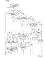
- the CPU 31 controls the display output unit 12 such that the display output unit displays a change screen for changing and setting a plurality of types of setting data relative to expression display calculation.
- the CPU 13 changes the content of the setting data memory 144 of the memory 14 to modes set by user's operations on the key input unit 11 (number inputs using numeric keys). Specifically, if the user presses a numeric key "4", in STEP S105, the angle mode content of the setting data memory 144 of the memory 14 is changed to the radian mode and the changed mode is set.
- the CPU 13 receives an input of a variable value for a variable designated by a user's input operation on the key input unit 11 in STEP S106, and sets the input variable value in the variable value memory 145 for the designated variable in the memory 14 in STEP S107. Thereafter, the CPU 13 returns the process to STEP S101 described above.
- the CPU 13 determines whether the "QR" key, that is, the "SHIFT"+”OPTN" key of the key input unit 11 has been pressed. In a case of determining that the "QR" key has been pressed, the CPU 13 advances the process to STEP S113 to be described below.
- the CPU 31 displays "End?" for inputting the final value on the display output unit 12, thereby prompting the user to input the final value.
- the CPU 31 displays "Step?" for inputting the increment on the display output unit 12, thereby prompting the user to input the increment.
- "1" is registered as the step.
- the CPU 13 calculates a function table, based on the function expressions stored in the expression data memory 147 of the memory 14, the calculation range stored in the other-data memory 148, and the variables stored in the variable value memory 145, and displays the result of the calculation on the display output unit 12 according to the set modes stored in the setting data memory 144.
- the CPU 13 determines whether the "QR" key, that is, the "SHIFT"+”OPTN" key of the key input unit 11 has been pressed. In a case of determining that the "QR" key has been pressed, the CPU 13 advances the process to STEP S113 to be described below. In contrast with this, in a case of determining that the "QR" key has not been pressed, the CPU 13 returns the process to STEP S101 described above.
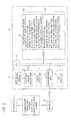
- FIG. 6A shows a flow chart of the necessary-information detecting process.
- the CPU 13 determines whether there is any variable in the input expressions stored in the expression data memory 147 of the memory 14. In a case of determining that there is no variable, in STEP S113B, the CPU 13 determines whether any trigonometric function is included in the input expressions. In a case of determining that any trigonometric function is not included, the CPU 13 returns the process to the upper routine.
- the CPU 13 extracts the values for the variables of the input expressions, for example, "1", "4", and "3", from the variable value memory 145 of the memory 14, and stores the extracted data as extraction data in the work area 149 of the memory 14. Thereafter, the CPU 13 advances the process to STEP S113B as described above.
- the CPU 13 extracts a set angle mode (the deg mode, the rad mode, or the gra mode) from the setting data memory 144 of the memory 14, and stores the extracted data as extraction data in the work area 149 of the memory 14. Thereafter, the CPU 13 returns the process to the upper routine.
- a set angle mode the deg mode, the rad mode, or the gra mode
- the CPU 13 returns the process to the upper routine.
- rounding mode setting data for setting whether to round the decimal is required.
- the rounding mode setting data may also be stored as extraction data in the work area 149.
- individual setting data items of the setting data memory 144 may be collectively stored as extraction data in the work area 149.
- FIG. 7 An example in which a trigonometric function is included in the function expressions is shown in FIG. 7 .
- step113A described above it is determined that there is no variable; however, in step113B described above, it is determined that a trigonometric function is included. Therefore, for example, if it is assumed that the deg mode has been set in STEP S105 described above, in STEP S113D, the deg mode which is the set angle mode is extracted from the setting data memory 144 of the memory 14, and is stored as extraction data in the work area 149 of the memory 14.
- the CPU 13 converts the address of the compute server 20, the unique ID of the corresponding scientific calculator 10 stored in a unique ID memory 142 of the memory 14, the function type of the execution function (for example, "function-table function") stored in execution function memory 146, the function-based calculation data (for example, the function expressions stored in the expression data memory 147 and the calculation range stored in the other-data memory 148), the extraction data stored in the work area 149 (for example, the angle mode extracted from the setting data memory 144, and the variable values extracted from the variable value memory 145), and the others, into a QR code, and displays the QR code on the display output unit 12.
- the function type of the execution function for example, "function-table function”
- the function-based calculation data for example, the function expressions stored in the expression data memory 147 and the calculation range stored in the other-data memory 148
- the extraction data stored in the work area 149 for example, the angle mode extracted from the setting data memory 144, and the variable values extracted from the variable value memory 145
- the QR code is displayed on the display output unit 12. Also, the content of the QR code of Part (F) of FIG. 5 is as shown in Part (G) of FIG. 5 . Also, the content of the QR code of Part (F) of FIG. 7 is as shown in Part (G) of FIG. 7 .
- the CPU 13 determines whether there is a function expression re-input. In a case of determining that there is no re-input, the CPU 13 returns the process to STEP S101 described above.
- the CPU 13 in a case of determining that there is a re-input, the CPU 13 returns the process to STEP S108 described above. Then, the CPU 13 receives an input of a new function expression in the above described manner. In a case where changing of the calculation result is not required with respect to the new function expression, the CPU 13 determines in STEP S109 described above that the "QR" key, that is, the "SHIFT"+”OPTN” key has been pressed, and advances the process to STEP S113 described above.
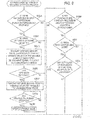
- the CPU 21 of the compute server 20 determines whether to perform a QR data process. In a case of determining to perform another process without performing the QR data process, the CPU 21 advances the process to another process.
- the CPU 21 waits for the communication unit 25 to receive QR data according to a QR operation of the communication device E with the camera. That is, if the scientific calculator 10 displays the QR code on the display output unit 12 by the above described display control process, and that QR code is photographed by the electronic device E with the camera, the content (QR data) of that QR code is decoded, whereby access to the address of the compute server 20 becomes possible. Thereafter, automatically or in response to a user's operation on the electronic device E with the camera, the electronic device E with the camera transmits the QR data to the compute server 20 having the above described address, through the communication network N. In STEP S202, the compute server 20 waits for reception of QR data from the electronic device E with the camera.
- the CPU 21 saves the reception QR data, that is, the unique ID of the scientific calculator 10, the function type (for example, the function-table function), the function-based calculation data (for example, the function expressions and the calculation range), the extraction data (for example, the angle mode and the variable values), and the other data, in the reception QR data memory 222 of the memory 22. Subsequently, in STEP S204, using the function expressions and the extraction data of the saved QR data, the CPU 21 performs a process according to the function type.
- the function type for example, the function-table function
- the function-based calculation data for example, the function expressions and the calculation range
- the extraction data for example, the angle mode and the variable values
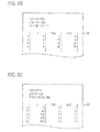
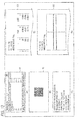
- the CPU 21 performs a calculation with respect to the calculation range, and transmits a table which is the result of the calculation, to the electronic device E with the camera which is the transmission source, through the communication network N by the communication unit 25. Therefore, the electronic device E with the camera having photographed the QR code displayed on the display output unit 12 of the scientific calculator 10 can receive the table which is the calculation result, and display the table on its display output unit ED as shown in FIG. 6B or 6C . Also, FIG. 6B shows a result calculated from the QR data of Part (G) of FIG. 5 , and FIG. 6C shows a result calculated from the QR data of Part (G) of FIG. 7 .
- FIG. 9 shows a flow chart of the expression/detection-data matching checking process.
- the CPU 21 first determines whether there is any variable in the input expressions of the reception QR data stored in the reception QR data memory 222 of the memory 22.
- the input expressions include the function expressions, the initial values, the final values, and the step values (STEP S205A).
- STEP S205B the CPU 21 determines whether any trigonometric function is included in the input expressions. In a case of determining that any trigonometric function is not included, the CPU 21 returns the process to the upper routine.
- the CPU 21 determines whether there is a variable whose value is "0" in the extraction data of the QR data stored in the reception QR data memory 222. In a case of determining that there is no variable whose value is "0" like the QR data of Part (G) of FIG. 5 , the CPU 21 advances the process to STEP S205B described above.
- the CPU 21 determines that the result of the process of STEP S204 described above is erroneous or the corresponding process was impossible. Therefore, for example, if the variable whose value is "0" is the variable A, in STEP S205D, the CPU 21 transmits a message such as "THERE IS A POSSIBILITY THAT ANY VARIABLE VALUE FOR THE VARIABLE A HAS NOT BEEN INPUT. DO YOU WANT TO INPUT? Yes/No" to the communication device E with the camera which is the transmission source, through the communication network N by the communication unit 25.
- the CPU 21 determines whether "Yes” has been received from the communication device E with the camera by the communication unit 25. In a case of determining that "Yes” has not been received, that is, "No" has been received, the CPU 21 advances the process to STEP S205B described above.
- the CPU 21 transmits a message such as "INPUT A VARIABLE VALUE FOR VARIABLE A.” to the communication device E with the camera which is the transmission source, through the communication network N by the communication unit 25. If receiving this message, the communication device E with the camera outputs this message as an alert display on the display output unit ED. Then, the user can confirm the message, and input a required variable value on the communication device E with the camera, and perform an operation for transmitting the input variable value to the compute server 20.
- a message such as "INPUT A VARIABLE VALUE FOR VARIABLE A.”
- the CPU 21 waits for a variable value to be received from the communication device E with the camera by the communication unit 25. If a variable value is received, in STEP S205H, the CPU 21 writes the received variable value in the corresponding reception QR data memory 222 of the memory 22, thereby updating the reception QR data. Thereafter, the CPU 21 advances the process to STEP S205B described above.
- the CPU 21 determines whether the angle mode represented by the extraction data of the reception QR data stored in the reception QR data memory 222 is the deg mode. In a case of determining that the angle mode is the deg mode, the CPU 21 determines whether the set value of the argument of the functions is a multiple of 15 (degrees).
- the set value of the argument of the functions includes not only a set value directly input as the argument in the functions but also a set value for the argument which is calculated by the input expressions (the function expressions, the initial values, the final values, and the step values) during execution of the calculation of each step (STEP S205J).
- the CPU 21 determines that the set value is a multiple of 15 (degrees)
- the CPU 21 determines that the result of the process of STEP S204 described above is erroneous or the corresponding process was impossible, and advances the process to STEP S205N to be described below.
- the CPU 21 determines whether the angle mode is the radian (Rad) mode. In a case of determining that the angle mode is the radian mode, in STEP S205L, the CPU 21 determines whether the set value of the argument of the functions is a multiple of ⁇ /12 (radians). In a case of determining that the set value of the argument of the functions is a multiple of ⁇ /12 (radians), the CPU 21 returns the process to the upper routine.
- the CPU 21 determines that the result of the process of STEP S204 described above is erroneous or the corresponding process was impossible, and advances the process to STEP S205N to be described below.
- the CPU 21 determines that the angle mode is the grade (Grad) mode, and determines whether the set value of the argument of the functions is a multiple of 50/3 (grades), in STEP S205M. In a case of determining that the set value of the argument is a multiple of 50/3 (grades), the CPU 21 returns the process to the upper routine. In contrast with this, in a case of determining that the set value of the argument is not a multiple of 50/3 (grades), the CPU 21 determines that the result of the process of STEP S204 described above is erroneous or the corresponding process was impossible, and advances the process to STEP S205N to be described below.
- the CPU 21 determines that the result of the process of STEP S204 described above is erroneous or the corresponding process was impossible, and advances the process to STEP S205N to be described below.
- the CPU 21 transmits a correction screen such as "THERE IS A POSSIBILITY THAT (ANGLE MODE) SETTING IS ERRONEOUS.
- ODEG ORAD OGRA the current angle mode set value is represented by a black circle, not a white circle
- QR data as shown in Part (G) of FIG. 10 is stored in the reception QR data memory 222 of the memory 22 of the compute server 20. Thereafter, if the process of STEP S204 is performed according to the reception QR data, on the display output unit ED of the communication device E with the camera which is the transmission source, a table as shown in Part (A) of FIG. 11 is displayed as the calculation result.
- the correction screen is transmitted to the communication device E with the camera such that an alert display AL as shown in Part (A) of FIG. 11 can be displayed on the display output unit ED of the communication device E.
- the user If confirming this alert display AL, the user corrects the setting to a correct angle mode as shown in Part (B) of FIG. 11 , on the communication device E with the camera, and performs an operation to transmit the correct set value to the compute server 20.
- the CPU 21 of the compute server 20 waits for a set value to be received from the communication device E with the camera by the communication unit 25. If a set value is received, in STEP S205P, the CPU 21 updates the angle mode of the corresponding reception QR data memory 222 of the memory 22 with the received set value. Thereafter, the CPU 21 returns the process to the upper routine.
- the CPU 21 determines whether the data of the reception QR data memory 222 of the memory has been updated. In a case of determining that the data has not been updated, the CPU 21 finishes the QR data process and returns the process to STEP S201 described above.
- the CPU 21 performs a process according to the function type. For example, in a case of the function-table function, the CPU 21 performs a calculation again with respect to the calculation range, and re-transmits a table which is the result of the calculation, to the electronic device E with the camera which is the transmission source, through the communication network N by the communication unit 25. Therefore, the electronic device E with the camera having received the variable value or having corrected the set value can receive the table re-transmitted as the calculation result, and display the table on the display output unit ED, for example, as shown in Part (C) of FIG 11 . Thereafter, the CPU 21 finishes the QR data process, and returns the process to STEP S201 described above.
- the function of the compute server 20 can be provided in an application form which can be implemented in the communication device E with the camera, for example, a smart phone.
- variable values are stored in the variable value memory 145 with respect to a plurality of variables which can be included in expressions (which are usable in expressions), respectively, and expressions are input according to user's operations on the key input unit 11, and the CPU 13 detects variables included in the input expressions, from the variable values stored in the variable value memory 145, and outputs the input expressions and the variable values of the detected variables to the outside by the display output unit 12.
- the CPU 13 sets a variable value for any one variable stored in the variable value memory 145, according to a user's operation.
- the scientific calculator 10 includes the setting data memory 144 retaining a plurality of types of individual setting data items relative to expression calculation display, and the CPU 13 extracts one or more of the plurality of types of individual setting data items stored in the setting data memory 144, as setting data essential for expression calculation. Then, the CPU 13 outputs the input expressions, the variable values of the detected variables, and one of more setting data items extracted from the plurality of types of individual setting data items, by the display output unit 12.
- the CPU 13 extracts angle mode setting data relative to the calculation of the trigonometric function of the corresponding expressions, as setting data essential for calculating the expressions.
- the compute server 20 receives the expressions together with the variable values for the variables included in the expressions or the setting data essential for calculating the expressions, output from the scientific calculator 10 which is the expression processing device to the outside, by the communication unit 25, and the CPU 21 calculates the expressions based on the received expressions, the received variable values for the variables included in the expressions or the received setting data essential for calculating the expressions, and transmits the calculation result by the communication unit 25. Also, in a case where the received expressions do not match with the received variable values for the variables included in the expressions or the received setting data essential for calculating the expressions, the CPU 21 transmits information representing that they do not match with each other, from the communication unit 25. Therefore, in the case where the expressions do not match with the variable values for the variables included in the expressions or the setting data essential for calculating the expressions, it is possible to receive corrected variable values or setting data by the communication unit 25.
- the communication unit 25 receives the data of the two-dimensional code from the communication device E.
- the CPU 21 calculates the expressions based on the received expressions and the received corrected variable values or setting data, and re-transmits the calculation result by the communication unit 25.
- outputting of the input expressions and the detected setting data or variable values to the outside is not limited to display of the display output unit 12, and may be wirelessly performed by the wireless communication unit 16 as shown by the broken line in FIG. 2 .
- the communication device E with the camera receives the expressions and the setting data or the variable values output to the outside, by a built-in wireless communication unit (not shown), and transmits them to the compute server 20 through the communication network N.
- the scientific calculator 10 which is the expression processing device
- a scientific calculator called a graphing calculator and configured to be able to display a graph of a calculation result.
- the second embodiment is an example of a case where the present invention has been applied to such a graphing calculator.
- the configuration of an electronic circuit of the graphing calculator is similar to that of the scientific calculator 10 of the first embodiment shown in FIG. 2 .
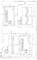
- the angle mode has been set to the radian (Rad) mode. If the compute server 20 performs the calculation process of STEP S204 described above based on that QR data, the electronic device E with the camera displays a table which is the calculation result, on the display output unit ED, as shown in Part (D) of FIG. 12 .
- the CPU 21 determines whether a display switching instruction has been received from the communication device E with the camera by the communication unit 25. In a case of determining that a display switching instruction has not been received, the CPU 21 advances the process to STEP S205 described above.
- the CPU 21 performs a process according to the function type. That is, in STEP S204 described above, since the calculation is performed with the steps represented by the QR data, only discrete calculation results are obtained. Therefore, it is impossible to perform graph display. For this reason, the CPU 21 performs the calculation with a smaller step again, thereby obtaining a calculation result for graph display, and generates graph data from the calculation result, and transmits the graph data to the electronic device E with the camera which is the transmission source, through the communication network N by the communication unit 25. Therefore, the electronic device E with the camera having photographed the QR code displayed on the display output unit 12 of the graphing calculator can receive the graph data which is the calculation result, and display a graph on the display output unit ED as shown in Part (E) of FIG. 12 .
- a correction screen is transmitted to the communication device E with the camera, and an alert display AL as shown in Part (A) of FIG. 13 is displayed on the display output unit ED of the communication device E. If the user confirms that alert display AL, and user corrects the setting to a correct angle mode on the communication device E with the camera, as shown in Part (B) of FIG.
- the CPU 21 updates the angle mode of the corresponding reception QR data memory 222 of the memory 22 with the received set value, in STEP S205P described above, and performs a process according to the function type, using the function expressions and extraction data of the updated QR data. That is, the CPU 21 performs a re-calculation, thereby obtaining graph data as the calculation result, and re-transmits the calculation result to the electronic device E with the camera which the transmission source, through the communication network N by the communication unit 25. Therefore, the electronic device E with the camera can receive the graph data re-transmitted as the calculation result, and display the calculation result on the display output unit ED, for example, as shown in Part (C) of FIG. 13 .
- the CPU 13 extracts the value for the variable included in the input expressions, and saves the extraction data in the work area in STEP S113C, and converts the input expressions together with the values which are extraction data for the variable included in the input expressions, into a QR code, and displays the QR code in STEP S114.
- variable A or B has one numerical value.
- a variable has a vector or a matrix composed of a plurality of numerical values, similarly, it is possible to implement the present invention.
- the following modification represents a case where the variable A is a matrix.
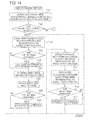
- FIG. 14 is a flow chart illustrating a display control process (the modification) of the scientific calculator.
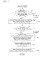
- FIG. 15 is a flow chart illustrating a server process (a matrix mode) of the compute server 20.
- FIG. 16 is a view illustrating a display operation according to a user's operation in the matrix mode according to the display control process of the scientific calculator.
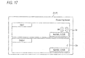
- FIG. 17 is a view illustrating image data of matrix calculation reference information generated according to the server process of the compute server 20 based on barcode content data in the matrix mode of the scientific calculator 10.
- calculation function list menu MF of the present modification eight calculation functions ([1] FOUR-BASIC-OPERATION FUNCTION, [2] COMPLEX NUMBER CALCULATION FUNCTION, [3] N-ARY CALCULATION FUNCTION, [4] MATRIX CALCULATION FUNCTION, [5] VECTOR CALCULATION FUNCTION, [6] STATISTIC CALCULATION FUNCTION, [7] FUNCTION EXPRESSION TABLE CALCULATION FUNCTION, and [8] EQUATION CALCULATION FUNCTION) are displayed so as to be selectable.
- the operation mode of the corresponding scientific calculator 10 is set to the matrix mode, and a matrix name list menu Ma for inputting matrix element data is displayed on the display output unit 12.
- a matrix name (here, "1: MatA") desired by the user is designated in the matrix name list menu Ma in STEP T106 as shown in Part (D) of FIG. 16 , in STEP T107, a matrix size selection menu Mb is displayed on the display output unit 12.
- a desired matrix size here "5: 2 ⁇ 2" is designated in the matrix size selection menu Mb with respect to the matrix name "MatA" in STEP T110 as shown in Part (F) of FIG 16 , in STEP T111, an element data input screen Ga corresponding to the designated matrix size is displayed.
- the CPU 21 determines that barcode content data (QR data) attributable to a QR operation has been received ("Yes" in STEP T301).
- image data which is matrix calculation reference information generated by vertically disposing the generated Input screen Gi and the generated Output screen Go is transmitted to the mail address of the communication device E with the camera of the student or the teacher which is the transmission source of the received barcode content data (QR data).
- the image data Gi/Go of the matrix calculation expression (after replacement with the element data) having been calculated in the scientific calculator 10 of the teacher and the calculation result are displayed as the matrix calculation reference information as shown in FIG. 17 . Thereafter, if the corresponding matrix calculation reference information Gi/Go is magnified and projected by the projector P, everyone of the class of the corresponding student or teacher can learn while confirming the content of the corresponding calculation.
- the matrix calculation function in the matrix mode of the scientific calculator 10 is performed in the same manner as that of the vector calculation function according to a vector mode, and thus a detailed description of the corresponding vector calculation function is omitted.
- the function of the compute server 20 may be provided in an application form which can be implemented in the communication device E with the camera, for example, a smart phone.
- the method of each process of the scientific calculator 10 and the graphing calculator described in each embodiment described above that is, the method of each of various processes such as the display control process shown in the flow chart of FIG. 4 and the necessary-information detecting process shown in the flow chart of FIG. 6A can be stored, as a program which can be executable in any computer, in the external recording medium M such as a memory card (such as a ROM card or a RAM card), a magnetic disk (such as a floppy (a trademark) disk or a hard disk), an optical disk (such as a CD-ROM or a DVD), or a semiconductor memory to be distributed.
- the external recording medium M such as a memory card (such as a ROM card or a RAM card), a magnetic disk (such as a floppy (a trademark) disk or a hard disk), an optical disk (such as a CD-ROM or a DVD), or a semiconductor memory to be distributed.
- the method of each process of the compute server 20 described in each embodiment described above that is, the method of each of various processes such as the server process shown in the flow chart of FIG. 8A , the server process shown in the flow chart of FIG. 8B , and the expression/detection-data matching checking process shown in the flow chart of FIG. 9 can be stored, as a program which can be executable in any computer, in the recording medium 23 such as a memory card (such as a ROM card or a RAM card), a magnetic disk (such as a floppy disk or a hard disk), an optical disk (such as a CD-ROM or a DVD), or a semiconductor memory to be distributed.
- program data for realizing the methods may be transmitted on a network N in a program code form, and the program data is loaded into a computer which is an electronic apparatus c connected to the network N by the communication unit 25, thereby realizing the above described server function.
- the present invention is not limited to the embodiments, and may have various modifications within the scope without departing from the spirit thereof at the time of carrying out the invention.
- the embodiments include inventions of various stages, and thus various inventions may be extracted by appropriate combinations of a plurality of disclosed constituent elements. For example, even if some constituent elements are deleted from all the constituent elements shown in the embodiments, or some constituent elements are combined in different forms, a configuration in which the constituent elements are deleted or combined may be extracted as an invention in a case of being capable of solving the problems described in the Problem that the Invention is to Solve and achieving the effects described in the Advantage of the Invention.
Landscapes
- Engineering & Computer Science (AREA)
- Physics & Mathematics (AREA)
- Theoretical Computer Science (AREA)
- General Physics & Mathematics (AREA)
- General Engineering & Computer Science (AREA)
- Computing Systems (AREA)
- Computer Hardware Design (AREA)
- Mathematical Physics (AREA)
- Mathematical Analysis (AREA)
- Data Mining & Analysis (AREA)
- Pure & Applied Mathematics (AREA)
- Mathematical Optimization (AREA)
- Computational Mathematics (AREA)
- Human Computer Interaction (AREA)
- Algebra (AREA)
- Databases & Information Systems (AREA)
- Software Systems (AREA)
- Calculators And Similar Devices (AREA)
- User Interface Of Digital Computer (AREA)
- Input From Keyboards Or The Like (AREA)
- Debugging And Monitoring (AREA)
Applications Claiming Priority (2)
| Application Number | Priority Date | Filing Date | Title |
|---|---|---|---|
| JP2014191879A JP6314763B2 (ja) | 2014-09-19 | 2014-09-19 | 数式処理装置、計算処理方法およびプログラム |
| JP2014239295A JP6036792B2 (ja) | 2014-11-26 | 2014-11-26 | 計算機、計算サーバ、プログラム、データ出力方法、および計算機システム |
Publications (2)
| Publication Number | Publication Date |
|---|---|
| EP2998875A2 true EP2998875A2 (de) | 2016-03-23 |
| EP2998875A3 EP2998875A3 (de) | 2018-01-24 |
Family
ID=54238210
Family Applications (1)
| Application Number | Title | Priority Date | Filing Date |
|---|---|---|---|
| EP15185876.8A Withdrawn EP2998875A3 (de) | 2014-09-19 | 2015-09-18 | Expressionsverarbeitungsvorrichtung, compute-server und aufzeichnungsmedium mit darauf gespeichertem programm zur expressionsverarbeitung |
Country Status (4)
| Country | Link |
|---|---|
| US (1) | US10042811B2 (de) |
| EP (1) | EP2998875A3 (de) |
| CN (1) | CN105446587B (de) |
| AU (1) | AU2015227485B2 (de) |
Cited By (2)
| Publication number | Priority date | Publication date | Assignee | Title |
|---|---|---|---|---|
| EP3223112A1 (de) * | 2016-03-24 | 2017-09-27 | Casio Computer Co., Ltd. | Informationsanzeigevorrichtung, informationsanzeigeverfahren und speichermedium |
| JP2018049495A (ja) * | 2016-09-23 | 2018-03-29 | カシオ計算機株式会社 | 計算装置、計算装置のグラフ表示方法、及びプログラム |
Families Citing this family (7)
| Publication number | Priority date | Publication date | Assignee | Title |
|---|---|---|---|---|
| US10192329B2 (en) | 2014-09-19 | 2019-01-29 | Casio Computer Co., Ltd. | Electronic device which displays and outputs function formula data, data output method, and computer readable medium |
| US10210132B2 (en) | 2014-09-19 | 2019-02-19 | Casio Computer Co., Ltd. | Calculator, recording medium and compute server |
| JP6939135B2 (ja) * | 2017-06-23 | 2021-09-22 | カシオ計算機株式会社 | 電子機器、プログラム、サーバ、グラフ画像生成方法およびグラフ画像生成システム |
| JP7247035B2 (ja) | 2019-06-28 | 2023-03-28 | キヤノン株式会社 | 制御装置、制御方法、情報処理システム、およびプログラム |
| JP7020469B2 (ja) * | 2019-12-10 | 2022-02-16 | カシオ計算機株式会社 | 電子機器、電子機器の制御方法、及び電子機器の制御プログラム |
| JP7230982B1 (ja) * | 2021-09-22 | 2023-03-01 | カシオ計算機株式会社 | 電子機器、プログラム |
| CN116185528B (zh) * | 2023-04-27 | 2023-07-21 | 深圳艾为电气技术有限公司 | 电动压缩机驱动器软件柔性配置方法及装置 |
Citations (1)
| Publication number | Priority date | Publication date | Assignee | Title |
|---|---|---|---|---|
| JP2011076540A (ja) | 2009-10-01 | 2011-04-14 | King Jim Co Ltd | 文書編集装置及びこれを用いたデータ転送方法 |
Family Cites Families (51)
| Publication number | Priority date | Publication date | Assignee | Title |
|---|---|---|---|---|
| US4001569A (en) | 1973-05-29 | 1977-01-04 | Hewlett-Packard Company | General purpose calculator having selective data storage, data conversion and time-keeping capabilities |
| JPS6026981A (ja) | 1983-07-26 | 1985-02-09 | ソニー株式会社 | 集団教育装置用表示装置 |
| US4764120A (en) | 1986-05-27 | 1988-08-16 | Mcdonald's Corporation | Student response system |
| US5189633A (en) | 1990-01-12 | 1993-02-23 | Bonadio Allan R | Apparatus and method for interactively manipulating mathematical equations |
| JPH10171786A (ja) | 1996-12-09 | 1998-06-26 | Tokai Univ | 数式編集システム |
| US6302698B1 (en) | 1999-02-16 | 2001-10-16 | Discourse Technologies, Inc. | Method and apparatus for on-line teaching and learning |
| US6750864B1 (en) | 1999-11-15 | 2004-06-15 | Polyvista, Inc. | Programs and methods for the display, analysis and manipulation of multi-dimensional data implemented on a computer |
| US6628918B2 (en) | 2001-02-21 | 2003-09-30 | Sri International, Inc. | System, method and computer program product for instant group learning feedback via image-based marking and aggregation |
| US8092227B2 (en) | 2001-02-21 | 2012-01-10 | Sri International | Method and apparatus for group learning via sequential explanation templates |
| JP3988638B2 (ja) | 2002-12-25 | 2007-10-10 | カシオ計算機株式会社 | 電子機器及びプログラム |
| US20050101314A1 (en) | 2003-11-10 | 2005-05-12 | Uri Levi | Method and system for wireless group communications |
| JP2006099256A (ja) | 2004-09-28 | 2006-04-13 | Casio Comput Co Ltd | 演算制御装置及びプログラム |
| JP2006125871A (ja) | 2004-10-26 | 2006-05-18 | Equos Research Co Ltd | ナビゲーション装置 |
| US20060183100A1 (en) | 2005-02-03 | 2006-08-17 | Voehl Miguel N | Method for processing interactive collaborative learning for a group of people |
| JP2006309619A (ja) | 2005-04-28 | 2006-11-09 | Casio Comput Co Ltd | 計算装置およびその制御プログラム |
| JP2006338205A (ja) | 2005-05-31 | 2006-12-14 | Casio Comput Co Ltd | 電子機器およびその制御プログラム |
| JP4720607B2 (ja) | 2006-05-08 | 2011-07-13 | カシオ計算機株式会社 | グラフ表示装置およびグラフ表示制御プログラム |
| US20080003559A1 (en) | 2006-06-20 | 2008-01-03 | Microsoft Corporation | Multi-User Multi-Input Application for Education |
| JP2008113384A (ja) | 2006-10-31 | 2008-05-15 | Toshiba Corp | 通信システム |
| JP2009049948A (ja) | 2007-08-23 | 2009-03-05 | Sharp Corp | Av機器 |
| JP4867874B2 (ja) | 2007-09-12 | 2012-02-01 | 富士通株式会社 | 画像処理プログラム、画像処理装置、および画像処理方法 |
| JP3139277U (ja) | 2007-11-26 | 2008-02-07 | 株式会社Srj | バーチャルスクールシステムおよびスクールシティシステム |
| WO2009107245A1 (ja) | 2008-02-29 | 2009-09-03 | パイオニア株式会社 | 通信装置、通信方法、通信プログラムおよびコンピュータに読み取り可能な記憶媒体 |
| US20090240751A1 (en) | 2008-03-24 | 2009-09-24 | Renshaw Anthony A | Text-based calculator for dimensional computations |
| JP4539748B2 (ja) | 2008-04-02 | 2010-09-08 | カシオ計算機株式会社 | 電子式計算機およびその制御プログラム |
| JP5032455B2 (ja) | 2008-11-27 | 2012-09-26 | 里美 加藤 | 表計算システムにおける2次元バーコード生成方式 |
| JP5395609B2 (ja) | 2009-10-09 | 2014-01-22 | 日本電信電話株式会社 | 秘密計算システム、秘密計算方法 |
| JP2011097287A (ja) | 2009-10-28 | 2011-05-12 | Nikon Corp | カメラ |
| JP5581768B2 (ja) | 2010-03-25 | 2014-09-03 | カシオ計算機株式会社 | グラフ表示装置及びプログラム |
| JP4853578B2 (ja) | 2010-04-16 | 2012-01-11 | カシオ計算機株式会社 | グラフ表示装置およびプログラム |
| US8789197B1 (en) | 2010-09-17 | 2014-07-22 | Wolfram Alpha Llc | Method for using a multi-function computer for testing |
| JP5525467B2 (ja) | 2011-02-18 | 2014-06-18 | 株式会社日立製作所 | センサデバイス、及びその制御方法 |
| JP5884287B2 (ja) | 2011-03-31 | 2016-03-15 | カシオ計算機株式会社 | 生徒端末、電子黒板、サーバ及びプログラム |
| JP5749570B2 (ja) | 2011-05-27 | 2015-07-15 | 株式会社東芝 | 情報提供装置、情報提供装置のプログラム、及び情報提供システム |
| JP2013025501A (ja) | 2011-07-19 | 2013-02-04 | Casio Comput Co Ltd | 情報表示装置およびプログラム |
| JP2013025782A (ja) | 2011-07-25 | 2013-02-04 | Koji Sakahashi | 二次元コードを出力する計算機及び当該計算機に実行されるプログラム |
| US20130082100A1 (en) | 2011-08-08 | 2013-04-04 | Research In Motion Limited | System and Method for Processing Barcodes in Electronic Data Communications |
| JP5824970B2 (ja) | 2011-08-30 | 2015-12-02 | カシオ計算機株式会社 | 画像表示端末及びプログラム |
| JP2013073325A (ja) | 2011-09-27 | 2013-04-22 | Mitsubishi Precision Co Ltd | Qrコードによる駐車券認証システム |
| JP5746964B2 (ja) | 2011-12-27 | 2015-07-08 | 株式会社富士通ソーシアルサイエンスラボラトリ | 使用電力管理システム |
| US20130209982A1 (en) | 2012-02-15 | 2013-08-15 | Turning Technologies, Llc | System and method for managing and administering a high stakes test |
| US20130309648A1 (en) | 2012-05-21 | 2013-11-21 | Samsung Electronics Co., Ltd. | Method, apparatus and system for interactive class support and education management |
| US20140009496A1 (en) | 2012-07-09 | 2014-01-09 | Desire2Learn Incorporated | Methods and systems for object based data management |
| JP2014023280A (ja) | 2012-07-18 | 2014-02-03 | Panasonic Corp | エネルギー使用量モニタ装置及びそのプログラム |
| US20140342341A1 (en) | 2013-02-04 | 2014-11-20 | Willie Frank Rea | Student assessment scoring |
| US20140356838A1 (en) | 2013-06-04 | 2014-12-04 | Nerdcoach, Llc | Education Game Systems and Methods |
| US10210132B2 (en) | 2014-09-19 | 2019-02-19 | Casio Computer Co., Ltd. | Calculator, recording medium and compute server |
| US20160086513A1 (en) | 2014-09-19 | 2016-03-24 | Casio Computer Co., Ltd. | Server apparatus, data integration method and electronic device |
| US10192329B2 (en) | 2014-09-19 | 2019-01-29 | Casio Computer Co., Ltd. | Electronic device which displays and outputs function formula data, data output method, and computer readable medium |
| JP6358009B2 (ja) | 2014-09-19 | 2018-07-18 | カシオ計算機株式会社 | サーバ装置、データ処理方法およびデータ処理プログラム |
| US20160085845A1 (en) | 2014-09-19 | 2016-03-24 | Casio Computer Co., Ltd. | Server apparatus, data aggregation method, and communication device |
-
2015
- 2015-09-16 US US14/855,921 patent/US10042811B2/en active Active
- 2015-09-17 AU AU2015227485A patent/AU2015227485B2/en active Active
- 2015-09-18 EP EP15185876.8A patent/EP2998875A3/de not_active Withdrawn
- 2015-09-21 CN CN201510604184.7A patent/CN105446587B/zh active Active
Patent Citations (1)
| Publication number | Priority date | Publication date | Assignee | Title |
|---|---|---|---|---|
| JP2011076540A (ja) | 2009-10-01 | 2011-04-14 | King Jim Co Ltd | 文書編集装置及びこれを用いたデータ転送方法 |
Cited By (2)
| Publication number | Priority date | Publication date | Assignee | Title |
|---|---|---|---|---|
| EP3223112A1 (de) * | 2016-03-24 | 2017-09-27 | Casio Computer Co., Ltd. | Informationsanzeigevorrichtung, informationsanzeigeverfahren und speichermedium |
| JP2018049495A (ja) * | 2016-09-23 | 2018-03-29 | カシオ計算機株式会社 | 計算装置、計算装置のグラフ表示方法、及びプログラム |
Also Published As
| Publication number | Publication date |
|---|---|
| US20160085716A1 (en) | 2016-03-24 |
| CN105446587A (zh) | 2016-03-30 |
| US10042811B2 (en) | 2018-08-07 |
| AU2015227485A1 (en) | 2016-04-07 |
| AU2015227485B2 (en) | 2020-07-23 |
| EP2998875A3 (de) | 2018-01-24 |
| CN105446587B (zh) | 2019-06-14 |
Similar Documents
| Publication | Publication Date | Title |
|---|---|---|
| AU2015227485B2 (en) | Expression processing device, compute server and recording medium having expression processing program recorded thereon | |
| US10192329B2 (en) | Electronic device which displays and outputs function formula data, data output method, and computer readable medium | |
| US10372666B2 (en) | Calculator, recording medium and compute server | |
| JP6358009B2 (ja) | サーバ装置、データ処理方法およびデータ処理プログラム | |
| US20160086513A1 (en) | Server apparatus, data integration method and electronic device | |
| US10397763B2 (en) | Communication device, information display device, communication method and storage medium | |
| US10592580B2 (en) | Web UI builder application | |
| US20160085845A1 (en) | Server apparatus, data aggregation method, and communication device | |
| US10044822B2 (en) | Communication apparatus, server, communication apparatus control method, server control method, recording medium containing communication apparatus control program and recording medium containing server control program | |
| US10156917B2 (en) | Input apparatus and controlling method thereof | |
| JP2017174189A (ja) | 計算装置、電子機器、計算方法、通信方法、及びプログラム | |
| US20150149331A1 (en) | Taking Device Inventory using Dynamically Generated Symbols | |
| JP2016099976A (ja) | 計算機、計算サーバ、プログラム、および計算機システム | |
| JP6314763B2 (ja) | 数式処理装置、計算処理方法およびプログラム | |
| EP3223112A1 (de) | Informationsanzeigevorrichtung, informationsanzeigeverfahren und speichermedium | |
| TW201351306A (zh) | 文字識別系統及方法 | |
| JP2016099987A (ja) | サーバ装置、情報表示装置、サーバ制御プログラム、および計算機システム | |
| HK1234693A1 (en) | Method and device terminal for object displaying |
Legal Events
| Date | Code | Title | Description |
|---|---|---|---|
| PUAI | Public reference made under article 153(3) epc to a published international application that has entered the european phase |
Free format text: ORIGINAL CODE: 0009012 |
|
| 17P | Request for examination filed |
Effective date: 20150918 |
|
| AK | Designated contracting states |
Kind code of ref document: A2 Designated state(s): AL AT BE BG CH CY CZ DE DK EE ES FI FR GB GR HR HU IE IS IT LI LT LU LV MC MK MT NL NO PL PT RO RS SE SI SK SM TR |
|
| AX | Request for extension of the european patent |
Extension state: BA ME |
|
| PUAL | Search report despatched |
Free format text: ORIGINAL CODE: 0009013 |
|
| AK | Designated contracting states |
Kind code of ref document: A3 Designated state(s): AL AT BE BG CH CY CZ DE DK EE ES FI FR GB GR HR HU IE IS IT LI LT LU LV MC MK MT NL NO PL PT RO RS SE SI SK SM TR |
|
| AX | Request for extension of the european patent |
Extension state: BA ME |
|
| RIC1 | Information provided on ipc code assigned before grant |
Ipc: G06F 15/02 20060101AFI20171218BHEP |
|
| 17Q | First examination report despatched |
Effective date: 20190103 |
|
| STAA | Information on the status of an ep patent application or granted ep patent |
Free format text: STATUS: THE APPLICATION HAS BEEN WITHDRAWN |
|
| 18W | Application withdrawn |
Effective date: 20190510 |