EP2996552B1 - Appareil et procédé pour mesures intravasculaires - Google Patents
Appareil et procédé pour mesures intravasculaires Download PDFInfo
- Publication number
- EP2996552B1 EP2996552B1 EP14820180.9A EP14820180A EP2996552B1 EP 2996552 B1 EP2996552 B1 EP 2996552B1 EP 14820180 A EP14820180 A EP 14820180A EP 2996552 B1 EP2996552 B1 EP 2996552B1
- Authority
- EP
- European Patent Office
- Prior art keywords
- display unit
- portable apparatus
- stenosis
- sensor
- pressure measurements
- Prior art date
- Legal status (The legal status is an assumption and is not a legal conclusion. Google has not performed a legal analysis and makes no representation as to the accuracy of the status listed.)
- Active
Links
Images


Classifications
-
- A—HUMAN NECESSITIES
- A61—MEDICAL OR VETERINARY SCIENCE; HYGIENE
- A61B—DIAGNOSIS; SURGERY; IDENTIFICATION
- A61B5/00—Measuring for diagnostic purposes; Identification of persons
- A61B5/02—Detecting, measuring or recording for evaluating the cardiovascular system, e.g. pulse, heart rate, blood pressure or blood flow
- A61B5/02007—Evaluating blood vessel condition, e.g. elasticity, compliance
-
- A—HUMAN NECESSITIES
- A61—MEDICAL OR VETERINARY SCIENCE; HYGIENE
- A61B—DIAGNOSIS; SURGERY; IDENTIFICATION
- A61B5/00—Measuring for diagnostic purposes; Identification of persons
- A61B5/02—Detecting, measuring or recording for evaluating the cardiovascular system, e.g. pulse, heart rate, blood pressure or blood flow
- A61B5/021—Measuring pressure in heart or blood vessels
- A61B5/0215—Measuring pressure in heart or blood vessels by means inserted into the body
-
- A—HUMAN NECESSITIES
- A61—MEDICAL OR VETERINARY SCIENCE; HYGIENE
- A61B—DIAGNOSIS; SURGERY; IDENTIFICATION
- A61B5/00—Measuring for diagnostic purposes; Identification of persons
- A61B5/74—Details of notification to user or communication with user or patient; User input means
- A61B5/742—Details of notification to user or communication with user or patient; User input means using visual displays
-
- A—HUMAN NECESSITIES
- A61—MEDICAL OR VETERINARY SCIENCE; HYGIENE
- A61B—DIAGNOSIS; SURGERY; IDENTIFICATION
- A61B2560/00—Constructional details of operational features of apparatus; Accessories for medical measuring apparatus
- A61B2560/02—Operational features
- A61B2560/0204—Operational features of power management
-
- A—HUMAN NECESSITIES
- A61—MEDICAL OR VETERINARY SCIENCE; HYGIENE
- A61B—DIAGNOSIS; SURGERY; IDENTIFICATION
- A61B2560/00—Constructional details of operational features of apparatus; Accessories for medical measuring apparatus
- A61B2560/02—Operational features
- A61B2560/0266—Operational features for monitoring or limiting apparatus function
- A61B2560/028—Arrangements to prevent overuse, e.g. by counting the number of uses
-
- A—HUMAN NECESSITIES
- A61—MEDICAL OR VETERINARY SCIENCE; HYGIENE
- A61B—DIAGNOSIS; SURGERY; IDENTIFICATION
- A61B2560/00—Constructional details of operational features of apparatus; Accessories for medical measuring apparatus
- A61B2560/04—Constructional details of apparatus
- A61B2560/0431—Portable apparatus, e.g. comprising a handle or case
-
- A—HUMAN NECESSITIES
- A61—MEDICAL OR VETERINARY SCIENCE; HYGIENE
- A61B—DIAGNOSIS; SURGERY; IDENTIFICATION
- A61B5/00—Measuring for diagnostic purposes; Identification of persons
- A61B5/74—Details of notification to user or communication with user or patient; User input means
- A61B5/7475—User input or interface means, e.g. keyboard, pointing device, joystick
Definitions
- the disclosed technology relates to intravascular diagnosis. More particularly, the disclosed technology relates to diagnosing the severity of stenosis in the vasculature of a patient.
- US2007/255144A1 discloses a sensor assembly arranged to be disposed in a body for measuring a physiological variable. More particularly there is disclosed a sensor and guide wire assembly which communicates with an external unit by an inductive coupling between a first coil provided in the sensor assembly and a second, external coil which is disposed in or connected to the external unit.
- US2010/137736A1 discloses a system and method that allows diagnosis of a patient for physiological abnormality such as a neurological deficiency.
- US2011/009694A1 discloses a hand-held minimally dimensioned diagnostic device, having integrated distal end visualization.
- the disclosed technology relates to diagnosing the severity of stenoses in the vasculature of a patient.
- the disclosed technology relates to diagnosing the severity of stenosis in the vasculature of a patient.
- the disclosed technology can be used as an adjunct to conventional angiographic procedures to provide important quantitative measurements of a blood vessel lumen.
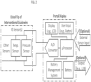
- the illustrated apparatus 100 includes a monitoring guidewire 102 and a portable display unit 104.
- the portable display unit 104 can be a handheld display unit, such that any and all aspects and embodiments described herein as being applicable to a portable display unit are also applicable to the disclosed handheld display unit.
- the handheld display unit can be equal to or less than 30cm x 30 cm x 30cm in size.
- the monitoring guidewire 102 is introduced into the vasculature of a patient with the assistance of conventional interventional equipment known to those skilled in the art, such as catheters.
- the portable display unit 104 can communicate with the monitoring guidewire 102 and can display information based on the communications received from the monitoring guidewire 102.
- the illustrated monitoring guidewire 102 can include several components, including a core wire 106 and one or more sensors 108 disposed in a distal region of the core wire 106.
- distal and proximal refer to physical directions within a blood vessel lumen. Specifically, in relation to the insertion point of a device into a patient, the term “distal” refers to the direction from the insertion point inwards into a blood vessel, and the term “proximal” refers to the direction from the inside of a blood vessel out towards the insertion point.
- proximal and distal can also refer to different ends of a device, with “proximal” being the end towards an insertion point into a blood vessel lumen and with “distal” being the end away from the insertion point.
- the one or more sensors 108 disposed in a distal region of the core wire 106 can include one or more hemodynamic pressure sensors and/or one or more temperature sensors.
- the pressure sensor(s) can be a piezo-resistive pressure sensor.
- the monitoring guidewire 102 can also include a protective structure 110 surrounding the sensor(s) 108, and can include a communication unit 112. The protective structure 110 of the monitoring guidewire 102 will be described in more detail later herein in connection with FIGS. 5-6 .
- the communication unit 112 can employ wireless communication technology such as bluetooth, WiFi (802.11), or any other wireless technology.
- the communication unit 112 can be a wireline communication unit that can include one or more wires for communicating electromagnetic signals and/or one or more optical fibers for communicating optical signals.
- the monitoring guidewire 102 can include other components that are not illustrated, such as a power source, A/D converters, application specific integrated circuits (ASIC), a processor, memory, timing circuitry, and/or other power, analog, or digital circuitry. Such components will be known to those skilled in the art.
- the portable display unit 104 can include a display screen 114, one or more batteries 116, memory and/or storage 118, a communication unit 120, power management unit 122, and a processor 124.
- the processor 124 can be a general purpose processor or can be an application specific integrated circuit.
- the display screen 114 can be a liquid crystal display, an organic light emitting diode display, or another type of display technology.
- the memory / storage 118 can include one or more of solid state memory / storage, magnetic disc storage, and/or any other type of memory / storage that will be known to those skilled in the art.
- the memory / storage 118 can include software instructions that are executed by the processor 124.
- the communication unit 120 can employ wireless communication technology such as bluetooth, WiFi (802.11), or any other wireless technology.
- the communication unit 120 can be a wireline communication unit that can include one or more wires for communicating electromagnetic signals and/or one or more optical fibers for communicating optical signals.
- the portable display unit 104 can include other components that are not illustrated, such as user interface, operating system software, display driver circuitry, A/D converters, application specific integrated circuits (ASIC), timing circuitry, and/or other power, analog, or digital circuitry. Such components will be known to those skilled in the art.
- the monitoring guidewire contains a pressure sensor and/or other sensors at the distal end.
- the electrical signals from the sensor(s) can be sent over a wire connection to the portable display unit.
- the portable display unit can include a communications port that receives external sensor input such as aortic output pressure (AO IN) from pressure transducers / hemodynamic systems (not shown).
- the portable display unit can also include an output communication port for outputting data to an external storage device, to another display, to a printer, and/or to a hemodynamic system (not shown).
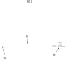
- the monitoring guidewire 302 can be approximately 180 centimeters in length. In other embodiments, the monitoring guidewire 302 can be another length.
- the monitoring guidewire 302 can have one or more sensors in the distal region 304 of the monitoring guidewire 302.
- the portable display unit 306 can have a small form factor such that it is a handheld display unit. In one embodiment, a handheld display unit can be equal to or less than 30cm x 30 cm x 30cm in size.
- FIG. 4 is a diagram of another exemplary embodiment of the disclosed intravascular diagnosis apparatus.
- the monitoring guidewire 402 can be attached and detached from a connector 406 of the portable display unit 400.
- the connector 406 can include a button (not shown) which opens an aperture in the connector 406.
- a user can press and hold the button of the connector 406 and insert the monitoring guidewire 402 into the aperture until the monitoring guidewire 402 is fully inserted into connector 406. Once inserted, the user can release the button, which will then secure the monitoring guidewire 402 in place and provide a connection between the monitoring guidewire 402 and connector 406.
- the connector 406 can engage the monitoring guidewire 402 by a screw engagement, a twist engagement, a snap engagement, or an interference fit.
- the described types of engagement are exemplary and do not limit the scope of the disclosed technology.
- Other types of ways for the connector 406 to engage the monitoring guidewire 402 are contemplated to be within the scope of the disclosed technology.
- the connector connection establishes a communicative connection between the monitoring guidewire 402 and the portable display unit 400.
- the monitoring guidewire 402 and the connector 406 can contain electrical wires that connect the monitoring guidewire 402 to the portable display unit 400 and convey signals from the monitoring guidewire sensor(s) to the portable display unit 400.
- the connector connection establishes a mechanical connection between the monitoring guidewire 402 and the connector 406 to control the guidewire 402 within a vasculature.
- the connector 406 is tethered to the main housing 410 of the portable display unit 400.
- the tether can be 6 inches to 12 inches long and can allow a user to manipulate the monitoring guidewire 402 freely without the portable display unit main housing 410 being an impediment.
- the tether can be another length.
- the connector can be a connection port integrated in the portable display unit main housing 410.
- the connector 406 establishes a communicative connection with the monitoring guidewire 402.
- a torquer (not shown) can be configured to engage the monitoring guidewire 402 to control the guidewire within a vasculature when the monitoring guidewire 402 is not mechanically and/or electrically connected to the connector 406.
- the torquer can be configured to engage the monitoring guidewire 402 to control the guidewire within a vasculature when the monitoring guidewire 402 is mechanically and/or electrically connected to the connector 406.
- the monitoring guidewire 402 does not need a torquer or the connector 406 for insertion into the vasculature of a patient and for navigation therein, and provides this capability by itself.
- the portable display unit 400 includes a display screen 404 that can display sensor measurements and/or computed information (e.g., fractional flow reserve ratio), in numerical format and/or in waveform format.
- the portable display unit 400 can include one or more buttons (not shown) or a touch screen to allow a user to provide input to the portable display unit 400.
- the screen 404 of the portable display unit can be folded in the main housing 410 before use to minimize the size of packaging when delivering the portal display unit 400.
- the user can pivot the screen 404 from the folded position to an open position (as illustrated), providing an appropriate viewing angle to the user for the diagnosis procedure.
- pivoting of the display screen 404 from the folded position to an open position acts as an ON switch that enables power to be delivered to the portable display unit.
- the portable display unit 400 also includes a communication port 408.
- the communication port 408 allows a user to connect the portable display unit 400 to an external system (not shown).
- the external system can communicate a sensor signal to the portable display unit 400 through the communication port 408.
- the sensor signal received at the communication port can be can be a pressure measurement and can be used in calculating fractional flow reserve.
- the monitoring guidewire 102 can include a protective structure 110 surrounding the sensor(s) 108.
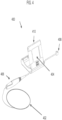
- a protective structure 502 surrounding the sensor(s) 510 at the distal region of the monitoring guidewire is shown.
- the protective structure 502 is a housing that has been laser etched with a particular pattern cut to provide flexibility and/or torque translation at the distal tip or portion of the monitoring guidewire where the sensor 510 resides.
- the sensor(s) 510 can be situated in the laser etched housing at a window 504 in the housing so as to allow blood to contact the sensor(s) 510 in order to take sensor measurements.
- the core wire 508 can be grinded to provide an appropriate profile for balancing flexibility and torque translation.
- the monitoring guidewire need not include a core wire 508. Rather, the protective structure 502 can extend along the entire monitoring guidewire or a substantial portion thereof, and can be laser etched along some or all portions to provide desired flexibility and/or torque translation.
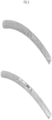
- FIG. 6 there is shown a diagram of two exemplary protective structures surrounding the sensor(s) at the distal region of a monitoring guidewire.
- One of the embodiments is a laser etched housing as described in connection with FIG. 5 .
- the other embodiment provides a coil over the sensor(s) as the protective structure. The coil is relaxed to create a window where the sensor(s) are located to allow blood to contact the sensor(s).
- the illustrated embodiments are exemplary and do not limit the scope of protective structures contemplated in the disclosed technology. Other protective structures are contemplated to be within the scope of the disclosed technology.
- the portable display unit 104 can be configured to operate for a predetermined duration or for a predetermined number of uses, and then be disposed.
- the battery 116 and/or power management unit 122 can implement these features so that the portable display unit 104 can be inoperable after being used for a particular duration or for a particular number of diagnosis procedures. Even so, the portable display unit 104 can be disposed while it is still operable, prior to it being inoperable.
- the predetermined duration can correspond to the approximate length of time of a single intravascular diagnosis procedure. In one embodiment, the predetermined duration can correspond to the approximate length of time of multiple diagnosis procedures, such as three procedures. In one embodiment, the predetermined duration can be twelve hours or twenty-four hours or several days.
- the portable display unit 104 can include one or more batteries 116 that are configured to power the portable display unit 104 for the desired duration, such that the batteries 116 are substantially depleted at the end of the desired duration. In one embodiment, the one or more batteries 116 are non-rechargeable, so that the portable display unit 104 is disposed after the batteries 116 are depleted.
- the power management unit 122 can control the operating time of the portable display unit 104 by preventing the portably display unit 104 from powering down after the display screen 114 is turned on. In such an embodiment, the portable display unit 104 will operate continuously until the batteries 116 are depleted or substantially depleted. The portable display unit 104 can be disposed prior to the batteries 116 being depleted, while the portable display unit 104 is still operable.
- the portable display unit 104 can track the number of diagnosis procedures performed and can be configured to be inoperable after a particular number of procedures has been performed. In one embodiment, the portable display unit 104 can track the number of diagnosis procedures performed by the number of times the portable display unit 114 has been turned on and/or off. In one embodiment, the portable display unit 104 can be configured to be inoperable after a single diagnosis procedure has been performed. In one aspect of the disclosed technology, the power management unit 122 can prevent the portable display unit 104 from being powered on after the particular number of procedures has been reached.
- the batteries 116 can be rechargeable and can be recharged by a power source of the portable display unit 104 and/or by a power source external to the portable display unit 104. Even when the batteries 116 are not yet depleted, the power management unit 122 can cause the portable display unit 104 to be inoperable by preventing the batteries 116 from powering the portable display unit 104.
- the intravascular diagnosis procedure will now be described with continuing reference to FIG. 1 and with reference to FIGS. 7-11 .
- Diagnosing the severity of one or more stenoses within the vasculature of a patient has been studied based on hemodynamic pressure measurements distal to a stenosis in comparison with aortic output pressure.
- the ratio of pressure distal to a stenosis to the aortic output pressure is known as "factional flow reserve", or FFR.
- the value of the FFR indicates the severity of the stenosis, and clinical data provides guidance on the type of surgical procedure that would be effective for particular FFR ranges.
- the disclosed technology includes multiple ways of computing FFR, including what will be referred to herein as “push-forward FFR”, “pull-back FFR”, and “simultaneous FFR”. Each of these can be implemented by software code or machine code stored in memory / storage 118 of the portable display unit 104 ( FIG. 1 ).
- the processor 124 can execute the software code to compute the FFR, and the resulting information can be displayed on the display screen 114.
- Each of the computation methods will now be described.
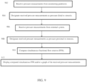
- Simultaneous FFR involves simultaneous pressure readings from two separate pressure sensors, and a computation of FFR in real-time as the pressure readings from the two separate pressure sensors are received.
- one pressure sensor is located in the monitoring guidewire 102, and is used to measure pressure distal to a stenosis in a patient.
- the pressure readings can be communicated by the communication unit 112 of the monitoring guidewire 102 to the communication unit 120 of the portable display unit 104
- This communication can be a wireless communication or can be a wireline communication through, for example, the connector illustrated in FIG. 3 .
- the other pressure sensor can measure aortic output pressure and is external to the apparatus 100 of FIG. 1 .
- the portable display unit 104 can designate the received pressure measurements as pressure distal to a stenosis (904).
- the external sensor readings can be communicated to the communication unit 120 of the portable display unit by, for example, the communication port illustrated in FIG. 3 (906).
- the portable display unit 104 can designate the received pressure measurements as pressure proximal to a stenosis (908).
- the moving means over time can compute the mean over a window of time that spans one heartbeat.
- the window of time can span less than one heartbeat or more than one heartbeat.
- the window can include newer measurements and remove older measurements to compute the moving means.
- the portable display unit 104 can receive pressure measurements and can compute the simultaneous FFR based on the received measurements.
- the portable display unit 104 can store the received pressure measurements and/or the computed simultaneous FFR in memory / storage 118, and can display the computed simultaneous FFR and/or a graph of the received pressure measurements on the display screen 114 (912).
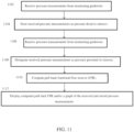
- push-forward FFR does not receive external pressure measurements.
- push-forward FFR is computed using pressure measurements from only the pressure sensor(s) 108 in the distal region of the monitoring guidewire 102.
- a stenosis can be located and, as shown in FIG. 8 , the monitoring guidewire can be inserted into a patient to a point proximal to the stenosis.
- Pressure can be measured at this position by the sensor(s) 108 and communicated by the communication unit 112 to the portable display unit 104 (1002).
- the portable display unit 104 can store the measurements in this position in the memory / storage 118 as pressure proximal to a stenosis (1004).
- the monitoring guidewire 102 can be pushed forward past the stenosis to a point distal to the stenosis, as illustrated in FIG. 7 .
- Pressure can be measured at this position by the sensor(s) 108 and communicated by the communication unit 112 to the portable display unit 104 (1006).
- the portal display unit 104 can designate the pressure measurements received at this position as pressure distal to the stenosis (1008).
- the portal display unit 104 can display the computed push-forward FFR and/or a graph of the received and stored pressure measurements (1012).
- Push-forward FFR can be computed in the case of one stenosis and can also be computed in the case of multiple stenosis.
- P saved are moving means over time of pressure measurements proximal to all of the stenosis.
- P saved are moving means over time computed based on recorded pressure measurements.
- P saved are moving means over time computed and recorded as pressure measurements are received, and the pressure measurements may or may not be recorded. For example, in the case of two stenoses, P saved are based on pressure measurements proximal to both the first and second stenosis.
- Push-forward FFR can be calculated in this position and displayed on the display screen 114.
- P sensor are based on real time pressure measurements distal to both of the two stenoses.
- Push-forward FFR can be calculated in this position and displayed on the display screen 114.
- push-forward FFR enables FFR to be computed and displayed as the monitoring guidewire 102 is pushed forward across one or more stenoses in a blood vessel lumen.
- the only measurements and/or moving means that need to be recorded for push-forward FFR computations are pressure measurements and/or moving means of pressure measurements proximal to all stenoses, and this is performed at the outset.
- pull-back FFR does not receive external pressure measurements. Rather, pull-back FFR is computed using pressure measurements from only the pressure sensor(s) 108 in the distal region of the monitoring guidewire 102.
- a stenosis can be located and, as shown in FIG. 7 , the monitoring guidewire can be inserted into a patient to a point distal to the stenosis. Pressure can be measured at this position by the sensor(s) 108 and communicated by the communication unit 112 to the portable display unit 104 (1102).
- the portable display unit 104 can store the measurements in this position in the memory / storage 118 as pressure distal to a stenosis (1104).
- the monitoring guidewire 102 can be pulled back through the stenosis to a point proximal to the stenosis, as illustrated in FIG. 8 .
- Pressure can be measured at this position by the sensor(s) 108 and communicated by the communication unit 112 to the portable display unit 104 (1106).
- the portable display unit 104 can designate the measurements received in this position as pressure proximal to a stenosis (1108).
- the portal display unit 104 can display the computed pull-back FFR and/or a graph of the received and stored pressure measurements (1112).
- Pull-back FFR can be computed in the case of one stenosis and can also be computed in the case of multiple stenosis.
- P sensor are based on real-time pressure measurements proximal to all of the stenosis, which are the final pressure measurements that are taken.
- the monitoring guidewire pressure sensor 108 is initially placed at a position distal to both the first and the second stenoses. Pressure can be measured at this position by the sensor(s) 108 and communicated by the communication unit 112 to the portable display unit 104.
- P saved_d1 are moving means over time computed later based on recorded pressure measurements.
- P saved_d1 are moving means over time computed and recorded while the pressure measurements are received in this position, and the pressure measurements may or may not be recorded.
- the memory / storage 118 can record the pressure measurements in this position and/or computed moving means over time based on such pressure measurements. Pull-back FFR cannot yet be calculated because there is no real-time measurement yet proximal to all of the stenoses.
- the monitoring guidewire 102 can be pulled back through the first stenosis to a point between the first and second stenosis. Pressure can be measured at this position by the sensor(s) 108 and communicated by the communication unit 112 to the portable display unit 104.
- P saved_d2 are moving means over time computed later based on recorded pressure measurements.
- P saved_d1 are moving means over time computed and recorded while the pressure measurements are received in this position, and the pressure measurements may or may not be recorded.
- the memory / storage 118 can record the pressure measurements in this position and/or computed moving means over time based on such pressure measurements.
- pull-back FFR cannot yet be calculated because there is no real-time measurement yet proximal to all of the stenoses.
- the monitoring guidewire 102 can be pulled back through the second stenosis to a point proximal to both the first and second stenosis. Real-time pressure can be measured at this position by the sensor(s) 108 and communicated by the communication unit 112 to the portable display unit 104.
- the portable display unit 104 is configured with capability to compute fractional flow reserve using any of the three ways.
- the portable display unit 104 can be configured to automatically use one of the three ways of computing fractional flow reserve.
- the portable display unit 104 can be configured to automatically select one of the three ways of computing fractional flow reserve when a condition is present and to automatically select another of the three ways of computing fractional flow reserve when other conditions are present.
- the portable display unit 104 can be configured to permit a user to manually select one of the three ways of computing fraction flow reserve.
- FFR fractional flow reserve
Landscapes
- Health & Medical Sciences (AREA)
- Life Sciences & Earth Sciences (AREA)
- Engineering & Computer Science (AREA)
- Medical Informatics (AREA)
- Physics & Mathematics (AREA)
- Veterinary Medicine (AREA)
- Biophysics (AREA)
- Pathology (AREA)
- Cardiology (AREA)
- Biomedical Technology (AREA)
- Heart & Thoracic Surgery (AREA)
- Public Health (AREA)
- Molecular Biology (AREA)
- Surgery (AREA)
- Animal Behavior & Ethology (AREA)
- General Health & Medical Sciences (AREA)
- Physiology (AREA)
- Vascular Medicine (AREA)
- Measuring Pulse, Heart Rate, Blood Pressure Or Blood Flow (AREA)
Claims (29)
- Appareil portable (100) destiné à un diagnostic intravasculaire, l'appareil portable comprenant :un fil-guide de surveillance (102) comprenant un fil central (106) et un capteur de pression (108) disposé dans une région distale du fil central ; etune unité d'affichage (104) configurée pour être inutilisable après un nombre prédéterminé d'utilisations ou après une durée prédéterminée d'utilisation, l'unité d'affichage (104) comprenant un processeur et un écran d'affichage (114), dans lequel l'unité d'affichage (104) est capable de recevoir une communication en provenance du fil-guide de surveillance (102), est configurée pour effectuer des calculs à l'aide du processeur sur la base de communications reçues en provenance du fil-guide de surveillance (102), et est configurée pour afficher des informations sur l'écran d'affichage (114) sur la base des calculs, dans lequel les calculs incluent le calcul de la réserve de débit fractionnaire.
- Appareil portable (100) selon la revendication 1, l'unité d'affichage (104) comprenant en outre une ou plusieurs batteries (116) configurées pour alimenter l'unité d'affichage pendant une durée prédéterminée d'utilisation, l'unité d'affichage étant configurée pour être inutilisable une fois que lesdites une ou plusieurs batteries (116) sont déchargées.
- Appareil portable (100) selon la revendication 2, dans lequel lesdites une ou plusieurs batteries (116) ne sont pas rechargeables.
- Appareil portable (100) selon la revendication 1, dans lequel l'unité d'affichage (104) est configurée pour être inutilisable après un nombre prédéterminé d'utilisations supérieur à un.
- Appareil portable (100) selon la revendication 4, dans lequel l'unit d'affichage (104) comprend en outre une ou plusieurs batteries (116) configurées pour alimenter l'unité d'affichage.
- Appareil portable (100) selon la revendication 5, dans lequel lesdites une ou plusieurs batteries (116) sont rechargeables par au moins l'une parmi : une source d'alimentation de l'unité d'affichage et une source d'alimentation externe à l'unité d'affichage.
- Appareil portable (100) selon la revendication 4, dans lequel le fil-guide de surveillance est à usage unique.
- Appareil portable (100) selon la revendication 1, dans lequel l'unité d'affichage est configurée pour être inutilisable après une seule utilisation.
- Appareil portable (100) selon la revendication 1, dans lequel l'unité d'affichage (104) et le fil-guide de surveillance (102) communiquent sans fil.
- Appareil portable (100) selon la revendication 1, dans lequel l'unité d'affichage (104) comprend en outre un connecteur configuré pour établir une connexion de communication avec le fil-guide de surveillance (102).
- Appareil portable (100) selon la revendication 10, dans lequel le connecteur est en outre configuré pour établir une connexion mécanique avec le fil-guide de surveillance (102) afin de commander le fil-guide à l'intérieur d'un système vasculaire.
- Appareil portable (100) selon la revendication 1, comprenant en outre un générateur de couple configuré pour être en prise avec le fil guide de surveillance (102) afin de commander le fil guide à l'intérieur d'un système vasculaire.
- Appareil portable (100) selon la revendication 1, dans lequel le fil-guide de surveillance (102) comprend en outre un boîtier entourant le capteur de pression (108), le boîtier étant gravé au laser pour conférer une flexibilité au boîtier.
- Appareil portable (100) selon la revendication 1, dans lequel le fil-guide de surveillance (102) comprend en outre une bobine flexible entourant le capteur de pression (108), la bobine ayant une portion détendue par-dessus le capteur.
- Appareil portable (100) selon la revendication 1, dans lequel la communication en provenance du fil-guide de surveillance (102) inclut des mesures en provenance du capteur de pression (108), et dans lequel les calculs à l'aide du processeur incluent le calcul de la réserve de débit fractionnaire sur la base de mesures de pression uniquement en provenance du capteur de pression (108) disposé dans la région distale du fil central.
- Appareil portable (100) selon la revendication 15, dans lequel la réserve de débit fractionnaire inclut une réserve de débit fractionnaire push-forward calculée comme suit :
 Psaved sont des moyens de déplacement dans le temps de mesures de pression enregistrées qui sont proximales par rapport à une première sténose,Psensor sont des moyens de déplacement dans le temps de mesures de pression en temps réel qui sont distales par rapport à la première sténose, etPra est une constante.
 - Appareil portable (100) selon la revendication 16, dans lequel Psensor sont des moyens de déplacement dans le temps de mesures de pression en temps réel qui sont distales par rapport à la première sténose et proximales par rapport à une deuxième sténose.
- Appareil portable (100) selon la revendication 16, dans lequel :Psaved sont des moyens de déplacement dans le temps de mesures de pression enregistrées qui sont proximales par rapport à la première sténose et proximales par rapport à une deuxième sténose, etPsensor sont des moyens de déplacement dans le temps de mesures de pression en temps réel qui sont distales par rapport à la première sténose et distales par rapport à la deuxième sténose.
- Appareil portable selon la revendication 15, dans lequel la réserve de débit fractionnaire inclut une réserve de débit fractionnaire pull-back calculée comme suit :
 Psaved sont des moyens de déplacement dans le temps de mesures de pression enregistrées qui sont distales par rapport à une première sténose,Psensor sont des moyens de déplacement dans le temps de mesures de pression en temps réel qui sont proximales par rapport à la première sténose, etPra est une constante.
 - Appareil portable (100) selon la revendication 19, dans lequel Psensor sont des moyens de déplacement dans le temps de mesures de pression en temps réel qui sont proximales par rapport à la première sténose et distales par rapport à une deuxième sténose.
- Appareil portable (100) selon la revendication 19, dans lequel :Psaved sont des moyens de déplacement dans le temps de mesures de pression enregistrées qui sont distales par rapport à la première sténose et distales par rapport à une deuxième sténose, etPsensor sont des moyens de déplacement dans le temps de mesures de pression en temps réel qui sont proximales par rapport à la première sténose et proximales par rapport à la deuxième sténose.
- Appareil portable (100) selon la revendication 15, dans lequel l'unité d'affichage (104) affiche sur l'écran d'affichage (114) la réserve de débit fractionnaire.
- Appareil portable (100) selon la revendication 15, dans lequel l'unité d'affichage (104) affiche un graphique des mesures de pression.
- Appareil portable (100) selon la revendication 1, dans lequel l'unité d'affichage (104) comprend en outre un port de communication configuré pour recevoir des communications qui incluent des mesures de pression.
- Appareil portable (100) selon la revendication 24, dans lequel les calculs à l'aide du processeur incluent le calcul d'une réserve de débit fractionnaire simultanée comme suit :
 Pport sont des moyens de déplacement dans le temps de mesures de pression en temps réel reçues au niveau du port de communication,Psensor sont des moyens de déplacement dans le temps de mesures de pression en temps réel en provenance du capteur de pression disposé dans la région distale du fil central, etPra est une constante.
 - Appareil portable (100) selon la revendication 24, dans lequel l'unité d'affichage est configurée avec la capacité de calculer la réserve de débit fractionnaire selon au moins deux de ces manières : en calculant la réserve de débit fractionnaire sur la base de mesures de pression uniquement en provenance du capteur de pression (108) disposé dans la région distale du fil central ; et en calculant la réserve de débit fractionnaire sur la base des mesures de pression en provenance du capteur de pression (108) et sur la base de mesures de pression reçues au niveau du port de communication.
- Appareil portable (100) selon la revendication 26, dans lequel l'unité d'affichage (104) est configurée pour utiliser automatiquement l'une desdites au moins deux manières de calculer la réserve de débit fractionnaire.
- Appareil portable (100) selon la revendication 26, dans lequel l'unité d'affichage est configurée pour sélectionner automatiquement l'une desdites au moins deux manières de calculer la réserve de débit fractionnaire lorsqu'une condition est présente, et pour sélectionner automatiquement une autre desdites au moins deux manières de calculer la réserve de débit fractionnaire lorsque la condition est absente.
- Appareil portable (100) selon la revendication 26, dans lequel l'unité d'affichage est configurée pour permettre à un utilisateur de sélectionner manuellement l'une desdites au moins deux manières de calculer la réserve de débit fractionnaire.
Applications Claiming Priority (3)
| Application Number | Priority Date | Filing Date | Title |
|---|---|---|---|
| US201361841517P | 2013-07-01 | 2013-07-01 | |
| US201461985858P | 2014-04-29 | 2014-04-29 | |
| PCT/US2014/045171 WO2015003024A2 (fr) | 2013-07-01 | 2014-07-01 | Appareil et procédé pour mesures intravasculaires |
Publications (4)
| Publication Number | Publication Date |
|---|---|
| EP2996552A2 EP2996552A2 (fr) | 2016-03-23 |
| EP2996552A4 EP2996552A4 (fr) | 2017-04-19 |
| EP2996552C0 EP2996552C0 (fr) | 2024-09-04 |
| EP2996552B1 true EP2996552B1 (fr) | 2024-09-04 |
Family
ID=52116272
Family Applications (1)
| Application Number | Title | Priority Date | Filing Date |
|---|---|---|---|
| EP14820180.9A Active EP2996552B1 (fr) | 2013-07-01 | 2014-07-01 | Appareil et procédé pour mesures intravasculaires |
Country Status (8)
| Country | Link |
|---|---|
| US (2) | US10702170B2 (fr) |
| EP (1) | EP2996552B1 (fr) |
| JP (1) | JP5976983B1 (fr) |
| KR (1) | KR101697908B1 (fr) |
| CN (1) | CN104902811B (fr) |
| AU (1) | AU2014284381B2 (fr) |
| CA (1) | CA2915252C (fr) |
| WO (1) | WO2015003024A2 (fr) |
Families Citing this family (9)
| Publication number | Priority date | Publication date | Assignee | Title |
|---|---|---|---|---|
| US10835183B2 (en) | 2013-07-01 | 2020-11-17 | Zurich Medical Corporation | Apparatus and method for intravascular measurements |
| KR102568758B1 (ko) * | 2015-06-23 | 2023-08-18 | 쥬어리크 메디컬 코퍼레이션 | 혈관 내 측정을 위한 장치 및 방법 |
| WO2017079111A1 (fr) * | 2015-11-02 | 2017-05-11 | Heartware, Inc. | Procédés et systèmes de prédiction d'événement néfaste à l'aide de données de fonctionnement de pompe |
| IL254009A0 (en) * | 2016-08-18 | 2017-09-28 | Nutriseal Lp | A system and method for directing the location of a device inserted into the body |
| CN106264514B (zh) * | 2016-09-27 | 2023-05-05 | 上海爱声生物医疗科技有限公司 | 一种无线血流储备分数测量系统 |
| US10548815B2 (en) * | 2018-04-30 | 2020-02-04 | Envizion Medical Ltd. | Insertion device positioning guidance system and method |
| EP3692893A1 (fr) * | 2019-02-05 | 2020-08-12 | Koninklijke Philips N.V. | Capteur doté d'un boîtier adapté |
| CN114376546B (zh) * | 2020-12-28 | 2024-03-12 | 深圳北芯生命科技股份有限公司 | 一种支持双诊断模式的系统 |
| CN117617927B (zh) * | 2024-01-25 | 2024-06-18 | 浙江巴泰医疗科技有限公司 | 压力导丝及其制造方法 |
Citations (3)
| Publication number | Priority date | Publication date | Assignee | Title |
|---|---|---|---|---|
| US6651669B1 (en) * | 1999-09-07 | 2003-11-25 | Scimed Life Systems, Inc. | Systems and methods to identify and disable re-used single use devices based on cataloging catheter usage |
| WO2007062315A2 (fr) * | 2005-11-21 | 2007-05-31 | Acist Medical Systems, Inc. | Systeme d'injection de fluides medicaux |
| US20110270179A1 (en) * | 2010-04-28 | 2011-11-03 | Ouyang Xiaolong | Single use medical devices |
Family Cites Families (209)
| Publication number | Priority date | Publication date | Assignee | Title |
|---|---|---|---|---|
| US5178153A (en) | 1984-03-08 | 1993-01-12 | Einzig Robert E | Fluid flow sensing apparatus for in vivo and industrial applications employing novel differential optical fiber pressure sensors |
| US4867173A (en) | 1986-06-30 | 1989-09-19 | Meadox Surgimed A/S | Steerable guidewire |
| US4691709A (en) | 1986-07-01 | 1987-09-08 | Cordis Corporation | Apparatus for measuring velocity of blood flow in a blood vessel |
| SE454045B (sv) | 1986-08-04 | 1988-03-28 | Radisensor Ab | Ledare for mekanisk styrning av en kateter vid hjert- och kerlundersokningar |
| US4777951A (en) | 1986-09-19 | 1988-10-18 | Mansfield Scientific, Inc. | Procedure and catheter instrument for treating patients for aortic stenosis |
| US5163445A (en) | 1987-04-10 | 1992-11-17 | Cardiometrics, Inc. | Apparatus, system and method for measuring spatial average velocity and/or volumetric flow of blood in a vessel and screw joint for use therewith |
| US5113868A (en) | 1987-06-01 | 1992-05-19 | The Regents Of The University Of Michigan | Ultraminiature pressure sensor with addressable read-out circuit |
| US4953553A (en) | 1989-05-11 | 1990-09-04 | Advanced Cardiovascular Systems, Inc. | Pressure monitoring guidewire with a flexible distal portion |
| US4884579A (en) | 1988-04-18 | 1989-12-05 | Target Therapeutics | Catheter guide wire |
| SE8801517L (sv) | 1988-04-22 | 1989-10-23 | Radisensor Ab | Kateter foer intravaskulaer tryckmaetning |
| US4901731A (en) | 1988-04-27 | 1990-02-20 | Millar Instruments, Inc. | Single sensor pressure differential device |
| US5873821A (en) * | 1992-05-18 | 1999-02-23 | Non-Invasive Technology, Inc. | Lateralization spectrophotometer |
| US5065769A (en) | 1988-11-23 | 1991-11-19 | Boston Scientific Corporation | Small diameter guidewires of multi-filar, cross-wound coils |
| US4928693A (en) | 1989-03-13 | 1990-05-29 | Schneider (Usa), Inc. | Pressure monitor catheter |
| US5063935A (en) | 1989-04-27 | 1991-11-12 | C. R. Bard, Inc. | Catheter guidewire with varying radiopacity |
| US5313957A (en) * | 1990-01-05 | 1994-05-24 | Medamicus, Inc. | Guide wire mounted pressure transducer |
| SE506135C2 (sv) | 1990-07-11 | 1997-11-17 | Radi Medical Systems | Sensor- och ledarkonstruktion |
| US5040543A (en) | 1990-07-25 | 1991-08-20 | C. R. Bard, Inc. | Movable core guidewire |
| US5699796A (en) | 1993-01-29 | 1997-12-23 | Cardima, Inc. | High resolution intravascular signal detection |
| US5226421A (en) | 1992-03-06 | 1993-07-13 | Cardiometrics, Inc. | Doppler elongate flexible member having an inflatable balloon mounted thereon |
| US5706809A (en) | 1993-01-29 | 1998-01-13 | Cardima, Inc. | Method and system for using multiple intravascular sensing devices to detect electrical activity |
| US5645082A (en) | 1993-01-29 | 1997-07-08 | Cardima, Inc. | Intravascular method and system for treating arrhythmia |
| US5873835A (en) | 1993-04-29 | 1999-02-23 | Scimed Life Systems, Inc. | Intravascular pressure and flow sensor |
| US5358409A (en) | 1993-08-31 | 1994-10-25 | Cardiometrics, Inc. | Rotary connector for flexible elongate member having electrical properties |
| ATE255361T1 (de) | 1993-10-01 | 2003-12-15 | Target Therapeutics Inc | Mehrpoliger katheter und mehrpoliger führungsdraht zur messung der elektrischen herzaktivität |
| US5517989A (en) | 1994-04-01 | 1996-05-21 | Cardiometrics, Inc. | Guidewire assembly |
| US5412994A (en) | 1994-06-14 | 1995-05-09 | Cook; James D. | Offset pressure sensor |
| WO1996007351A1 (fr) | 1994-09-02 | 1996-03-14 | Cardiometrics, Inc. | Capteur de pression ultra-miniaturise et fil de guidage equipe de ce dernier et procede associe |
| US5797856A (en) | 1995-01-05 | 1998-08-25 | Cardiometrics, Inc. | Intravascular guide wire and method |
| EP0738495B1 (fr) | 1995-04-18 | 2002-06-26 | Schneider (Europe) GmbH | Fil de guidage pour la mesure de pression |
| US5668320A (en) | 1995-06-19 | 1997-09-16 | Cardiometrics, Inc. | Piezoresistive pressure transducer circuitry accommodating transducer variability |
| SE9600333D0 (sv) | 1995-06-22 | 1996-01-30 | Radi Medical Systems | Sensor arrangement |
| US20030069522A1 (en) | 1995-12-07 | 2003-04-10 | Jacobsen Stephen J. | Slotted medical device |
| JP3737554B2 (ja) | 1996-01-09 | 2006-01-18 | 株式会社東海理化電機製作所 | センサ機能を備えたカテーテル |
| US6004279A (en) | 1996-01-16 | 1999-12-21 | Boston Scientific Corporation | Medical guidewire |
| SE9600334D0 (sv) | 1996-01-30 | 1996-01-30 | Radi Medical Systems | Combined flow, pressure and temperature sensor |
| US6440088B1 (en) | 1996-05-24 | 2002-08-27 | Precision Vascular Systems, Inc. | Hybrid catheter guide wire apparatus and method |
| US5690120A (en) | 1996-05-24 | 1997-11-25 | Sarcos, Inc. | Hybrid catheter guide wire apparatus |
| US6017319A (en) | 1996-05-24 | 2000-01-25 | Precision Vascular Systems, Inc. | Hybrid tubular guide wire for catheters |
| US6248083B1 (en) | 1997-03-25 | 2001-06-19 | Radi Medical Systems Ab | Device for pressure measurements |
| ES2246530T3 (es) | 1997-03-25 | 2006-02-16 | Radi Medical Systems Ab | Conector hembra. |
| JP3679419B2 (ja) | 1997-03-25 | 2005-08-03 | ラディ・メディカル・システムズ・アクチェボラーグ | ガイド・ワイヤ組み立て体及びそれを使用したシステム |
| EP0879615A1 (fr) | 1997-05-21 | 1998-11-25 | Schneider (Europe) GmbH | Fil de guidage avec détection de pression |
| US5938624A (en) | 1997-09-10 | 1999-08-17 | Radi Medical Systems Ab | Male connector with a continous surface for a guide wire and method therefor |
| US6033366A (en) | 1997-10-14 | 2000-03-07 | Data Sciences International, Inc. | Pressure measurement device |
| US9254143B2 (en) | 1998-02-25 | 2016-02-09 | Revascular Therapeutics, Inc. | Guidewire for crossing occlusions or stenoses having a shapeable distal end |
| US6824550B1 (en) | 2000-04-06 | 2004-11-30 | Norbon Medical, Inc. | Guidewire for crossing occlusions or stenosis |
| US20060074442A1 (en) | 2000-04-06 | 2006-04-06 | Revascular Therapeutics, Inc. | Guidewire for crossing occlusions or stenoses |
| US20080140101A1 (en) | 2006-12-07 | 2008-06-12 | Revascular Therapeutic, Inc. | Apparatus for crossing occlusions or stenoses |
| US6089103A (en) | 1998-05-06 | 2000-07-18 | Radi Medical Systems Ab | Method of flow measurements |
| US6162182A (en) | 1998-08-26 | 2000-12-19 | Becton, Dickinson And Company | Pressure tip cannula |
| US6193669B1 (en) | 1998-12-11 | 2001-02-27 | Florence Medical Ltd. | System and method for detecting, localizing, and characterizing occlusions, stent positioning, dissections and aneurysms in a vessel |
| US6312380B1 (en) | 1998-12-23 | 2001-11-06 | Radi Medical Systems Ab | Method and sensor for wireless measurement of physiological variables |
| US6142958A (en) | 1998-12-23 | 2000-11-07 | Radi Medical Systems Ab | Sensor and guide wire assembly |
| GB2345543A (en) | 1999-01-06 | 2000-07-12 | Intravascular Res Ltd | Ultrasonic visualisation system with remote components |
| US6210339B1 (en) | 1999-03-03 | 2001-04-03 | Endosonics Corporation | Flexible elongate member having one or more electrical contacts |
| US6471656B1 (en) * | 1999-06-25 | 2002-10-29 | Florence Medical Ltd | Method and system for pressure based measurements of CFR and additional clinical hemodynamic parameters |
| US20030032886A1 (en) | 1999-03-09 | 2003-02-13 | Elhanan Dgany | System for determining coronary flow reserve (CFR) value for a stenosed blood vessel, CFR processor therefor, and method therefor |
| US6409677B1 (en) | 1999-05-27 | 2002-06-25 | Radi Medical Systems Ab | Method for temperature compensation in a combined pressure and temperature sensor |
| EP1055392B1 (fr) | 1999-05-27 | 2008-03-19 | Radi Medical Systems Ab | Procédé de compensation de température dans un capteur combinant pression et température |
| US6265792B1 (en) | 1999-09-08 | 2001-07-24 | Endosonics Corporation | Medical device having precision interconnect |
| WO2001021057A2 (fr) | 1999-09-22 | 2001-03-29 | Florence Medical Ltd. | Procede et systeme pour determiner la reserve de debit fractionnaire (ffr) sur la base du mesurage de debit |
| US6579246B2 (en) | 1999-12-22 | 2003-06-17 | Sarcos, Lc | Coronary guidewire system |
| US6672172B2 (en) | 2000-01-31 | 2004-01-06 | Radi Medical Systems Ab | Triggered flow measurement |
| DE60001445T2 (de) | 2000-03-21 | 2003-10-23 | Radi Medical Systems Ab, Uppsala | Auf Resonanz basierendes Druckwandlersystem |
| US6615067B2 (en) | 2000-03-21 | 2003-09-02 | Radi Medical Systems Ab | Method and device for measuring physical characteristics in a body |
| US6565514B2 (en) * | 2000-08-25 | 2003-05-20 | Radi Medical Systems Ab | Method and system for determining physiological variables |
| WO2002085442A1 (fr) | 2001-04-19 | 2002-10-31 | Radi Medical Systems Ab | Systeme combine de detecteur pression-volume et de fil-guide combines |
| WO2002101347A1 (fr) | 2001-06-08 | 2002-12-19 | Radi Medical Systems Ab | Capteur de pression miniaturise |
| CA2449433A1 (fr) * | 2001-06-20 | 2003-01-03 | Microvention, Inc. | Dispositifs medicaux a gainages polymeres integraux ou partiels et procedes de fabrication |
| AU2002326135A1 (en) | 2001-09-10 | 2003-03-24 | Florence Medical Ltd. | Individual ffr determination for lesions of a multi-lesioned blood vessel |
| ES2319186T3 (es) | 2001-11-07 | 2009-05-05 | Radi Medical Systems Ab | Conector macho resistente a la flexion para un cable de guia. |
| US6908442B2 (en) | 2001-11-07 | 2005-06-21 | Radi Medical Systems Ab | Bending resistant male connector for a guide wire |
| SE523337C2 (sv) | 2001-11-07 | 2004-04-13 | Radi Medical Systems | Böjbeständig hankontakt till en styrtråd |
| US7018346B2 (en) | 2001-12-18 | 2006-03-28 | Scimed Life Systems, Inc. | Guide wire with adjustable flexibility |
| US7134994B2 (en) * | 2002-05-20 | 2006-11-14 | Volcano Corporation | Multipurpose host system for invasive cardiovascular diagnostic measurement acquisition and display |
| US7878984B2 (en) | 2002-07-25 | 2011-02-01 | Boston Scientific Scimed, Inc. | Medical device for navigation through anatomy and method of making same |
| US8162856B2 (en) | 2002-09-23 | 2012-04-24 | Volcano Corporation | Sensor catheter having reduced cross-talk wiring arrangements |
| ATE435670T1 (de) | 2003-03-31 | 2009-07-15 | Radi Medical Systems | Medizinisches gerät mit druckmessung in einem ventrikel zur steuerung eines herzschrittmachers. |
| JP2006524553A (ja) | 2003-04-28 | 2006-11-02 | ボード オブ リージェンツ, ザ ユニバーシティ オブ テキサス システム | カテーテル画像化プローブ及び方法 |
| US20040225232A1 (en) | 2003-05-09 | 2004-11-11 | Radi Medical Systems Ab | Sensor guide wire |
| US7144378B2 (en) * | 2003-10-31 | 2006-12-05 | Arnott Richard J | Quick-release torquer apparatus for delivering and maintaining a medical guideware |
| US7931603B2 (en) | 2003-11-21 | 2011-04-26 | Radi Medical Systems Ab | Sensor and guide wire assembly |
| US7326204B2 (en) | 2004-01-16 | 2008-02-05 | St. Jude Medical, Atrial Fibrillation Division, Inc. | Brush electrode and method for ablation |
| US8012145B2 (en) | 2004-04-30 | 2011-09-06 | Volcano Corporation | Medical hub having transparent observation section |
| EP1758501A1 (fr) | 2004-05-26 | 2007-03-07 | Martil Instruments B.V. | Catheter et dispositif de gestion de donnees portatif |
| US10258285B2 (en) | 2004-05-28 | 2019-04-16 | St. Jude Medical, Atrial Fibrillation Division, Inc. | Robotic surgical system and method for automated creation of ablation lesions |
| US7645233B2 (en) * | 2004-06-07 | 2010-01-12 | Radi Medical Systems Ab | Powering a guide wire mounted sensor for intra-vascular measurements of physiological variables by means of inductive coupling |
| US7263894B2 (en) | 2004-06-07 | 2007-09-04 | Radi Medical Systems Ab | Sensor and guide wire assembly |
| US20060052700A1 (en) | 2004-09-08 | 2006-03-09 | Radi Medical Systems Ab | Pressure measurement system |
| US9326756B2 (en) | 2006-05-17 | 2016-05-03 | St. Jude Medical, Atrial Fibrillation Division, Inc. | Transseptal catheterization assembly and methods |
| US8277386B2 (en) | 2004-09-27 | 2012-10-02 | Volcano Corporation | Combination sensor guidewire and methods of use |
| US20060135864A1 (en) * | 2004-11-24 | 2006-06-22 | Westerlund L E | Peri-orbital trauma monitor and ocular pressure / peri-orbital edema monitor for non-ophthalmic surgery |
| JP5328159B2 (ja) * | 2005-03-01 | 2013-10-30 | セルカコア・ラボラトリーズ・インコーポレーテッド | 多波長センサ発光体 |
| US7878981B2 (en) * | 2005-03-01 | 2011-02-01 | Checkpoint Surgical, Llc | Systems and methods for intra-operative stimulation |
| WO2006116719A2 (fr) | 2005-04-28 | 2006-11-02 | St. Jude Medical, Atrial Fibrillation Division, Inc. | Pointe atraumatique pelable, et corps pour catheter ou gaine |
| US20080091193A1 (en) | 2005-05-16 | 2008-04-17 | James Kauphusman | Irrigated ablation catheter having magnetic tip for magnetic field control and guidance |
| US7857810B2 (en) | 2006-05-16 | 2010-12-28 | St. Jude Medical, Atrial Fibrillation Division, Inc. | Ablation electrode assembly and methods for improved control of temperature and minimization of coagulation and tissue damage |
| US8777929B2 (en) | 2005-06-28 | 2014-07-15 | St. Jude Medical, Atrial Fibrillation Division, Inc. | Auto lock for catheter handle |
| US8267872B2 (en) | 2005-07-07 | 2012-09-18 | St. Jude Medical, Cardiology Division, Inc. | Steerable guide wire with torsionally stable tip |
| SE0501889L (sv) | 2005-08-25 | 2007-02-26 | Millicore Ab | Kärlresistansmätare |
| US8229545B2 (en) | 2005-09-15 | 2012-07-24 | St. Jude Medical, Atrial Fibrillation Division, Inc. | System and method for mapping complex fractionated electrogram information |
| US7775988B2 (en) | 2005-09-30 | 2010-08-17 | Radi Medical Systems Ab | Method for determining the blood flow in a coronary artery |
| US7988633B2 (en) | 2005-10-12 | 2011-08-02 | Volcano Corporation | Apparatus and method for use of RFID catheter intelligence |
| WO2007047974A2 (fr) | 2005-10-20 | 2007-04-26 | Board Of Regents, The University Of Texas System | Pointe de catheter optique rotative destinee a une tomographie par coherence optique |
| US8369922B2 (en) | 2005-12-06 | 2013-02-05 | St. Jude Medical Atrial Fibrillation Division, Inc. | Method for displaying catheter electrode-tissue contact in electro-anatomic mapping and navigation system |
| US8597183B2 (en) | 2005-12-09 | 2013-12-03 | Pneumoflex Systems, Llc | Involuntary contraction induced pressure as a medical diagnostic tool using involuntary reflex cough test |
| ATE539336T1 (de) | 2006-03-21 | 2012-01-15 | Radi Medical Systems | Drucksensor |
| WO2007115314A2 (fr) | 2006-04-04 | 2007-10-11 | The Spectranetics Corporation | Fil de guidage assisté par laser PRESENTant un axe à rigidité variable |
| US20070255145A1 (en) | 2006-04-28 | 2007-11-01 | Radi Medical Systems Ab | Sensor and guide wire assembly |
| DE602007006859D1 (de) | 2006-04-28 | 2010-07-15 | Radi Medical Systems | Sensor und Führungsdrahtanordnung |
| US20080091169A1 (en) | 2006-05-16 | 2008-04-17 | Wayne Heideman | Steerable catheter using flat pull wires and having torque transfer layer made of braided flat wires |
| US20080234660A2 (en) | 2006-05-16 | 2008-09-25 | Sarah Cumming | Steerable Catheter Using Flat Pull Wires and Method of Making Same |
| US7988639B2 (en) | 2006-05-17 | 2011-08-02 | St. Jude Medical, Atrial Fibrillation Division, Inc. | System and method for complex geometry modeling of anatomy using multiple surface models |
| US20070270741A1 (en) | 2006-05-17 | 2007-11-22 | Hassett James A | Transseptal needle assembly and methods |
| US8480636B2 (en) | 2006-05-17 | 2013-07-09 | St. Jude Medical, Atrial Fibrillation Division, Inc. | Catheter with aspiration passageway |
| US7774051B2 (en) | 2006-05-17 | 2010-08-10 | St. Jude Medical, Atrial Fibrillation Division, Inc. | System and method for mapping electrophysiology information onto complex geometry |
| US20070299403A1 (en) | 2006-06-23 | 2007-12-27 | Crowe John E | Directional introducer |
| US20070299438A1 (en) | 2006-06-23 | 2007-12-27 | Holzbaur Michael C | Torque transfer agent for introducer and method |
| US7678109B2 (en) | 2006-06-23 | 2010-03-16 | St. Jude Medical, Atrial Fibrillation Division, Inc. | Ablation device and method comprising movable ablation elements |
| US8052683B2 (en) | 2006-06-23 | 2011-11-08 | St. Jude Medical, Atrial Fibrillation Division, Inc. | Device for ablation and visualization |
| US8551020B2 (en) | 2006-09-13 | 2013-10-08 | Boston Scientific Scimed, Inc. | Crossing guidewire |
| US8174395B2 (en) | 2006-11-20 | 2012-05-08 | St. Jude Medical Systems Ab | Transceiver unit in a measurement system |
| EP1922988B1 (fr) | 2006-11-20 | 2015-04-08 | St. Jude Medical Systems AB | Unité émetteur-récepteur dans un système de mesure de la pression sanguine |
| US7967761B2 (en) | 2006-12-01 | 2011-06-28 | Radi Medical Systems Ab | Sensor and guide wire assembly |
| US8556914B2 (en) | 2006-12-15 | 2013-10-15 | Boston Scientific Scimed, Inc. | Medical device including structure for crossing an occlusion in a vessel |
| US8382689B2 (en) | 2007-02-08 | 2013-02-26 | St. Jude Medical, Atrial Fibrillation Division, Inc. | Device and method for high intensity focused ultrasound ablation with acoustic lens |
| US8265745B2 (en) | 2006-12-29 | 2012-09-11 | St. Jude Medical, Atrial Fibillation Division, Inc. | Contact sensor and sheath exit sensor |
| US8182466B2 (en) | 2006-12-29 | 2012-05-22 | St. Jude Medical, Atrial Fibrillation Division, Inc. | Dual braided catheter shaft |
| US9549689B2 (en) | 2007-03-09 | 2017-01-24 | St. Jude Medical, Atrial Fibrillation Division, Inc. | System and method for correction of inhomogeneous fields |
| US7706891B2 (en) | 2007-03-21 | 2010-04-27 | St. Jude Medical, Atrial Fibrillation Division, Inc. | Catheter employing shape memory alloy shaping wire or pull wire and method of its manufacture |
| US8979837B2 (en) | 2007-04-04 | 2015-03-17 | St. Jude Medical, Atrial Fibrillation Division, Inc. | Flexible tip catheter with extended fluid lumen |
| US20080262474A1 (en) | 2007-04-20 | 2008-10-23 | Boston Scientific Scimed, Inc. | Medical device |
| US8734440B2 (en) | 2007-07-03 | 2014-05-27 | St. Jude Medical, Atrial Fibrillation Division, Inc. | Magnetically guided catheter |
| US20090036832A1 (en) | 2007-08-03 | 2009-02-05 | Boston Scientific Scimed, Inc. | Guidewires and methods for manufacturing guidewires |
| US8105246B2 (en) | 2007-08-03 | 2012-01-31 | Boston Scientific Scimed, Inc. | Elongate medical device having enhanced torque and methods thereof |
| EP2042091B1 (fr) | 2007-09-25 | 2014-05-14 | Radi Medical Systems Ab | Fil de guidage à détection de pression |
| US8216151B2 (en) | 2007-09-25 | 2012-07-10 | Radi Medical Systems Ab | Pressure wire assembly |
| DE102007048880B4 (de) | 2007-10-11 | 2009-07-30 | Up Management Gmbh | Blutdruckmessvorrichtung und Verfahren zum Betreiben einer Blutdruckmessvorrichtung |
| US9566418B2 (en) | 2007-10-26 | 2017-02-14 | St. Jude Medical Coordination Center Bvba | Sensor guide wire with micro-cable winding |
| WO2009054800A1 (fr) | 2007-10-26 | 2009-04-30 | Radi Medical Systems Ab | Fil guide de détection |
| US8858591B2 (en) | 2007-10-31 | 2014-10-14 | Radi Medical Systems Ab | Method and device for sealing a puncture hole in a bodily organ |
| US8974398B2 (en) * | 2007-11-08 | 2015-03-10 | St. Jude Medical Coordination Center Bvba | Removable energy source for sensor guidewire |
| US7998089B2 (en) | 2007-11-08 | 2011-08-16 | Radi Medical Systems Ab | Method of making a guide wire based assembly and reusing an energy source |
| US8162934B2 (en) | 2007-12-21 | 2012-04-24 | St. Jude Medical, Atrial Fibrillation Division, Inc. | Medical catheter assembly with deflection pull ring and distal tip interlock |
| US10660690B2 (en) | 2007-12-28 | 2020-05-26 | St. Jude Medical, Atrial Fibrillation Division, Inc. | System and method for measurement of an impedance using a catheter such as an ablation catheter |
| US8684999B2 (en) | 2007-12-31 | 2014-04-01 | St. Jude Medical, Atrial Fibrillation Division, Inc. | Catheter shaft and method of manufacture |
| US20090177119A1 (en) | 2008-01-03 | 2009-07-09 | Boston Scientific Scimed, Inc. | Articulating intracorporeal medical device |
| US9095685B2 (en) | 2008-01-23 | 2015-08-04 | Mediguide Ltd. | Sensor mounted flexible guidewire |
| IL196660A (en) | 2008-01-23 | 2014-09-30 | Mediguide Ltd | Flexible conductive catheter with sensor |
| CA2716657A1 (fr) | 2008-03-05 | 2009-09-11 | Robert Hoch | Catheter capteur de pression |
| US8684962B2 (en) | 2008-03-27 | 2014-04-01 | St. Jude Medical, Atrial Fibrillation Division, Inc. | Robotic catheter device cartridge |
| US8343096B2 (en) | 2008-03-27 | 2013-01-01 | St. Jude Medical, Atrial Fibrillation Division, Inc. | Robotic catheter system |
| US8437832B2 (en) | 2008-06-06 | 2013-05-07 | Biosense Webster, Inc. | Catheter with bendable tip |
| RU2478338C2 (ru) * | 2008-09-11 | 2013-04-10 | Эсист Медикал Системз, Инк. | Устройство и способ доставки физиологического датчика |
| AU2009292925A1 (en) | 2008-09-22 | 2010-03-25 | Dtherapeutics, Llc | Devices, systems, and methods for determining fractional flow reserve |
| US20110009694A1 (en) * | 2009-07-10 | 2011-01-13 | Schultz Eric E | Hand-held minimally dimensioned diagnostic device having integrated distal end visualization |
| US20100125197A1 (en) | 2008-11-18 | 2010-05-20 | Fishel Robert S | Method and apparatus for addressing vascular stenotic lesions |
| CN102639303B (zh) | 2008-12-08 | 2015-09-30 | 血管科学有限公司 | 用于在产品中形成切口的微切割机 |
| US8795254B2 (en) | 2008-12-10 | 2014-08-05 | Boston Scientific Scimed, Inc. | Medical devices with a slotted tubular member having improved stress distribution |
| US20110066047A1 (en) | 2009-03-17 | 2011-03-17 | Claude Belleville | Eccentric pressure catheter with guidewire compatibility |
| US20110054487A1 (en) | 2009-09-02 | 2011-03-03 | Circulite, Inc. | Coaxial transseptal guide-wire and needle assembly |
| SE534637C2 (sv) | 2009-09-15 | 2011-11-01 | St Jude Medical Systems Ab | Snabbväxlingsguideenhet med trycksensor |
| US8376991B2 (en) | 2009-11-09 | 2013-02-19 | St. Jude Medical, Atrial Fibrillation Division, Inc. | Device for reducing axial shortening of catheter or sheath due to repeated deflection |
| US20110160680A1 (en) | 2009-12-29 | 2011-06-30 | Cook Incorporated | Wire guide with cannula |
| US20110160832A1 (en) | 2009-12-30 | 2011-06-30 | Amit Cohen | Electrical Metering of Active Fixation Lead Extension |
| US8478384B2 (en) * | 2010-01-19 | 2013-07-02 | Lightlab Imaging, Inc. | Intravascular optical coherence tomography system with pressure monitoring interface and accessories |
| SE534291C2 (sv) * | 2010-01-27 | 2011-06-28 | St Jude Medical Systems Ab | Sensorstyrtrådsanordning och system för intravaskulära mätningar av en fysiologisk variabel |
| GB2479340A (en) | 2010-03-10 | 2011-10-12 | Imp Innovations Ltd | Method and apparatus for the measurement of a fluid flow restriction in a vessel |
| US8551021B2 (en) | 2010-03-31 | 2013-10-08 | Boston Scientific Scimed, Inc. | Guidewire with an improved flexural rigidity profile |
| WO2012173697A1 (fr) | 2011-06-13 | 2012-12-20 | Angiometrix Corporation | Ensembles fils-guides multifontionnels et système pour analyser des paramètres anatomiques et fonctionnels |
| SE535022C2 (sv) | 2010-06-30 | 2012-03-20 | St Jude Medical Systems Ab | Sensorguidewire innefattande en sensorkapsel med multipla hål |
| ES2556781T3 (es) | 2010-09-29 | 2016-01-20 | St. Jude Medical Coordination Center Bvba | Alambre de guía de sensor |
| US8340766B2 (en) | 2010-10-07 | 2012-12-25 | St. Jude Medical, Atrial Fibrillation Division, Inc. | Method and system for identifying cardiac arrhythmia driver sites |
| CA2808202C (fr) | 2010-11-09 | 2013-11-05 | Opsens Inc. | Fil-guide avec capteur de pression interne |
| US8391956B2 (en) * | 2010-11-18 | 2013-03-05 | Robert D. Zellers | Medical device location systems, devices and methods |
| US8764683B2 (en) | 2010-12-29 | 2014-07-01 | Mediguide Ltd. | Medical device guidewire with a position sensor |
| GB201100137D0 (en) | 2011-01-06 | 2011-02-23 | Davies Helen C S | Apparatus and method of assessing a narrowing in a fluid tube |
| EP2667770A4 (fr) | 2011-01-30 | 2016-06-22 | Guided Interventions Inc | Système de détection de pression sanguine à l'aide d'un fil-guide de détection de pression |
| CN103796578B (zh) | 2011-05-11 | 2016-08-24 | 阿西斯特医疗系统有限公司 | 血管内感测方法和系统 |
| JP2013039305A (ja) | 2011-08-19 | 2013-02-28 | Asahi Intecc Co Ltd | ガイドワイヤ |
| US9339348B2 (en) | 2011-08-20 | 2016-05-17 | Imperial Colege of Science, Technology and Medicine | Devices, systems, and methods for assessing a vessel |
| EP2747634A4 (fr) | 2011-08-22 | 2015-05-06 | Lake Region Mfg Inc D B A Lake Region Medical | Fil-guide multiconducteur, de faible profil |
| US8911448B2 (en) * | 2011-09-23 | 2014-12-16 | Orthosensor, Inc | Device and method for enabling an orthopedic tool for parameter measurement |
| EP2757947B1 (fr) | 2011-09-23 | 2019-04-10 | Orthosensor | Dispositif de mesure de charge et d'emplacement de vertèbres |
| US8696584B2 (en) | 2011-10-05 | 2014-04-15 | 3Dt Holdings, Llc | Devices, systems and methods for determining fractional flow reserve in the presence of a catheter |
| US20130116579A1 (en) | 2011-10-28 | 2013-05-09 | St. Jude Medical Systems Ab | Medical system, and a method in relation to the medical system |
| WO2013082032A1 (fr) | 2011-11-28 | 2013-06-06 | Mazar Scott T | Fil-guide orientable à capteur de pression |
| FR2984720B1 (fr) | 2011-12-22 | 2014-03-07 | Univ Grenoble 1 | Procede et dispositif de surveillance de la mesure de la pression arterielle par catheterisme arteriel d'un patient |
| US10736519B2 (en) | 2012-01-19 | 2020-08-11 | Philips Image Guided Therapy Corporation | Interface devices, systems, and methods for use with intravascular pressure monitoring devices |
| US10373700B2 (en) | 2012-03-13 | 2019-08-06 | Siemens Healthcare Gmbh | Non-invasive functional assessment of coronary artery stenosis including simulation of hyperemia by changing resting microvascular resistance |
| US20130338538A1 (en) | 2012-04-16 | 2013-12-19 | Agency For Science, Technology And Research | Guide wire arrangement |
| US20130274618A1 (en) | 2012-04-17 | 2013-10-17 | Boston Scientific Scimed, Inc. | Guidewire system for use in transcatheter aortic valve implantation procedures |
| US10226185B2 (en) | 2012-05-03 | 2019-03-12 | St. Jude Medical Coordination Center Bvba | Tube and sensor guide wire comprising tube |
| US9364640B2 (en) | 2012-05-07 | 2016-06-14 | St. Jude Medical Atrial Fibrillation Division, Inc. | Medical device guidewire with helical cutout and coating |
| EP2856098B1 (fr) | 2012-05-25 | 2019-10-16 | Vascular Imaging Corporation | Capteur de pression à fibre optique |
| US20130324842A1 (en) | 2012-05-29 | 2013-12-05 | The Johns Hopkins University | Method for Estimating Pressure Gradients and Fractional Flow Reserve from Computed Tomography Angiography: Transluminal Attenuation Flow Encoding |
| US20140005558A1 (en) | 2012-06-29 | 2014-01-02 | Boston Scientific Scimed, Inc. | Pressure sensing guidewire |
| WO2014025255A1 (fr) | 2012-08-06 | 2014-02-13 | Wellinq Medical B.V. | Cathéter à capteur de pression et procédé associé |
| WO2014035995A1 (fr) | 2012-08-27 | 2014-03-06 | Boston Scientific Scimed, Inc. | Dispositifs médicaux de détection de pression et systèmes de dispositifs médicaux |
| US9974446B2 (en) | 2012-08-31 | 2018-05-22 | Volcano Corporation | Mounting structures for components of intravascular devices |
| WO2014036477A1 (fr) | 2012-08-31 | 2014-03-06 | Volcano Corporation | Dispositifs intravasculaires de détection de pression à dérive réduite, et systèmes et procédés associés |
| CA2882944A1 (fr) | 2012-09-17 | 2014-03-20 | Boston Scientific Scimed, Inc. | Fil-guide detectant la pression |
| US20140180028A1 (en) | 2012-12-21 | 2014-06-26 | Volcano Corporation | Guidewire with adjustable tip |
| US9924903B2 (en) | 2012-12-27 | 2018-03-27 | Volcano Corporation | Pressure-sensing guide wire with sliding pressure sensor |
| WO2014105578A1 (fr) | 2012-12-27 | 2014-07-03 | Volcano Corporation | Fil-guide intravasculaire avec partie d'extrémité distale hyperflexible |
| WO2014140883A1 (fr) | 2013-03-15 | 2014-09-18 | St. Jude Medical Systems Ab | Dispositif de fil de guidage de capteur et système comprenant un dispositif de fil de guidage de capteur |
| US20140276117A1 (en) | 2013-03-15 | 2014-09-18 | Volcano Corporation | Intravascular Devices, Systems, and Methods |
| EP2968854B1 (fr) | 2013-03-15 | 2019-04-24 | Boston Scientific Scimed, Inc. | Fil-guide à détection de pression |
-
2014
- 2014-07-01 AU AU2014284381A patent/AU2014284381B2/en active Active
- 2014-07-01 US US14/321,776 patent/US10702170B2/en active Active
- 2014-07-01 WO PCT/US2014/045171 patent/WO2015003024A2/fr not_active Ceased
- 2014-07-01 EP EP14820180.9A patent/EP2996552B1/fr active Active
- 2014-07-01 CN CN201480002922.4A patent/CN104902811B/zh active Active
- 2014-07-01 JP JP2016524335A patent/JP5976983B1/ja active Active
- 2014-07-01 CA CA2915252A patent/CA2915252C/fr active Active
- 2014-07-01 KR KR1020167001577A patent/KR101697908B1/ko active Active
-
2020
- 2020-06-15 US US16/946,290 patent/US11471061B2/en active Active
Patent Citations (3)
| Publication number | Priority date | Publication date | Assignee | Title |
|---|---|---|---|---|
| US6651669B1 (en) * | 1999-09-07 | 2003-11-25 | Scimed Life Systems, Inc. | Systems and methods to identify and disable re-used single use devices based on cataloging catheter usage |
| WO2007062315A2 (fr) * | 2005-11-21 | 2007-05-31 | Acist Medical Systems, Inc. | Systeme d'injection de fluides medicaux |
| US20110270179A1 (en) * | 2010-04-28 | 2011-11-03 | Ouyang Xiaolong | Single use medical devices |
Also Published As
| Publication number | Publication date |
|---|---|
| AU2014284381B2 (en) | 2019-04-18 |
| JP2016529957A (ja) | 2016-09-29 |
| KR20160025564A (ko) | 2016-03-08 |
| WO2015003024A3 (fr) | 2015-04-09 |
| US20150005648A1 (en) | 2015-01-01 |
| EP2996552C0 (fr) | 2024-09-04 |
| US10702170B2 (en) | 2020-07-07 |
| JP5976983B1 (ja) | 2016-08-24 |
| CA2915252C (fr) | 2023-03-21 |
| EP2996552A2 (fr) | 2016-03-23 |
| US11471061B2 (en) | 2022-10-18 |
| CN104902811A (zh) | 2015-09-09 |
| WO2015003024A2 (fr) | 2015-01-08 |
| EP2996552A4 (fr) | 2017-04-19 |
| KR101697908B1 (ko) | 2017-01-18 |
| AU2014284381A1 (en) | 2016-01-07 |
| CA2915252A1 (fr) | 2015-01-08 |
| CN104902811B (zh) | 2019-08-16 |
| US20200305728A1 (en) | 2020-10-01 |
Similar Documents
| Publication | Publication Date | Title |
|---|---|---|
| US11471061B2 (en) | Apparatus and method for intravascular measurements | |
| EP3313496B1 (fr) | Appareil pour mesures intravasculaires | |
| US20210068755A1 (en) | Apparatus and method for intravascular measurements | |
| US9084539B2 (en) | Wireless pressure wire system with integrated power | |
| JP2016533785A (ja) | 血管内デバイス、システム、及び方法 | |
| US20210204818A1 (en) | Diagnostic Systems and Methods Including Temperature-Sensing Vascular Devices | |
| US8372021B2 (en) | Measuring and testing device for retractable medical devices |
Legal Events
| Date | Code | Title | Description |
|---|---|---|---|
| PUAI | Public reference made under article 153(3) epc to a published international application that has entered the european phase |
Free format text: ORIGINAL CODE: 0009012 |
|
| 17P | Request for examination filed |
Effective date: 20151216 |
|
| AK | Designated contracting states |
Kind code of ref document: A2 Designated state(s): AL AT BE BG CH CY CZ DE DK EE ES FI FR GB GR HR HU IE IS IT LI LT LU LV MC MK MT NL NO PL PT RO RS SE SI SK SM TR |
|
| AX | Request for extension of the european patent |
Extension state: BA ME |
|
| DAX | Request for extension of the european patent (deleted) | ||
| RIC1 | Information provided on ipc code assigned before grant |
Ipc: A61B 5/00 20060101AFI20170103BHEP Ipc: A61B 5/02 20060101ALI20170103BHEP Ipc: A61B 5/026 20060101ALI20170103BHEP |
|
| A4 | Supplementary search report drawn up and despatched |
Effective date: 20170320 |
|
| RIC1 | Information provided on ipc code assigned before grant |
Ipc: A61B 5/0215 20060101ALI20170314BHEP Ipc: A61B 5/00 20060101AFI20170314BHEP Ipc: A61B 5/026 20060101ALI20170314BHEP Ipc: A61B 5/02 20060101ALI20170314BHEP |
|
| STAA | Information on the status of an ep patent application or granted ep patent |
Free format text: STATUS: EXAMINATION IS IN PROGRESS |
|
| 17Q | First examination report despatched |
Effective date: 20200520 |
|
| GRAP | Despatch of communication of intention to grant a patent |
Free format text: ORIGINAL CODE: EPIDOSNIGR1 |
|
| STAA | Information on the status of an ep patent application or granted ep patent |
Free format text: STATUS: GRANT OF PATENT IS INTENDED |
|
| INTG | Intention to grant announced |
Effective date: 20240307 |
|
| GRAS | Grant fee paid |
Free format text: ORIGINAL CODE: EPIDOSNIGR3 |
|
| GRAA | (expected) grant |
Free format text: ORIGINAL CODE: 0009210 |
|
| STAA | Information on the status of an ep patent application or granted ep patent |
Free format text: STATUS: THE PATENT HAS BEEN GRANTED |
|
| AK | Designated contracting states |
Kind code of ref document: B1 Designated state(s): AL AT BE BG CH CY CZ DE DK EE ES FI FR GB GR HR HU IE IS IT LI LT LU LV MC MK MT NL NO PL PT RO RS SE SI SK SM TR |
|
| REG | Reference to a national code |
Ref country code: GB Ref legal event code: FG4D |
|
| REG | Reference to a national code |
Ref country code: CH Ref legal event code: EP |
|
| REG | Reference to a national code |
Ref country code: IE Ref legal event code: FG4D |
|
| REG | Reference to a national code |
Ref country code: DE Ref legal event code: R096 Ref document number: 602014090821 Country of ref document: DE |
|
| U01 | Request for unitary effect filed |
Effective date: 20240927 |
|
| U07 | Unitary effect registered |
Designated state(s): AT BE BG DE DK EE FI FR IT LT LU LV MT NL PT RO SE SI Effective date: 20241024 |
|
| PG25 | Lapsed in a contracting state [announced via postgrant information from national office to epo] |
Ref country code: NO Free format text: LAPSE BECAUSE OF FAILURE TO SUBMIT A TRANSLATION OF THE DESCRIPTION OR TO PAY THE FEE WITHIN THE PRESCRIBED TIME-LIMIT Effective date: 20241204 |
|
| PG25 | Lapsed in a contracting state [announced via postgrant information from national office to epo] |
Ref country code: GR Free format text: LAPSE BECAUSE OF FAILURE TO SUBMIT A TRANSLATION OF THE DESCRIPTION OR TO PAY THE FEE WITHIN THE PRESCRIBED TIME-LIMIT Effective date: 20241205 Ref country code: PL Free format text: LAPSE BECAUSE OF FAILURE TO SUBMIT A TRANSLATION OF THE DESCRIPTION OR TO PAY THE FEE WITHIN THE PRESCRIBED TIME-LIMIT Effective date: 20240904 |
|
| PG25 | Lapsed in a contracting state [announced via postgrant information from national office to epo] |
Ref country code: HR Free format text: LAPSE BECAUSE OF FAILURE TO SUBMIT A TRANSLATION OF THE DESCRIPTION OR TO PAY THE FEE WITHIN THE PRESCRIBED TIME-LIMIT Effective date: 20240904 |
|
| PG25 | Lapsed in a contracting state [announced via postgrant information from national office to epo] |
Ref country code: ES Free format text: LAPSE BECAUSE OF FAILURE TO SUBMIT A TRANSLATION OF THE DESCRIPTION OR TO PAY THE FEE WITHIN THE PRESCRIBED TIME-LIMIT Effective date: 20240904 Ref country code: RS Free format text: LAPSE BECAUSE OF FAILURE TO SUBMIT A TRANSLATION OF THE DESCRIPTION OR TO PAY THE FEE WITHIN THE PRESCRIBED TIME-LIMIT Effective date: 20241204 |
|
| PG25 | Lapsed in a contracting state [announced via postgrant information from national office to epo] |
Ref country code: RS Free format text: LAPSE BECAUSE OF FAILURE TO SUBMIT A TRANSLATION OF THE DESCRIPTION OR TO PAY THE FEE WITHIN THE PRESCRIBED TIME-LIMIT Effective date: 20241204 Ref country code: PL Free format text: LAPSE BECAUSE OF FAILURE TO SUBMIT A TRANSLATION OF THE DESCRIPTION OR TO PAY THE FEE WITHIN THE PRESCRIBED TIME-LIMIT Effective date: 20240904 Ref country code: NO Free format text: LAPSE BECAUSE OF FAILURE TO SUBMIT A TRANSLATION OF THE DESCRIPTION OR TO PAY THE FEE WITHIN THE PRESCRIBED TIME-LIMIT Effective date: 20241204 Ref country code: HR Free format text: LAPSE BECAUSE OF FAILURE TO SUBMIT A TRANSLATION OF THE DESCRIPTION OR TO PAY THE FEE WITHIN THE PRESCRIBED TIME-LIMIT Effective date: 20240904 Ref country code: GR Free format text: LAPSE BECAUSE OF FAILURE TO SUBMIT A TRANSLATION OF THE DESCRIPTION OR TO PAY THE FEE WITHIN THE PRESCRIBED TIME-LIMIT Effective date: 20241205 Ref country code: ES Free format text: LAPSE BECAUSE OF FAILURE TO SUBMIT A TRANSLATION OF THE DESCRIPTION OR TO PAY THE FEE WITHIN THE PRESCRIBED TIME-LIMIT Effective date: 20240904 |
|
| PG25 | Lapsed in a contracting state [announced via postgrant information from national office to epo] |
Ref country code: IS Free format text: LAPSE BECAUSE OF FAILURE TO SUBMIT A TRANSLATION OF THE DESCRIPTION OR TO PAY THE FEE WITHIN THE PRESCRIBED TIME-LIMIT Effective date: 20250104 |
|
| PG25 | Lapsed in a contracting state [announced via postgrant information from national office to epo] |
Ref country code: SM Free format text: LAPSE BECAUSE OF FAILURE TO SUBMIT A TRANSLATION OF THE DESCRIPTION OR TO PAY THE FEE WITHIN THE PRESCRIBED TIME-LIMIT Effective date: 20240904 |
|
| PG25 | Lapsed in a contracting state [announced via postgrant information from national office to epo] |
Ref country code: CZ Free format text: LAPSE BECAUSE OF FAILURE TO SUBMIT A TRANSLATION OF THE DESCRIPTION OR TO PAY THE FEE WITHIN THE PRESCRIBED TIME-LIMIT Effective date: 20240904 |
|
| PG25 | Lapsed in a contracting state [announced via postgrant information from national office to epo] |
Ref country code: SK Free format text: LAPSE BECAUSE OF FAILURE TO SUBMIT A TRANSLATION OF THE DESCRIPTION OR TO PAY THE FEE WITHIN THE PRESCRIBED TIME-LIMIT Effective date: 20240904 |
|
| PLBE | No opposition filed within time limit |
Free format text: ORIGINAL CODE: 0009261 |
|
| STAA | Information on the status of an ep patent application or granted ep patent |
Free format text: STATUS: NO OPPOSITION FILED WITHIN TIME LIMIT |
|
| 26N | No opposition filed |
Effective date: 20250605 |
|
| U20 | Renewal fee for the european patent with unitary effect paid |
Year of fee payment: 12 Effective date: 20250728 |
|
| PGFP | Annual fee paid to national office [announced via postgrant information from national office to epo] |
Ref country code: IE Payment date: 20250728 Year of fee payment: 12 |
|
| REG | Reference to a national code |
Ref country code: CH Ref legal event code: H13 Free format text: ST27 STATUS EVENT CODE: U-0-0-H10-H13 (AS PROVIDED BY THE NATIONAL OFFICE) Effective date: 20260224 |
|
| GBPC | Gb: european patent ceased through non-payment of renewal fee |
Effective date: 20250701 |
|
| PG25 | Lapsed in a contracting state [announced via postgrant information from national office to epo] |
Ref country code: GB Free format text: LAPSE BECAUSE OF NON-PAYMENT OF DUE FEES Effective date: 20250701 |
|
| PG25 | Lapsed in a contracting state [announced via postgrant information from national office to epo] |
Ref country code: CH Free format text: LAPSE BECAUSE OF NON-PAYMENT OF DUE FEES Effective date: 20250731 |