EP2995251B1 - Dispositif de mesure d'humidité intrabuccale - Google Patents
Dispositif de mesure d'humidité intrabuccale Download PDFInfo
- Publication number
- EP2995251B1 EP2995251B1 EP14882866.8A EP14882866A EP2995251B1 EP 2995251 B1 EP2995251 B1 EP 2995251B1 EP 14882866 A EP14882866 A EP 14882866A EP 2995251 B1 EP2995251 B1 EP 2995251B1
- Authority
- EP
- European Patent Office
- Prior art keywords
- detection unit
- pressing force
- moisture amount
- measuring device
- moisture
- Prior art date
- Legal status (The legal status is an assumption and is not a legal conclusion. Google has not performed a legal analysis and makes no representation as to the accuracy of the status listed.)
- Active
Links
- 238000001514 detection method Methods 0.000 claims description 116
- 238000003825 pressing Methods 0.000 claims description 113
- 238000005259 measurement Methods 0.000 claims description 97
- 239000010409 thin film Substances 0.000 claims description 13
- 238000000034 method Methods 0.000 description 18
- 239000000463 material Substances 0.000 description 10
- 206010013781 dry mouth Diseases 0.000 description 8
- 239000011347 resin Substances 0.000 description 8
- 229920005989 resin Polymers 0.000 description 8
- 208000005946 Xerostomia Diseases 0.000 description 7
- 230000000694 effects Effects 0.000 description 7
- 210000004877 mucosa Anatomy 0.000 description 6
- 230000005489 elastic deformation Effects 0.000 description 5
- 239000000758 substrate Substances 0.000 description 5
- 210000003813 thumb Anatomy 0.000 description 4
- RYGMFSIKBFXOCR-UHFFFAOYSA-N Copper Chemical compound [Cu] RYGMFSIKBFXOCR-UHFFFAOYSA-N 0.000 description 3
- 229910052782 aluminium Inorganic materials 0.000 description 3
- XAGFODPZIPBFFR-UHFFFAOYSA-N aluminium Chemical compound [Al] XAGFODPZIPBFFR-UHFFFAOYSA-N 0.000 description 3
- 238000001574 biopsy Methods 0.000 description 3
- 238000007796 conventional method Methods 0.000 description 3
- 229910052802 copper Inorganic materials 0.000 description 3
- 239000010949 copper Substances 0.000 description 3
- 239000010408 film Substances 0.000 description 3
- 210000003811 finger Anatomy 0.000 description 3
- 229910052751 metal Inorganic materials 0.000 description 3
- 239000002184 metal Substances 0.000 description 3
- 210000000258 minor salivary gland Anatomy 0.000 description 3
- 238000011160 research Methods 0.000 description 3
- 230000001954 sterilising effect Effects 0.000 description 3
- 238000004659 sterilization and disinfection Methods 0.000 description 3
- 238000005406 washing Methods 0.000 description 3
- 208000021386 Sjogren Syndrome Diseases 0.000 description 2
- 238000005452 bending Methods 0.000 description 2
- 201000011510 cancer Diseases 0.000 description 2
- 239000000919 ceramic Substances 0.000 description 2
- 230000008859 change Effects 0.000 description 2
- 239000011248 coating agent Substances 0.000 description 2
- 238000000576 coating method Methods 0.000 description 2
- 230000007246 mechanism Effects 0.000 description 2
- 230000010355 oscillation Effects 0.000 description 2
- 238000005728 strengthening Methods 0.000 description 2
- 238000011282 treatment Methods 0.000 description 2
- 208000032484 Accidental exposure to product Diseases 0.000 description 1
- 208000001705 Mouth breathing Diseases 0.000 description 1
- 206010028980 Neoplasm Diseases 0.000 description 1
- 206010035669 Pneumonia aspiration Diseases 0.000 description 1
- 208000026375 Salivary gland disease Diseases 0.000 description 1
- 239000000853 adhesive Substances 0.000 description 1
- 230000001070 adhesive effect Effects 0.000 description 1
- 230000003321 amplification Effects 0.000 description 1
- 201000009408 aspiration pneumonitis Diseases 0.000 description 1
- 210000005178 buccal mucosa Anatomy 0.000 description 1
- 238000004891 communication Methods 0.000 description 1
- 239000004020 conductor Substances 0.000 description 1
- 238000005260 corrosion Methods 0.000 description 1
- 230000007797 corrosion Effects 0.000 description 1
- 230000002542 deteriorative effect Effects 0.000 description 1
- 206010012601 diabetes mellitus Diseases 0.000 description 1
- 238000003745 diagnosis Methods 0.000 description 1
- 208000037265 diseases, disorders, signs and symptoms Diseases 0.000 description 1
- 208000035475 disorder Diseases 0.000 description 1
- 239000003814 drug Substances 0.000 description 1
- PCHJSUWPFVWCPO-UHFFFAOYSA-N gold Chemical compound [Au] PCHJSUWPFVWCPO-UHFFFAOYSA-N 0.000 description 1
- 239000010931 gold Substances 0.000 description 1
- 229910052737 gold Inorganic materials 0.000 description 1
- 230000036541 health Effects 0.000 description 1
- 208000015181 infectious disease Diseases 0.000 description 1
- 238000003780 insertion Methods 0.000 description 1
- 230000037431 insertion Effects 0.000 description 1
- 239000012212 insulator Substances 0.000 description 1
- 208000017169 kidney disease Diseases 0.000 description 1
- 239000004973 liquid crystal related substance Substances 0.000 description 1
- 238000012986 modification Methods 0.000 description 1
- 230000004048 modification Effects 0.000 description 1
- 238000003199 nucleic acid amplification method Methods 0.000 description 1
- 238000011275 oncology therapy Methods 0.000 description 1
- 238000005457 optimization Methods 0.000 description 1
- 238000002638 palliative care Methods 0.000 description 1
- 230000002093 peripheral effect Effects 0.000 description 1
- 230000000704 physical effect Effects 0.000 description 1
- 238000007747 plating Methods 0.000 description 1
- 230000002265 prevention Effects 0.000 description 1
- 238000012545 processing Methods 0.000 description 1
- 210000003296 saliva Anatomy 0.000 description 1
- 230000035945 sensitivity Effects 0.000 description 1
- 230000000391 smoking effect Effects 0.000 description 1
- 208000024891 symptom Diseases 0.000 description 1
- 230000009897 systematic effect Effects 0.000 description 1
Images


Classifications
-
- A—HUMAN NECESSITIES
- A61—MEDICAL OR VETERINARY SCIENCE; HYGIENE
- A61B—DIAGNOSIS; SURGERY; IDENTIFICATION
- A61B5/00—Measuring for diagnostic purposes; Identification of persons
- A61B5/42—Detecting, measuring or recording for evaluating the gastrointestinal, the endocrine or the exocrine systems
- A61B5/4261—Evaluating exocrine secretion production
- A61B5/4277—Evaluating exocrine secretion production saliva secretion
-
- A—HUMAN NECESSITIES
- A61—MEDICAL OR VETERINARY SCIENCE; HYGIENE
- A61B—DIAGNOSIS; SURGERY; IDENTIFICATION
- A61B5/00—Measuring for diagnostic purposes; Identification of persons
- A61B5/05—Detecting, measuring or recording for diagnosis by means of electric currents or magnetic fields; Measuring using microwaves or radio waves
- A61B5/053—Measuring electrical impedance or conductance of a portion of the body
- A61B5/0537—Measuring body composition by impedance, e.g. tissue hydration or fat content
-
- A—HUMAN NECESSITIES
- A61—MEDICAL OR VETERINARY SCIENCE; HYGIENE
- A61B—DIAGNOSIS; SURGERY; IDENTIFICATION
- A61B5/00—Measuring for diagnostic purposes; Identification of persons
- A61B5/45—For evaluating or diagnosing the musculoskeletal system or teeth
- A61B5/4538—Evaluating a particular part of the muscoloskeletal system or a particular medical condition
- A61B5/4542—Evaluating the mouth, e.g. the jaw
- A61B5/4552—Evaluating soft tissue within the mouth, e.g. gums or tongue
-
- A—HUMAN NECESSITIES
- A61—MEDICAL OR VETERINARY SCIENCE; HYGIENE
- A61B—DIAGNOSIS; SURGERY; IDENTIFICATION
- A61B5/00—Measuring for diagnostic purposes; Identification of persons
- A61B5/68—Arrangements of detecting, measuring or recording means, e.g. sensors, in relation to patient
- A61B5/6801—Arrangements of detecting, measuring or recording means, e.g. sensors, in relation to patient specially adapted to be attached to or worn on the body surface
- A61B5/6843—Monitoring or controlling sensor contact pressure
-
- A—HUMAN NECESSITIES
- A61—MEDICAL OR VETERINARY SCIENCE; HYGIENE
- A61B—DIAGNOSIS; SURGERY; IDENTIFICATION
- A61B5/00—Measuring for diagnostic purposes; Identification of persons
- A61B5/74—Details of notification to user or communication with user or patient ; user input means
- A61B5/7405—Details of notification to user or communication with user or patient ; user input means using sound
-
- A—HUMAN NECESSITIES
- A61—MEDICAL OR VETERINARY SCIENCE; HYGIENE
- A61B—DIAGNOSIS; SURGERY; IDENTIFICATION
- A61B2560/00—Constructional details of operational features of apparatus; Accessories for medical measuring apparatus
- A61B2560/02—Operational features
- A61B2560/0266—Operational features for monitoring or limiting apparatus function
-
- A—HUMAN NECESSITIES
- A61—MEDICAL OR VETERINARY SCIENCE; HYGIENE
- A61B—DIAGNOSIS; SURGERY; IDENTIFICATION
- A61B2560/00—Constructional details of operational features of apparatus; Accessories for medical measuring apparatus
- A61B2560/02—Operational features
- A61B2560/029—Operational features adapted for auto-initiation
-
- A—HUMAN NECESSITIES
- A61—MEDICAL OR VETERINARY SCIENCE; HYGIENE
- A61B—DIAGNOSIS; SURGERY; IDENTIFICATION
- A61B2560/00—Constructional details of operational features of apparatus; Accessories for medical measuring apparatus
- A61B2560/04—Constructional details of apparatus
- A61B2560/0406—Constructional details of apparatus specially shaped apparatus housings
- A61B2560/0425—Ergonomically shaped housings
-
- A—HUMAN NECESSITIES
- A61—MEDICAL OR VETERINARY SCIENCE; HYGIENE
- A61B—DIAGNOSIS; SURGERY; IDENTIFICATION
- A61B2560/00—Constructional details of operational features of apparatus; Accessories for medical measuring apparatus
- A61B2560/04—Constructional details of apparatus
- A61B2560/0443—Modular apparatus
-
- A—HUMAN NECESSITIES
- A61—MEDICAL OR VETERINARY SCIENCE; HYGIENE
- A61B—DIAGNOSIS; SURGERY; IDENTIFICATION
- A61B2560/00—Constructional details of operational features of apparatus; Accessories for medical measuring apparatus
- A61B2560/04—Constructional details of apparatus
- A61B2560/0462—Apparatus with built-in sensors
- A61B2560/0468—Built-in electrodes
-
- A—HUMAN NECESSITIES
- A61—MEDICAL OR VETERINARY SCIENCE; HYGIENE
- A61B—DIAGNOSIS; SURGERY; IDENTIFICATION
- A61B2562/00—Details of sensors; Constructional details of sensor housings or probes; Accessories for sensors
- A61B2562/02—Details of sensors specially adapted for in-vivo measurements
- A61B2562/0209—Special features of electrodes classified in A61B5/24, A61B5/25, A61B5/283, A61B5/291, A61B5/296, A61B5/053
- A61B2562/0214—Capacitive electrodes
-
- A—HUMAN NECESSITIES
- A61—MEDICAL OR VETERINARY SCIENCE; HYGIENE
- A61B—DIAGNOSIS; SURGERY; IDENTIFICATION
- A61B2562/00—Details of sensors; Constructional details of sensor housings or probes; Accessories for sensors
- A61B2562/02—Details of sensors specially adapted for in-vivo measurements
- A61B2562/0247—Pressure sensors
-
- A—HUMAN NECESSITIES
- A61—MEDICAL OR VETERINARY SCIENCE; HYGIENE
- A61B—DIAGNOSIS; SURGERY; IDENTIFICATION
- A61B2562/00—Details of sensors; Constructional details of sensor housings or probes; Accessories for sensors
- A61B2562/02—Details of sensors specially adapted for in-vivo measurements
- A61B2562/0261—Strain gauges
-
- A—HUMAN NECESSITIES
- A61—MEDICAL OR VETERINARY SCIENCE; HYGIENE
- A61B—DIAGNOSIS; SURGERY; IDENTIFICATION
- A61B2562/00—Details of sensors; Constructional details of sensor housings or probes; Accessories for sensors
- A61B2562/02—Details of sensors specially adapted for in-vivo measurements
- A61B2562/029—Humidity sensors
Definitions
- the present invention relates to an intraoral moisture measuring device for measuring intraoral moisture.
- xerostomia called dry mouth
- xerostomia is generally considered to be developed, for example, by systematic illness such as diabetes or renal disease, mouth breathing or smoking, side effects of medicine or treatment, salivary gland disease, central or peripheral nervous disorder, or psychological stress.
- Xerostomia is often found especially in the elderly. It has been reported that approximately 40% of the elderly suffer from xerostomia.
- an intraoral moisture measuring device including a capacitance type sensor is increasingly used (see Patent Literature 1, for example).
- a capacitance type intraoral moisture measuring device a moisture amount in mucosa is measured on the basis of a change in capacitance between two electrodes. Therefore, the sensor unit needs to be abutted against a measurement site with a suitable pressing force (load).
- a suitable pressing force load
- a technique has been proposed in which a sensor is disposed in a slider, which is biased in a pressing direction by a spring, in a skin moisture measuring device, for example, and the magnitude of a pressing force is determined on the basis of a travel distance of the slider (see Patent Literature 2).
- a sensor holding structure capable of easily deforming, is disposed on the rear side of a sensor in an intraoral moisture measuring device, so that the direction of the sensor can be freely changed when being pressed (see Patent Literature 3).
- Patent Literature 3 The subject-matter of the preamble of claim 1 is known from Patent Literature 3 and Patent Literature 4.
- Patent Literature 2 With the technique described in Patent Literature 2, however, the structure in the vicinity of the sensor becomes complicated, and it is therefore difficult to apply such a technique to an intraoral moisture measuring device which requires the sensor to be inserted into a narrow space in a mouth. Furthermore, since too much cost is needed for replacement, it is difficult to make the sensor and its adjacent parts disposable (expendable). With the technique described in Patent Literature 3, the direction of the sensor is freely changed by the sensor holding structure. Thus, a pressure sensor needs to be disposed on the rear side of the sensor in order to measure a pressing force. This leads to a complicated and high-cost structure in the vicinity of the sensor. Again, it is difficult to make such a structure disposable.
- the new diagnostic criteria for the Sjogren syndrome which produces xerostomia as its prominent symptom, includes labial minor salivary gland biopsy.
- rejection against biopsy is often seen in medical practice, and therefore the emergence of an intraoral moisture measuring device capable of measuring even the state of a labial minor salivary gland, which is present at a relatively deep position under the labial mucosa, with high accuracy has been desired as a replacement for the biopsy.
- an object of the present invention to provide an intraoral moisture measuring device capable of measuring intraoral moisture in a simple and highly-accurate manner.
- the present invention is an intraoral moisture measuring device including: a swing member that swings with respect to a main body about a predetermined swing center; a moisture amount detection unit provided at a tip of the swing member, for detecting a moisture amount by being directly or indirectly abutted against a measurement site in a mouth; and a biasing member for biasing the swing member in one of swing directions.
- the present invention is characterized in that the swing center is disposed in the main body in the intraoral moisture measuring device with the above-mentioned means.
- the present invention is characterized in that the intraoral moisture measuring device with the above-mentioned means includes a pressing force detection unit for detecting a pressing force to the measurement site by the moisture amount detection unit.
- the present invention is characterized in that the pressing force detection unit is disposed inside the main body in the intraoral moisture measuring device with the above-mentioned means.
- the intraoral moisture measuring device with the above-mentioned means includes a control unit for controlling the moisture amount detection unit and the pressing force detection unit, and the control unit includes pressing force determination means for determining if the pressing force detected by the pressing force detection unit falls within an appropriate range.
- control unit includes measurement starting means that starts moisture amount measurement when the pressing force detected by the pressing force detection unit falls within the appropriate range in the intraoral moisture measuring device with the above-mentioned means.
- control unit includes measurement stopping means for stopping moisture amount measurement when the pressing force detected by the pressing force detection unit falls outside the appropriate range in the intraoral moisture measuring device with the above-mentioned means.
- the present invention is characterized in that the swing member is configured to be at least partially detachable from the main body together with the moisture amount detection unit in the intraoral moisture measuring device with the above-mentioned means.
- the swing member includes a detachable part that is detachable from the main body together with the moisture amount detection unit, the detachable part is provided with a first electrode and a second electrode included in the moisture amount detection unit and wirings connected to the first electrode and the second electrode, and the first electrode, the second electrode, and the wirings are formed by electrically-conductive thin films disposed in the detachable part.
- the present invention is characterized in that the wirings are covered with a shield formed by an electrically-conductive thin film in the intraoral moisture measuring device with the above-mentioned means.
- the present invention is characterized in that the intraoral moisture measuring device with the above-mentioned means includes a support member for supporting a rear side of the measurement site.
- the present invention is characterized in that the support member includes a protrusion protruded toward the rear side of the measurement site, and the protrusion includes a generally flat-shaped surface to be abutted against the rear side of the measurement site in the intraoral moisture measuring device with the above-mentioned means.
- the intraoral moisture measuring device can provide an excellent effect in that intraoral moisture can be measured in a simple and highly-accurate manner.
- FIGS. 1(a) and 1(b) are schematic front views illustrating the intraoral moisture measuring device 1 according to this embodiment.
- Figs. 2(a) and 2(b) are schematic cross-sectional views of the intraoral moisture measuring device 1.
- the intraoral moisture measuring device 1 (hereinafter simply referred to as the measuring device 1) includes: a main body 10 having a generally bar shape; a swing member 20 swingably supported by the main body 10; a moisture amount detection unit 30 provided on the tip side of the swing member 20; a biasing member 40 for biasing the swing member 20; a pressing force detection unit 50 disposed in the biasing member 40; a control unit 60 and a power supply unit 70 provided inside the main body 10; an operation button 80 and a display unit 90 disposed on the front side of the main body 10; and a sound output unit 100 disposed inside the main body 10.
- the main body 10 is a part for supporting or housing respective components of the measuring device 1 as well as a part to be grasped by a user.
- the main body 10 is formed in a generally bar shape and provided with a dent 12, disposed in an upper portion closer to the swing member 20, on which an index finger tip of a user is placed.
- the main body 10 is configured so that a user can grasp the main body 10 in the same manner as that of holding a pencil.
- the operation button 80 is disposed at a position where a user can operate the operation button 80 with a thumb while holding the main body 10.
- the display unit 90 is disposed at a position where the user can visually check the display unit 90 while holding the main body 10.
- the main body 10 may be configured for a left-hander by disposing the operation button 80 and the display unit 90 on the rear side.
- the manner of holding the main body 10 is not limited to that of holding a pencil.
- another manner of holding the main body 10 such as placing the tip of a thumb on the dent 12 may be selected.
- the swing member 20 supports the moisture amount detection unit 30 and swings together with the moisture amount detection unit 30.
- the swing member 20 is supported via a swing shaft 14 provided on the left side of the main body 10 as viewed from the front with the axial direction thereof coinciding with the front-back direction.
- the swing member 20 is swingable with respect to the main body 10 with a center C of the swing shaft 14 serving as the swing center.
- the swing member 20 is configured to swing by a pressing force generated when the moisture amount detection unit 30 provided on the tip side thereof is pressed against a measurement site.
- the swing member 20 is formed in such a shape that a stick-like member is bent in a generally dogleg shape. Consequently, the moisture amount detection unit 30 is disposed at a position and with an orientation such that the moisture amount detection unit 30 can be easily abutted against the measurement site when a user holds the main body 10.
- a swing range (swing angle range) of the swing member 20 is not limited to any particular range.
- the swing range of the swing member 20 is preferably 10° or more and 20° or less, and more preferably 13° or more and 15° or less.
- the shape of the swing member 20 is not limited to the shape bent in the generally dogleg shape, and other shapes may be employed instead.
- the moisture amount detection unit 30 is a part to be directly or indirectly abutted against lingual mucosa, buccal mucosa, palatine mucosa, labial mucosa, or the like in the mouth of a subject to be measured in order to detect a moisture amount in that site (i.e., the measurement site).
- the moisture amount detection unit 30 includes a capacitance type sensor 32 controlled by the control unit 60.
- Fig. 2(c) is a schematic view illustrating a structure of the sensor 32.
- the sensor 32 includes: a substrate 34 which is an insulator having a generally square plate shape; and a first electrode 36 and a second electrode 38 which are electrically-conductive thin films formed on a surface 34a of the substrate 34.
- the sensor 32 measures an amount of moisture, which is an electrical conductor present around the sensor 32, on the basis of a capacitance change between the first electrode 36 and the second electrode 38.
- the first electrode 36 and the second electrode 38 are each formed in a generally rectangular shape as shown in Fig. 2(c) . This makes it possible to downsize the sensor 32 without deteriorating the detection sensitivity of moisture. Note however that the shape of the first electrode 36 and the second electrode 38 is not limited to the rectangular shape. Another shape such as a comb teeth shape, for example, may be employed instead.
- a suitable material such as a resin or ceramic, for example, may be employed as a material for the substrate 34.
- a suitable material such as copper or aluminum, for example, may be employed as a material for the first electrode 36 and the second electrode 38.
- gold plating for example, may be applied on the surfaces of the first electrode 36 and the second electrode 38, or the first electrode 36 and the second electrode 38 may be covered with an insulating resin coating, for example.
- the biasing member 40 is configured to bias the swing member 20 in one of swing directions.
- the biasing member 40 is a flat spring made of a suitable metal and disposed so as to run over the inside of the main body 10 and the inside of the swing member 20.
- the biasing member 40 is configured to bias the swing member 20 in a direction in which the moisture amount detection unit 30 is pressed against the measurement site by being held by a holding member 16 provided in the main body 10 and a holding member 22 provided in the swing member 20.
- elastic deformation suitably occurs in the biasing member 40 as shown in Fig. 2(b) . Due to the restoring force of this elastic deformation, an appropriate pressing force is generated.
- the range of the appropriate pressing force against the measurement site by the moisture amount detection unit 30 is not limited to any particular range. Such a range is determined according to the depth of a position where a moisture amount is measured from a mucous surface or the characteristics of the sensor 32, for example.
- the swing angle of the swing member 20 by which the biasing member 40 can generate a pressing force in the appropriate range preferably falls in a range of 30% or more and 70% or less in the swing range of the swing member 20.
- the main body 10 or the swing member 20 may be calibrated, for example, so that whether a swing angle for generating an appropriate pressing force is achieved can be visually checked.
- the pressing force detection unit 50 is a part that is controlled by the control unit 60 and detects a pressing force against the measurement site by the moisture amount detection unit 30.
- the pressing force detection unit 50 is constituted by a strain gauge disposed in the biasing member 40 inside the main body 10 and having a known structure.
- the pressing force detection unit 50 is configured to detect a pressing force on the basis of a strain amount in the elastic deformation of the biasing member 40.
- the swing member 20 is swung when the moisture amount detection unit 30 is pressed against the measurement site.
- This makes it possible to apply the pressing force in the moisture amount detection unit 30 to the biasing member 40 after the amplification thereof by a lever ratio.
- This can increase the actual force detected by the pressing force detection unit 50 and thereby enhance the resolution.
- the detection of the pressing force can be performed with higher accuracy.
- providing the swing member 20 allows the biasing member 40 that generates a pressing force and the pressing force detection unit 50 that detects the pressing force to be disposed on the main body 10 side so as to be away from the moisture amount detection unit 30. This makes it possible to configure a simple and compact portion in the vicinity of the moisture amount detection unit 30.
- the control unit 60 controls the moisture amount detection unit 30, the pressing force detection unit 50, and other components of the measuring device 1.
- the control unit 60 includes a suitable microcomputer chip including a CPU, a ROM, a RAM, and the like, as well as various circuits such as an oscillation circuit for the sensor 32.
- the control unit 60 is electrically connected to the respective components of the measuring device 1 through wiring (not shown) or the like.
- the control unit 60 also includes: moisture amount measuring means 62 for measuring a moisture amount by controlling the moisture amount detection unit 30; pressing force measuring means 64 for measuring a pressing force by controlling the pressing force detection unit 50; pressing force determination means 66 for determining if the pressing force detected by the pressing force detection unit 50 falls within the appropriate range; and measurement starting means 68 for starting moisture amount measurement when the pressing force detected by the pressing force detection unit 50 falls within the appropriate range.
- moisture amount measuring means 62 for measuring a moisture amount by controlling the moisture amount detection unit 30
- pressing force measuring means 64 for measuring a pressing force by controlling the pressing force detection unit 50
- pressing force determination means 66 for determining if the pressing force detected by the pressing force detection unit 50 falls within the appropriate range
- measurement starting means 68 for starting moisture amount measurement when the pressing force detected by the pressing force detection unit 50 falls within the appropriate range.
- the power supply unit 70 is configured to house a dry cell or a rechargeable battery, for example, and supplies power to the control unit 60 and other components.
- the operation button 80 is provided for various operations such as an ON/OFF operation of the power supply and mode switching operation.
- the display unit 90 is constituted by a liquid crystal panel, for example, and displays a variety of information such as measurement results.
- the sound output unit 100 is constituted by a suitable speaker and outputs sound such as various types of notification sound.
- FIGs. 3(a) to 3(c) are schematic views illustrating the method of using the measuring device 1.
- a bag-shaped cover 110 is attached so as to cover the moisture amount detection unit 30, the swing member 20, and part of the main body 10 as shown in Fig. 3(a) .
- the cover 110 is formed by a suitable insulating resin film.
- the attachment of the cover 110 prevents short circuit between the first electrode 36 and the second electrode 38 from occurring when the moisture amount detection unit 30 is pressed against the measurement site in a mouth.
- the cover 110 can prevent the moisture amount detecting unit 30 and the swing member 20 from being directly brought into contact with the mucosa or skin of a subject to be measured.
- the measuring device 1 can be kept in an appropriate hygienic condition, and thus various infections or the like can be prevented.
- the operation button 80 is operated to turn on the power supply of the measuring device 1. This starts the measurement of a pressing force by the pressing force measuring means 64.
- positioning is performed by causing the moisture amount detection unit 30 to be brought into lightly contact with a measurement site 200 in the mouth of a subject to be measured.
- the swing member 20 is suitably swung by pushing the dent 12 with an index finger or a thumb, for example, as shown in Fig. 3(c) .
- This causes the moisture amount detection unit 30 to be pressed against the measurement site 200 with an appropriate pressing force due to the biasing force of the biasing member 40.
- the measurement of a moisture amount is thereby started by the moisture amount measuring means 62.
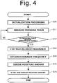
- Fig. 4 is a flow chart illustrating a general outline of the operational procedure of the control unit 60.
- the control unit 60 executes a variety of initialization processing after the power supply is turned on in step S10.
- the control unit 60 starts the measurement of a pressing force in step S11.
- the pressing force measuring means 64 measures the pressing force on the basis of an output from a bridge circuit connected to the pressing force detection unit 50 and stores the pressing force in the RAM or the like.
- the control unit 60 determines if the measured pressing force falls within a preset appropriate range in step S12.
- the pressing force determination means 66 determines if the measured pressing force falls within the appropriate range by comparing the value of the measured pressing force with the upper limit value and the lower limit value of the appropriate pressing force range stored in the ROM or the like. When the measured pressing force falls within the appropriate range, the procedure proceeds to step S13. When the measured pressing force falls outside the appropriate range, the procedure returns to step S11 to measure the pressing force again.
- step S13 the control unit 60 starts to measure a moisture amount.
- the measurement starting means 68 causes the moisture amount measuring means 62 to start the moisture amount measurement on the basis of the determination result of the pressing force determination means 66.
- the measurement starting means 68 controls the sound output unit 100 so as to output notification sound for informing about the start of the moisture amount measurement and also controls the display unit 90 so as to display that the moisture amount is being measured.
- the control unit 60 obtains a resonance frequency in the sensor 32 in step S14.
- the moisture amount measuring means 62 controls the oscillation circuit so as to search for the resonance frequency in the sensor 32 and stores the obtained resonance frequency in the RAM or the like.
- the control unit 60 derives the moisture amount on the basis of the obtained resonance frequency in step S15.
- the moisture amount measuring means 62 derives the moisture amount by comparing the obtained resonance frequency with a table stored in the ROM or the like.
- the control unit 60 stores the derived moisture amount in the RAM or the like and causes the display unit 90 to display the derived moisture amount in step S16.
- the moisture amount measuring means 62 stores the derived moisture amount in the RAM or the like.
- the moisture amount measuring means 62 controls the sound output unit 100 so as to output notification sound for informing about the completion of the moisture amount measurement and also controls the display unit 90 so as to display the derived moisture amount.
- the measuring device 1 of this embodiment allows the moisture amount detecting unit 30 to be easily abutted against the measurement site 200 with an appropriate pressing force without complicating the structure in the vicinity of the moisture amount detecting unit 30. Moreover, since moisture amount measurement is started after the pressing force is determined to fall within the appropriate range, highly accurate measurement can be performed irrespective of the proficiency level of a user.
- the measurement of the pressing force and the determining if the pressing force falls within the appropriate range may be performed. If the pressing force falls outside the appropriate range during the search, the sound output unit 100 may be controlled so as to output the notification sound for informing that the pressing force falls outside the appropriate range. Also, the search for the resonance frequency may be stopped and the procedure may be returned to step S11. In other words, measurement stopping means for stopping moisture amount measurement when the pressing force detected by the pressing force detection unit 50 falls outside the appropriate range may be provided as a functional configuration of the control unit 60.
- FIGs. 5(a) to 5(c) are schematic front views illustrating examples in other forms of the measuring device 1.
- Fig. 5(a) illustrates an example of a case where the swing member 20 is configured to be detachable from the main body 10.
- the swing member 20 may be configured to be detachable from the main body 10 together with the moisture amount detection unit 30.
- the sensor 32 and the control unit 60 may be electrically connected to each other via a suitable connection terminal.
- the moisture amount detection unit 30 and the swing member 20 can be removed from the main body 10, so that they can be easily washed and sterilized, for example.
- the moisture amount detection unit 30 and the swing member 20 can be made disposable. This makes it possible to keep the hygienic state of the measuring device 1 in a more appropriate state.
- the biasing member 40 and the pressing force detection unit 50 are provided on the main body 10 side by providing the swing member 20. This makes it possible to achieve extremely easy washing and sterilization of the portion removed from the main body 10 and to keep the cost low when the moisture amount detection unit 30 and the swing member 20 are made disposable.
- the cover 110 may be omitted by covering the surface of the sensor 32 with a suitable insulating resin, for example, and the moisture amount detection unit 30 may directly be abutted against the contact site to measure a moisture amount.
- the measuring device 1 of this embodiment can keep an appropriate hygienic condition with low cost not only when the moisture amount detection unit 30 is indirectly abutted against the measurement site via the cover 110 but also when the moisture amount detection unit 30 is directly abutted against the measurement site.
- Fig. 5(b) is a schematic front view illustrating an example of a case where the swing member 20 is segmented and a segmented part is configured to be detachable.
- the swing member 20 may be comprised of two parts: a fixed part 24 and a detachable part 26.
- the detachable part 26 may be configured to be detachable from the fixed part 24 and the main body 10 together with the moisture amount detection unit 30.
- the removable part can be, in some cases, detached more easily than the case where the entire swing member 20 is made detachable.
- Fig. 5(c) is a schematic front view illustrating an example of a case where the moisture amount detection unit 30 is formed in a generally flat plate shape smoothly connected to the swing member 20.
- the biasing member 40 and the pressing force detection unit 50 can be disposed on the main body 10 side in this embodiment. This provides a high flexibility in the shape in the vicinity of the moisture amount detection unit 30, and therefore such an extremely simple and compact shape can be employed.
- all or part of the swing member 20 may be configured to be detachable from the main body 10 together with the moisture amount detection unit 30 also in this case.
- FIGS. 6(a) and 6(b) are schematic front views of the intraoral moisture measuring device 2 according to this embodiment.
- the intraoral moisture measuring device 2 (hereinafter simply referred to as the measuring device 2) is obtained by adding a support member 120 for supporting a measurement site from its rear side, i.e., the side opposite to a moisture amount detection unit 30, to the configuration of the measuring device 1 of the first embodiment.
- a lip, a tongue, a cheek, or the like is interposed between the moisture amount detection unit 30 and the support member 120, and this allows the moisture amount detection unit 30 to be surely and stably abutted against the measurement site positioned therebetween.
- a swing member 20 of this embodiment is constituted by: a slightly-curved fixed part 24 positioned closer to a main body 10; and a detachable part 26 detachably attached to the fixed part 24 and provided with the moisture amount detection unit 30 on the tip side thereof.
- the swing member 20 also includes an operation unit 28 extended on the side opposite to the moisture amount detection unit 30 with respect to a swing shaft 14. By operating the operation unit 28 with the index finger or thumb of a hand holding the main body 10, the swing member 20 can be easily swung.
- an engagement member 130 for fixing the detachable part 26 is disposed inside the fixed part 24 of the swing member 20.
- the engagement member 130 is made of a suitable metal capable of elastic deformation, for example.
- the support member 120 is detachably attached to an extended part 18 extended in a slightly curved manner from the main body 10 under the fixed part 24 of the swing member 20.
- the tip of the support member 120 is provided with a protrusion 122 at a position facing the moisture amount detection unit 30.
- an engagement member 132 for fixing the support member 120 is disposed inside the extended part 18.
- the engagement member 132 is made of a suitable metal capable of elastic deformation, for example, as with the engagement member 130.
- the detachable part 26 of the swing member 20 and the support member 120 project so as to be approximately parallel to each other in a direction oblique to the longitudinal direction of the main body 10.
- the moisture amount detection unit 30 and the tip of the support member 120 are disposed at positions easier to interpose a lip, a tongue, a cheek, or the like therebetween when the main body 10 is held by a user.
- Fig. 7(a) is a schematic front view of the detachable part 26.
- Fig. 7(b) is a schematic bottom view of the detachable part 26.
- Fig. 7(c) is a schematic rear view of the detachable part 26.
- the detachable part 26 is formed in a generally rectangular plate shape with a rounded tip.
- a tip portion of a front surface 26a of the detachable part 26 is the moisture amount detection unit 30 and provided with a first electrode 36 and a second electrode 38.
- two connection terminals 26b to be connected with terminals on the fixed part 24 side are provided on the base end side of the front surface 26a.
- two wirings 26c connecting the first electrode 36 and the second electrode 38 with the two connection terminals 26b, respectively, are provided on the front surface 26a.
- a strengthening rib 26e for increasing bending rigidity and an engagement groove 26f for engaging with the engagement member 130 are provided on a rear surface 26d of the detachable part 26.
- the first electrode 36, the second electrode 38, the connection terminals 26b, and the wirings 26c are formed by electrically-conductive thin films disposed on the front surface 26a. Moreover, the first electrode 36, the second electrode 38, and the wirings 26c are covered with an insulating layer, and thus the moisture amount detection unit 30 can be brought into direct contact with the measurement site. Furthermore, the wirings 26c are covered with a shield 26g made of an electrically-conductive thin film via the insulating layer therebetween. This prevents capacitance between the two wirings 26c from affecting the measurement of a moisture amount.
- the detachable part 26 of this embodiment functions as part of the swing member 20 by extending the substrate 34 of the conventional sensor 32 in the first embodiment toward the main body 10. Furthermore, in this embodiment, providing the shield 26g makes it possible to maintain accuracy in the measurement of a moisture amount while the wirings 26c are formed by the electrically-conductive thin films. This allows the moisture amount detection unit 30 and the detachable part 26 to be configured extremely simply and inexpensively. Thus, the cost when the detachable part 26 is made disposable can be reduced.
- a suitable material such as a resin or ceramic, for example, can be employed as a material for the detachable part 26.
- a suitable material such as copper or aluminum, for example, may be employed as a material for the electrically-conductive thin films forming the first electrode 36, the second electrode 38, and the like.
- the insulating layer with which the first electrode 36, the second electrode 38, and the wirings 26c are covered may be formed by coating of an ultraviolet curable resin, for example.
- such an insulating layer may be formed by a resin film, for example, disposed on the first electrode 36, the second electrode 38, and the wirings 26c.
- a suitable material such as copper or aluminum, for example, can be employed as a material for the electrically-conductive thin film forming the shield 26g.
- an additional insulating resin film for example, may be disposed between the insulating layer and the shield 26g so as to adjust the distance between the wirings 26c and the shield 26g and thereby optimize the shielding effect of the shield 26g.
- Fig. 7(d) is a schematic front view of the support member 120.
- Fig. 7(e) is a schematic bottom view of the support member 120.
- Fig. 7(f) is a schematic rear view of the support member 120.
- the support member 120 is formed in a generally rectangular plate shape with a rounded tip as with the detachable part 26.
- the protrusion 122 having a generally cylindrical shape is provided at the tip of a front surface 120a of the support member 120.
- a strengthening rib 124 for increasing bending rigidity and an engagement groove 126 for engaging with the engagement member 132 are provided on a rear surface 120b of the support member 120.
- the support member 120 is provided with the protrusion 122 having a generally cylindrical shape.
- the measurement site is supported from its rear side by an upper surface 122a, having a generally flat shape, of the protrusion 122.
- This allows the moisture amount detection unit 30 to be abutted against the measurement site in a generally uniform and stable manner.
- the support member 120 and the detachable part 26 are formed in approximately the same shape in this embodiment. This achieves the commonality of the parts, thereby further reducing the cost of the detachable part 26 and the support member 120.
- Fig. 8(a) is a schematic front view illustrating a state when the detachable part 26 and the support member 120 are being attached.
- Fig. 8(b) is a schematic front view illustrating a state when the detachable part 26 and the support member 120 are being removed.
- the detachable part 26 is inserted, from the base end side thereof, into the fixed part 24 along a guiding member (not shown) with the front surface 26a facing the support member 120 as shown in Fig. 8(a) .
- the engagement member 130 elastically deformed by the insertion of the detachable part 26 is fitted into and engaged with the engagement groove 26f.
- the detachable part 26 is thereby fixed to the fixed part 24.
- connection terminals 26b are connected to the terminals (not shown) in the fixed part 24. This achieves electrical connection between the moisture amount detection unit 30 and the control unit 60. In other words, simply by inserting the detachable part 26 into the fixed part 24 in the longitudinal direction thereof, the detachable part 26 can be attached to the fixed part 24 in an extremely easy manner.
- the support member 120 is inserted, from the base end side thereof, into the extended part 18 along a guiding member (not shown) with the front surface 120a facing the detachable part 26 and the engagement member 132 is then engaged with the engagement groove 126.
- the support member 120 can be removed from the main body 10 simply by pulling the support member 120 toward the tip side thereof.
- the detachable part 26 and the support member 120 which are the parts to be in contact with a subject to be measured, can be replaced in an extremely easy manner in this embodiment.
- an appropriate hygienic condition can be surely maintained while measuring intraoral moisture in a simple and prompt manner.
- FIGs. 9(a) to 9(c) are schematic views illustrating the method of using the measuring device 2.
- the detachable part 26 and the support member 120 newly prepared or the detachable part 26 and the support member 120 washed and sterilized are first attached to the fixed part 24 and the main body 10.
- an operation button 80 is operated to turn on the power supply of the measuring device 2. This starts the measurement of pressing force by pressing force measuring means 64.
- the operation unit 28 is pressed to swing the swing member 20 and thereby set the moisture amount detection unit 30 apart from the support member 120 as shown in Fig. 9(a) .
- the measurement of a moisture amount is prevented from starting by causing the pressing force by the biasing member 40 to exceed the upper limit of the appropriate range.
- the measuring device 2 is disposed such that a lip, for example, of a subject to be measured is positioned between the moisture amount detection unit 30 and the support member 120 to cause the moisture amount detection unit 30 to face a measurement site 200 as shown in Fig. 9(b) .
- the moisture amount detection unit 30 is abutted against the measurement site 200 and the protrusion 122 of the support member 120 is abutted against a rear side 202 of the measurement site 200.
- the pressing force to the measurement site 200 by the moisture amount detection unit 30 thereby falls within the appropriate range, and the measurement of a moisture amount is thus started.
- an adjustment mechanism for adjusting the biasing force of the biasing member 40 may be provided and the pressing force may be adjusted by this adjustment mechanism.
- the pressing force may be adjusted by replacing the detachable part 26 and the support member 120 with those having different shapes depending on a thickness around the measurement site 200, for example.
- the moisture amount detection unit 30 can be stably abutted against the measurement site 200 with an appropriate pressing force even in an unstable portion such as a lip or a tongue.
- the measurement of a moisture amount in such a measurement site 200 can be performed with high accuracy.
- the pressing force can be stably enhanced by the support member 120. This allows for the measurement of a moisture amount at a position deeper than that in the conventional techniques.
- the measuring device 2 of this embodiment allows for the measurement of a moisture amount in a labial minor salivary gland, which is difficult to achieve with the conventional techniques.
- the diagnosis of the Sjogren syndrome can be simplified.
- the measuring devices 1 and 2 of the aforementioned embodiments each include: the swing member 20 that swings with respect to the main body 10 about the predetermined swing center C; the moisture amount detection unit 30 provided at the tip of the swing member 20 for detecting a moisture amount by being directly or indirectly abutted against the measurement site 200 in a mouth; and the biasing member 40 for biasing the swing member 20 in one of the swing directions.
- the combination of the swing member 20 and the biasing member 40 allows the moisture amount detection unit 30 to be abutted against the measurement site 200 with an appropriate pressing force.
- a moisture amount can be measured with high accuracy.
- the combination of the swing member 20 and the biasing member 40 allows for the optimization of the pressing force without complicating the structure in the vicinity of the moisture amount detection unit 30. This facilitates, for example, the washing and sterilization of the moisture amount detection unit 30 and its adjacent part.
- the moisture amount detection unit 30 and its adjacent part can achieve a reduced cost and can therefore be easily made disposable.
- the swing center C is disposed in the main body 10.
- the biasing member 40 can be disposed away from the moisture amount detection unit 30. Consequently, the structure around the moisture amount detection unit 30 can be simplified, and thus easily washed, sterilized, or made disposable.
- the measuring devices 1 and 2 each include the pressing force detection unit 50 for detecting a pressing force to the measurement site 200 by the moisture amount detection unit 30.
- the pressing force detection unit 50 for detecting a pressing force to the measurement site 200 by the moisture amount detection unit 30.
- the pressing force detection unit 50 is disposed inside the main body 10. With such a configuration, the structure around the moisture amount detection unit 30 can be simplified, and thus easily washed, sterilized, or made disposable.
- the measuring devices 1 and 2 each include the control unit 60 that controls the moisture amount detection unit 30 and the pressing force detection unit 50.
- the control unit 60 includes the pressing force determination means 66 for determining if the pressing force detected by the pressing force detection unit 50 falls within the appropriate range.
- control unit 60 includes the measurement starting means 68 that starts moisture amount measurement when the pressing force detected by the pressing force detection unit 50 falls within the appropriate range.
- control unit 60 may include the measurement stopping means for stopping the moisture amount measurement when the pressing force detected by the pressing force detection unit 50 falls outside the appropriate range.
- the swing member 20 may be configured to be detachable from the main body 10 together with the moisture amount detection unit 30.
- the moisture amount detection unit 30 and its adjacent part can be easily washed, sterilized, or made disposable.
- an appropriate hygienic condition can be maintained.
- the swing member 20 in the measuring device 2 includes the detachable part 26 which is detachable from the main body 10 together with the moisture amount detection unit 30.
- the detachable part 26 is provided with the first electrode 36 and the second electrode 38 included in the moisture amount detection unit 30 and the wirings 26c connected to the first electrode 36 and the second electrode 38.
- the first electrode 36, the second electrode 38, and the wirings 26c are formed by the electrically-conductive thin films disposed in the detachable part 26.
- the wirings 26c in the measuring device 2 are covered with the shield 26g formed by the electrically-conductive thin film.
- the wirings 26c can be prevented from affecting the measurement of a moisture amount even when the wirings 26c are formed simply and inexpensively by the electrically-conductive thin films. Thus, measurement accuracy can be maintained.
- the measuring device 2 includes the support member 120 for supporting the rear side 202 of the measurement site 200. This allows the moisture amount detection unit 30 to be stably abutted against the measurement site 200 with an appropriate pressing force even in an unstable portion. Moreover, since a pressing force can be stably enhanced, moisture amount measurement at such a position that the measurement has been difficult to achieve with the conventional techniques can be carried out.
- the support member 120 includes the protrusion 122 protruded toward the rear side 202 of the measurement site 200.
- the protrusion 122 includes the generally flat-shaped surface (the upper surface 122a) to be abutted against the rear side 202 of the measurement site 200. This allows the moisture amount detection unit 30 to be abutted against the measurement site 200 in a generally uniform and stable manner. Thus, a moisture amount can be measured with high accuracy.
- the intraoral moisture measuring device of the present invention is not limited to the aforementioned embodiments. It is to be understood that various modifications are possible without departing from the scope of the present invention.
- the shapes of the components in the measuring devices 1 and 2, such as the main body 10 and the swing member 20, are not limited to the shapes described in the aforementioned embodiments, and other shapes can be employed as desired.
- the biasing member 40 may be a coiled spring or a torsion spring, for example, without being limited to the flat spring.
- the pressing force detection unit 50 may be provided in a region other than the biasing member 40.
- the configuration of the second embodiment e.g., the configuration of the detachable part 26, may be applied to the first embodiment.
- the pressing force detection unit 50, the pressing force measuring means 64, and the pressing force determination means 66 may be omitted.
- a measurement starting button may be further provided in the main body 10 so that moisture amount measurement is started by the operation of the measurement starting button by a user.
- the measuring devices 1 and 2 each may be configured to include a communication unit for communicating with an external computer or the like and to be capable of transmitting stored measurement results, for example, to the external computer or the like.
- the control unit 60, the power supply unit 70, the operation button 80, the display unit 90, and the sound output unit 100 may be provided outside the main body 10, and these may be configured by an existing computer.
- the intraoral moisture measuring device can be used in the fields such as various types of oral care and various diagnoses relating to xerostomia in medical institutions or the like.
Claims (9)
- Dispositif de mesure d'humidité intrabuccale (1) comprenant :un élément d'oscillation (20) qui est adapté pour osciller par rapport à un corps principal (10) autour d'un centre d'oscillation (14) prédéterminé qui est disposé dans le corps principal (10) ;une unité de détection de quantité d'humidité (30) prévue au niveau d'une pointe de l'élément d'oscillation (20), pour détecter une quantité d'humidité en venant directement ou indirectement en butée contre un site de mesure dans une bouche ;un élément de sollicitation (40) pour solliciter l'élément d'oscillation (20) dans l'une des directions d'oscillation, etune unité de détection de force de pression (50) pour détecter une force de pression sur le site de mesure par l'unité de détection de quantité d'humidité (30),caractérisé en ce que :l'unité de détection de force de pression (50) est disposée à l'intérieur du corps principal (10).
- Dispositif de mesure d'humidité intrabuccale (1) selon la revendication 1, comprenant une unité de commande (60) pour commander l'unité de détection de quantité d'humidité (30) et l'unité de détection de force de pression (50), et dans lequel :l'unité de commande (60) comprend un moyen de détermination de force de pression (66) pour déterminer si la force de pression détectée par l'unité de détection de force de pression (50) est dans une plage appropriée.
- Dispositif de mesure d'humidité intrabuccale (1) selon la revendication 2, dans lequel l'unité de commande (60) comprend un moyen de déclenchement de mesure (68) qui déclenche la mesure de quantité d'humidité lorsque la force de pression détectée par l'unité de détection de force de pression (50) est dans la plage appropriée.
- Dispositif de mesure d'humidité intrabuccale (1) selon la revendication 2 ou 3, dans lequel l'unité de commande (60) comprend un moyen d'arrêt de mesure pour arrêter la mesure de quantité d'humidité lorsque la force de pression détectée par l'unité de détection de force de pression (50) est hors de la plage appropriée.
- Dispositif de mesure d'humidité intrabuccale (1) selon l'une quelconque des revendications 1 à 4, dans lequel l'élément d'oscillation (20) est configuré pour être au moins partiellement détachable du corps principal (10) conjointement avec l'unité de détection de quantité d'humidité (30).
- Dispositif de mesure d'humidité intrabuccale (1) selon la revendication 5, dans lequel :l'élément d'oscillation (20) comprend une partie détachable (26) qui peut être détachée du corps principal (10) conjointement avec l'unité de détection de quantité d'humidité (30),la partie détachable (26) est prévue avec une première électrode (36) et une seconde électrode (38) comprise dans l'unité de détection de quantité d'humidité (30) et des câblages (26c) raccordés à la première électrode (36) et à la seconde électrode (38), etla première électrode (36), la seconde électrode (38) et les câblages (26c) sont formés par des films fins électriquement conducteurs disposés dans la partie détachable (26).
- Dispositif de mesure d'humidité intrabuccale (1) selon la revendication 6, dans lequel les câblages (26c) sont recouverts avec une protection (26g) constituée par un film fin électriquement conducteur.
- Dispositif de mesure d'humidité intrabuccale (1) selon l'une quelconque des revendications 1 à 7, comprenant un élément de support (120) pour supporter un côté arrière du site de mesure.
- Dispositif de mesure d'humidité intrabuccale (1) selon la revendication 8, dans lequel :l'élément de support (120) comprend une saillie (122) faisant saillie vers le côté arrière du site de mesure, etla saillie (122) comprend une surface de forme généralement plate pour venir en butée contre le côté arrière du site de mesure.
Applications Claiming Priority (1)
| Application Number | Priority Date | Filing Date | Title |
|---|---|---|---|
| PCT/JP2014/053846 WO2015125222A1 (fr) | 2014-02-19 | 2014-02-19 | Dispositif de mesure d'humidité intrabuccale |
Publications (3)
| Publication Number | Publication Date |
|---|---|
| EP2995251A1 EP2995251A1 (fr) | 2016-03-16 |
| EP2995251A4 EP2995251A4 (fr) | 2016-05-11 |
| EP2995251B1 true EP2995251B1 (fr) | 2017-05-17 |
Family
ID=53877760
Family Applications (1)
| Application Number | Title | Priority Date | Filing Date |
|---|---|---|---|
| EP14882866.8A Active EP2995251B1 (fr) | 2014-02-19 | 2014-02-19 | Dispositif de mesure d'humidité intrabuccale |
Country Status (4)
| Country | Link |
|---|---|
| US (2) | US10219735B2 (fr) |
| EP (1) | EP2995251B1 (fr) |
| JP (1) | JP5839213B1 (fr) |
| WO (1) | WO2015125222A1 (fr) |
Families Citing this family (19)
| Publication number | Priority date | Publication date | Assignee | Title |
|---|---|---|---|---|
| JP6944941B2 (ja) * | 2016-02-02 | 2021-10-06 | エスゾーン メディカル プライベート リミテッドSzone Medical Pte. Ltd. | 体液平衡及び/又は電解質平衡を検出するためのデバイス |
| DE102016123345B3 (de) * | 2016-12-02 | 2018-05-09 | Tilman Kraus | Vorrichtung zum Trocknen von Zahn- oder Knochenoberflächen |
| US10736612B2 (en) | 2016-12-14 | 2020-08-11 | Boka Sciences, Inc. | Salvia assessing method, device, and system |
| JP7101944B2 (ja) * | 2018-03-13 | 2022-07-19 | 島根県 | 肌状態測定装置 |
| CN113167605B (zh) * | 2019-02-04 | 2023-11-28 | 株式会社村田制作所 | 罩 |
| JP7287452B2 (ja) * | 2019-02-18 | 2023-06-06 | 株式会社村田製作所 | 測定器及び口腔内水分測定器 |
| WO2020171029A1 (fr) * | 2019-02-19 | 2020-08-27 | 株式会社村田製作所 | Instrument de mesure |
| WO2020179691A1 (fr) * | 2019-03-01 | 2020-09-10 | 株式会社村田製作所 | Instrument de mesure |
| JP7279787B2 (ja) * | 2019-06-14 | 2023-05-23 | 株式会社村田製作所 | 測定器 |
| JP2021083482A (ja) * | 2019-11-25 | 2021-06-03 | 株式会社村田製作所 | 口腔内測定装置及び口腔内測定システム |
| WO2021152925A1 (fr) * | 2020-01-30 | 2021-08-05 | 株式会社村田製作所 | Appareil de mesure d'informations biométriques et système de mesure d'informations biométriques |
| WO2021152926A1 (fr) * | 2020-01-30 | 2021-08-05 | 株式会社村田製作所 | Appareil de mesure intrabuccal et système de mesure intrabuccal |
| CN113331786A (zh) * | 2020-02-17 | 2021-09-03 | 株式会社村田制作所 | 测定装置以及测定系统 |
| JP7052836B2 (ja) * | 2020-08-06 | 2022-04-12 | 株式会社村田製作所 | 測定装置及び測定システム |
| JP6750749B1 (ja) * | 2020-02-17 | 2020-09-02 | 株式会社村田製作所 | 測定装置及び測定システム |
| JP7354932B2 (ja) * | 2020-06-08 | 2023-10-03 | 株式会社村田製作所 | 口腔用治具 |
| JP7272324B2 (ja) * | 2020-06-10 | 2023-05-12 | 株式会社村田製作所 | 口腔用治具 |
| CN115666379A (zh) | 2020-06-19 | 2023-01-31 | 株式会社村田制作所 | 口腔器具 |
| WO2023037793A1 (fr) * | 2021-09-10 | 2023-03-16 | 株式会社村田製作所 | Capteur de capacité et dispositif de mesure |
Family Cites Families (14)
| Publication number | Priority date | Publication date | Assignee | Title |
|---|---|---|---|---|
| JPS61140830A (ja) * | 1984-12-13 | 1986-06-27 | Matsushita Electric Works Ltd | 舌下型体温計 |
| SE501585C2 (sv) * | 1992-08-11 | 1995-03-20 | Swedish Sophisticated Export I | Anordning för att fixera föremål såsom mätorgan, sensor, sond, slang eller liknande i mun, näsa eller annan öppning hos en människa eller annan individ |
| JPH07327937A (ja) * | 1994-06-07 | 1995-12-19 | Kitazato Supply:Kk | 口腔内の表面弾性測定器具および表面弾性測定装置 |
| JP2003169788A (ja) | 2001-12-05 | 2003-06-17 | Matsushita Electric Ind Co Ltd | 肌水分量測定装置 |
| EP1543768B1 (fr) | 2002-09-24 | 2012-12-26 | ICST Corporation | Procede et instrument permettant de mesurer la teneur en eau de la bouche |
| JP2005205041A (ja) | 2004-01-23 | 2005-08-04 | Horiba Ltd | 接触式測定器のセンサ部保持構造 |
| JP2006122347A (ja) * | 2004-10-28 | 2006-05-18 | Life:Kk | 口腔水分計 |
| JP5646939B2 (ja) * | 2010-09-29 | 2014-12-24 | テルモ株式会社 | 水分計 |
| EP2687155A4 (fr) * | 2011-03-15 | 2014-09-10 | Terumo Corp | Dispositif de mesure d'humidité et dispositif de mesure d'humidité corporelle |
| JP2013066565A (ja) * | 2011-09-21 | 2013-04-18 | Terumo Corp | 体内水分計及びその制御方法 |
| JP5917911B2 (ja) * | 2011-12-27 | 2016-05-18 | テルモ株式会社 | 体内水分計および表示制御方法 |
| US20150031964A1 (en) * | 2012-02-22 | 2015-01-29 | Aclaris Medical, Llc | Physiological signal detecting device and system |
| JP2013195118A (ja) * | 2012-03-16 | 2013-09-30 | Life Co Ltd | 静電容量式水分センサ、水分測定器 |
| WO2014113897A1 (fr) * | 2013-01-28 | 2014-07-31 | Sensimat Systems Inc. | Système à stations multiples pour la surveillance et l'analyse d'une escarre de décubitus |
-
2014
- 2014-02-19 US US14/896,675 patent/US10219735B2/en active Active
- 2014-02-19 WO PCT/JP2014/053846 patent/WO2015125222A1/fr active Application Filing
- 2014-02-19 EP EP14882866.8A patent/EP2995251B1/fr active Active
- 2014-02-19 JP JP2015527694A patent/JP5839213B1/ja active Active
-
2019
- 2019-01-17 US US16/250,261 patent/US11529093B2/en active Active
Also Published As
| Publication number | Publication date |
|---|---|
| WO2015125222A1 (fr) | 2015-08-27 |
| US20190183407A1 (en) | 2019-06-20 |
| US20160135728A1 (en) | 2016-05-19 |
| EP2995251A4 (fr) | 2016-05-11 |
| JP5839213B1 (ja) | 2016-01-06 |
| US11529093B2 (en) | 2022-12-20 |
| JPWO2015125222A1 (ja) | 2017-03-30 |
| US10219735B2 (en) | 2019-03-05 |
| EP2995251A1 (fr) | 2016-03-16 |
Similar Documents
| Publication | Publication Date | Title |
|---|---|---|
| US11529093B2 (en) | Intraoral moisture measuring device | |
| JP5624984B2 (ja) | 連続分析装置 | |
| US9433370B2 (en) | Moisture meter | |
| EP2886050B1 (fr) | Humidimètre corporel | |
| WO2005092182A1 (fr) | Dispositif de mesure d’informations biologiques | |
| WO2012097505A1 (fr) | Appareil de mesure | |
| TW202133805A (zh) | 可穿戴器件、可穿戴器件形成方法、及連續分析物監測系統中重複使用可穿戴器件的傳送器單元的方法 | |
| KR101276363B1 (ko) | 통증 모니터링 장치 | |
| US20210338096A1 (en) | Measuring instrument | |
| WO2005092180A1 (fr) | Dispositif de mesure d’informations biologiques | |
| US20130261407A1 (en) | Moisture meter | |
| US20090096748A1 (en) | Input device with physiological measuring function | |
| JP4457192B2 (ja) | ランセット一体型測定装置 | |
| ES2753356T3 (es) | Un procedimiento y un dispositivo para determinar un nivel de glucosa en líquido corporal de un paciente, y un producto de programa informático | |
| US20110251510A1 (en) | Respiration sensor for an infant feeding performance measurement device | |
| WO2020171005A1 (fr) | Instrument de mesure | |
| KR20090087521A (ko) | 생체 신호 계측용 휴대용 장치 | |
| JP5859846B2 (ja) | 体内水分計 | |
| CN210408423U (zh) | 成分分析设备 | |
| RU214859U1 (ru) | Устройство для измерения электрохимических потенциалов в полости рта | |
| WO2014024228A1 (fr) | Instrument de mesure de l'eau du corps et procédé de fabrication associé | |
| KR20210015398A (ko) | 자동혈압계가 구비된 토니켓 | |
| JP2006167269A (ja) | 生体情報測定方法および生体情報測定装置 | |
| KR20200099967A (ko) | 기능적 근적외선 분광기의 머리 장착용 센서 장치 | |
| JP2016095207A (ja) | センサカートリッジおよび糖濃度測定装置 |
Legal Events
| Date | Code | Title | Description |
|---|---|---|---|
| PUAI | Public reference made under article 153(3) epc to a published international application that has entered the european phase |
Free format text: ORIGINAL CODE: 0009012 |
|
| 17P | Request for examination filed |
Effective date: 20151208 |
|
| AK | Designated contracting states |
Kind code of ref document: A1 Designated state(s): AL AT BE BG CH CY CZ DE DK EE ES FI FR GB GR HR HU IE IS IT LI LT LU LV MC MK MT NL NO PL PT RO RS SE SI SK SM TR |
|
| AX | Request for extension of the european patent |
Extension state: BA ME |
|
| A4 | Supplementary search report drawn up and despatched |
Effective date: 20160407 |
|
| RIC1 | Information provided on ipc code assigned before grant |
Ipc: A61B 5/00 20060101ALI20160401BHEP Ipc: A61B 5/05 20060101AFI20160401BHEP |
|
| 17Q | First examination report despatched |
Effective date: 20160421 |
|
| REG | Reference to a national code |
Ref country code: DE Ref legal event code: R079 Ref document number: 602014010038 Country of ref document: DE Free format text: PREVIOUS MAIN CLASS: A61B0005050000 Ipc: A61B0005053000 |
|
| GRAP | Despatch of communication of intention to grant a patent |
Free format text: ORIGINAL CODE: EPIDOSNIGR1 |
|
| RIC1 | Information provided on ipc code assigned before grant |
Ipc: A61B 5/00 20060101ALI20161031BHEP Ipc: A61B 5/053 20060101AFI20161031BHEP |
|
| DAX | Request for extension of the european patent (deleted) | ||
| INTG | Intention to grant announced |
Effective date: 20161201 |
|
| GRAS | Grant fee paid |
Free format text: ORIGINAL CODE: EPIDOSNIGR3 |
|
| GRAA | (expected) grant |
Free format text: ORIGINAL CODE: 0009210 |
|
| AK | Designated contracting states |
Kind code of ref document: B1 Designated state(s): AL AT BE BG CH CY CZ DE DK EE ES FI FR GB GR HR HU IE IS IT LI LT LU LV MC MK MT NL NO PL PT RO RS SE SI SK SM TR |
|
| REG | Reference to a national code |
Ref country code: GB Ref legal event code: FG4D |
|
| REG | Reference to a national code |
Ref country code: CH Ref legal event code: EP |
|
| REG | Reference to a national code |
Ref country code: IE Ref legal event code: FG4D |
|
| REG | Reference to a national code |
Ref country code: AT Ref legal event code: REF Ref document number: 893705 Country of ref document: AT Kind code of ref document: T Effective date: 20170615 |
|
| REG | Reference to a national code |
Ref country code: DE Ref legal event code: R096 Ref document number: 602014010038 Country of ref document: DE |
|
| REG | Reference to a national code |
Ref country code: NL Ref legal event code: MP Effective date: 20170517 |
|
| REG | Reference to a national code |
Ref country code: LT Ref legal event code: MG4D |
|
| REG | Reference to a national code |
Ref country code: AT Ref legal event code: MK05 Ref document number: 893705 Country of ref document: AT Kind code of ref document: T Effective date: 20170517 |
|
| PG25 | Lapsed in a contracting state [announced via postgrant information from national office to epo] |
Ref country code: AT Free format text: LAPSE BECAUSE OF FAILURE TO SUBMIT A TRANSLATION OF THE DESCRIPTION OR TO PAY THE FEE WITHIN THE PRESCRIBED TIME-LIMIT Effective date: 20170517 Ref country code: NO Free format text: LAPSE BECAUSE OF FAILURE TO SUBMIT A TRANSLATION OF THE DESCRIPTION OR TO PAY THE FEE WITHIN THE PRESCRIBED TIME-LIMIT Effective date: 20170817 Ref country code: FI Free format text: LAPSE BECAUSE OF FAILURE TO SUBMIT A TRANSLATION OF THE DESCRIPTION OR TO PAY THE FEE WITHIN THE PRESCRIBED TIME-LIMIT Effective date: 20170517 Ref country code: GR Free format text: LAPSE BECAUSE OF FAILURE TO SUBMIT A TRANSLATION OF THE DESCRIPTION OR TO PAY THE FEE WITHIN THE PRESCRIBED TIME-LIMIT Effective date: 20170818 Ref country code: ES Free format text: LAPSE BECAUSE OF FAILURE TO SUBMIT A TRANSLATION OF THE DESCRIPTION OR TO PAY THE FEE WITHIN THE PRESCRIBED TIME-LIMIT Effective date: 20170517 Ref country code: LT Free format text: LAPSE BECAUSE OF FAILURE TO SUBMIT A TRANSLATION OF THE DESCRIPTION OR TO PAY THE FEE WITHIN THE PRESCRIBED TIME-LIMIT Effective date: 20170517 Ref country code: HR Free format text: LAPSE BECAUSE OF FAILURE TO SUBMIT A TRANSLATION OF THE DESCRIPTION OR TO PAY THE FEE WITHIN THE PRESCRIBED TIME-LIMIT Effective date: 20170517 |
|
| PG25 | Lapsed in a contracting state [announced via postgrant information from national office to epo] |
Ref country code: PL Free format text: LAPSE BECAUSE OF FAILURE TO SUBMIT A TRANSLATION OF THE DESCRIPTION OR TO PAY THE FEE WITHIN THE PRESCRIBED TIME-LIMIT Effective date: 20170517 Ref country code: SE Free format text: LAPSE BECAUSE OF FAILURE TO SUBMIT A TRANSLATION OF THE DESCRIPTION OR TO PAY THE FEE WITHIN THE PRESCRIBED TIME-LIMIT Effective date: 20170517 Ref country code: LV Free format text: LAPSE BECAUSE OF FAILURE TO SUBMIT A TRANSLATION OF THE DESCRIPTION OR TO PAY THE FEE WITHIN THE PRESCRIBED TIME-LIMIT Effective date: 20170517 Ref country code: NL Free format text: LAPSE BECAUSE OF FAILURE TO SUBMIT A TRANSLATION OF THE DESCRIPTION OR TO PAY THE FEE WITHIN THE PRESCRIBED TIME-LIMIT Effective date: 20170517 Ref country code: RS Free format text: LAPSE BECAUSE OF FAILURE TO SUBMIT A TRANSLATION OF THE DESCRIPTION OR TO PAY THE FEE WITHIN THE PRESCRIBED TIME-LIMIT Effective date: 20170517 Ref country code: BG Free format text: LAPSE BECAUSE OF FAILURE TO SUBMIT A TRANSLATION OF THE DESCRIPTION OR TO PAY THE FEE WITHIN THE PRESCRIBED TIME-LIMIT Effective date: 20170817 Ref country code: IS Free format text: LAPSE BECAUSE OF FAILURE TO SUBMIT A TRANSLATION OF THE DESCRIPTION OR TO PAY THE FEE WITHIN THE PRESCRIBED TIME-LIMIT Effective date: 20170917 |
|
| PG25 | Lapsed in a contracting state [announced via postgrant information from national office to epo] |
Ref country code: EE Free format text: LAPSE BECAUSE OF FAILURE TO SUBMIT A TRANSLATION OF THE DESCRIPTION OR TO PAY THE FEE WITHIN THE PRESCRIBED TIME-LIMIT Effective date: 20170517 Ref country code: RO Free format text: LAPSE BECAUSE OF FAILURE TO SUBMIT A TRANSLATION OF THE DESCRIPTION OR TO PAY THE FEE WITHIN THE PRESCRIBED TIME-LIMIT Effective date: 20170517 Ref country code: CZ Free format text: LAPSE BECAUSE OF FAILURE TO SUBMIT A TRANSLATION OF THE DESCRIPTION OR TO PAY THE FEE WITHIN THE PRESCRIBED TIME-LIMIT Effective date: 20170517 Ref country code: DK Free format text: LAPSE BECAUSE OF FAILURE TO SUBMIT A TRANSLATION OF THE DESCRIPTION OR TO PAY THE FEE WITHIN THE PRESCRIBED TIME-LIMIT Effective date: 20170517 Ref country code: SK Free format text: LAPSE BECAUSE OF FAILURE TO SUBMIT A TRANSLATION OF THE DESCRIPTION OR TO PAY THE FEE WITHIN THE PRESCRIBED TIME-LIMIT Effective date: 20170517 |
|
| REG | Reference to a national code |
Ref country code: DE Ref legal event code: R097 Ref document number: 602014010038 Country of ref document: DE |
|
| REG | Reference to a national code |
Ref country code: FR Ref legal event code: PLFP Year of fee payment: 5 |
|
| PG25 | Lapsed in a contracting state [announced via postgrant information from national office to epo] |
Ref country code: IT Free format text: LAPSE BECAUSE OF FAILURE TO SUBMIT A TRANSLATION OF THE DESCRIPTION OR TO PAY THE FEE WITHIN THE PRESCRIBED TIME-LIMIT Effective date: 20170517 Ref country code: SM Free format text: LAPSE BECAUSE OF FAILURE TO SUBMIT A TRANSLATION OF THE DESCRIPTION OR TO PAY THE FEE WITHIN THE PRESCRIBED TIME-LIMIT Effective date: 20170517 |
|
| PLBE | No opposition filed within time limit |
Free format text: ORIGINAL CODE: 0009261 |
|
| STAA | Information on the status of an ep patent application or granted ep patent |
Free format text: STATUS: NO OPPOSITION FILED WITHIN TIME LIMIT |
|
| 26N | No opposition filed |
Effective date: 20180220 |
|
| PG25 | Lapsed in a contracting state [announced via postgrant information from national office to epo] |
Ref country code: SI Free format text: LAPSE BECAUSE OF FAILURE TO SUBMIT A TRANSLATION OF THE DESCRIPTION OR TO PAY THE FEE WITHIN THE PRESCRIBED TIME-LIMIT Effective date: 20170517 |
|
| REG | Reference to a national code |
Ref country code: CH Ref legal event code: PL |
|
| PG25 | Lapsed in a contracting state [announced via postgrant information from national office to epo] |
Ref country code: MC Free format text: LAPSE BECAUSE OF FAILURE TO SUBMIT A TRANSLATION OF THE DESCRIPTION OR TO PAY THE FEE WITHIN THE PRESCRIBED TIME-LIMIT Effective date: 20170517 |
|
| REG | Reference to a national code |
Ref country code: IE Ref legal event code: MM4A |
|
| REG | Reference to a national code |
Ref country code: BE Ref legal event code: MM Effective date: 20180228 |
|
| PG25 | Lapsed in a contracting state [announced via postgrant information from national office to epo] |
Ref country code: CH Free format text: LAPSE BECAUSE OF NON-PAYMENT OF DUE FEES Effective date: 20180228 Ref country code: LI Free format text: LAPSE BECAUSE OF NON-PAYMENT OF DUE FEES Effective date: 20180228 Ref country code: LU Free format text: LAPSE BECAUSE OF NON-PAYMENT OF DUE FEES Effective date: 20180219 |
|
| PG25 | Lapsed in a contracting state [announced via postgrant information from national office to epo] |
Ref country code: IE Free format text: LAPSE BECAUSE OF NON-PAYMENT OF DUE FEES Effective date: 20180219 |
|
| PG25 | Lapsed in a contracting state [announced via postgrant information from national office to epo] |
Ref country code: BE Free format text: LAPSE BECAUSE OF NON-PAYMENT OF DUE FEES Effective date: 20180228 |
|
| PG25 | Lapsed in a contracting state [announced via postgrant information from national office to epo] |
Ref country code: MT Free format text: LAPSE BECAUSE OF NON-PAYMENT OF DUE FEES Effective date: 20180219 |
|
| PG25 | Lapsed in a contracting state [announced via postgrant information from national office to epo] |
Ref country code: TR Free format text: LAPSE BECAUSE OF FAILURE TO SUBMIT A TRANSLATION OF THE DESCRIPTION OR TO PAY THE FEE WITHIN THE PRESCRIBED TIME-LIMIT Effective date: 20170517 |
|
| PG25 | Lapsed in a contracting state [announced via postgrant information from national office to epo] |
Ref country code: PT Free format text: LAPSE BECAUSE OF FAILURE TO SUBMIT A TRANSLATION OF THE DESCRIPTION OR TO PAY THE FEE WITHIN THE PRESCRIBED TIME-LIMIT Effective date: 20170517 |
|
| PG25 | Lapsed in a contracting state [announced via postgrant information from national office to epo] |
Ref country code: HU Free format text: LAPSE BECAUSE OF FAILURE TO SUBMIT A TRANSLATION OF THE DESCRIPTION OR TO PAY THE FEE WITHIN THE PRESCRIBED TIME-LIMIT; INVALID AB INITIO Effective date: 20140219 Ref country code: MK Free format text: LAPSE BECAUSE OF NON-PAYMENT OF DUE FEES Effective date: 20170517 Ref country code: CY Free format text: LAPSE BECAUSE OF FAILURE TO SUBMIT A TRANSLATION OF THE DESCRIPTION OR TO PAY THE FEE WITHIN THE PRESCRIBED TIME-LIMIT Effective date: 20170517 |
|
| PG25 | Lapsed in a contracting state [announced via postgrant information from national office to epo] |
Ref country code: AL Free format text: LAPSE BECAUSE OF FAILURE TO SUBMIT A TRANSLATION OF THE DESCRIPTION OR TO PAY THE FEE WITHIN THE PRESCRIBED TIME-LIMIT Effective date: 20170517 |
|
| PGFP | Annual fee paid to national office [announced via postgrant information from national office to epo] |
Ref country code: FR Payment date: 20230220 Year of fee payment: 10 |
|
| PGFP | Annual fee paid to national office [announced via postgrant information from national office to epo] |
Ref country code: GB Payment date: 20230221 Year of fee payment: 10 Ref country code: DE Payment date: 20230227 Year of fee payment: 10 |
|
| PGFP | Annual fee paid to national office [announced via postgrant information from national office to epo] |
Ref country code: DE Payment date: 20240227 Year of fee payment: 11 Ref country code: GB Payment date: 20240222 Year of fee payment: 11 |