EP2994406B1 - Connexion des cabines dans un système élévateur comprenant plusieurs cabines d'ascenseur - Google Patents
Connexion des cabines dans un système élévateur comprenant plusieurs cabines d'ascenseur Download PDFInfo
- Publication number
- EP2994406B1 EP2994406B1 EP13884081.4A EP13884081A EP2994406B1 EP 2994406 B1 EP2994406 B1 EP 2994406B1 EP 13884081 A EP13884081 A EP 13884081A EP 2994406 B1 EP2994406 B1 EP 2994406B1
- Authority
- EP
- European Patent Office
- Prior art keywords
- elevator car
- hoistway
- elevator
- car
- floors
- Prior art date
- Legal status (The legal status is an assumption and is not a legal conclusion. Google has not performed a legal analysis and makes no representation as to the accuracy of the status listed.)
- Not-in-force
Links
Images


Classifications
-
- B—PERFORMING OPERATIONS; TRANSPORTING
- B66—HOISTING; LIFTING; HAULING
- B66B—ELEVATORS; ESCALATORS OR MOVING WALKWAYS
- B66B9/00—Kinds or types of lifts in, or associated with, buildings or other structures
- B66B9/003—Kinds or types of lifts in, or associated with, buildings or other structures for lateral transfer of car or frame, e.g. between vertical hoistways or to/from a parking position
-
- B—PERFORMING OPERATIONS; TRANSPORTING
- B66—HOISTING; LIFTING; HAULING
- B66B—ELEVATORS; ESCALATORS OR MOVING WALKWAYS
- B66B1/00—Control systems of elevators in general
- B66B1/24—Control systems with regulation, i.e. with retroactive action, for influencing travelling speed, acceleration, or deceleration
- B66B1/2408—Control systems with regulation, i.e. with retroactive action, for influencing travelling speed, acceleration, or deceleration where the allocation of a call to an elevator car is of importance, i.e. by means of a supervisory or group controller
- B66B1/2491—For elevator systems with lateral transfers of cars or cabins between hoistways
-
- B—PERFORMING OPERATIONS; TRANSPORTING
- B66—HOISTING; LIFTING; HAULING
- B66B—ELEVATORS; ESCALATORS OR MOVING WALKWAYS
- B66B9/00—Kinds or types of lifts in, or associated with, buildings or other structures
-
- B—PERFORMING OPERATIONS; TRANSPORTING
- B66—HOISTING; LIFTING; HAULING
- B66B—ELEVATORS; ESCALATORS OR MOVING WALKWAYS
- B66B9/00—Kinds or types of lifts in, or associated with, buildings or other structures
- B66B9/02—Kinds or types of lifts in, or associated with, buildings or other structures actuated mechanically otherwise than by rope or cable
-
- B—PERFORMING OPERATIONS; TRANSPORTING
- B66—HOISTING; LIFTING; HAULING
- B66B—ELEVATORS; ESCALATORS OR MOVING WALKWAYS
- B66B9/00—Kinds or types of lifts in, or associated with, buildings or other structures
- B66B2009/006—Ganged elevator
Definitions
- the subject matter disclosed herein relates generally to the field of elevator systems, and more particularly, to connecting cars in a multicar elevator system.
- Multicar elevator systems allow more than one car to travel in a hoistway at a time.
- elevator cars in a first hoistway travel up and elevator cars in a second hoistway travel down. This allows more cars to be used to accommodate traffic demands.
- the hoistways may include shuttle sections, where no floors are serviced.
- the goal is to move the elevator cars quickly to reach the serviced floors to reduce passenger wait times.
- Elevator car speed may need to be reduced in the shuttle section to ensure proper spacing between the elevator cars. This speed reduction increases wait time for passengers at the serviced floors.
- US 5 288 956 A discloses an elevator system according to the preamble of claim 1 and a method of operating an elevator system according to the preamble of claim 10.
- US 5 288 956 A also discloses a self running type elevator system using linear motors in which a control of power supply to a plurality of elevator cars can be achieved without increasing the size of the system enormously.
- the system includes at least one travelling corridor, each of which is equipped with a primary coil of a lin - ear motor; a plurality of elevator cars placed inside the travelling corridors, each of which is equipped with a secondary conductor of the linear motor; and a plural - ity of control device means, provided in correspondence to the elevator cars, for controlling a supply of a driving power to the primary coil at a position of the elev - ator car such that the elevator car is driven by a driving force produced between the primary coil and the secondary conductor of the linear motor by the driving power.
- an elevator system includes a first hoistway having a shuttle section and serviced floors; a second hoistway having a shuttle section and serviced floors; a first elevator car; a second elevator car; a coupler physically connecting the first elevator car and the second elevator car during travel in the shuttle section; an upper transfer station for transferring at least one of the first elevator car and the second elevator car from the first hoistway to the second hoistway; a lower transfer station for transferring at least one of the first elevator car and the second elevator car from the second hoistway to the first hoistway.
- a method of operating an elevator system includes physically coupling a first elevator car and a second elevator car; directing the first elevator car and the second elevator car upward in a shuttle section of a first hoistway; transferring the first elevator car and the second elevator car from the first hoistway to a second hoistway; and directing the first elevator car and a second elevator car downward in the second hoistway, the first elevator car and the second elevator car being coupled prior to traveling downward in a shuttle section of the second hoistway.
- a multicar elevator system for a building includes a plurality of elevator cars; a plurality of hoistways in which the plurality of elevator cars are able to travel; each of the plurality of hoistways comprising, at least one service zone configured to allow for the loading and unloading of passengers at a plurality of landing floors, at least one shuttle zone configured to allow the passage of the plurality of elevator cars without loading or unloading of passengers, and at least one transfer station, configured to allow transfer of at least one of the elevator cars between at least two of the plurality of hoistways; and a plurality of coupling devices to selectively rigidly couple at least two of the plurality of elevator cars.
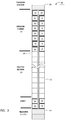
- FIG. 1 depicts an elevator system 10 in an exemplary embodiment.
- Elevator system 10 includes a first hoistway 12 in which elevators cars travel upward.
- Elevator system 10 includes a second hoistway 14 in which elevators cars travel downward.
- a first elevator car 16 and a second elevator car 18 may be physically coupled, through a coupler, so that the first elevator car 16 and second elevator car 18 travel together.
- Elevator system 10 transports elevators cars 16 and 18 from a first floor (e.g., a lobby), through a shuttle section 20 to serviced floors 22.
- a first floor e.g., a lobby
- an upper transfer station 30 imparts horizontal motion to elevator cars 16 and 18 to move elevator cars 16 and 18 from the first hoistway 12 to the second hoistway 14. It is understood that upper transfer station 30 may be located at the top floor, rather than above the top floor.
- Upper transfer station 30 transfers both the first elevator car 16 and the second elevator car 18 at the same time, so that the first elevator car 16 and the second elevator car 18 remain connected during the horizontal transfer between first hoistway 12 and the second hoistway 14.
- lower transfer station 32 to impart horizontal motion to elevator cars 16 and 18 to move elevator cars 16 and 18 from the second hoistway 14 to the first hoistway 12. It is understood that lower transfer station 32 may be located at the first floor, rather than below the first floor. Lower transfer station 32 transfers both the first elevator car 16 and the second elevator car 18 at the same time, so that the first elevator car 16 and the second elevator car 18 remain connected during the horizontal transfer between second hoistway 14 and the first hoistway 12.
- FIG. 2 is a flowchart of a process for operating the elevator system of FIG. 1 in an exemplary embodiment.
- the process begins at 100 where the first car 16 and second 18 are physically coupled. This may be done using known couplers, such as electro-mechanical couplers, electro-magnetic couplers, etc.
- First elevator car 16 and second elevator car 18 may be coupled at the lower transfer station 32, but it is understood that the first elevator car 16 and second elevator car 18 may be coupled at other locations.
- first elevator car 16 and second elevator car 18 are sent to the lobby. Passengers may be notified of the floors that first elevator car 16 and second elevator car 18 serve, respectively, so that passengers board the appropriate elevator car.
- the first elevator car 16 and second elevator car 18 travel upwards through shuttle section 20. Since the first elevator car 16 and second elevator car 18 are coupled together, there is no need to control the spacing between the first elevator car 16 and second elevator car 18. As such, first elevator car 16 and second elevator car 18 can travel at an increased speed, relative to systems employing multiple, uncoupled cars traveling in a shuttle section.
- first elevator car 16 and second elevator car 18 reach the serviced floors 22.
- the first elevator car 16 and second elevator car 18 remain coupled.
- first elevator car 16 services a first subset of serviced floors 22 (e.g., the odd floors) at 106 and second elevator car 18 services a second subset of serviced floors 22 (e.g., the even floors) at 108.
- first elevator car 16 and second elevator car 18 Upon traversing the serviced floors 22, first elevator car 16 and second elevator car 18 enter the upper transfer station 30. At 110, the coupled first elevator car 16 and second elevator car 18 are transferred horizontally from the first hoistway 12 to the second hoistway 14. Once transferred, first elevator car 16 and second elevator car 18 begin travel downwards.
- first elevator car 16 and second elevator car 18 enter the serviced floors 22.
- the first elevator car 16 and second elevator car 18 remain coupled.
- first elevator car 16 services the first subset of serviced floors (e.g., the odd floors) at 112
- second elevator car 18 services the second subset of serviced floors (e.g., the even floors) at 114.
- first elevator car 16 and second elevator car 18 travel downwards through shuttle section 20. Since the first elevator car 16 and second elevator car 18 are coupled together, there is no need to control the spacing between the first elevator car 16 and second elevator car 18. As such, first elevator car 16 and second elevator car 18 can travel at an increased speed, relative to systems employing multiple, uncoupled cars traveling in a shuttle section.
- first elevator car 16 and second elevator car 18 reach the lobby to allow egress of passengers. Typically, no passengers enter first elevator car 16 or second elevator car 18 at the lobby floor of second hoistway 14.
- the coupled first elevator car 16 and second elevator car 18 enter lower transfer station 32 and are transferred horizontally from the second hoistway 14 to the first hoistway 12. Once transferred, first elevator car 16 and second elevator car 18 begin travel upwards, as shown at 102.
- FIG. 3 depicts an elevator system 40 in an exemplary embodiment.
- upper transfer station 30 only accommodates one car at a time, rather than two cars.
- first elevator car 16 and second elevator car 18 are decoupled when traveling in the serviced floors 22.
- FIG. 4 is a flowchart of a process for operating the elevator system of FIG. 3 in an exemplary embodiment.
- the process begins at 130 where the first car 16 and second 18 are physically coupled. This may be done using known couplers, such as electro-mechanical couplers, electro-magnetic couplers, etc.
- First elevator car 16 and second elevator car 18 may be coupled at the lower transfer station 32, but it is understood that the first elevator car 16 and second elevator car 18 may be coupled at other locations.
- first elevator car 16 and second elevator car 18 are sent to the lobby. Passengers may be notified of the floors that first elevator car 16 and second elevator car 18 serve, respectively, so that passengers board the appropriate elevator car.
- the first elevator car 16 and second elevator car 18 travel upwards through shuttle section 20. Since the first elevator car 16 and second elevator car 18 are coupled together, there is no need to control the spacing between the first elevator car 16 and second elevator car 18. As such, first elevator car 16 and second elevator car 18 can travel at an increased speed, relative to systems employing multiple, uncoupled cars traveling in a shuttle section.
- first elevator car 16 and second elevator car 18 reach the serviced floors 22.
- the first elevator car 16 and second elevator car 18 are decoupled.
- the coupler joining first elevator car 16 and second elevator car 18 may be activated or deactivated by a controller.
- an electro-mechanical coupler or electro-magnetic coupler may be controlled by control signals from a controller, as described herein with reference to FIG. 9 .
- first elevator car 16 services a first subset of serviced floors 22 (e.g., the lower floors) at 136
- second elevator car 18 services a second subset of serviced floors 22 (e.g., the upper floors) at 138.
- first elevator car 16 and second elevator car 18 Upon traversing the serviced floors, first elevator car 16 and second elevator car 18 enter the upper transfer station 30. At 140, the second elevator car 18 and first elevator car 16 are sequentially transferred horizontally from the first hoistway 12 to the second hoistway 14. The first elevator car 16 and second elevator car 18 change vertical orientation, e.g., the second elevator car 18 is now vertically below the first elevator car 16. Once transferred, first elevator car 16 and second elevator car 18 begin travel downward in the second hoistway 14.
- first elevator car 16 and second elevator car 18 enter the serviced floors 22.
- the first elevator car 16 and second elevator car 18 remain decoupled.
- second elevator car 18 services the first subset of serviced floors (e.g., the lower floors) at 142 and first elevator car 16 services the second subset of serviced floors (e.g., the upper floors) at 144.
- first elevator car 16 and second elevator car 18 are coupled together. As noted above, the coupler joining first elevator car 16 and second elevator car 18 may be controlled by a controller. At 146, the first elevator car 16 and second elevator car 18 travel downward through shuttle section 20. Since the first elevator car 16 and second elevator car 18 are coupled together, there is no need to control the spacing between the first elevator car 16 and second elevator car 18. As such, first elevator car 16 and second elevator car 18 can travel at an increased speed, relative to systems employing multiple, uncoupled cars traveling in a shuttle section.
- first elevator car 16 and second elevator car 18 reach the lobby to allow egress of passengers. Typically, no passengers enter first elevator car 16 or second elevator car 18 at the lobby floor of second hoistway 14.
- the coupled first elevator car 16 and second elevator car 18 enter lower transfer station 32 and are transferred horizontally from the second hoistway 14 to the first hoistway 12. Once transferred, first elevator car 16 and second elevator car 18 begin travel upwards, as shown at 132.
- FIG. 5 depicts an elevator system 50 in an exemplary embodiment.
- the construction of elevator system 50 is similar to that of FIG. 1 .
- upper transfer station 30 and lower transfer station 32 only accommodate one car at a time, rather than two cars.
- FIG. 6 is a flowchart of a process for operating the elevator system of FIG. 5 in an exemplary embodiment.
- the process begins at 160 where the first car 16 and second car 18 are sent to the lobby. Passengers may be notified of the floors that first elevator car 16 and second elevator car 18 serve, respectively, so that passengers board the appropriate elevator car.
- first car 16 and second car 18 are physically coupled by a coupler. This may be done using known couplers, such as electro-mechanical couplers, electro-magnetic couplers, etc.
- first elevator car 16 and second elevator car 18 travel upward through shuttle section 20. Since the first elevator car 16 and second elevator car 18 are coupled together, there is no need to control the spacing between the first elevator car 16 and second elevator car 18. As such, first elevator car 16 and second elevator car 18 can travel at an increased speed, relative to systems employing multiple, uncoupled cars traveling in a shuttle section.
- first elevator car 16 and second elevator car 18 reach the serviced floors 22.
- First elevator car 16 and second elevator car 18 remain coupled.
- first elevator car 16 services a first subset of serviced floors 22 (e.g., the odd floors) at 166 and second elevator car 18 services a second subset of serviced floors 22 (e.g., the even floors) at 168.
- first elevator car 16 and second elevator car 18 are decoupled.
- the coupler joining first elevator car 16 and second elevator car 18 may be activated or deactivated by a controller.
- an electro-mechanical coupler or electro-magnetic coupler may be controlled by control signals from a controller.
- the second car 18 and first car 16 enter the upper transfer station 30, one at a time.
- the second elevator car 18 and first elevator car 16 are sequentially transferred horizontally from the first hoistway 12 to the second hoistway 14.
- the first elevator car 16 and second elevator car 18 change vertical orientation, e.g., the second elevator car 18 is now vertically below the first elevator car 16.
- first elevator car 16 and second elevator car 18 are coupled.
- the coupler joining first elevator car 16 and second elevator car 18 may be activated or deactivated by a controller.
- an electro-mechanical coupler or electro-magnetic coupler may be controlled by control signals from a controller.
- first elevator car 16 and second elevator car 18 service the serviced floors 22. Due to the change in vertical orientation of first elevator car 16 and second elevator car 18, first elevator car 16 services the second subset of serviced floors (e.g., the even floors) at 172 and second elevator car 18 services the first subset of serviced floors (e.g., the odd floors) at 174.
- first elevator car 16 services the second subset of serviced floors (e.g., the even floors) at 172
- second elevator car 18 services the first subset of serviced floors (e.g., the odd floors) at 174.
- first elevator car 16 and second elevator car 18 travel downward through shuttle section 20. Since the first elevator car 16 and second elevator car 18 are coupled together, there is no need to control the spacing between the first elevator car 16 and second elevator car 18. As such, first elevator car 16 and second elevator car 18 can travel at an increased speed, relative to systems employing multiple, uncoupled cars traveling in a shuttle section.
- first elevator car 16 and second elevator car 18 reach the lobby to allow egress of passengers. Typically, no passengers enter first elevator car 16 or second elevator car 18 at the lobby floor of second hoistway 14.
- first elevator car 16 and second elevator car 18 are decoupled. Once decoupled, the second car 18 and first car 16 enter the lower transfer station 32, one at a time.
- the second elevator car 18 and first elevator car 16 are transferred horizontally from the second hoistway 14 to the first hoistway 12.
- the first elevator car 16 and second elevator car 18 change vertical orientation, e.g., the second elevator car 18 is now vertically above the first elevator car 16. Once transferred, first elevator car 16 and second elevator car 18 are sent to the lobby in first hoistway 12, as shown at 160.
- FIG. 7 depicts an elevator system 60 in an exemplary embodiment.
- the construction of elevator system 60 is similar to that of FIG. 1 .
- upper transfer station 30 and lower transfer station 32 only accommodate one car at a time, rather than two cars.
- FIG. 8 is a flowchart of a process for operating the elevator system of FIG. 7 in an exemplary embodiment.
- the process begins at 190 where the first car 16 and second car 18 are sent to the lobby. Passengers may be notified of the floors that first elevator car 16 and second elevator car 18 serve, respectively, so that passengers board the appropriate elevator car.
- first car 16 and second car 18 are physically coupled by a coupler. This may be done using known couplers, such as electro-mechanical couplers, electro-magnetic couplers, etc.
- first elevator car 16 and second elevator car 18 travel upward through shuttle section 20. Since the first elevator car 16 and second elevator car 18 are coupled together, there is no need to control the spacing between the first elevator car 16 and second elevator car 18. As such, first elevator car 16 and second elevator car 18 can travel at an increased speed, relative to systems employing multiple, uncoupled cars traveling in a shuttle section.
- first elevator car 16 and second elevator car 18 reach the serviced floors 22.
- first elevator car 16 and second elevator car 18 are decoupled.
- the coupler joining first elevator car 16 and second elevator car 18 may be activated or deactivated by a controller.
- an electro-mechanical coupler or electro-magnetic coupler may be controlled by control signals from a controller.
- first elevator car 16 services a first subset of serviced floors 22 (e.g., the lower floors) at 196 and second elevator car 18 services a second subset of serviced floors 22 (e.g., the upper floors) at 198.
- the second car 18 and first car 16 Upon traversing the serviced floors, the second car 18 and first car 16 enter the upper transfer station 30, one at a time. At 200, the second elevator car 18 and first elevator car 16 are sequentially transferred horizontally from the first hoistway 12 to the second hoistway 14. The first elevator car 16 and second elevator car 18 change vertical orientation, e.g., the second elevator car 18 is now vertically below the first elevator car 16.
- first elevator car 16 and second elevator car 18 begin travel downward in the second hoistway 14.
- the first elevator car 16 and second elevator car 18 enter the serviced floors 22.
- the first elevator car 16 and second elevator car 18 remain decoupled. Due to the change in vertical orientation, first elevator car 16 services the second subset of serviced floors (e.g., the upper floors) at 202 and second elevator car 18 services the first subset of serviced floors (e.g., the lower floors) at 204.
- first elevator car 16 and second elevator car 18 are coupled together. As noted above, the coupler joining first elevator car 16 and second elevator car 18 may be controlled by a controller. At 206, the first elevator car 16 and second elevator car 18 travel downward through shuttle section 20. Since the first elevator car 16 and second elevator car 18 are coupled together, there is no need to control the spacing between the first elevator car 16 and second elevator car 18. As such, first elevator car 16 and second elevator car 18 can travel at an increased speed, relative to systems employing multiple, uncoupled cars traveling in a shuttle section.
- first elevator car 16 and second elevator car 18 reach the lobby to allow egress of passengers. Typically, no passengers enter first elevator car 16 or second elevator car 18 at the lobby floor of second hoistway 14.
- first elevator car 16 and second elevator car 18 are decoupled. Once decoupled, the second car 18 and first car 16 enter the lower transfer station 32, one at a time.
- the second elevator car 18 and first elevator car 16 are sequentially transferred horizontally from the second hoistway 14 to the first hoistway 12.
- the first elevator car 16 and second elevator car 18 change vertical orientation, e.g., the second elevator car 18 is now vertically above the first elevator car 16. Once transferred, first elevator car 16 and second elevator car 18 are sent to the lobby, as shown at 190.
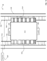
- FIG. 9 depicts an elevator system 70 having a self-propelled elevator car 312.
- Elevator system 70 includes an elevator car 312 that travels in a hoistway 314. Elevator car 312 travels along one or more guide rails 316 extending along the length of hoistway 314.
- Elevator system 70 employs a linear motor having primary windings 318, which may be provided along guide rails 316 or located separate from guide rails 316.
- Primary windings 318 may be provided on one or both sides of elevator car 312.
- the primary windings 318 serve as stator windings of a permanent magnet synchronous motor to impart motion to elevator car 312.
- Primary windings 318 may be arranged in three phases, as is known in the linear motor art.
- Permanent magnets 319 may be mounted to car 312 to serve as the secondary moving portion of the permanent magnet synchronous motor.
- coupler 330 which may be placed at the top and/or the bottom of elevator car 312.
- coupler 330 may be implemented using an electro-mechanical or electro-magnetic coupling, that can be engaged or disengaged with a mating coupler in response to control signals from controller 320. If cars do not change relative vertical orientation ( FIGs. 1 and 3 ), then a single coupler 330 may be used on each elevator car. If cars do change relative vertical orientation ( FIGs. 5 and 7 ), then two couplers 330 may be used, one on the top and one on the bottom of each elevator car.
- Controller 320 provides drive signals to the primary windings 318 to impart motion to the elevator car 312.
- Controller 320 may be implemented using a general-purpose microprocessor executing a computer program stored on a storage medium to perform the operations described herein.
- controller 320 may be implemented in hardware (e.g., ASIC, FPGA) or in a combination of hardware/software.
- Controller 320 may also be part of an elevator control system.
- Controller 320 may include power circuitry (e.g., an inverter or drive) to power the primary windings 318.
- first elevator car 16 and second elevator car 18 are roped, that is, conveyed by tension members coupled to the elevator cars and one or more counterweights.
- a drive unit imparts force to the tension member to transition elevator cars up or down.
- Embodiments described herein refer to coupling a first elevator car and a second elevator car. It is understood that more than two elevator cars may be coupled, and embodiments are not limited to coupling two elevator cars.
- Embodiments provide a number of benefits. By using multiple cars in a single hoistway, the footprint of the elevator system is reduced, which results in increased utilization of building space for customer. By coupling cars during travel in the shuttle sections, simplified traffic management is used, as cars cannot collide in the shuttle section. This also results in a shorter travel time through the shuttle section, as higher speeds are attainable.
Claims (11)
- Système élévateur (10; 40; 50; 60; 70), comprenant :une première cage (12) ayant une section navette (20) et des niveaux desservis (22) ;une deuxième cage (14) ayant une section navette (20) et des niveaux desservis (22) ;une première cabine d'ascenseur (16) ;une deuxième cabine d'ascenseur (18) ;un coupleur (330) connectant physiquement la première cabine d'ascenseur (16) et la deuxième cabine d'ascenseur (18) pendant le déplacement dans la section navette (20) ;une station de transfert supérieure (30) pour transférer au moins une cabine parmi la première cabine d'ascenseur (16) et la deuxième cabine d'ascenseur (18) de la première cage (12) vers la deuxième cage (14) ;une station de transfert inférieure (32) pour transférer au moins une cabine parmi la première cabine d'ascenseur (16) et la deuxième cabine d'ascenseur (18) de la deuxième cage (14) vers la première cage (12) ;caractérisé en ce que la première cabine d'ascenseur (16) et la deuxième cabine d'ascenseur (18) sont découplées pour desservir les niveaux desservis (22).
- Système élévateur (10) selon la revendication 1, dans lequel :la station de transfert supérieure (30) transfère la première cabine d'ascenseur (16) et la deuxième cabine d'ascenseur (18) de la première cage (12) vers la deuxième cage (14) en même temps.
- Système élévateur selon la revendication 2, dans lequel :la première cabine d'ascenseur (16) et la deuxième cabine d'ascenseur (18) sont couplées pendant le transfert de la première cage (12) vers la deuxième cage (14).
- Système élévateur (10) selon l'une quelconque des revendications 1 à 3, dans lequel :la station de transfert inférieure (32) transfère la première cabine d'ascenseur (16) et la deuxième cabine d'ascenseur (18) de la deuxième cage (14) vers la première cage (12) en même temps.
- Système élévateur (10) selon la revendication 4, dans lequel :la première cabine d'ascenseur (16) et la deuxième cabine d'ascenseur (18) sont couplées pendant le transfert de la deuxième cage (14) vers la première cage (12).
- Système élévateur (10) selon l'une quelconque des revendications 1 à 5, dans lequel :pendant le déplacement dans la première cage (12), la première cabine d'ascenseur (16) dessert un premier sous-ensemble des niveaux desservis et la deuxième cabine d'ascenseur (18) dessert un deuxième sous-ensemble des niveaux desservis (22).
- Système élévateur (10) selon la revendication 6, dans lequel :pendant le déplacement dans la deuxième cage (14), la première cabine d'ascenseur (16) dessert le premier sous-ensemble des niveaux desservis et la deuxième cabine d'ascenseur (18) dessert le deuxième sous-ensemble des niveaux desservis (22).
- Système élévateur (40; 50; 60; 70) selon l'une quelconque des revendications 1 à 7, dans lequel :la station de transfert supérieure (30) transfère la première cabine d'ascenseur (16) et la deuxième cabine d'ascenseur (18) de la première cage (12) vers la deuxième cage (14) une à la fois.
- Système élévateur (50) selon l'une quelconque des revendications 1 à 8, dans lequel :pendant le déplacement dans la première cage (12), la première cabine d'ascenseur (16) dessert un premier sous-ensemble des niveaux desservis (22) et la deuxième cabine d'ascenseur (18) dessert un deuxième sous-ensemble des niveaux desservis (22), pendant le déplacement dans la deuxième cage (14), la première cabine d'ascenseur (16) dessert le deuxième sous-ensemble des niveaux desservis (22) et la deuxième cabine d'ascenseur (18) dessert le premier sous-ensemble des niveaux desservis.
- Procédé de fonctionnement d'un système élévateur (10; 40; 50; 60; 70), le procédé comprenant les étapes consistant à :coupler physiquement (100; 130; 162; 192) une première cabine d'ascenseur (16) et une deuxième cabine d'ascenseur (18) ;diriger (104; 134; 164; 194) la première cabine d'ascenseur (16) et la deuxième cabine d'ascenseur (18) vers le haut dans une section navette (20) d'une première cage (12) ;transférer (110; 134; 164; 194) la première cabine d'ascenseur (16) et la deuxième cabine d'ascenseur (18) de la première cage (12) vers une deuxième cage (14) ; etdiriger la première cabine d'ascenseur (16) et une deuxième cabine d'ascenseur (18) vers le bas dans la deuxième cage (14), la première cabine d'ascenseur (16) et la deuxième cabine d'ascenseur (18) étant couplées avant de se déplacer vers le bas dans une section navette (20) de la deuxième cage (14),diriger la première cabine d'ascenseur (16) et la deuxième cabine d'ascenseur (18) vers le haut à travers les niveaux desservis (22) de la première cage (12), et diriger la première cabine d'ascenseur (16) et la deuxième cabine d'ascenseur (18) vers le bas à travers des niveaux desservis (22) de la deuxième cage (14),caractérisé en ce que la première cabine d'ascenseur (16) et la deuxième cabine d'ascenseur (18) sont découplées pendant le déplacement à travers les niveaux desservis (22) de la première cage (12) eten ce que la première cabine d'ascenseur (16) et la deuxième cabine d'ascenseur (18) sont découplées pendant le déplacement à travers les niveaux desservis (22) de la deuxième cage (14).
- Procédé selon la revendication 10, dans lequel :le transfert de la première cabine d'ascenseur (16) et de la deuxième cabine d'ascenseur (18) de la première cage (12) vers une deuxième cage (14) comprend le transfert à la fois de la première cabine d'ascenseur (16) et de la deuxième cabine d'ascenseur (18) en même temps, oule transfert de la première cabine d'ascenseur (16) et de la deuxième cabine d'ascenseur (18) de la première cage (12) vers une deuxième cage (14) comprend le transfert de la première cabine d'ascenseur (16) et de la deuxième cabine d'ascenseur (18) une à la fois.
Applications Claiming Priority (1)
| Application Number | Priority Date | Filing Date | Title |
|---|---|---|---|
| PCT/US2013/039862 WO2014182284A1 (fr) | 2013-05-07 | 2013-05-07 | Connexion des cabines dans un système élévateur comprenant plusieurs cabines d'ascenseur |
Publications (3)
| Publication Number | Publication Date |
|---|---|
| EP2994406A1 EP2994406A1 (fr) | 2016-03-16 |
| EP2994406A4 EP2994406A4 (fr) | 2016-12-21 |
| EP2994406B1 true EP2994406B1 (fr) | 2018-01-10 |
Family
ID=51867600
Family Applications (1)
| Application Number | Title | Priority Date | Filing Date |
|---|---|---|---|
| EP13884081.4A Not-in-force EP2994406B1 (fr) | 2013-05-07 | 2013-05-07 | Connexion des cabines dans un système élévateur comprenant plusieurs cabines d'ascenseur |
Country Status (5)
| Country | Link |
|---|---|
| US (1) | US10059566B2 (fr) |
| EP (1) | EP2994406B1 (fr) |
| CN (1) | CN105189324B (fr) |
| HK (1) | HK1218907A1 (fr) |
| WO (1) | WO2014182284A1 (fr) |
Cited By (1)
| Publication number | Priority date | Publication date | Assignee | Title |
|---|---|---|---|---|
| WO2021219715A2 (fr) | 2020-04-30 | 2021-11-04 | Tk Elevator Innovation And Operations Gmbh | Système d'ascenseur ayant de multiples cabines d'ascenseur |
Families Citing this family (10)
| Publication number | Priority date | Publication date | Assignee | Title |
|---|---|---|---|---|
| EP2978703A4 (fr) * | 2013-03-25 | 2016-11-02 | Otis Elevator Co | Système d'ascenseurs autopropulsés multi-cabines |
| US10829342B2 (en) | 2015-02-05 | 2020-11-10 | Otis Elevator Company | Operational modes for multicar hoistway systems |
| CN107207184B (zh) | 2015-02-05 | 2021-02-09 | 奥的斯电梯公司 | 用于多轿厢井道系统的组外操作 |
| US10370222B2 (en) * | 2015-07-16 | 2019-08-06 | Otis Elevator Company | Ropeless elevator system and a transfer system for a ropeless elevator system |
| EP3397580A4 (fr) * | 2015-12-31 | 2020-01-29 | KONE Corporation | Système d'ascenseur et procédé de fonctionnement de cabines d'ascenseur dans un système d'ascenseur multi-cabines |
| US10399815B2 (en) * | 2016-06-07 | 2019-09-03 | Otis Elevator Company | Car separation control in multi-car elevator system |
| DE102017100884B4 (de) * | 2017-01-18 | 2019-01-24 | Aeris Gmbh | Arbeitsplatzanalysesystem |
| JP7012615B2 (ja) * | 2018-07-31 | 2022-01-28 | 株式会社日立製作所 | マルチカーエレベーター及び乗りかご移動制御方法 |
| DE102018123979A1 (de) * | 2018-09-27 | 2020-04-02 | Thyssenkrupp Ag | Aufzugsystem |
| US11542123B2 (en) * | 2020-08-01 | 2023-01-03 | Otis Elevator Company | Elevator system including a motorized module |
Family Cites Families (41)
| Publication number | Priority date | Publication date | Assignee | Title |
|---|---|---|---|---|
| US1837643A (en) * | 1931-03-28 | 1931-12-22 | Otis Elevator Co | Elevator system |
| US3658155A (en) * | 1970-09-15 | 1972-04-25 | William G Salter | Elevator system |
| JP2507275B2 (ja) * | 1990-10-17 | 1996-06-12 | フジテック株式会社 | 循環式エレベ―タの横行移動装置 |
| JP2736176B2 (ja) | 1991-02-14 | 1998-04-02 | 株式会社東芝 | リニアモータ駆動エレベータの制御装置 |
| JP2875112B2 (ja) | 1992-09-07 | 1999-03-24 | 株式会社東芝 | 自走式エレベータ |
| JP2994891B2 (ja) | 1992-11-27 | 1999-12-27 | 株式会社竹中工務店 | 多層エレベータ装置 |
| JP3345565B2 (ja) * | 1997-04-11 | 2002-11-18 | 森ビル株式会社 | 可変式ダブルデッキエレベーター |
| US5861587A (en) | 1997-11-26 | 1999-01-19 | Otis Elevator Company | Method for operating a double deck elevator car |
| JP3469780B2 (ja) | 1998-05-22 | 2003-11-25 | 富士変速機株式会社 | 循環式エレベータ |
| JP2000086121A (ja) | 1998-09-09 | 2000-03-28 | Ohbayashi Corp | エレベータ装置 |
| EP1357075B1 (fr) * | 2000-11-08 | 2010-03-10 | Mitsubishi Denki Kabushiki Kaisha | Dispositif de cabine pour ascenseurs a double cabine |
| US20030000778A1 (en) * | 2001-06-14 | 2003-01-02 | Rory Smith | Drive system for multiple elevator cars in a single shaft |
| SG102714A1 (en) * | 2002-05-27 | 2004-03-26 | Inventio Ag | Elevator installation with several self-propelled cars and at least three elevator hoistways situated adjacently |
| US7198136B2 (en) * | 2003-09-11 | 2007-04-03 | Otis Elevator Company | Elevator device for a multi-sky-lobby system |
| SG111198A1 (en) * | 2003-10-09 | 2005-05-30 | Inventio Ag | Lift installation for zonal operation in a building, method for zonal operation of such a lift installation and method for modernisation of a lift installation |
| ES2386723T3 (es) * | 2004-12-29 | 2012-08-28 | Otis Elevator Company | Compensación en un sistema de ascensor que tiene múltiples cabinas de ascensor dentro de un único hueco de ascensor |
| US20060163008A1 (en) * | 2005-01-24 | 2006-07-27 | Michael Godwin | Autonomous linear retarder/motor for safe operation of direct drive gearless, rope-less elevators |
| US7841450B2 (en) * | 2005-08-19 | 2010-11-30 | Thyssenkrupp Elevator Capital Corporation | Twin elevator systems |
| ES2349062T3 (es) * | 2007-01-24 | 2010-12-22 | Inventio Ag | Bastidor para un ascensor. |
| WO2008136692A2 (fr) | 2007-05-02 | 2008-11-13 | Maglevvision Corporation | Ascenseur magnétique cyclique à plusieurs cabines avec moteur/générateur électrique linéaire à gravité |
| EP2070860A1 (fr) * | 2007-12-11 | 2009-06-17 | Inventio Ag | Système d'ascenseur doté de cabines d'ascenseur mobiles verticalement et horizontalement |
| EP2221269A1 (fr) * | 2009-02-20 | 2010-08-25 | Inventio AG | Installation d'ascenseur dotée d'un véhicule à plusieurs toits |
| JP2012525309A (ja) * | 2009-04-29 | 2012-10-22 | オーチス エレベータ カンパニー | 単一の昇降路内に複数のかごを含むエレベータシステム |
| CN102741145B (zh) * | 2009-12-15 | 2015-01-07 | 因温特奥股份公司 | 双层升降机设施 |
| EP2444352A1 (fr) * | 2010-10-25 | 2012-04-25 | Inventio AG | Installation d'ascenseur |
| US8925689B2 (en) * | 2011-01-19 | 2015-01-06 | Smart Lifts, Llc | System having a plurality of elevator cabs and counterweights that move independently in different sections of a hoistway |
| CN103502133A (zh) | 2011-05-11 | 2014-01-08 | 奥的斯电梯公司 | 循环输送系统 |
| FI124330B (fi) * | 2012-01-02 | 2014-06-30 | Kone Corp | Hissijärjestely ja menetelmä hissijärjestelyn uudelleenasettelemiseksi |
| KR101760115B1 (ko) * | 2012-04-26 | 2017-07-20 | 아티큘레이티드 퍼니큘레이터 에이비 | 연결식 승강기 |
| EP2953880A4 (fr) * | 2013-02-06 | 2016-10-05 | Otis Elevator Co | Levage de charge autopropulsée pour systèmes d'ascenseur |
| EP2978703A4 (fr) * | 2013-03-25 | 2016-11-02 | Otis Elevator Co | Système d'ascenseurs autopropulsés multi-cabines |
| US10196233B2 (en) * | 2013-12-05 | 2019-02-05 | Otis Elevator Company | Elevator system assigning cars to floor groups |
| WO2015084371A1 (fr) * | 2013-12-05 | 2015-06-11 | Otis Elevator Company | Approche d'installation d'ascenseur de grande hauteur sans câble |
| WO2015084364A1 (fr) * | 2013-12-05 | 2015-06-11 | Otis Elevator Company | Système d'ascenseur sans câble |
| US20160297648A1 (en) * | 2013-12-05 | 2016-10-13 | Otis Elevator Company | Stator reduction in ropeless elevator transfer station |
| WO2015084367A1 (fr) * | 2013-12-05 | 2015-06-11 | Otis Elevator Company | Ascenseur sans câble à haute vitesse comprenant un nombre différent de cages d'ascenseur pour un déplacement vers le haut et pour un déplacement vers le bas dans un groupe |
| US20170088396A1 (en) * | 2014-03-14 | 2017-03-30 | Otis Elevator Company | Robust startup method for ropeless elevator |
| DE102014220966A1 (de) * | 2014-10-16 | 2016-04-21 | Thyssenkrupp Elevator Ag | Verfahren zum Betreiben einer Transportanlage sowie entsprechende Transportanlage |
| US9758347B2 (en) * | 2014-12-02 | 2017-09-12 | ThyssenKrupp Elevator AG; ThyssenKrupp AG | Arrangement and method to move at least two elevator cars independently in at least one hoistway |
| CN106395568B (zh) * | 2015-07-31 | 2020-05-05 | 奥的斯电梯公司 | 电梯恢复轿厢 |
| US10486940B2 (en) * | 2015-08-25 | 2019-11-26 | Otis Elevator Company | Alignment system for an elevator car |
-
2013
- 2013-05-07 US US14/888,745 patent/US10059566B2/en active Active
- 2013-05-07 CN CN201380076394.2A patent/CN105189324B/zh active Active
- 2013-05-07 EP EP13884081.4A patent/EP2994406B1/fr not_active Not-in-force
- 2013-05-07 WO PCT/US2013/039862 patent/WO2014182284A1/fr active Application Filing
-
2016
- 2016-06-17 HK HK16106973.0A patent/HK1218907A1/zh unknown
Non-Patent Citations (1)
| Title |
|---|
| None * |
Cited By (2)
| Publication number | Priority date | Publication date | Assignee | Title |
|---|---|---|---|---|
| WO2021219715A2 (fr) | 2020-04-30 | 2021-11-04 | Tk Elevator Innovation And Operations Gmbh | Système d'ascenseur ayant de multiples cabines d'ascenseur |
| DE102020205506A1 (de) | 2020-04-30 | 2021-11-04 | Thyssenkrupp Elevator Innovation And Operations Ag | Aufzugssystem mit mehreren Aufzugskabinen |
Also Published As
| Publication number | Publication date |
|---|---|
| US20160075534A1 (en) | 2016-03-17 |
| US10059566B2 (en) | 2018-08-28 |
| EP2994406A1 (fr) | 2016-03-16 |
| CN105189324A (zh) | 2015-12-23 |
| CN105189324B (zh) | 2017-12-05 |
| WO2014182284A1 (fr) | 2014-11-13 |
| HK1218907A1 (zh) | 2017-03-17 |
| EP2994406A4 (fr) | 2016-12-21 |
Similar Documents
| Publication | Publication Date | Title |
|---|---|---|
| EP2994406B1 (fr) | Connexion des cabines dans un système élévateur comprenant plusieurs cabines d'ascenseur | |
| US10118799B2 (en) | Multicar self-propelled elevator system | |
| US9758347B2 (en) | Arrangement and method to move at least two elevator cars independently in at least one hoistway | |
| JP6710226B2 (ja) | リニアモータ式エレベータ | |
| TWI293941B (en) | Elevator installation with several self-propelled cars and at least three elevator hoistways situated adjacently | |
| CN107207208B (zh) | 用于电梯系统安装的交通工具和方法 | |
| US10865072B2 (en) | Intermediate transfer station | |
| US20180022575A1 (en) | Wireless communication for self-propelled elevator system | |
| EP3118149B1 (fr) | Système de commande pour système d'ascenseur multicar | |
| CN106542392B (zh) | 电梯制动控制系统 | |
| CN107108165B (zh) | 用于无绳电梯系统的传送站和轿厢分离机构 | |
| US20180029829A1 (en) | Mechanically integrated propulsion guiding unit | |
| JP2016528123A5 (fr) | ||
| CN105324323A (zh) | 具有与轿厢速度成比例的绕组的自推进电梯系统 | |
| EP3401267A1 (fr) | Installation modulaire d'un système d'ascenseur sans câble | |
| US20200172379A1 (en) | Linear motor arrangement comprising two drive trains | |
| CN107445013B (zh) | 用于电梯系统的制动系统 | |
| US20170355562A1 (en) | Fire service sequence for multicar elevator systems | |
| JP2004018178A (ja) | エレベーター装置 | |
| JP6610501B2 (ja) | ロープレスエレベーター装置 | |
| JP3424451B2 (ja) | ロープレス式エレベータ | |
| JPH04365759A (ja) | 自走式エレベータの電源供給方法 | |
| JPH07106850B2 (ja) | エレベータ装置 |
Legal Events
| Date | Code | Title | Description |
|---|---|---|---|
| PUAI | Public reference made under article 153(3) epc to a published international application that has entered the european phase |
Free format text: ORIGINAL CODE: 0009012 |
|
| 17P | Request for examination filed |
Effective date: 20151203 |
|
| AK | Designated contracting states |
Kind code of ref document: A1 Designated state(s): AL AT BE BG CH CY CZ DE DK EE ES FI FR GB GR HR HU IE IS IT LI LT LU LV MC MK MT NL NO PL PT RO RS SE SI SK SM TR |
|
| AX | Request for extension of the european patent |
Extension state: BA ME |
|
| DAX | Request for extension of the european patent (deleted) | ||
| A4 | Supplementary search report drawn up and despatched |
Effective date: 20161118 |
|
| RIC1 | Information provided on ipc code assigned before grant |
Ipc: B66B 1/36 20060101AFI20161114BHEP Ipc: B66B 9/02 20060101ALI20161114BHEP Ipc: B66B 1/24 20060101ALI20161114BHEP Ipc: B66B 9/00 20060101ALI20161114BHEP |
|
| GRAP | Despatch of communication of intention to grant a patent |
Free format text: ORIGINAL CODE: EPIDOSNIGR1 |
|
| RIC1 | Information provided on ipc code assigned before grant |
Ipc: B66B 9/02 20060101ALI20170628BHEP Ipc: B66B 1/36 20060101AFI20170628BHEP Ipc: B66B 9/00 20060101ALI20170628BHEP Ipc: B66B 1/24 20060101ALI20170628BHEP |
|
| INTG | Intention to grant announced |
Effective date: 20170802 |
|
| RAP1 | Party data changed (applicant data changed or rights of an application transferred) |
Owner name: OTIS ELEVATOR COMPANY |
|
| GRAS | Grant fee paid |
Free format text: ORIGINAL CODE: EPIDOSNIGR3 |
|
| GRAA | (expected) grant |
Free format text: ORIGINAL CODE: 0009210 |
|
| AK | Designated contracting states |
Kind code of ref document: B1 Designated state(s): AL AT BE BG CH CY CZ DE DK EE ES FI FR GB GR HR HU IE IS IT LI LT LU LV MC MK MT NL NO PL PT RO RS SE SI SK SM TR |
|
| REG | Reference to a national code |
Ref country code: CH Ref legal event code: EP Ref country code: AT Ref legal event code: REF Ref document number: 962154 Country of ref document: AT Kind code of ref document: T Effective date: 20180115 |
|
| REG | Reference to a national code |
Ref country code: IE Ref legal event code: FG4D |
|
| REG | Reference to a national code |
Ref country code: DE Ref legal event code: R096 Ref document number: 602013032238 Country of ref document: DE |
|
| REG | Reference to a national code |
Ref country code: NL Ref legal event code: MP Effective date: 20180110 |
|
| REG | Reference to a national code |
Ref country code: AT Ref legal event code: MK05 Ref document number: 962154 Country of ref document: AT Kind code of ref document: T Effective date: 20180110 |
|
| PG25 | Lapsed in a contracting state [announced via postgrant information from national office to epo] |
Ref country code: NL Free format text: LAPSE BECAUSE OF FAILURE TO SUBMIT A TRANSLATION OF THE DESCRIPTION OR TO PAY THE FEE WITHIN THE PRESCRIBED TIME-LIMIT Effective date: 20180110 |
|
| PG25 | Lapsed in a contracting state [announced via postgrant information from national office to epo] |
Ref country code: ES Free format text: LAPSE BECAUSE OF FAILURE TO SUBMIT A TRANSLATION OF THE DESCRIPTION OR TO PAY THE FEE WITHIN THE PRESCRIBED TIME-LIMIT Effective date: 20180110 Ref country code: HR Free format text: LAPSE BECAUSE OF FAILURE TO SUBMIT A TRANSLATION OF THE DESCRIPTION OR TO PAY THE FEE WITHIN THE PRESCRIBED TIME-LIMIT Effective date: 20180110 Ref country code: CY Free format text: LAPSE BECAUSE OF FAILURE TO SUBMIT A TRANSLATION OF THE DESCRIPTION OR TO PAY THE FEE WITHIN THE PRESCRIBED TIME-LIMIT Effective date: 20180110 Ref country code: LT Free format text: LAPSE BECAUSE OF FAILURE TO SUBMIT A TRANSLATION OF THE DESCRIPTION OR TO PAY THE FEE WITHIN THE PRESCRIBED TIME-LIMIT Effective date: 20180110 Ref country code: NO Free format text: LAPSE BECAUSE OF FAILURE TO SUBMIT A TRANSLATION OF THE DESCRIPTION OR TO PAY THE FEE WITHIN THE PRESCRIBED TIME-LIMIT Effective date: 20180410 Ref country code: FI Free format text: LAPSE BECAUSE OF FAILURE TO SUBMIT A TRANSLATION OF THE DESCRIPTION OR TO PAY THE FEE WITHIN THE PRESCRIBED TIME-LIMIT Effective date: 20180110 |
|
| PG25 | Lapsed in a contracting state [announced via postgrant information from national office to epo] |
Ref country code: IS Free format text: LAPSE BECAUSE OF FAILURE TO SUBMIT A TRANSLATION OF THE DESCRIPTION OR TO PAY THE FEE WITHIN THE PRESCRIBED TIME-LIMIT Effective date: 20180510 Ref country code: GR Free format text: LAPSE BECAUSE OF FAILURE TO SUBMIT A TRANSLATION OF THE DESCRIPTION OR TO PAY THE FEE WITHIN THE PRESCRIBED TIME-LIMIT Effective date: 20180411 Ref country code: PL Free format text: LAPSE BECAUSE OF FAILURE TO SUBMIT A TRANSLATION OF THE DESCRIPTION OR TO PAY THE FEE WITHIN THE PRESCRIBED TIME-LIMIT Effective date: 20180110 Ref country code: AT Free format text: LAPSE BECAUSE OF FAILURE TO SUBMIT A TRANSLATION OF THE DESCRIPTION OR TO PAY THE FEE WITHIN THE PRESCRIBED TIME-LIMIT Effective date: 20180110 Ref country code: SE Free format text: LAPSE BECAUSE OF FAILURE TO SUBMIT A TRANSLATION OF THE DESCRIPTION OR TO PAY THE FEE WITHIN THE PRESCRIBED TIME-LIMIT Effective date: 20180110 Ref country code: LV Free format text: LAPSE BECAUSE OF FAILURE TO SUBMIT A TRANSLATION OF THE DESCRIPTION OR TO PAY THE FEE WITHIN THE PRESCRIBED TIME-LIMIT Effective date: 20180110 Ref country code: BG Free format text: LAPSE BECAUSE OF FAILURE TO SUBMIT A TRANSLATION OF THE DESCRIPTION OR TO PAY THE FEE WITHIN THE PRESCRIBED TIME-LIMIT Effective date: 20180410 Ref country code: RS Free format text: LAPSE BECAUSE OF FAILURE TO SUBMIT A TRANSLATION OF THE DESCRIPTION OR TO PAY THE FEE WITHIN THE PRESCRIBED TIME-LIMIT Effective date: 20180110 |
|
| REG | Reference to a national code |
Ref country code: DE Ref legal event code: R097 Ref document number: 602013032238 Country of ref document: DE |
|
| PG25 | Lapsed in a contracting state [announced via postgrant information from national office to epo] |
Ref country code: EE Free format text: LAPSE BECAUSE OF FAILURE TO SUBMIT A TRANSLATION OF THE DESCRIPTION OR TO PAY THE FEE WITHIN THE PRESCRIBED TIME-LIMIT Effective date: 20180110 Ref country code: IT Free format text: LAPSE BECAUSE OF FAILURE TO SUBMIT A TRANSLATION OF THE DESCRIPTION OR TO PAY THE FEE WITHIN THE PRESCRIBED TIME-LIMIT Effective date: 20180110 Ref country code: AL Free format text: LAPSE BECAUSE OF FAILURE TO SUBMIT A TRANSLATION OF THE DESCRIPTION OR TO PAY THE FEE WITHIN THE PRESCRIBED TIME-LIMIT Effective date: 20180110 Ref country code: RO Free format text: LAPSE BECAUSE OF FAILURE TO SUBMIT A TRANSLATION OF THE DESCRIPTION OR TO PAY THE FEE WITHIN THE PRESCRIBED TIME-LIMIT Effective date: 20180110 |
|
| PGFP | Annual fee paid to national office [announced via postgrant information from national office to epo] |
Ref country code: GB Payment date: 20180419 Year of fee payment: 6 |
|
| PLBE | No opposition filed within time limit |
Free format text: ORIGINAL CODE: 0009261 |
|
| STAA | Information on the status of an ep patent application or granted ep patent |
Free format text: STATUS: NO OPPOSITION FILED WITHIN TIME LIMIT |
|
| PG25 | Lapsed in a contracting state [announced via postgrant information from national office to epo] |
Ref country code: CZ Free format text: LAPSE BECAUSE OF FAILURE TO SUBMIT A TRANSLATION OF THE DESCRIPTION OR TO PAY THE FEE WITHIN THE PRESCRIBED TIME-LIMIT Effective date: 20180110 Ref country code: SM Free format text: LAPSE BECAUSE OF FAILURE TO SUBMIT A TRANSLATION OF THE DESCRIPTION OR TO PAY THE FEE WITHIN THE PRESCRIBED TIME-LIMIT Effective date: 20180110 Ref country code: DK Free format text: LAPSE BECAUSE OF FAILURE TO SUBMIT A TRANSLATION OF THE DESCRIPTION OR TO PAY THE FEE WITHIN THE PRESCRIBED TIME-LIMIT Effective date: 20180110 Ref country code: SK Free format text: LAPSE BECAUSE OF FAILURE TO SUBMIT A TRANSLATION OF THE DESCRIPTION OR TO PAY THE FEE WITHIN THE PRESCRIBED TIME-LIMIT Effective date: 20180110 |
|
| REG | Reference to a national code |
Ref country code: DE Ref legal event code: R119 Ref document number: 602013032238 Country of ref document: DE |
|
| REG | Reference to a national code |
Ref country code: CH Ref legal event code: PL |
|
| 26N | No opposition filed |
Effective date: 20181011 |
|
| REG | Reference to a national code |
Ref country code: BE Ref legal event code: MM Effective date: 20180531 |
|
| PG25 | Lapsed in a contracting state [announced via postgrant information from national office to epo] |
Ref country code: MC Free format text: LAPSE BECAUSE OF FAILURE TO SUBMIT A TRANSLATION OF THE DESCRIPTION OR TO PAY THE FEE WITHIN THE PRESCRIBED TIME-LIMIT Effective date: 20180110 |
|
| REG | Reference to a national code |
Ref country code: IE Ref legal event code: MM4A |
|
| PG25 | Lapsed in a contracting state [announced via postgrant information from national office to epo] |
Ref country code: CH Free format text: LAPSE BECAUSE OF NON-PAYMENT OF DUE FEES Effective date: 20180531 Ref country code: LI Free format text: LAPSE BECAUSE OF NON-PAYMENT OF DUE FEES Effective date: 20180531 Ref country code: SI Free format text: LAPSE BECAUSE OF FAILURE TO SUBMIT A TRANSLATION OF THE DESCRIPTION OR TO PAY THE FEE WITHIN THE PRESCRIBED TIME-LIMIT Effective date: 20180110 |
|
| PG25 | Lapsed in a contracting state [announced via postgrant information from national office to epo] |
Ref country code: LU Free format text: LAPSE BECAUSE OF NON-PAYMENT OF DUE FEES Effective date: 20180507 |
|
| PG25 | Lapsed in a contracting state [announced via postgrant information from national office to epo] |
Ref country code: FR Free format text: LAPSE BECAUSE OF NON-PAYMENT OF DUE FEES Effective date: 20180531 Ref country code: DE Free format text: LAPSE BECAUSE OF NON-PAYMENT OF DUE FEES Effective date: 20181201 Ref country code: IE Free format text: LAPSE BECAUSE OF NON-PAYMENT OF DUE FEES Effective date: 20180507 |
|
| PG25 | Lapsed in a contracting state [announced via postgrant information from national office to epo] |
Ref country code: BE Free format text: LAPSE BECAUSE OF NON-PAYMENT OF DUE FEES Effective date: 20180531 |
|
| GBPC | Gb: european patent ceased through non-payment of renewal fee |
Effective date: 20190507 |
|
| PG25 | Lapsed in a contracting state [announced via postgrant information from national office to epo] |
Ref country code: MT Free format text: LAPSE BECAUSE OF NON-PAYMENT OF DUE FEES Effective date: 20180507 |
|
| PG25 | Lapsed in a contracting state [announced via postgrant information from national office to epo] |
Ref country code: TR Free format text: LAPSE BECAUSE OF FAILURE TO SUBMIT A TRANSLATION OF THE DESCRIPTION OR TO PAY THE FEE WITHIN THE PRESCRIBED TIME-LIMIT Effective date: 20180110 |
|
| PG25 | Lapsed in a contracting state [announced via postgrant information from national office to epo] |
Ref country code: GB Free format text: LAPSE BECAUSE OF NON-PAYMENT OF DUE FEES Effective date: 20190507 |
|
| PG25 | Lapsed in a contracting state [announced via postgrant information from national office to epo] |
Ref country code: PT Free format text: LAPSE BECAUSE OF FAILURE TO SUBMIT A TRANSLATION OF THE DESCRIPTION OR TO PAY THE FEE WITHIN THE PRESCRIBED TIME-LIMIT Effective date: 20180110 |
|
| PG25 | Lapsed in a contracting state [announced via postgrant information from national office to epo] |
Ref country code: MK Free format text: LAPSE BECAUSE OF NON-PAYMENT OF DUE FEES Effective date: 20180110 Ref country code: HU Free format text: LAPSE BECAUSE OF FAILURE TO SUBMIT A TRANSLATION OF THE DESCRIPTION OR TO PAY THE FEE WITHIN THE PRESCRIBED TIME-LIMIT; INVALID AB INITIO Effective date: 20130507 |