EP2990791B1 - Switching valve for a flow-type analysis device - Google Patents
Switching valve for a flow-type analysis device Download PDFInfo
- Publication number
- EP2990791B1 EP2990791B1 EP14788272.4A EP14788272A EP2990791B1 EP 2990791 B1 EP2990791 B1 EP 2990791B1 EP 14788272 A EP14788272 A EP 14788272A EP 2990791 B1 EP2990791 B1 EP 2990791B1
- Authority
- EP
- European Patent Office
- Prior art keywords
- flow path
- pipe connection
- valve
- connection port
- arc
- Prior art date
- Legal status (The legal status is an assumption and is not a legal conclusion. Google has not performed a legal analysis and makes no representation as to the accuracy of the status listed.)
- Active
Links
- 238000004458 analytical method Methods 0.000 title claims description 57
- 239000007788 liquid Substances 0.000 claims description 223
- 238000004891 communication Methods 0.000 claims description 60
- 230000000740 bleeding effect Effects 0.000 claims description 39
- 102000001554 Hemoglobins Human genes 0.000 claims description 15
- 108010054147 Hemoglobins Proteins 0.000 claims description 15
- 230000033001 locomotion Effects 0.000 claims description 15
- 238000000034 method Methods 0.000 claims description 15
- 239000008280 blood Substances 0.000 claims description 12
- 210000004369 blood Anatomy 0.000 claims description 12
- 238000004128 high performance liquid chromatography Methods 0.000 claims description 8
- 238000000691 measurement method Methods 0.000 claims description 4
- 239000000523 sample Substances 0.000 description 105
- 238000005406 washing Methods 0.000 description 65
- 238000002347 injection Methods 0.000 description 49
- 239000007924 injection Substances 0.000 description 49
- 238000007865 diluting Methods 0.000 description 20
- 238000010586 diagram Methods 0.000 description 16
- 239000003085 diluting agent Substances 0.000 description 14
- 238000001514 detection method Methods 0.000 description 11
- 238000000926 separation method Methods 0.000 description 9
- 238000002360 preparation method Methods 0.000 description 8
- 230000007246 mechanism Effects 0.000 description 6
- 238000012545 processing Methods 0.000 description 6
- 239000011259 mixed solution Substances 0.000 description 5
- 238000012360 testing method Methods 0.000 description 5
- 239000003153 chemical reaction reagent Substances 0.000 description 4
- 238000010790 dilution Methods 0.000 description 4
- 239000012895 dilution Substances 0.000 description 4
- 230000010349 pulsation Effects 0.000 description 4
- 230000009467 reduction Effects 0.000 description 4
- 206010012601 diabetes mellitus Diseases 0.000 description 3
- 238000005259 measurement Methods 0.000 description 3
- 206010018910 Haemolysis Diseases 0.000 description 2
- 238000011109 contamination Methods 0.000 description 2
- 230000000694 effects Effects 0.000 description 2
- 230000008588 hemolysis Effects 0.000 description 2
- 238000002156 mixing Methods 0.000 description 2
- 239000000203 mixture Substances 0.000 description 2
- 230000009471 action Effects 0.000 description 1
- 230000004075 alteration Effects 0.000 description 1
- 238000009792 diffusion process Methods 0.000 description 1
- 239000012470 diluted sample Substances 0.000 description 1
- 238000007599 discharging Methods 0.000 description 1
- 239000003480 eluent Substances 0.000 description 1
- 238000009434 installation Methods 0.000 description 1
- 238000004811 liquid chromatography Methods 0.000 description 1
- 239000003595 mist Substances 0.000 description 1
- 238000012986 modification Methods 0.000 description 1
- 230000004048 modification Effects 0.000 description 1
- 230000008569 process Effects 0.000 description 1
- 238000010926 purge Methods 0.000 description 1
- 238000005070 sampling Methods 0.000 description 1
- 239000000243 solution Substances 0.000 description 1
- 239000002904 solvent Substances 0.000 description 1
- 238000003756 stirring Methods 0.000 description 1
- 230000001360 synchronised effect Effects 0.000 description 1
- 239000002699 waste material Substances 0.000 description 1
Images

Classifications
-
- G—PHYSICS
- G01—MEASURING; TESTING
- G01N—INVESTIGATING OR ANALYSING MATERIALS BY DETERMINING THEIR CHEMICAL OR PHYSICAL PROPERTIES
- G01N30/00—Investigating or analysing materials by separation into components using adsorption, absorption or similar phenomena or using ion-exchange, e.g. chromatography or field flow fractionation
- G01N30/02—Column chromatography
- G01N30/04—Preparation or injection of sample to be analysed
- G01N30/16—Injection
- G01N30/20—Injection using a sampling valve
-
- G—PHYSICS
- G01—MEASURING; TESTING
- G01N—INVESTIGATING OR ANALYSING MATERIALS BY DETERMINING THEIR CHEMICAL OR PHYSICAL PROPERTIES
- G01N33/00—Investigating or analysing materials by specific methods not covered by groups G01N1/00 - G01N31/00
- G01N33/48—Biological material, e.g. blood, urine; Haemocytometers
- G01N33/483—Physical analysis of biological material
- G01N33/487—Physical analysis of biological material of liquid biological material
- G01N33/49—Blood
- G01N33/491—Blood by separating the blood components
-
- G—PHYSICS
- G01—MEASURING; TESTING
- G01N—INVESTIGATING OR ANALYSING MATERIALS BY DETERMINING THEIR CHEMICAL OR PHYSICAL PROPERTIES
- G01N35/00—Automatic analysis not limited to methods or materials provided for in any single one of groups G01N1/00 - G01N33/00; Handling materials therefor
- G01N35/10—Devices for transferring samples or any liquids to, in, or from, the analysis apparatus, e.g. suction devices, injection devices
- G01N35/1095—Devices for transferring samples or any liquids to, in, or from, the analysis apparatus, e.g. suction devices, injection devices for supplying the samples to flow-through analysers
- G01N35/1097—Devices for transferring samples or any liquids to, in, or from, the analysis apparatus, e.g. suction devices, injection devices for supplying the samples to flow-through analysers characterised by the valves
-
- G—PHYSICS
- G01—MEASURING; TESTING
- G01N—INVESTIGATING OR ANALYSING MATERIALS BY DETERMINING THEIR CHEMICAL OR PHYSICAL PROPERTIES
- G01N30/00—Investigating or analysing materials by separation into components using adsorption, absorption or similar phenomena or using ion-exchange, e.g. chromatography or field flow fractionation
- G01N30/02—Column chromatography
- G01N30/04—Preparation or injection of sample to be analysed
- G01N30/16—Injection
- G01N30/20—Injection using a sampling valve
- G01N2030/201—Injection using a sampling valve multiport valves, i.e. having more than two ports
-
- G—PHYSICS
- G01—MEASURING; TESTING
- G01N—INVESTIGATING OR ANALYSING MATERIALS BY DETERMINING THEIR CHEMICAL OR PHYSICAL PROPERTIES
- G01N30/00—Investigating or analysing materials by separation into components using adsorption, absorption or similar phenomena or using ion-exchange, e.g. chromatography or field flow fractionation
- G01N30/02—Column chromatography
- G01N30/04—Preparation or injection of sample to be analysed
- G01N30/16—Injection
- G01N30/20—Injection using a sampling valve
- G01N2030/202—Injection using a sampling valve rotary valves
-
- G—PHYSICS
- G01—MEASURING; TESTING
- G01N—INVESTIGATING OR ANALYSING MATERIALS BY DETERMINING THEIR CHEMICAL OR PHYSICAL PROPERTIES
- G01N30/00—Investigating or analysing materials by separation into components using adsorption, absorption or similar phenomena or using ion-exchange, e.g. chromatography or field flow fractionation
- G01N30/02—Column chromatography
- G01N30/04—Preparation or injection of sample to be analysed
- G01N30/16—Injection
- G01N30/20—Injection using a sampling valve
- G01N2030/207—Injection using a sampling valve with metering cavity, e.g. sample loop
Definitions
- the present invention relates to a switching valve for a flow type analysis apparatus. More specifically, the present invention relates to a flow type analysis apparatus provided with an air bleeding mechanism of a liquid feed pump connected via a switching valve.
- a plunger reciprocating type liquid feed pump that feeds a carrier liquid (eluent) by reciprocating operations of the plunger.
- the plunger is reciprocated inside a pump head by using a mechanism for converting the rotary motion of a drive motor into linear motion. Due to the action of a check valve and a flow path switching valve respectively provided on the side of a liquid inlet and a liquid outlet of the pump head, the carrier liquid is drawn into the pump head, and then the liquid is discharged toward a sample injection device and a detection device.
- the plunger reciprocating type liquid feed pump there are a single plunger pump provided with a pair of plungers and a pump head and a double plunger pump including two pairs of plungers and a pump head arranged in parallel or in series.
- the plunger is reciprocated to repeat discharge motion and suction motion to perform feeding of liquid.
- the motion cycle of the liquid feed pump used in a normal flow type analysis apparatus is not synchronized with the analysis time and the analysis cycle, i.e. , itis independently set irrespectively of the analysis time and the analysis cycle.
- a drain valve included in a liquid feed apparatus is opened to secure a drain flow path for releasing air before performing air bleeding by feeding a large amount of carrier liquid (e.g. , the carrier liquid can be fed in the flow rate of 2 mL/min or the like).
- the carrier liquid can be fed in the flow rate of 2 mL/min or the like.
- the volume corresponding to one stroke of the plunger is greater than the volume of a liquid contact portion of the check valve.
- the volume corresponding to one stroke of the plunger differs according to the configuration of the entire flow type analysis apparatus and can be empirically set.
- Patent Document 1 Japanese Patent No. 3832055
- an object of the present invention is to provide a switching valve for flow type analysis capable of structuring a mechanism for releasing air from a plunger pump without depending on the stroke of a plunger.
- another object of the present invention is to provide a switching valve for flow type analysis capable of forming a drain flow path for releasing air that does not require a drain valve.
- another object of the present invention is to provide a small flow type analysis apparatus provided with an air bleeding mechanism that uses the switching valve and the drain flow path for releasing air that does not require installation of a drain valve.
- a switching valve according to claim 1 is provided.
- the switching valve according to the present invention is capable of opening and closing the flow path brought into communication via the arc-like second in-valve flow path by switching the position of connection between the center pipe connection port and the first in-valve flow path.
- the flow path brought into communication via the arc-like second in-valve flow path can be opened and closed if the length of the arc- like second in-valve flow path is equivalent to the distance travelled by the turning by one motion. Furthermore, if the length of the arc-like second in-valve flow path is equal to or shorter than an upper limit length with which the flow path brought into communication via the arc-like second in-valve flow path can be opened and closed, then the length of the arc-like second in-valve flow path may be greater than a distance travelled by one motion of the turning.
- the pipe may be appropriately performed in accordance with the flow path intended for the flow type analysis apparatus to be used, and the pipe is not limited to a particular type.
- the present invention at least includes the following pipes provided in the following manner.
- At least one of the center pipe connection ports is connected with a measuring pump.
- At least one of the pipe connection ports is connected to the cylinder chamber of the liquid feed pump.
- the present invention includes the following pipes as the drain flow path for air bleeding.
- At least one of the pipe connection ports is connected to the flow path that branches from the flow path of the liquid feed pump on the discharge side and in which the carrier liquid is allowed to flow when the air bleeding of the liquid feed pump is carried out, and another at least one of the pipe connection ports is connected to the drain flow path.
- At least one center pipe connection port is connected with the measuring pump.
- first pipe connection port group having at least four pipe connection ports that are brought into communication independently with the center pipe connection port via the first in-valve flow path when the first in-valve flow path is turned, one pipe connection port is connected to the cylinder chamber of a liquid feed pump 1, one pipe connection port is connected to the cylinder chamber of a liquid feed pump 2, one pipe connection port is connected to a needle of a sample injection device, and one pipe connection port is connected to a diluting and washing liquid reservoir tank.
- liquid feed pumps 1,2 are a single plunger pump. If the liquid feed pump includes a plurality of plungers, a pipe connection port may be connected to each cylinder chamber.
- one pipe connection port may be connected to the diluent reservoir tank and the washing liquid reservoir tank, respectively, and furthermore, if a reservoir tank is provided for another reagent, one pipe connection port may be connected to each of the reservoir tanks for each reagent.
- the present invention includes the following pipes as the drain flow path for air bleeding.
- a second pipe connection port group having at least two pipe connection ports that are brought into mutual communication when the arc-like second in-valve flow path is turned, at least one of the pipe connection ports is brought into communication with the flow path which is branched from the flow path of the liquid feed pump on the discharge side thereof and in which the carrier liquid is allowed to flow when air bleeding of the liquid feed pump is carried out, and one or more pipe connection ports are connected to the drain flow path.
- the drain flow path and the flow path that branches from the flow path of the liquid feed pump on the discharge side thereof and in which the carrier liquid is allowed to flow when the air bleeding of the liquid feed pump is carried out are brought into mutual communication via the arc-like second in-valve flow path when the measuring pump and the liquid feed pump 1 or the liquid feed pump 2 are brought into communication with each other via the first in-valve flow path.
- the drain flow path and the flow path in which the carrier liquid is allowed to flow when the air bleeding of the liquid feed pump is carried out are not brought into mutual communication when the arc-like second in-valve flow path is turned.
- the flow path is switched in the above-described manner, and thus, itis possible to secure the drain flow path, which is conventionally secured by the opening and closing of a drain valve, by switching between flow paths by using the switching valve.
- the length of the arc-like second in-valve flow path may be longer than a distance travelled by two motions of the turning if the length is within the range in which the above-described switching of the flow path can be performed.
- a flow path connected to at least two mutually adjacent pipe connection ports can be brought into communication by appropriately setting the length of the arc-like second in-valve flow path, and the flow path can be brought into communication or closed by the turning of the first in-valve flow path.
- the flow type analysis apparatus is constituted by the switching valve, a flow path connected via the switching valve, a sample injection device, and a separation and detection device configured to separate and detect components of a sample in a flow path for a carrier liquid provided on a downstream side of the sample injection device.
- the above-described flow type analysis apparatus can be preferably used for measurement of hemoglobin components (in particular, hemoglobin A1c) for diabetes testing. Therefore, in the hemoglobin component measurement method according to the present invention, the sample injection device is used to inject blood into the flow path for the carrier liquid as the sample, hemoglobin components in the blood are separated and detected, and the amounts of the components (hemoglobin A1c values and the like) are measured.
- hemoglobin components in particular, hemoglobin A1c
- the sample injection device is used to inject blood into the flow path for the carrier liquid as the sample, hemoglobin components in the blood are separated and detected, and the amounts of the components (hemoglobin A1c values and the like) are measured.
- air bleeding from the liquid feed pump can be performed regardless of the volume corresponding to one stroke of a plunger, and accordingly, even if a single plunger pump is used having a plunger of which the volume corresponding to one stroke is small, the phenomenon of backflow of the carrier liquid that may occur due to contamination of air through the check valve, which is the problem occurring during liquid feeding, can be suppressed, and thus, sufficient liquid feeding is made possible.
- the switching valve enables the switching between a drain flow path for air bleeding and a flow path used during a normal operation of the liquid feed device, which is conventionally carried out by using a drain valve, and accordingly, the present invention can contribute to the reduction of the size of a flow type analysis apparatus because the present invention does not require a drain valve.
- the present invention can contribute to the reduction of the apparatus size by configuring the flow type analysis apparatus with the switching valve.
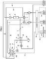
- FIG. 1 is a system diagram of a flow type analysis apparatus illustrated as a first embodiment of the present invention, which includes a one-way six-port four-position switching valve.
- the flow type analysis apparatus is used to analyze components of hemoglobin, including hemoglobin A1c in blood, using the technique of high performance liquid chromatography (HPLC). Accordingly, blood is used as the sample. In addition, a hemolysis process is necessary as a pretreatment, and a blood-dissolved solution is used. However, alternatively, a diluent with which hemolysis can be performed at the same time as dilution may be used, or further alternatively, a diluting and washing liquid may be used, which serves as both the above-described diluent and as a washing liquid.
- HPLC high performance liquid chromatography
- a carrier liquid reservoir tank 51,52 for storing a first carrier liquid and a second carrier liquid of different composition, including the type and the concentration of the solvent and the reagent to be added, for example, and a diluting and washing liquid reservoir tank 53 are connected via a common deaeration device 54.
- the first and the second carrier liquid reservoir tanks 51,52 and the diluting and washing liquid reservoir tank 53 may be designed as a kit as a reagent kit 50.
- the diluting and washing liquid reservoir tank 53 may be divided into separate reservoir tanks, i.e. , into a diluent tank 53a and a washing liquid tank 53b.
- the flow type analysis apparatus illustrated in FIG. 1 is constituted by liquid feed pumps 1,2 for feeding the first and the second carrier liquid from the reservoir 51,52, a mixer 3 for mixing the carrier liquid fed from the liquid feed pump 1,2, a pulse damper 4 which is in communication with the mixer 3 and configured to absorb pulsation, a flow path 5 in which the carrier liquid from the mixer 3 flows, a sample injection device (main body) 6 to which the flow path 5 is connected at an inlet port thereof, a flow path 7 in which the carrier liquid flows and connected to the sample injection device 6 at an out let port thereof, a column 8 and a detection unit 9 arranged in the flow path 7, and a drain flow path 10 disposed downstream thereof.
- the liquid feed pumps 1,2 are each a single plunger pump and each includes a check valve (one-way valve) at a suction port and a discharge port thereof, respectively.
- the liquid feed pumps 1,2 are a variable volume type pump of which the discharge volume can be changed by changing the stroke of the plunger, and thus, the flow rate ratio between the two liquid feed pumps 1,2 can be changed.
- the mixer 3 mixes a first carrier liquid from the liquid feed pump 1 and a second carrier liquid from the liquid feed pump 2 together. Specifically, the mixer 3 introduces two types of carrier liquids into a cylindrical container in a tangential direction to mix them together, and causes the mixed solution to be derived in the axial direction. Accordingly, by changing the flow rate ratio between the liquid feed pumps 1,2 and by mixing the carrier liquids by using the mixer 3, a carrier liquid having freely selected concentration at a level between the concentration of the first carrier liquid and that of the second carrier liquid (a gradient function) can be obtained.
- a pipe 19 is connected to the mixer 3, which is a pipe used for carrying out air bleeding and filling of the carrier liquid at the stage of preparation for operation of the apparatus. The pipe 19 is closed by a switching valve 16, which will be described later below, during a normal operation.
- the pulse damper 4 is a diaphragm type damper which is in communication with a space within the mixer 3, and absorbs pulsations that may occur due to the use of a single plunger pump as the liquid feed pumps 1,2 particularly for reducing the size of the apparatus.
- the sample injection device 6 includes a sample injection portion 22.
- the sample injection portion 22 is disposed between the flow path 5 for feeding the carrier liquid from the mixer 3 and the flow path 7 disposed on the downstream side thereof and is capable of injecting a sample into the carrier liquid by using the needle 27 by moving the needle 27 to a sample injection position.
- the sample injection device 6 includes a sample drawing portion (vessel holding portion) 39 arranged below the sample injection portion 22.
- the sample drawing portion 39 can draw the sample by using the needle 27 by moving the needle 27 to a sample drawing position. Accordingly, the sample drawn by the sample drawing portion 39 is to be injected into the carrier liquid in the sample injection portion 22.
- the drawing and the injection are carried out after connecting a measuring pump (sampling pump) 11 to a pipe 12 to the needle 27 via the switching valve 16.
- a hole for drawing and injecting the sample by using the needle 27 may be opened downward at the tip of the needle 27, or alternatively, it may be opened sideward on a side portion near the tip with the tip being closed.
- the sample injection device 6 is provided with a washing portion 33 for washing the needle 27, which portion being formed integrally with a housing of the sample injection portion 22 and arranged at a location between the sample injection portion 22 and the sample drawing portion 39.
- the washing portion 33 supplies a washing liquid to the needle 27 that has been moved to a washing position to carry out washing of the needle 27.
- the washing is carried out after connecting the measuring pump 11 to a pipe 13 from the diluting and washing liquid reservoir tank 53 via the switching valve 16 and drawing the washing liquid and then connecting the measuring pump 11 to the pipe 12 to the needle 27 via the switching valve 16.
- the washing liquid is recovered by using a drain pump (waste pump) 14 and is then discharged into a drain flow path 15.
- the column 8 is disposed in the carrier liquid flow path 7 arranged downstream of the sample injection device 6, and separates the components contained in the sample from each other.
- the detection unit 9 which is disposed on the downstream side of the column 8, detects the separated component and transmits a signal of the detected component to a data processing device (not illustrated). Results of the data processing by the data processing device are output as analysis results.
- the flow type analysis apparatus illustrated in FIG. 1 is provided with the switching valve 16, which can be positioned at either one of four positions a to d.
- the four positions a to d correspond to ports a to d, respectively, and a first in-valve flow path 16a, which is in communication with the measuring pump 11, is selectively connected to one of the ports a to d when the first in-valve flow path 16a is turned.
- another arc-like second in-valve flow path 16b is turned in accordance with the turning of the first in-valve flow path 16a, and the ports e and f are brought into communication with each other due to this motion of the arc-like second in-valve flow path 16b at positions a and b.
- the port a is connected to a cylinder chamber of the liquid feed pump 1 via a pipe 17 for bleeding of air and filling of the carrier liquid.
- the port b is connected to the cylinder chamber of the liquid feed pump 2 via a pipe 18 for bleeding of air and filling of the carrier liquid.
- the port c is connected to the needle 27 via the pipe 12.
- the port d is connected to the diluting and washing liquid reservoir tank 53 via the pipe 13.
- the port e is connected to the pipe 19 from the mixer 3 for bleeding of air and filling of the carrier liquid, and the port f is connected to a drain flow path 20.
- a rotor of the switching valve 16 is provided with a center pipe connection port at which the measuring pump 11 is connected, the first in-valve flow path 16a which is in communication with the center pipe connection port, and the arc-like second in-valve flow path 16b which turns in accordance with the turning of the first in-valve flow path 16a.
- a stator of the switching valve 16 is provided with a first pipe connection port group including the above-described ports a to d, and a second pipe connection port group including the above-described ports e and f.
- the first pipe connection port group (the ports a to d) is in communication with the center pipe connection port via the first in-valve flow path 16a individually in accordance with the turning of the first in-valve flow path 16a, and the positions of connection between the first in-valve flow path 16a and each of the ports a to d exist on the same circumference.
- the second pipe connection port group (the ports e and f) can be brought into communication with each other via the arc-like second in-valve flow path 16b in accordance with the turning of the arc-like second in-valve flow path 16b.
- the positions of connection between the arc-like second in-valve flow path 16b and each of the ports e and f exist on the circumference that is coaxial with the circumference on which the ports a to d exist, of which the diameter is different from that of the circumference on which the ports a to d exist.
- the two ports e and f of the second pipe connection port group are brought into communication by the arc-like second in-valve flow path 16b when the center pipe connection port is brought into communication with the port a or b.
- the two ports e and f of the second pipe connection port group are not brought into mutual communication by the arc-like second in-valve flow path 16b when the center pipe connection port is brought into communication with the port c or d.
- the air bleeding and the filling of the carrier liquid will be described below, which is carried out at the stage of preparation of operation of the flow type analysis apparatus illustrated in FIG. 1 .
- the following operations are carried out in an automatic operation mode to fill the inside of the flow path with the liquid by releasing air from the inside of the flow path.
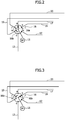
- the position of the switching valve 16 is switched to the position a (the state illustrated in FIGs. 1 and 2 ).
- the measuring pump 11 is connected to the port a (the pipe 17) and the port e and the port f are brought into communication with each other.
- the measuring pump 11 carries out the drawing operation. Then, the first carrier liquid in the reservoir tank 51 is fed through the check valve on the drawing side of the liquid feed pump 1, then through the pipe 17 from the cylinder chamber of the liquid feed pump 1 to be drawn into the measuring pump 11. In this manner, the flow paths from the reservoir tank 51 to the liquid feed pump 1 are filled with the carrier liquid.
- the measuring pump 11 carries out the discharge operation. Then the first carrier liquid is pumped from the measuring pump 11 into the liquid feed pump 1 via the pipe 17, and the check valve on the discharge side is opened to allow the carrier liquid flow to be fed into the mixer 3. Furthermore, the carrier liquid is then allowed to flow into the pipe 19 from the mixer 3 due to the resistance force from the column 8, and itis further discharged from the pipe 19 as a drain through the drain flow path 20 connected to the pipe 19 via the switching valve 16 (the ports e and f).
- the switching valve 16 is allowed to turn clockwise by 60° to position the switching valve 16 at the position b (a state illustrated in FIG. 3 ) .
- the measuring pump 11 is brought into communication with the port b (the pipe 18) and the ports e and f continue their mutual communication.
- the measuring pump 11 carries out the drawing operation. Then, the second carrier liquid in the reservoir tank 52 is fed through the check valve on the drawing side of the liquid feed pump 2, then is fed from the cylinder chamber of the liquid feed pump 2, to be drawn into the measuring pump 11 through the pipe 18. In the above-described manner, the flow paths from the second carrier liquid reservoir tank 52 to the liquid feed pump 2 are filled with the carrier liquid.
- the measuring pump 11 carries out the discharge operation. Then the second carrier liquid in the measuring pump 11 is pumped into the liquid feed pump 2 via the pipe 18, then the check valve on the discharge side is opened to allow the carrier liquid to flow into the mixer 3. Furthermore, the carrier liquid is then allowed to flow into the pipe 19 from the mixer 3 due to the resistance force from the column 8, and is further discharged from the pipe 19 as a drain through the drain flow path 20 connected to the pipe 19 via the switching valve 16 (the ports e and f).
- the switching valve 16 is moved to a position other than the positions a and b to start the feeding from the liquid feed pumps 1,2 and fill the carrier liquid flow paths 5 and 7 including the sample injection portion 22 and the column 8 and the detection unit 9 with the carrier liquid.
- a dilution step, a sample drawing step, a sample injection step, and a washing step carried out during a normal operation state of the flow type analysis apparatus illustrated in FIG. 1 will be descr ibed below.
- the needle 27 is positioned at a sample drawing position (the sample drawing portion 39), i .e. , at a position in an inside of a vessel containing the sample.
- the switching valve 16 For the position of the switching valve 16, the switching valve 16 is positioned at the position d first (a state illustrated in FIG. 5 ). At the position d, the measuring pump 11 is connected to the port d (the pipe 13). In this state, the measuring pump 11 carries out the drawing operation. Then the diluent (the diluting and washing liquid) in the reservoir tank 53 is drawn into the measuring pump 11 via the pipe 13.
- the diluent the diluting and washing liquid
- the position of the switching valve 16 is changed to the position c (a state illustrated in FIG. 4 ).
- the measuring pump 11 is connected to the port c (the pipe 12). In this state, the measuring pump 11 carries out the discharge operation. Then, the diluent in the measuring pump 11 is pumped into the needle 27 via the pipe 12.
- the needle 27 is positioned at the sample drawing position (the sample drawing portion 39), i .e. , at a position inside the container, and thus, the diluent is supplied into the vessel.
- the measuring pump 11 repeats the drawing operation and the discharge operation, and thus, the needle 27 draws and returns the mixed solution including the sample and the diluent in the vessel, and thereby, the mixed solution in the vessel is stirred and the sample is homogeneously diluted.
- the needle 27 is positioned at the sample drawing position (the sample drawing portion 39), i .e. , at a position inside the vessel containing the sample (the sample diluted with the diluent).
- the position of the switching valve 16 is set to the position c ( FIG. 4 ).
- the measuring pump 11 is connected to the port c (the pipe 12). In this state, the measuring pump 11 carries out the drawing operation. Then, the sample in the vessel is drawn into the needle 27.
- the needle 27 is positioned at the sample injection position (the sample injection portion 22).
- the position of the switching valve 16 is set to the position c ( FIG. 4 ).
- the measuring pump 11 is connected to the port c (the pipe 12). In this state, the measuring pump 11 carries out the discharge operation. Then, the sample in the needle 27 is injected into the sample injection portion 22 arranged between the carrier liquid flow paths 5 and 7.
- the needle 27 is positioned at the washing position (the washing portion 33).
- the position of the switching valve 16 is set to the position d ( FIG. 5 ) first.
- the measuring pump 11 is connected to the port d (the pipe 13). In this state, the measuring pump 11 carries out the drawing operation. Then, the washing liquid (the diluting and washing liquid) in the reservoir tank 53 is drawn into the measuring pump 11 via the pipe 13.
- the position of the switching valve 16 is set to the position c ( FIG. 4 ).
- the measuring pump 11 is connected to the port c (the pipe 12). In this state, the measuring pump 11 carries out the discharge operation. Then, the washing liquid in the measuring pump 11 is pumped into the needle 27 via the pipe 12. The needle 27 is positioned at the washing position, and the needle 27 is washed with the washing liquid there. After the washing, the washing liquid is recovered by the drain pump 14 and is then discharged through the drain flow path 15 as a drain.
- the washing liquid after the washing is discharged from the drain flow path 15 together with the air that entered through a guide hole (not illustrated) of the needle 27 without any leakage to the outside.
- the washing liquid is mixed with air to take the form of a mist, and thereby, the efficiency of the washing can be increased, the consumption of the washing liquid can be reduced, and accordingly, the washing of the needle 27 can be suitably carried out.
- a preparation step (the air bleeding and carrier liquid filling step) is carried out.
- the measuring pump 11 carries out the drawing and discharge operations with the switching valve 16 being positioned at the position a, then the switching valve 16 is positioned at the position b to carry out other drawing and discharge operations, and then, the switching valve 16 is moved to a position other than the position a or b to start the feeding from the liquid feed pumps 1,2, and thereby, the flow paths 5,7 including the sample injection portion 22 and the column 8 and the detection unit 9 are filled with the carrier liquid.
- a preliminary washing step (S1) is carried out. At this time, the needle 27 has been moved to the washing position.
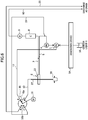
- FIG. 6 is a system diagram of a flow type analysis apparatus illustrated as a second embodiment of the present invention, which includes a one-way four-port two-position switching valve.
- the flow type analysis apparatus is used to carry out isocratic analysis for per forming analysis using the technique of HPLC and without changing the composition of the carrier liquid.
- the first carrier liquid reservoir tank 51 is connected to a flow type analysis apparatus via the deaeration device 54 illustrated in FIG. 6 .
- the flow type analysis apparatus illustrated in FIG. 6 includes a liquid feed pump 1 for feeding the first carrier liquid from the reservoir tank 51, the pulse damper 4 configured to absorb pulsation, the carrier liquid flow path 5, the sample injection device (main body) 6 to which the flow path 5 is connected at an inlet port thereof, a carrier liquid flow path 7 connected to the sample injection device 6 at an outlet port thereof, the column 8 and a detection unit 9 arranged in the flow path 7, and a drain flow path 10 disposed downstream thereof.
- the first carrier liquid feed pump 1 is a single plunger pump which includes a check valve (one-way valve) at a drawing por t and a discharge port thereof, respectively.
- the liquid feed pump 1 may be a variable volume type pump of which the discharge volume can be changed by changing the stroke of the plunger.
- the pipe 19 is connected to the flow path 5 for feeding the carrier liquid from 1, which is a pipe used in the air bleeding and filling of the liquid at the stage of preparation for operation of the apparatus. In a normal operation state of the apparatus (i .e. , during the sample drawing step and the sample injection step), the pipe 19 is closed by the switching valve 16, which will be described below.
- the pulse damper 4 is a diaphragm type damper which absorbs pulsations that may occur due to the use of a single plunger pump as the liquid feed pump 1.
- the sample injection device 6 includes a sample injection portion 22.
- the sample injection portion 22 is disposed between the flow path 5 for feeding the carrier liquid from the liquid feed pump 1 and the flow path 7 disposed on the downstream side thereof, and capable of injecting a sample into the carrier liquid by using the needle 27 by moving the needle 27 to a sample injection position.
- the sample injection device 6 includes a sample drawing portion (vessel holding portion) 39 arranged below the sample injection portion 22.
- the sample drawing portion 39 can draw the sample by using the needle 27 by moving the needle 27 to a sample drawing position. Accordingly, the sample drawn by the sample drawing portion 39 is to be injected into the carrier liquid in the sample injection portion 22. Note that the drawing and the injection are carried out after connecting a measuring pump 11 to a pipe 12 to the needle 27 via the switching valve 16.
- the column 8 is disposed in the carrier liquid flow path 7 arranged downstream of the sample injection device 6, and separates the components contained in the sample from one another.
- the detection unit 9 which is disposed on the downstream side of the column 8, detects the separated component and transmits a signal of the detected component to a data processing device (not illustrated). Results of the data processing by the data processing device are output as analysis results.
- the flow type analysis apparatus illustrated in FIG. 6 is provided with the switching valve 16, which can be positioned at either of two positions a and b.
- the two positions a and b correspond to ports a and b, respectively, and a first in-valve flow path 16a, which is in communication with the measuring pump 11, is selectively connected to one of the ports a and b when the first in-valve flow path 16a is turned.
- another arc-like second in-valve flow path 16b is turned in accordance with the turning of the first in-valve flow path 16a, and the ports c and d are brought into communication with each other due to this motion of the arc-like second in-valve flow path 16b at the position a.
- the port a is connected to a cylinder chamber of the liquid feed pump 1 via a pipe 17 for bleeding of air and filling of the carrier liquid.
- the port b is connected to the needle 27 via the pipe 12.
- the port c is connected to the pipe 19 for releasing of air and filling of the carrier liquid connected from the pulse damper 4.
- the port d is connected to the drain flow path 20.
- the ports a and b are equivalent to the first pipe connection port group and the ports c and d are equivalent to the second pipe connection port group.
- the following operations are carried out in an automatic operation mode to fill the inside of the flow path with the liquid by releasing air from the inside of the flow path.
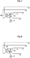
- the position of the switching valve 16 is switched to the position a (the state illustrated in FIGs. 6 and 7 ).
- the measuring pump 11 is connected to the port a (the pipe 17) and the port c and the port d are brought into communication with each other.
- the measuring pump 11 carries out the drawing operation. Then, the first carrier liquid in the reservoir tank 51 flows through the check valve on the drawing side of the liquid feed pump 1, then through the pipe 17 from the cylinder chamber of the liquid feed pump 1 to be drawn into the measuring pump 11. In this manner, the flow paths from the reservoir tank 51 to the liquid feed pump 1 are filled with the carrier liquid.
- the measuring pump 11 carries out the discharge operation. Then, the first carrier liquid is pumped from the measuring pump 11 into the liquid feed pump 1 via the pipe 17, and the check valve on the discharge side is opened to let the carrier liquid flow into the pulse damper 4. Furthermore, the carrier liquid is then allowed to flow into the pipe 19 from the pulse damper 4 due to the resistance force from the column 8, and because the pipe 19 is in communication with the drain flow path 20 via the switching valve 16 (the ports c and d), the carrier liquid is discharged from the drain flow path 20 as a drain.
- the needle 27 is positioned at the sample drawing position (the sample drawing portion 39), i .e. , at a position inside the vessel containing the sample.
- the position of the switching valve 16 is set to the position b ( FIG. 8 ).
- the measuring pump 11 is connected to the port b (the pipe 12). In this state, the measuring pump 11 carries out the drawing operation. Then, the sample in the vessel is drawn into the needle 27.
- the needle 27 is positioned at the sample injection position (the sample injection portion 22).
- the position of the switching valve 16 is switched to the position b ( FIG. 8 ).
- the measuring pump 11 is connected to the port b (the pipe 12). In this state, the measuring pump 11 carries out the discharge operation. Then, the sample in the needle 27 is injected into the sample injection portion 22 arranged between the carrier liquid flow paths 5 and 7.
- an apparatus for feeding the diluting and washing liquid is constituted by the measuring pump 11, and the measuring pump 11 can be connected selectively to an upper end portion of the needle 27 or the diluting and washing liquid reservoir tank 53, and the diluting and washing liquid having been drawn from the reservoir tank 53 when the switching valve 16 is positioned at one position (the position d) can be discharged and fed into the needle 27 when the switching valve 16 is positioned at another position (the position c), and thereby, the feeding of the diluting and washing liquid can be easily carried out, which makes the present invention highly useful.
- air bleeding can be suitably performed even with a small-size and low-volume plunger pump, with which air bleeding by the stroke of the plunger is difficult to perform, by using an air bleeding mechanism constituted by the connection between the measuring pump 11 and the cylinder chamber of the liquid feed pumps 1,2 (the cylinder chamber of the liquid feed pump 1 in the second embodiment) by using the switching valve 16, and thus, the plunger pump can be used as the configuration of the flow type analysis apparatus, and therefore, the present invention can contribute to reduction of the size of the flow type analysis apparatus.
- the flow path can be switched between the flow path for air bleeding and the flow path for normal operation due to the effect of switching of the flow path with the arc- like second in-valve flow path 16b included in the switching valve 16, and thus no drain valve is required, and therefore the present invention can contribute to reduction in the size of the flow type analysis apparatus.
- the hemoglobin component measurement method can contribute to increasing the accuracy and the speed of diabetes testing, in which method, blood is injected into the carrier liquid flow path as the sample, the hemoglobin components in the blood are separated and detected, and the amounts of the components thereof (hemoglobin A1c values, and the like) are measured.
- a known method can be used as a method for separating and detecting hemoglobin components in blood and measuring the component amount thereof.
- separation analysis performed according to standard liquid chromatography including a sample injection portion, a sample separation portion having a separation column, a detection portion, and the like, is well known to a person skilled in the art.
- the scope of application of the apparatus of the present invention is not limited to this.
- the switching valve for flow type analysis according to the present invention the flow type analysis apparatus which uses the switching valve, and the hemoglobin component measurement method can be suitably used for various types of analysis, and therefore, the industrial applicability is high.
Landscapes
- Health & Medical Sciences (AREA)
- Life Sciences & Earth Sciences (AREA)
- Physics & Mathematics (AREA)
- Chemical & Material Sciences (AREA)
- Engineering & Computer Science (AREA)
- General Health & Medical Sciences (AREA)
- General Physics & Mathematics (AREA)
- Immunology (AREA)
- Pathology (AREA)
- Biochemistry (AREA)
- Analytical Chemistry (AREA)
- Biomedical Technology (AREA)
- Hematology (AREA)
- Ecology (AREA)
- Biophysics (AREA)
- Molecular Biology (AREA)
- Urology & Nephrology (AREA)
- Food Science & Technology (AREA)
- Medicinal Chemistry (AREA)
- Sampling And Sample Adjustment (AREA)
- Automatic Analysis And Handling Materials Therefor (AREA)
- Multiple-Way Valves (AREA)
Applications Claiming Priority (3)
| Application Number | Priority Date | Filing Date | Title |
|---|---|---|---|
| JP2013089306 | 2013-04-22 | ||
| JP2013148183 | 2013-07-17 | ||
| PCT/JP2014/061256 WO2014175251A1 (ja) | 2013-04-22 | 2014-04-22 | フロー式分析装置用切換バルブ |
Publications (3)
| Publication Number | Publication Date |
|---|---|
| EP2990791A1 EP2990791A1 (en) | 2016-03-02 |
| EP2990791A4 EP2990791A4 (en) | 2017-01-04 |
| EP2990791B1 true EP2990791B1 (en) | 2018-03-21 |
Family
ID=51791823
Family Applications (1)
| Application Number | Title | Priority Date | Filing Date |
|---|---|---|---|
| EP14788272.4A Active EP2990791B1 (en) | 2013-04-22 | 2014-04-22 | Switching valve for a flow-type analysis device |
Country Status (5)
| Country | Link |
|---|---|
| US (1) | US9841406B2 (ja) |
| EP (1) | EP2990791B1 (ja) |
| JP (2) | JP5677649B1 (ja) |
| CN (1) | CN105324665B (ja) |
| WO (1) | WO2014175251A1 (ja) |
Families Citing this family (7)
| Publication number | Priority date | Publication date | Assignee | Title |
|---|---|---|---|---|
| US9752691B1 (en) * | 2014-07-03 | 2017-09-05 | Elemental Scientific, Inc. | Valve for controlled shuttle of liquid into microtiter plates and mixing |
| CN105044228B (zh) * | 2015-06-26 | 2017-04-12 | 山东省计量科学研究院 | 一种测量色谱柱柱容量的装置和方法 |
| CN105044272B (zh) * | 2015-06-26 | 2017-12-26 | 山东省计量科学研究院 | 一种快速测量离子色谱耐压能力的装置和方法 |
| US11413555B2 (en) * | 2017-05-10 | 2022-08-16 | Shimadzu Corporation | Liquid delivery device and liquid chromatograph equipped with liquid delivery device |
| CN108593407A (zh) * | 2018-03-13 | 2018-09-28 | 迈克医疗电子有限公司 | 样本稀释方法和装置、样本分析仪器及存储介质 |
| US11835496B2 (en) | 2019-12-23 | 2023-12-05 | Waters Technologies Corporation | Sample metering and injection for liquid chromatography |
| CN114247398A (zh) * | 2021-12-17 | 2022-03-29 | 沈磊 | 一种脂质纳米颗粒制备系统及设备 |
Family Cites Families (27)
| Publication number | Priority date | Publication date | Assignee | Title |
|---|---|---|---|---|
| US6779557B2 (en) | 2002-08-22 | 2004-08-24 | Mego Afek Industrial Measuring Instruments | Rotary disc valve |
| US4476017A (en) | 1983-06-03 | 1984-10-09 | Beckman Instruments, Inc. | Removable synthesis column |
| JPS6120861A (ja) * | 1984-07-09 | 1986-01-29 | Hitachi Ltd | 反応液体クロマトグラフ |
| JP2589997Y2 (ja) * | 1993-02-17 | 1999-02-03 | シスメックス株式会社 | サンプリングバルブ |
| US5803117A (en) | 1996-06-10 | 1998-09-08 | Rheodyne, L.P. | Multi-route full sweep selection valve |
| US6012487A (en) * | 1997-03-10 | 2000-01-11 | Brian A. Hauck | Prime purge injection valve or multi-route selections valve |
| JP3832055B2 (ja) * | 1997-11-20 | 2006-10-11 | 東ソー株式会社 | クロマトグラフ用流路切換えバルブ |
| FR2794836B1 (fr) * | 1999-06-09 | 2001-08-03 | Inst Francais Du Petrole | Vanne rotative amelioree |
| US6453946B2 (en) * | 2000-03-10 | 2002-09-24 | Rheodyne, Lp | Long lifetime fluid switching valve |
| JP2002031626A (ja) * | 2000-05-09 | 2002-01-31 | Tosoh Corp | 糖化ヘモグロビン分析計 |
| US6382035B1 (en) * | 2001-04-02 | 2002-05-07 | Rheodyne, Lp | Multi-valving sample injection apparatus |
| JP4644997B2 (ja) * | 2001-09-27 | 2011-03-09 | 株式会社島津製作所 | 送液ポンプシステム |
| US6672336B2 (en) * | 2001-11-28 | 2004-01-06 | Rheodyne, Lp | Dual random access, three-way rotary valve apparatus |
| CN101044346B (zh) * | 2004-08-25 | 2010-05-12 | 机械分析公司 | 回转阀及使用该回转阀的色谱分析系统 |
| WO2007051113A2 (en) * | 2005-10-27 | 2007-05-03 | Waters Investments Limited | Pump |
| JP4992401B2 (ja) * | 2006-12-06 | 2012-08-08 | 株式会社島津製作所 | オートサンプラ洗浄機構 |
| US8186382B2 (en) | 2007-02-22 | 2012-05-29 | Ge Healthcare Bio-Sciences Ab | Rotation valve for sample injection |
| EP2811210B1 (en) * | 2008-11-13 | 2017-08-02 | GE Healthcare Bio-Sciences AB | Random access rotary valve |
| EP2196801B1 (en) * | 2008-12-11 | 2017-08-23 | Spark Holland B.V. | Method and apparatus for injecting a liquid sample in an HPLC analyzing device, and valve assembly for use therein. |
| US8656955B2 (en) * | 2010-05-20 | 2014-02-25 | Bio-Rad Laboratories, Inc. | Rotary column selector valve |
| JP2012026893A (ja) * | 2010-07-23 | 2012-02-09 | Gl Sciences Inc | 液体クロマトグラフ |
| JP5646902B2 (ja) * | 2010-07-26 | 2014-12-24 | アークレイ株式会社 | 液体クロマトグラフィ装置およびインジェクションバルブ |
| JP5155365B2 (ja) * | 2010-07-27 | 2013-03-06 | 株式会社鷺宮製作所 | 空気調和機用排水ポンプ |
| JP5639914B2 (ja) * | 2011-02-02 | 2014-12-10 | ジーエルサイエンス株式会社 | 切換バルブ |
| US9228982B2 (en) * | 2011-09-16 | 2016-01-05 | Agilent Technologies, Inc. | Single injection valve for HPLC combining sample introduction, wash cycles and diagnosis |
| CN102808971B (zh) * | 2012-01-09 | 2014-09-03 | 加拿大博朗科技有限公司 | 一种流体选择阀 |
| JP5270771B2 (ja) * | 2012-02-03 | 2013-08-21 | 株式会社日立ハイテクノロジーズ | 液体クロマトグラフ装置及び試料導入装置 |
-
2014
- 2014-04-22 CN CN201480035677.7A patent/CN105324665B/zh active Active
- 2014-04-22 JP JP2014542629A patent/JP5677649B1/ja active Active
- 2014-04-22 EP EP14788272.4A patent/EP2990791B1/en active Active
- 2014-04-22 WO PCT/JP2014/061256 patent/WO2014175251A1/ja active Application Filing
- 2014-04-22 US US14/786,397 patent/US9841406B2/en active Active
- 2014-12-08 JP JP2014248267A patent/JP6309439B2/ja active Active
Non-Patent Citations (1)
| Title |
|---|
| None * |
Also Published As
| Publication number | Publication date |
|---|---|
| US20160061788A1 (en) | 2016-03-03 |
| US9841406B2 (en) | 2017-12-12 |
| EP2990791A4 (en) | 2017-01-04 |
| JP2015092166A (ja) | 2015-05-14 |
| CN105324665B (zh) | 2017-10-13 |
| CN105324665A (zh) | 2016-02-10 |
| WO2014175251A1 (ja) | 2014-10-30 |
| JP5677649B1 (ja) | 2015-02-25 |
| JP6309439B2 (ja) | 2018-04-11 |
| JPWO2014175251A1 (ja) | 2017-02-23 |
| EP2990791A1 (en) | 2016-03-02 |
Similar Documents
| Publication | Publication Date | Title |
|---|---|---|
| EP2990791B1 (en) | Switching valve for a flow-type analysis device | |
| EP3023782B1 (en) | Sample analysis device and gradient liquid feed device | |
| JP5111476B2 (ja) | 液体試料分析装置及び液体試料導入装置 | |
| JP2015092166A5 (ja) | ||
| JP6870741B2 (ja) | オートサンプラ及び液体クロマトグラフ | |
| JP5263197B2 (ja) | 液体クロマトグラフ用オートサンプラ | |
| JP7081722B2 (ja) | クロマトグラフシステム、オートサンプラおよび洗浄方法 | |
| CN103238066A (zh) | 液体色谱仪、液体色谱仪用试样导入装置以及液体色谱仪用试样导入装置的清洗方法 | |
| EP2980580B1 (en) | Sample-injection device for flow-analysis device, flow-analysis device, and method for measuring hemoglobin components | |
| WO2012005233A1 (ja) | 液体クロマトグラフ、および液体クロマトグラフ用送液装置 | |
| CN109944762B (zh) | 高效液相色谱仪的四通道二元高压泵系统 | |
| JP6130788B2 (ja) | 生化学分析用の試料注入装置、フロー式生化学分析装置、及び、ヘモグロビン成分の計測方法 | |
| JP2003014719A (ja) | 液体クロマトグラフ装置 | |
| CN103901144B (zh) | 自动进样器 | |
| EP2061420A1 (en) | Washing device for liquid chromatography injectors |
Legal Events
| Date | Code | Title | Description |
|---|---|---|---|
| PUAI | Public reference made under article 153(3) epc to a published international application that has entered the european phase |
Free format text: ORIGINAL CODE: 0009012 |
|
| 17P | Request for examination filed |
Effective date: 20151123 |
|
| AK | Designated contracting states |
Kind code of ref document: A1 Designated state(s): AL AT BE BG CH CY CZ DE DK EE ES FI FR GB GR HR HU IE IS IT LI LT LU LV MC MK MT NL NO PL PT RO RS SE SI SK SM TR |
|
| AX | Request for extension of the european patent |
Extension state: BA ME |
|
| DAX | Request for extension of the european patent (deleted) | ||
| RIN1 | Information on inventor provided before grant (corrected) |
Inventor name: TAIRA, HIROAKI Inventor name: MURAKI, HIDEKI Inventor name: OKA, TAKAYUKI Inventor name: YOTANI, TAKUYA |
|
| A4 | Supplementary search report drawn up and despatched |
Effective date: 20161201 |
|
| RIC1 | Information provided on ipc code assigned before grant |
Ipc: G01N 1/00 20060101ALI20161125BHEP Ipc: G01N 30/20 20060101ALI20161125BHEP Ipc: G01N 30/26 20060101AFI20161125BHEP Ipc: G01N 35/10 20060101ALN20161125BHEP |
|
| RIC1 | Information provided on ipc code assigned before grant |
Ipc: G01N 1/00 20060101ALI20170731BHEP Ipc: G01N 30/26 20060101AFI20170731BHEP Ipc: G01N 35/10 20060101ALN20170731BHEP Ipc: G01N 30/20 20060101ALI20170731BHEP |
|
| RIC1 | Information provided on ipc code assigned before grant |
Ipc: G01N 35/10 20060101ALN20170831BHEP Ipc: G01N 1/00 20060101ALI20170831BHEP Ipc: G01N 30/20 20060101ALI20170831BHEP Ipc: G01N 30/26 20060101AFI20170831BHEP |
|
| GRAP | Despatch of communication of intention to grant a patent |
Free format text: ORIGINAL CODE: EPIDOSNIGR1 |
|
| INTG | Intention to grant announced |
Effective date: 20171010 |
|
| RIN1 | Information on inventor provided before grant (corrected) |
Inventor name: MURAKI, HIDEKI Inventor name: TAIRA, HIROAKI Inventor name: OKA, TAKAYUKI Inventor name: YOTANI, TAKUYA |
|
| GRAS | Grant fee paid |
Free format text: ORIGINAL CODE: EPIDOSNIGR3 |
|
| GRAA | (expected) grant |
Free format text: ORIGINAL CODE: 0009210 |
|
| AK | Designated contracting states |
Kind code of ref document: B1 Designated state(s): AL AT BE BG CH CY CZ DE DK EE ES FI FR GB GR HR HU IE IS IT LI LT LU LV MC MK MT NL NO PL PT RO RS SE SI SK SM TR |
|
| REG | Reference to a national code |
Ref country code: GB Ref legal event code: FG4D |
|
| REG | Reference to a national code |
Ref country code: CH Ref legal event code: EP |
|
| REG | Reference to a national code |
Ref country code: AT Ref legal event code: REF Ref document number: 981663 Country of ref document: AT Kind code of ref document: T Effective date: 20180415 |
|
| REG | Reference to a national code |
Ref country code: IE Ref legal event code: FG4D |
|
| REG | Reference to a national code |
Ref country code: DE Ref legal event code: R096 Ref document number: 602014022693 Country of ref document: DE |
|
| REG | Reference to a national code |
Ref country code: FR Ref legal event code: PLFP Year of fee payment: 5 |
|
| REG | Reference to a national code |
Ref country code: SE Ref legal event code: TRGR |
|
| REG | Reference to a national code |
Ref country code: NL Ref legal event code: MP Effective date: 20180321 |
|
| PG25 | Lapsed in a contracting state [announced via postgrant information from national office to epo] |
Ref country code: CY Free format text: LAPSE BECAUSE OF FAILURE TO SUBMIT A TRANSLATION OF THE DESCRIPTION OR TO PAY THE FEE WITHIN THE PRESCRIBED TIME-LIMIT Effective date: 20180321 Ref country code: HR Free format text: LAPSE BECAUSE OF FAILURE TO SUBMIT A TRANSLATION OF THE DESCRIPTION OR TO PAY THE FEE WITHIN THE PRESCRIBED TIME-LIMIT Effective date: 20180321 Ref country code: LT Free format text: LAPSE BECAUSE OF FAILURE TO SUBMIT A TRANSLATION OF THE DESCRIPTION OR TO PAY THE FEE WITHIN THE PRESCRIBED TIME-LIMIT Effective date: 20180321 |
|
| REG | Reference to a national code |
Ref country code: LT Ref legal event code: MG4D |
|
| REG | Reference to a national code |
Ref country code: AT Ref legal event code: MK05 Ref document number: 981663 Country of ref document: AT Kind code of ref document: T Effective date: 20180321 |
|
| REG | Reference to a national code |
Ref country code: NO Ref legal event code: T2 Effective date: 20180321 |
|
| PG25 | Lapsed in a contracting state [announced via postgrant information from national office to epo] |
Ref country code: GR Free format text: LAPSE BECAUSE OF FAILURE TO SUBMIT A TRANSLATION OF THE DESCRIPTION OR TO PAY THE FEE WITHIN THE PRESCRIBED TIME-LIMIT Effective date: 20180622 Ref country code: LV Free format text: LAPSE BECAUSE OF FAILURE TO SUBMIT A TRANSLATION OF THE DESCRIPTION OR TO PAY THE FEE WITHIN THE PRESCRIBED TIME-LIMIT Effective date: 20180321 Ref country code: RS Free format text: LAPSE BECAUSE OF FAILURE TO SUBMIT A TRANSLATION OF THE DESCRIPTION OR TO PAY THE FEE WITHIN THE PRESCRIBED TIME-LIMIT Effective date: 20180321 Ref country code: BG Free format text: LAPSE BECAUSE OF FAILURE TO SUBMIT A TRANSLATION OF THE DESCRIPTION OR TO PAY THE FEE WITHIN THE PRESCRIBED TIME-LIMIT Effective date: 20180621 |
|
| PG25 | Lapsed in a contracting state [announced via postgrant information from national office to epo] |
Ref country code: NL Free format text: LAPSE BECAUSE OF FAILURE TO SUBMIT A TRANSLATION OF THE DESCRIPTION OR TO PAY THE FEE WITHIN THE PRESCRIBED TIME-LIMIT Effective date: 20180321 Ref country code: ES Free format text: LAPSE BECAUSE OF FAILURE TO SUBMIT A TRANSLATION OF THE DESCRIPTION OR TO PAY THE FEE WITHIN THE PRESCRIBED TIME-LIMIT Effective date: 20180321 Ref country code: PL Free format text: LAPSE BECAUSE OF FAILURE TO SUBMIT A TRANSLATION OF THE DESCRIPTION OR TO PAY THE FEE WITHIN THE PRESCRIBED TIME-LIMIT Effective date: 20180321 Ref country code: AL Free format text: LAPSE BECAUSE OF FAILURE TO SUBMIT A TRANSLATION OF THE DESCRIPTION OR TO PAY THE FEE WITHIN THE PRESCRIBED TIME-LIMIT Effective date: 20180321 Ref country code: RO Free format text: LAPSE BECAUSE OF FAILURE TO SUBMIT A TRANSLATION OF THE DESCRIPTION OR TO PAY THE FEE WITHIN THE PRESCRIBED TIME-LIMIT Effective date: 20180321 Ref country code: EE Free format text: LAPSE BECAUSE OF FAILURE TO SUBMIT A TRANSLATION OF THE DESCRIPTION OR TO PAY THE FEE WITHIN THE PRESCRIBED TIME-LIMIT Effective date: 20180321 |
|
| PG25 | Lapsed in a contracting state [announced via postgrant information from national office to epo] |
Ref country code: CZ Free format text: LAPSE BECAUSE OF FAILURE TO SUBMIT A TRANSLATION OF THE DESCRIPTION OR TO PAY THE FEE WITHIN THE PRESCRIBED TIME-LIMIT Effective date: 20180321 Ref country code: AT Free format text: LAPSE BECAUSE OF FAILURE TO SUBMIT A TRANSLATION OF THE DESCRIPTION OR TO PAY THE FEE WITHIN THE PRESCRIBED TIME-LIMIT Effective date: 20180321 Ref country code: SM Free format text: LAPSE BECAUSE OF FAILURE TO SUBMIT A TRANSLATION OF THE DESCRIPTION OR TO PAY THE FEE WITHIN THE PRESCRIBED TIME-LIMIT Effective date: 20180321 Ref country code: SK Free format text: LAPSE BECAUSE OF FAILURE TO SUBMIT A TRANSLATION OF THE DESCRIPTION OR TO PAY THE FEE WITHIN THE PRESCRIBED TIME-LIMIT Effective date: 20180321 |
|
| REG | Reference to a national code |
Ref country code: BE Ref legal event code: MM Effective date: 20180430 |
|
| PG25 | Lapsed in a contracting state [announced via postgrant information from national office to epo] |
Ref country code: PT Free format text: LAPSE BECAUSE OF FAILURE TO SUBMIT A TRANSLATION OF THE DESCRIPTION OR TO PAY THE FEE WITHIN THE PRESCRIBED TIME-LIMIT Effective date: 20180723 |
|
| REG | Reference to a national code |
Ref country code: DE Ref legal event code: R097 Ref document number: 602014022693 Country of ref document: DE |
|
| REG | Reference to a national code |
Ref country code: IE Ref legal event code: MM4A |
|
| PLBE | No opposition filed within time limit |
Free format text: ORIGINAL CODE: 0009261 |
|
| STAA | Information on the status of an ep patent application or granted ep patent |
Free format text: STATUS: NO OPPOSITION FILED WITHIN TIME LIMIT |
|
| PG25 | Lapsed in a contracting state [announced via postgrant information from national office to epo] |
Ref country code: MC Free format text: LAPSE BECAUSE OF FAILURE TO SUBMIT A TRANSLATION OF THE DESCRIPTION OR TO PAY THE FEE WITHIN THE PRESCRIBED TIME-LIMIT Effective date: 20180321 Ref country code: DK Free format text: LAPSE BECAUSE OF FAILURE TO SUBMIT A TRANSLATION OF THE DESCRIPTION OR TO PAY THE FEE WITHIN THE PRESCRIBED TIME-LIMIT Effective date: 20180321 Ref country code: LU Free format text: LAPSE BECAUSE OF NON-PAYMENT OF DUE FEES Effective date: 20180422 |
|
| 26N | No opposition filed |
Effective date: 20190102 |
|
| PG25 | Lapsed in a contracting state [announced via postgrant information from national office to epo] |
Ref country code: BE Free format text: LAPSE BECAUSE OF NON-PAYMENT OF DUE FEES Effective date: 20180430 |
|
| PG25 | Lapsed in a contracting state [announced via postgrant information from national office to epo] |
Ref country code: IE Free format text: LAPSE BECAUSE OF NON-PAYMENT OF DUE FEES Effective date: 20180422 |
|
| PG25 | Lapsed in a contracting state [announced via postgrant information from national office to epo] |
Ref country code: SI Free format text: LAPSE BECAUSE OF FAILURE TO SUBMIT A TRANSLATION OF THE DESCRIPTION OR TO PAY THE FEE WITHIN THE PRESCRIBED TIME-LIMIT Effective date: 20180321 |
|
| PG25 | Lapsed in a contracting state [announced via postgrant information from national office to epo] |
Ref country code: MT Free format text: LAPSE BECAUSE OF NON-PAYMENT OF DUE FEES Effective date: 20180422 |
|
| PG25 | Lapsed in a contracting state [announced via postgrant information from national office to epo] |
Ref country code: TR Free format text: LAPSE BECAUSE OF FAILURE TO SUBMIT A TRANSLATION OF THE DESCRIPTION OR TO PAY THE FEE WITHIN THE PRESCRIBED TIME-LIMIT Effective date: 20180321 |
|
| PG25 | Lapsed in a contracting state [announced via postgrant information from national office to epo] |
Ref country code: MK Free format text: LAPSE BECAUSE OF NON-PAYMENT OF DUE FEES Effective date: 20180321 Ref country code: HU Free format text: LAPSE BECAUSE OF FAILURE TO SUBMIT A TRANSLATION OF THE DESCRIPTION OR TO PAY THE FEE WITHIN THE PRESCRIBED TIME-LIMIT; INVALID AB INITIO Effective date: 20140422 |
|
| PG25 | Lapsed in a contracting state [announced via postgrant information from national office to epo] |
Ref country code: IS Free format text: LAPSE BECAUSE OF FAILURE TO SUBMIT A TRANSLATION OF THE DESCRIPTION OR TO PAY THE FEE WITHIN THE PRESCRIBED TIME-LIMIT Effective date: 20180721 |
|
| PGFP | Annual fee paid to national office [announced via postgrant information from national office to epo] |
Ref country code: FR Payment date: 20230309 Year of fee payment: 10 |
|
| PGFP | Annual fee paid to national office [announced via postgrant information from national office to epo] |
Ref country code: SE Payment date: 20230227 Year of fee payment: 10 Ref country code: IT Payment date: 20230310 Year of fee payment: 10 |
|
| P01 | Opt-out of the competence of the unified patent court (upc) registered |
Effective date: 20230522 |
|
| PGFP | Annual fee paid to national office [announced via postgrant information from national office to epo] |
Ref country code: NO Payment date: 20230412 Year of fee payment: 10 Ref country code: DE Payment date: 20230228 Year of fee payment: 10 Ref country code: CH Payment date: 20230501 Year of fee payment: 10 |
|
| PGFP | Annual fee paid to national office [announced via postgrant information from national office to epo] |
Ref country code: FI Payment date: 20230411 Year of fee payment: 10 |
|
| PGFP | Annual fee paid to national office [announced via postgrant information from national office to epo] |
Ref country code: GB Payment date: 20240229 Year of fee payment: 11 |