EP2990258B1 - Position detection device, position detection method and moving body system - Google Patents
Position detection device, position detection method and moving body system Download PDFInfo
- Publication number
- EP2990258B1 EP2990258B1 EP14787645.2A EP14787645A EP2990258B1 EP 2990258 B1 EP2990258 B1 EP 2990258B1 EP 14787645 A EP14787645 A EP 14787645A EP 2990258 B1 EP2990258 B1 EP 2990258B1
- Authority
- EP
- European Patent Office
- Prior art keywords
- motor
- controller
- detection sensor
- drive
- magnet
- Prior art date
- Legal status (The legal status is an assumption and is not a legal conclusion. Google has not performed a legal analysis and makes no representation as to the accuracy of the status listed.)
- Active
Links
Images


Classifications
-
- H—ELECTRICITY
- H02—GENERATION; CONVERSION OR DISTRIBUTION OF ELECTRIC POWER
- H02K—DYNAMO-ELECTRIC MACHINES
- H02K41/00—Propulsion systems in which a rigid body is moved along a path due to dynamo-electric interaction between the body and a magnetic field travelling along the path
- H02K41/02—Linear motors; Sectional motors
- H02K41/03—Synchronous motors; Motors moving step by step; Reluctance motors
- H02K41/031—Synchronous motors; Motors moving step by step; Reluctance motors of the permanent magnet type
-
- B—PERFORMING OPERATIONS; TRANSPORTING
- B60—VEHICLES IN GENERAL
- B60L—PROPULSION OF ELECTRICALLY-PROPELLED VEHICLES; SUPPLYING ELECTRIC POWER FOR AUXILIARY EQUIPMENT OF ELECTRICALLY-PROPELLED VEHICLES; ELECTRODYNAMIC BRAKE SYSTEMS FOR VEHICLES IN GENERAL; MAGNETIC SUSPENSION OR LEVITATION FOR VEHICLES; MONITORING OPERATING VARIABLES OF ELECTRICALLY-PROPELLED VEHICLES; ELECTRIC SAFETY DEVICES FOR ELECTRICALLY-PROPELLED VEHICLES
- B60L15/00—Methods, circuits, or devices for controlling the traction-motor speed of electrically-propelled vehicles
- B60L15/002—Methods, circuits, or devices for controlling the traction-motor speed of electrically-propelled vehicles for control of propulsion for monorail vehicles, suspension vehicles or rack railways; for control of magnetic suspension or levitation for vehicles for propulsion purposes
- B60L15/005—Methods, circuits, or devices for controlling the traction-motor speed of electrically-propelled vehicles for control of propulsion for monorail vehicles, suspension vehicles or rack railways; for control of magnetic suspension or levitation for vehicles for propulsion purposes for control of propulsion for vehicles propelled by linear motors
-
- G—PHYSICS
- G01—MEASURING; TESTING
- G01D—MEASURING NOT SPECIALLY ADAPTED FOR A SPECIFIC VARIABLE; ARRANGEMENTS FOR MEASURING TWO OR MORE VARIABLES NOT COVERED IN A SINGLE OTHER SUBCLASS; TARIFF METERING APPARATUS; MEASURING OR TESTING NOT OTHERWISE PROVIDED FOR
- G01D5/00—Mechanical means for transferring the output of a sensing member; Means for converting the output of a sensing member to another variable where the form or nature of the sensing member does not constrain the means for converting; Transducers not specially adapted for a specific variable
- G01D5/12—Mechanical means for transferring the output of a sensing member; Means for converting the output of a sensing member to another variable where the form or nature of the sensing member does not constrain the means for converting; Transducers not specially adapted for a specific variable using electric or magnetic means
- G01D5/14—Mechanical means for transferring the output of a sensing member; Means for converting the output of a sensing member to another variable where the form or nature of the sensing member does not constrain the means for converting; Transducers not specially adapted for a specific variable using electric or magnetic means influencing the magnitude of a current or voltage
- G01D5/20—Mechanical means for transferring the output of a sensing member; Means for converting the output of a sensing member to another variable where the form or nature of the sensing member does not constrain the means for converting; Transducers not specially adapted for a specific variable using electric or magnetic means influencing the magnitude of a current or voltage by varying inductance, e.g. by a movable armature
-
- H—ELECTRICITY
- H02—GENERATION; CONVERSION OR DISTRIBUTION OF ELECTRIC POWER
- H02K—DYNAMO-ELECTRIC MACHINES
- H02K11/00—Structural association of dynamo-electric machines with electric components or with devices for shielding, monitoring or protection
- H02K11/20—Structural association of dynamo-electric machines with electric components or with devices for shielding, monitoring or protection for measuring, monitoring, testing, protecting or switching
- H02K11/21—Devices for sensing speed or position, or actuated thereby
- H02K11/215—Magnetic effect devices, e.g. Hall-effect or magneto-resistive elements
-
- B—PERFORMING OPERATIONS; TRANSPORTING
- B60—VEHICLES IN GENERAL
- B60L—PROPULSION OF ELECTRICALLY-PROPELLED VEHICLES; SUPPLYING ELECTRIC POWER FOR AUXILIARY EQUIPMENT OF ELECTRICALLY-PROPELLED VEHICLES; ELECTRODYNAMIC BRAKE SYSTEMS FOR VEHICLES IN GENERAL; MAGNETIC SUSPENSION OR LEVITATION FOR VEHICLES; MONITORING OPERATING VARIABLES OF ELECTRICALLY-PROPELLED VEHICLES; ELECTRIC SAFETY DEVICES FOR ELECTRICALLY-PROPELLED VEHICLES
- B60L13/00—Electric propulsion for monorail vehicles, suspension vehicles or rack railways; Magnetic suspension or levitation for vehicles
- B60L13/03—Electric propulsion by linear motors
-
- G—PHYSICS
- G01—MEASURING; TESTING
- G01D—MEASURING NOT SPECIALLY ADAPTED FOR A SPECIFIC VARIABLE; ARRANGEMENTS FOR MEASURING TWO OR MORE VARIABLES NOT COVERED IN A SINGLE OTHER SUBCLASS; TARIFF METERING APPARATUS; MEASURING OR TESTING NOT OTHERWISE PROVIDED FOR
- G01D5/00—Mechanical means for transferring the output of a sensing member; Means for converting the output of a sensing member to another variable where the form or nature of the sensing member does not constrain the means for converting; Transducers not specially adapted for a specific variable
- G01D5/12—Mechanical means for transferring the output of a sensing member; Means for converting the output of a sensing member to another variable where the form or nature of the sensing member does not constrain the means for converting; Transducers not specially adapted for a specific variable using electric or magnetic means
- G01D5/14—Mechanical means for transferring the output of a sensing member; Means for converting the output of a sensing member to another variable where the form or nature of the sensing member does not constrain the means for converting; Transducers not specially adapted for a specific variable using electric or magnetic means influencing the magnitude of a current or voltage
- G01D5/142—Mechanical means for transferring the output of a sensing member; Means for converting the output of a sensing member to another variable where the form or nature of the sensing member does not constrain the means for converting; Transducers not specially adapted for a specific variable using electric or magnetic means influencing the magnitude of a current or voltage using Hall-effect devices
- G01D5/145—Mechanical means for transferring the output of a sensing member; Means for converting the output of a sensing member to another variable where the form or nature of the sensing member does not constrain the means for converting; Transducers not specially adapted for a specific variable using electric or magnetic means influencing the magnitude of a current or voltage using Hall-effect devices influenced by the relative movement between the Hall device and magnetic fields
-
- Y—GENERAL TAGGING OF NEW TECHNOLOGICAL DEVELOPMENTS; GENERAL TAGGING OF CROSS-SECTIONAL TECHNOLOGIES SPANNING OVER SEVERAL SECTIONS OF THE IPC; TECHNICAL SUBJECTS COVERED BY FORMER USPC CROSS-REFERENCE ART COLLECTIONS [XRACs] AND DIGESTS
- Y02—TECHNOLOGIES OR APPLICATIONS FOR MITIGATION OR ADAPTATION AGAINST CLIMATE CHANGE
- Y02T—CLIMATE CHANGE MITIGATION TECHNOLOGIES RELATED TO TRANSPORTATION
- Y02T10/00—Road transport of goods or passengers
- Y02T10/60—Other road transportation technologies with climate change mitigation effect
- Y02T10/64—Electric machine technologies in electromobility
Definitions
- the present invention relates to a position detection device for detecting the position of a moving body moving on a movement path, a position detection method, and a moving body system.
- the moving body systems using linear motors are those using secondary-side-on-ground type linear motors.
- the secondary-side-on-ground type is a type in which linear motors are mounted on a mover (moving body) and magnets are disposed on a stator (rail).
- a moving body system of this type for example, there is known a moving body system in which magnets with south poles and magnets with north poles are alternately disposed on a rail (movement path) and a moving body having linear motors mounted thereon moves along the rail, as disclosed in Patent Literature 1.
- the moving body includes a position detector that detects the poles of magnets. The continuous positions of the moving body are determined based on detection results obtained by the position detector.
- Patent Literature 1 Japanese Unexamined Patent Application Publication No. 2006-27421
- the second position detector may detect the position of the moving body by detecting the poles of the magnets.
- the controller may determine that one of the first position detector and second position detector is located in the irregular section, by comparing a position detected by the first position detector and the position detected by the second position detector.
- the controller may determine a moving distance of the moving body in the irregular section on the basis of the position detected by the second position detector and may determine the position of the moving body on the basis of the determined moving distance.
- the irregular section may be a section in which the magnets are not disposed.
- the irregular section may also be a section in which the magnets with south poles and magnets with north poles are not alternately disposed.
- the irregular section may be shorter than a distance between the first position detector and second position detector in the moving direction.
- the present invention also provides a moving body system including a movement path on which magnets with south poles and magnets with north poles are alternately disposed and a moving body capable of moving along the movement path.
- the moving body includes the above position detection device.
- the controller determines the position of the moving body on the basis of the position detected by the second position detector.
- the second position detector detects the position of the moving body by detecting the poles of the magnets.
- the controller determines that one of the first position detector and second position detector is located in the irregular section, by comparing a position detected by the first position detector and the position detected by the second position detector. Thus, it is possible to reliably determine that one of the first position detector and second position detector is located in an irregular section.
- irregular sections include a section in which no magnet is disposed. Thus, it is possible to reliably determine the position of the moving body even in a section in which no magnet is disposed. Further, irregular sections include a section in which magnets with south poles and magnets with north poles are not alternately disposed. Thus, it is possible to reliably determine the position of the moving body even in a section in which magnets with south poles and magnets with north poles are not alternately disposed.
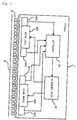
- Fig. 1 is a block diagram showing a moving body system according to the present embodiment.
- the moving body system shown in Fig. 1 is a system using secondary-side-on-ground type linear motors.
- This moving body system includes a vehicle 1 serving as a moving body and a rail 2 serving as the movement path of the moving body. Magnets 3 with north poles and magnets 3 with south poles are alternately disposed in a row with a predetermined pitch on the rail 2.
- the moving body system shown in Fig. 1 is, for example, a ceiling traveling vehicle system in which a vehicle 1 travels along a rail 2 installed on the ceiling. In the present embodiment, it is assumed that the moving body system includes a rail 2 having a length of several km and 300 to 400 vehicles 1.
- the moving body of the present embodiment is not limited to the vehicle 1 and may be any vehicles other than the vehicle 1 or moving bodies such as a robot arm.
- the first motor 10A and second motor 10B are linear motors which change the magnetic field so that the magnets 3 with south poles and magnets 3 with north poles alternately disposed on the rail 2 and the electrical angle thereof are synchronized.
- three-phase (U, V, and W phases) linear synchronous motors are used as the linear motors.
- the first motor 10A and second motor 10B are disposed in different positions in the moving direction of the vehicle 1 (in the direction of the rail 2 shown in Fig. 1 ).
- the first motor 10A and second motor 10B are disposed in positions which are opposed to magnets 3 on the rail 2 in the vehicle 1 and which are adjacent to the magnets 3.
- the first motor 10A is disposed in a front position in the moving direction of the vehicle 1, and the second motor 10B is disposed in a rear position in the moving direction of the vehicle 1.
- the front in the moving direction is referred to as front, and the rear in the moving direction is referred to as rear.
- the first magnet absence detection sensor 11A and second magnet absence detection sensor 11B are detectors which detect the magnets 3 on the rail 2.
- the first magnet absence detection sensor 11A is a detector for detecting that the first motor 10A is located in a section in which no magnet 3 is disposed on the rail 2 (an irregular section shown in Fig. 3 ).
- the second magnet absence detection sensor 11B is a detector for detecting that the second motor 10B is located in a section in which no magnet 3 is disposed on the rail 2 (the irregular section shown in Fig. 3 ).
- the first magnet absence detection sensor 11A and second magnet absence detection sensor 11B include, for example, photosensors that detect objects (the magnets 3 with south poles and magnets 3 with north poles in Fig. 1 ) by receiving light emitted by a light emitter using a light receiver.
- the first magnet absence detection sensor 11A and second magnet absence detection sensor 11B are also disposed in positions which are opposed to magnets 3 on the rail 2 in the vehicle 1 and which are adjacent to the magnets 3.
- the first magnet absence detection sensor 11A and the second magnet absence detection sensor 11B output detection signals to the controller 13.
- the first position detection sensor 12A and the second position detection sensor 12B are position detectors which detect the position of the vehicle 1 on the rail 2.
- the position of the vehicle 1 is determined based on a position detected by the first position detection sensor 12A.
- the position of the vehicle 1 is determined based on a position detected by the second position detection sensor 12B.
- the first position detection sensor 12A and the second position detection sensor 12B include, for example, magnetic pole detection sensors using Hall-effect devices (magnetic conversion devices; hereafter simply referred to as "Hall devices").
- the detection heads of the first position detection sensor 12A and the second position detection sensor 12B are provided with Hall devices. When the detection heads move relatively to the magnets 3 with the movement of the vehicle 1, the direction of the magnetic field with respect to the magnetosensitive surfaces of the Hall devices changes. The Hall devices output electrical signals corresponding to the changed angle. The position of the vehicle 1 on the rail 2 is detected based on the values (voltage values) of the electrical signals.
- the first position detection sensor 12A and the second position detection sensor 12B are also disposed in positions which are opposed to magnets 3 on the rail 2 in the vehicle 1 and which are adjacent to the magnets 3.
- the first position detection sensor 12A and the second position detection sensor 12B output detection signals to the controller 13.
- the controller 13 determines whether the first motor 10A is located in an irregular section, on the basis of the detection signal from the first magnet absence detection sensor 11A. If the controller 13 determines that the first motor 10A is not located in any irregular section, it outputs, to the drive controller 14, a drive command instructing the drive controller 14 to drive the first motor 10A. In contrast, if the controller 13 determines that the first motor 10A is located in an irregular section, it outputs, to the drive controller 14, a drive command instructing the drive controller 14 to stop the drive of the first motor 10A. Similarly, the controller 13 determines whether the second motor 10B is located in an irregular section, on the basis of the detection signal from the second magnet absence detection sensor 11B.
- the controller 13 determines that the second motor 10B is not located in any irregular section, it outputs, to the drive controller 14, a drive command instructing the drive controller 14 to drive the second motor 10B. In contrast, if the controller 13 determines that the second motor 10B is located in an irregular section, it outputs, to the drive controller 14, a drive command instructing the drive controller 14 to stop the drive of the second motor 10B. As shown in Fig. 6 , when the signal level of the drive command is high, the motor 10A or 10B is driven; when the signal level thereof is low, the motor 10A or 10B is stopped.
- the controller 13 determines the position of the vehicle 1 on the basis of the detection signal from the first position detection sensor 12A. In contrast, when the first position detection sensor 12A is located in an irregular section, the controller 13 determines the position of the vehicle 1 on the basis of the detection signal from the second position detection sensor 12B. Then, based on the determined position of the vehicle 1, the controller 13 outputs, to the drive controller 14, a position command instructing the drive controller 14 to move the vehicle 1 to a movement position.
- the drive controller 14 controls the drive or stop of the first motor 10A on the basis of the drive command related to the first motor 10A from the controller 13.
- the drive controller 14 also controls the drive or stop of the second motor 10B on the basis of the drive command related to the second motor 10B from the controller 13.
- the drive controller 14 also controls the drive of the first motor 10A and second motor 10B so that the vehicle 1 moves to the movement position, on the basis of the position command from the controller 13.
- first magnet absence detection sensor 11A and the first position detection sensor 12A are disposed in positions adjacent to the first motor 10A in the example shown in Fig. 1 , these sensors need not necessarily be disposed in such positions.
- second magnet absence detection sensor 11B and the second position detection sensor 12B are disposed in positions adjacent to the second motor 10B, these sensors need not necessarily be disposed in such positions.
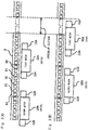
- Fig. 2 is a block diagram showing the internal configurations of the controller and drive controller.
- the controller 13 shown in Fig. 1 includes a position controller 131, a magnetless controller 132, and a motion controller 133.
- the drive controller 14 shown in Fig. 1 includes a first drive controller 14A that controls the drive of the first motor 10A and a second drive controller 14B that controls the drive of the second motor 10B.
- MMD shown in Fig. 2 represents a magnetless detect, that is, the magnet absence detection sensor 11A or 11B.
- PS shown in Fig. 2 represents a position sensor, that is, the position detection sensor 12A or 12B.
- the position controller 131 determines whether the first motor 10A is located in an irregular section, on the basis of the detection signal from the first magnet absence detection sensor 11A. If the position controller 131 determines that the first motor 10A is not located in any irregular section, it outputs a magnet absence detection status signal ("MLD-status" in Fig. 2 ) indicating this status, to the magnetless controller 132 and motion controller 133. The position controller 131 also determines whether the second motor 10B is located in an irregular section, on the basis of the detection signal from the second magnet absence detection sensor 11B. If the position controller 131 determines that the second motor 10B is not located in any irregular section, it outputs a magnet absence detection signal indicating this status, to the magnetless controller 132 and motion controller 133.
- MLD-status magnet absence detection status signal
- the position controller 131 determines the position of the vehicle 1 on the basis of the detection signal from the first position detection sensor 12A. In contrast, when the first position detection sensor 12A is located in an irregular section, the position controller 131 determines the position of the vehicle 1 on the basis of the detection signal from the second position detection sensor 12B. The position controller 131 then outputs position information indicating the determined current position of the vehicle 1 to the motion controller 133, first drive controller 14A, and second drive controller 14B.
- the motion controller 133 determines whether the first motor 10A and second motor 10B are located in an irregular section, on the basis of the magnet absence detection signals from the position controller 131. The motion controller 133 also checks the current position of the vehicle 1 on the basis of the position information from the position controller 131. The motion controller 133 then outputs, to the drive controller 14A or 14B of the motor 10A or 10B which is not located in any irregular section, a position command instructing the drive controller to move the vehicle 1 to a predetermined position (the movement position to which the vehicle 1 is to be moved).
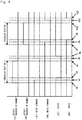
- the length of the rail 2 must be an integral multiple of that of a magnet unit 3U.
- an irregular section in which no magnet 3 is disposed would easily occur on the rail 2. Further, the generated irregular section would have a long length. In the example shown in Fig. 3 , there is generated an irregular section corresponding to about twice the pitch of a magnet.
- both the first magnet absence detection sensor 11A and second magnet absence detection sensor 11B have yet to enter the irregular section. Accordingly, both the first motor 10A and second motor 10B are being driven.
- the second magnet absence detection sensor 11B has yet to enter the irregular section, whereas the first magnet absence detection sensor 11A has entered the irregular section. Accordingly, only the second motor 10B is being driven, and the first motor 10A is not being driven (that is, the drive of the first magnet absence detection sensor 11A is being stopped). Subsequently, when the vehicle 1 moves in the traveling direction, the second magnet absence detection sensor 11B enters the irregular section. In this case, the drive of the second motor 10B is stopped.
- an "irregular section” refers to a section in which the poles of magnets are not disposed regularly, that is, a section in which magnets 31 with north poles and magnets 32 with south poles are not disposed regularly. Accordingly, “irregular sections” include sections in which no magnet 3 is disposed, as well as sections in which magnets 31 with north poles and magnets 32 with south poles are not alternately disposed. “Irregular sections” also include sections in which magnets 3 have weakening magnetic forces. Even in such sections, control is performed such that the motor 10A or 10B is stopped.
- the motor e.g., second motor 10B
- the length of any irregular section is set to a length shorter than that distance.
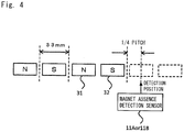
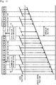
- Fig. 4 is a diagram showing the position in which a magnet absence detection sensor detects an irregular section.
- the pitch of one magnet 3 (a magnet 31 with a north pole and a magnet 32 with a south pole) in the moving direction of the vehicle 1 is 33 mm.
- the magnet absence detection sensor 11A or 11B enters an area having no magnet 3 and then comes to a position corresponding to at least 1/4 of the pitch of a magnet 3, the magnet absence detection sensor detects that it has just entered an irregular section.
- the phase of the magnetic pole is 360° (2n) in the pitch of a set of a magnet 31 with a north pole and a magnet 32 with a south pole (the pitch of two magnets 3)
- the magnetic pole and the electrical angle of the motor 10A or 10B are 90°( ⁇ /2) phase-shifted
- the horizontal thrust becomes cos 90°
- the vertical force becomes sin 90°. That is, the thrust is lost, whereas the large vertical force works.
- the motor 10A or 10B and magnets 3 may adsorb each other, or the vehicle 1 may jump.
- the magnets 3 may be demagnetized.
- the drive of the motor 10A or 10B is stopped.
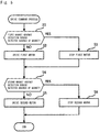
- steps S1 to S3 are performed as follows. Until time t1 in Fig. 6 , the controller 13 determines that the first magnet absence detection sensor 11A has yet to detect the absence of a magnet, since the level of the detection signal from the first magnet absence detection sensor 11A is low. During this period of time, the controller 13 outputs, to the first drive controller 14A, a drive command instructing the first drive controller 14A to drive the first motor 10A. As shown in Fig. 6 , the drive command instructing the first drive controller 14A to drive the first motor 10A is a high-level signal. At time t1 in Fig. 6 , the level of the detection signal from the first magnet absence detection sensor 11A is changed from the low level to a high level.
- the controller 13 determines that the first magnet absence detection sensor 11A has detected the absence of a magnet.
- the controller 13 then outputs, to the first drive controller 14A, a drive command instructing the first drive controller 14A to stop the drive of the first motor 10A.
- the drive signal instructing the first drive controller 14A to stop the first motor 10A is a low-level signal.
- the time period from time t1 to time t2 in Fig. 6 is the time lag between the time point when the controller 13 determines that the level of the detection signal has changed to the high level and the time point when the controller 13 changes the level of the drive command to a low level. If there is a distance between the first magnet absence detection sensor 11A and first motor 10A, this time period is the time period from the time point when the first magnet absence detection sensor 11A enters an irregular section to the time point when the first motor 10A enters the irregular section.
- the detection signal from the first magnet absence detection sensor 11A changes from the high level to a low level.
- the controller 13 determines that the first magnet absence detection sensor 11A no longer detects the absence of a magnet.
- the controller 13 then outputs, to the first drive controller 14A, a drive command instructing the first drive controller 14A to drive the first motor 10A.
- the time period from time t4 to time t5 in Fig. 6 is the time lag between the time point when the controller 13 determines that the detection signal has changed to a low-level signal and the time point when the controller 13 changes the level of the drive command to a high level.
- this time period is the time period from the time point when the magnet absence detection sensor 11A or 11B exits an irregular section to the time point when the motor 10A or 10B exits the irregular section.
- the first drive controller 14A controls the status of the first motor 10A from the stop status to a drive status on the basis of the drive command from the controller 13.
- the time period from time t5 to time t6 in Fig. 6 is the time lag between the time point when the first drive controller 14A determines that the level of the drive command has changed to a high level and the time point when the first drive controller 14A actually drives the first motor 10A.
- the controller 13 always checks the detection signal from the second magnet absence detection sensor 11B (step S4). If the second magnet absence detection sensor 11B has yet to detect the absence of a magnet (NO in step S4), the controller 13 continuously drives the second motor 10B (step S5). Specifically, the controller 13 continuously outputs, to the second drive controller 14B, a drive command instructing the second drive controller 14B to drive the second motor 10B.
- step S5 the controller 13 stops the drive of the second motor 10B (step S5). Specifically, the controller 13 outputs, to the second drive controller 14B, a drive command instructing the second drive controller 14B to stop the drive of the second motor 10B.
- steps S4 to S6 are performed as follows. Until time t7 in Fig. 6 , the controller 13 determines that the second magnet absence detection sensor 11B has yet to detect the absence of a magnet, since the level of the detection signal from the second magnet absence detection sensor 11B is low. During this time period, the controller 13 outputs, to the second drive controller 14B, a drive command instructing the second drive controller 14B to drive the second motor 10B. At time t7 in Fig. 6 , the level of the detection signal from the second magnet absence detection sensor 11B changes from the low level to a high level. Thus, the controller 13 determines that the second magnet absence detection sensor 11B has detected the absence of a magnet.
- the controller 13 then outputs, to the second drive controller 14B, a drive command instructing the second drive controller 14B to stop the drive of the second motor 10B.
- the time period from time t7 to time t8 in Fig. 6 is the time lag between the time point when the controller 13 determines that the level of the detection signal has changed to the high level and the time point when the controller 13 changes the level of the drive command to a low level. If there is a distance between the second magnet absence detection sensor 11B and second motor 10B, this time period is the time period from the time point when the second magnet absence detection sensor 11B enters an irregular section to the time point when the second motor 10B enters the irregular section.
- the second drive controller 14B controls the status of the second motor 10B from the drive status to a stop status on the basis of the drive command from the controller 13. As shown in Fig. 6 , when the second motor 10B is being driven, the level of the drive command is high; when the second motor 10B is being stopped, the level thereof is low.
- the time period from time t8 to time t9 in Fig. 6 is the time lag between the time point when the second drive controller 14B determines that the level of the drive command has changed to the low level and the time point when the second drive controller 14B actually stops the second motor 10B.
- the level of the detection signal from the second magnet absence detection sensor 11B changes from the high level to a low level.
- the controller 13 determines that the second magnet absence detection sensor 11B no longer detects the absence of a magnet.
- the controller 13 then outputs, to the second drive controller 14B, a drive command instructing the second drive controller 14B to drive the second motor 10B.
- the time period from time t10 to time t11 in Fig. 6 is the time lag between the time point when the controller 13 determines that the level of the detection signal has changed to the low level and the time point when the controller 13 changes the level of the drive command to a high level. If there is a distance between the second magnet absence detection sensor 11B and second motor 10B, this time period is the time period from the time point when the second magnet absence detection sensor 11B exits an irregular section to the time point when the second motor 10B exits the irregular section.
- the second drive controller 14B controls the status of the second motor 10B from the stop status to a drive status on the basis of the drive command from the controller 13.
- the time period from time t11 to time t12 in Fig. 6 is the time lag between the time point when the second drive controller 14B determines that the level of the drive command has changed to the high level and the time point when the second drive controller 14B actually drives the second motor 10B.
- the stopped motor cannot be started quickly.
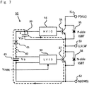
- the motor 10A or 10B is located in an irregular section, the output of the inverter 145A or 145B is stopped to stop the drive of the motor 10A or 10B; and subsequently, when the motor 10A or 10B exits the irregular section, the output of the inverter 145A or 145B is started to drive the motor 10A or 10B (see Fig. 6 ). Accordingly, in the present embodiment, the stopped motor must be started quickly.
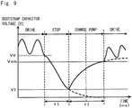
- the charge voltage VDB of the bootstrap capacitor 60 gradually increases.
- the HVIC 56 drives and turns on the IGBT 54.
- the amount of charge of the bootstrap capacitor 60 is used to drive the UGBT 54, so that the charge voltage VDB gradually decreases.
- the charge voltage VDB of the bootstrap capacitor 60 gradually decreases. Subsequently, the IGBT 57 is turned on before the motor is placed in a drive status. Thus, the charge voltage VDB of the bootstrap capacitor 60 gradually increases. At the time point when the charge voltage VDB becomes the voltage value Vmin, the drive of the inverter 145A or 145B is started, and the motor is placed in a drive status.
- Fig. 11 is a diagram showing supplementary position detection control using the second position detection sensor performed when the first position detection sensor is located in an irregular section.
- the controller 13 determines the current position of the vehicle 1 on the basis of the detection signal from the first position detection sensor 12A (step S11).
- Irregular sections include a section in which no magnet 3 is disposed. Accordingly, the vehicle 1 can be driven normally even in a section in which no magnet 3 is disposed on the rail 2. Irregular sections also include a section in which magnets with south poles and magnets with north poles are not alternately disposed. Accordingly, the vehicle 1 can be driven normally even in a section in which magnets 3 are not regularly alternately disposed on the rail 2. Further, the vehicle 1 includes the drive controller 14, which stops the drive of the motor 10A or 10B located in an irregular section. Thus, it is possible to prevent the motor 10A or 10B and the poles of magnets 3 from losing synchronization in an irregular section, as well as to synchronize the motor 10A or 10B and the poles of magnets 3 after the irregular section ends.
- While the two motors are provided with the vehicle 1 in the above embodiment, three or more motors may be provided. Even in this case, when one of the multiple motors is located in an irregular section, the motors other than the one motor are not located in the irregular section. In this case also, a magnet absence detection sensor and a position detection sensor are preferably provided for each of the motors.
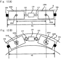
- the position detection sensors While the two position detection sensors, 12A and 12B, are mounted on the vehicle 1 (bogie trucks 100A and 100B) in the example shown in Fig. 12 , the position detection sensors may be mounted on positions other than such positions. Further, another position detection sensor may be mounted on the intermediate part 110. By using the detection sensor mounted on the intermediate part 110, the position of the vehicle 1 (the central position of the vehicle 1) can be detected more precisely.
Landscapes
- Engineering & Computer Science (AREA)
- Power Engineering (AREA)
- Physics & Mathematics (AREA)
- Electromagnetism (AREA)
- Chemical & Material Sciences (AREA)
- Combustion & Propulsion (AREA)
- Transportation (AREA)
- Mechanical Engineering (AREA)
- Microelectronics & Electronic Packaging (AREA)
- General Physics & Mathematics (AREA)
- Control Of Linear Motors (AREA)
- Control Of Vehicles With Linear Motors And Vehicles That Are Magnetically Levitated (AREA)
- Non-Mechanical Conveyors (AREA)
- Control Of Position, Course, Altitude, Or Attitude Of Moving Bodies (AREA)
Applications Claiming Priority (2)
| Application Number | Priority Date | Filing Date | Title |
|---|---|---|---|
| JP2013089409A JP6314372B2 (ja) | 2013-04-22 | 2013-04-22 | 位置検出装置、位置検出方法、及び移動体システム |
| PCT/JP2014/059844 WO2014175033A1 (ja) | 2013-04-22 | 2014-04-03 | 位置検出装置、位置検出方法、及び移動体システム |
Publications (3)
| Publication Number | Publication Date |
|---|---|
| EP2990258A1 EP2990258A1 (en) | 2016-03-02 |
| EP2990258A4 EP2990258A4 (en) | 2016-12-14 |
| EP2990258B1 true EP2990258B1 (en) | 2018-11-28 |
Family
ID=51791614
Family Applications (1)
| Application Number | Title | Priority Date | Filing Date |
|---|---|---|---|
| EP14787645.2A Active EP2990258B1 (en) | 2013-04-22 | 2014-04-03 | Position detection device, position detection method and moving body system |
Country Status (9)
Families Citing this family (15)
| Publication number | Priority date | Publication date | Assignee | Title |
|---|---|---|---|---|
| SG11201801002VA (en) * | 2015-08-21 | 2018-03-28 | Murata Machinery Ltd | Mobile body |
| JP6191665B2 (ja) | 2015-08-21 | 2017-09-06 | 村田機械株式会社 | 移動体 |
| JP6225961B2 (ja) | 2015-08-21 | 2017-11-08 | 村田機械株式会社 | 移動体 |
| JP6206458B2 (ja) | 2015-08-21 | 2017-10-04 | 村田機械株式会社 | 移動体、及び、移動体の位置検出方法 |
| KR102146023B1 (ko) * | 2016-01-07 | 2020-08-19 | 엘지이노텍 주식회사 | 모터 및 이를 포함하는 전동식 조향장치 |
| DE102016203854A1 (de) * | 2016-03-09 | 2017-09-14 | Festo Ag & Co. Kg | Fördereinrichtung |
| JP6840984B2 (ja) | 2016-10-20 | 2021-03-10 | 村田機械株式会社 | リニアモータシステム、移動体システム、及び電気角の推定方法 |
| CN106643644B (zh) * | 2016-11-14 | 2020-02-07 | 西安建筑科技大学 | 一种基于psd的隧道运营期有轨自动监测装置及其监测方法 |
| TWI620916B (zh) * | 2016-11-17 | 2018-04-11 | Absolute position sensing read head device | |
| TWI611165B (zh) * | 2016-12-21 | 2018-01-11 | 國家中山科學研究院 | 積木式電位計 |
| US10304599B2 (en) | 2017-06-22 | 2019-05-28 | National Chung Shan Institute Of Science And Technology | Modular potentiometer |
| US10889449B2 (en) * | 2017-09-25 | 2021-01-12 | Canon Kabushiki Kaisha | Transport system and manufacturing method of article |
| JP7020258B2 (ja) * | 2018-04-06 | 2022-02-16 | 村田機械株式会社 | 位置検出システムおよび走行システム |
| JP2020533781A (ja) * | 2018-06-26 | 2020-11-19 | アプライド マテリアルズ インコーポレイテッドApplied Materials,Incorporated | 強磁性素子までの距離を測定するための距離センサ、磁気浮揚システム、及び強磁性素子までの距離を測定するための方法 |
| DE102023206595A1 (de) * | 2023-07-11 | 2025-01-16 | Swoboda Schorndorf KG | Sensoranordnung für einen Fahrzeugsitz, Fahrzeugsitz sowie Fahrzeug mit demselben |
Family Cites Families (22)
| Publication number | Priority date | Publication date | Assignee | Title |
|---|---|---|---|---|
| JPH0810962B2 (ja) * | 1984-06-29 | 1996-01-31 | 株式会社日立製作所 | リニアモ−タカ−の走行装置 |
| JPH0630522B2 (ja) * | 1985-11-21 | 1994-04-20 | 神鋼電機株式会社 | リニアモ−タ式搬送装置 |
| JPH07112321B2 (ja) * | 1986-07-15 | 1995-11-29 | 財団法人鉄道総合技術研究所 | 位置検出装置 |
| JPH07120194B2 (ja) | 1988-03-31 | 1995-12-20 | 株式会社椿本チエイン | 無人搬送車の走行制御方法及びその装置 |
| JP2958988B2 (ja) * | 1989-09-22 | 1999-10-06 | 日本鋼管株式会社 | カプセル再起動方法 |
| FR2657201B1 (fr) * | 1990-01-12 | 1995-05-24 | Otis Elevator Co | Moteur d'entrainement lineaire a aimants permanents et ses applications. |
| US5023495A (en) * | 1990-04-17 | 1991-06-11 | Hitachi Metals & Shicoh Engine | Moving-magnet type linear d.c. brushless motor having plural moving elements |
| JPH04198713A (ja) * | 1990-11-28 | 1992-07-20 | Furukawa Electric Co Ltd:The | 磁気浮上走行体の位置検出方法 |
| JPH06217592A (ja) * | 1993-01-14 | 1994-08-05 | Hitachi Ltd | リニアシンクロナスモータ式車両の定点停止方法 |
| JP3235708B2 (ja) * | 1995-09-28 | 2001-12-04 | 株式会社ダイフク | リニアモータ利用の搬送設備 |
| JP3436070B2 (ja) * | 1997-05-15 | 2003-08-11 | 株式会社ダイフク | 搬送設備 |
| JP3349137B2 (ja) * | 1999-10-13 | 2002-11-20 | 東海旅客鉄道株式会社 | 車両推進装置 |
| JP4239382B2 (ja) * | 2000-08-24 | 2009-03-18 | 株式会社Ihi | 搬送装置 |
| JP4506319B2 (ja) | 2004-07-15 | 2010-07-21 | ムラテックオートメーション株式会社 | リニアモータ式搬送装置 |
| JP4214533B2 (ja) * | 2006-08-10 | 2009-01-28 | 村田機械株式会社 | 移動体システム |
| WO2008095595A2 (de) | 2007-02-07 | 2008-08-14 | Sew-Eurodrive Gmbh & Co. Kg | Verfahren und system zum ermitteln der position eines motorteils |
| US7804210B2 (en) * | 2008-03-25 | 2010-09-28 | Bose Corporation | Position measurement using magnetic fields |
| JP4438882B2 (ja) * | 2008-05-12 | 2010-03-24 | 村田機械株式会社 | 移動体システム |
| JP4941790B2 (ja) * | 2009-08-28 | 2012-05-30 | 村田機械株式会社 | 移動体システム |
| JP5421709B2 (ja) * | 2009-09-30 | 2014-02-19 | Thk株式会社 | リニアモータの駆動システム及び制御方法 |
| JP5379748B2 (ja) * | 2010-06-03 | 2013-12-25 | Ntn株式会社 | 磁気エンコーダ |
| WO2012056842A1 (ja) * | 2010-10-26 | 2012-05-03 | 村田機械株式会社 | 離散配置リニアモータシステム |
-
2013
- 2013-04-22 JP JP2013089409A patent/JP6314372B2/ja active Active
-
2014
- 2014-04-03 US US14/785,839 patent/US9871434B2/en active Active
- 2014-04-03 EP EP14787645.2A patent/EP2990258B1/en active Active
- 2014-04-03 KR KR1020157030313A patent/KR101870218B1/ko active Active
- 2014-04-03 SG SG11201508624QA patent/SG11201508624QA/en unknown
- 2014-04-03 WO PCT/JP2014/059844 patent/WO2014175033A1/ja active Application Filing
- 2014-04-03 CN CN201480022153.4A patent/CN105142969B/zh active Active
- 2014-04-16 TW TW103113856A patent/TWI646309B/zh active
-
2015
- 2015-10-20 IL IL242190A patent/IL242190B/en active IP Right Grant
Non-Patent Citations (1)
| Title |
|---|
| None * |
Also Published As
| Publication number | Publication date |
|---|---|
| WO2014175033A1 (ja) | 2014-10-30 |
| EP2990258A1 (en) | 2016-03-02 |
| US9871434B2 (en) | 2018-01-16 |
| TWI646309B (zh) | 2019-01-01 |
| SG11201508624QA (en) | 2015-11-27 |
| TW201447237A (zh) | 2014-12-16 |
| JP6314372B2 (ja) | 2018-04-25 |
| KR20150132876A (ko) | 2015-11-26 |
| EP2990258A4 (en) | 2016-12-14 |
| CN105142969A (zh) | 2015-12-09 |
| CN105142969B (zh) | 2018-01-09 |
| JP2014217077A (ja) | 2014-11-17 |
| US20160072367A1 (en) | 2016-03-10 |
| IL242190B (en) | 2019-05-30 |
| KR101870218B1 (ko) | 2018-06-22 |
Similar Documents
| Publication | Publication Date | Title |
|---|---|---|
| EP2990258B1 (en) | Position detection device, position detection method and moving body system | |
| EP2990259B1 (en) | Moving body system and drive method of moving body | |
| JP4941790B2 (ja) | 移動体システム | |
| US6462495B1 (en) | Controlling a brushless DC motor | |
| US11027615B2 (en) | System and method for improving travel across joints in a track for a linear motion system | |
| US9391551B2 (en) | Apparatus to detect the zero-cross of the BEMF of a three-phase electric motor and related method | |
| US12275619B2 (en) | Position-determining system and method for ascertaining a car position of an elevator car | |
| CN102906990B (zh) | 确定电子换向电机的相电流过零、尤其是确定电机转子位置的方法及设备 | |
| US20170054397A1 (en) | Mobile body, mobile body system, and position detecting method for mobile body | |
| US8461826B2 (en) | Device for the detection quadrature signals | |
| CN114450885A (zh) | 交流旋转电机装置 | |
| US9768721B2 (en) | Mobile body and mobile body system | |
| US9729100B2 (en) | Mobile body and mobile body system | |
| CN115594046A (zh) | 一种电梯用封星装置及其电机绕组参数计算方法 | |
| WO2019155524A1 (ja) | 電力変換装置および異常検出方法 | |
| Pottharst et al. | Drive control and position measurement of RailCab vehicles driven by linear motors |
Legal Events
| Date | Code | Title | Description |
|---|---|---|---|
| PUAI | Public reference made under article 153(3) epc to a published international application that has entered the european phase |
Free format text: ORIGINAL CODE: 0009012 |
|
| 17P | Request for examination filed |
Effective date: 20151016 |
|
| AK | Designated contracting states |
Kind code of ref document: A1 Designated state(s): AL AT BE BG CH CY CZ DE DK EE ES FI FR GB GR HR HU IE IS IT LI LT LU LV MC MK MT NL NO PL PT RO RS SE SI SK SM TR |
|
| AX | Request for extension of the european patent |
Extension state: BA ME |
|
| DAX | Request for extension of the european patent (deleted) | ||
| A4 | Supplementary search report drawn up and despatched |
Effective date: 20161110 |
|
| RIC1 | Information provided on ipc code assigned before grant |
Ipc: B61B 13/06 20060101ALI20161104BHEP Ipc: G01D 5/20 20060101ALI20161104BHEP Ipc: H02K 11/215 20160101ALI20161104BHEP Ipc: B61B 13/08 20060101ALI20161104BHEP Ipc: B60L 13/03 20060101AFI20161104BHEP Ipc: H02K 41/03 20060101ALI20161104BHEP Ipc: B60L 15/00 20060101ALI20161104BHEP Ipc: B65G 54/02 20060101ALI20161104BHEP |
|
| STAA | Information on the status of an ep patent application or granted ep patent |
Free format text: STATUS: EXAMINATION IS IN PROGRESS |
|
| 17Q | First examination report despatched |
Effective date: 20171124 |
|
| REG | Reference to a national code |
Ref country code: DE Ref legal event code: R079 Ref document number: 602014037033 Country of ref document: DE Free format text: PREVIOUS MAIN CLASS: B60L0013030000 Ipc: G01D0005140000 |
|
| RIC1 | Information provided on ipc code assigned before grant |
Ipc: G01D 5/14 20060101AFI20180503BHEP Ipc: H02K 41/03 20060101ALI20180503BHEP Ipc: B60L 13/03 20060101ALI20180503BHEP Ipc: G01D 5/20 20060101ALI20180503BHEP Ipc: H02K 11/215 20160101ALI20180503BHEP Ipc: B60L 15/00 20060101ALI20180503BHEP |
|
| GRAP | Despatch of communication of intention to grant a patent |
Free format text: ORIGINAL CODE: EPIDOSNIGR1 |
|
| STAA | Information on the status of an ep patent application or granted ep patent |
Free format text: STATUS: GRANT OF PATENT IS INTENDED |
|
| INTG | Intention to grant announced |
Effective date: 20180627 |
|
| RIN1 | Information on inventor provided before grant (corrected) |
Inventor name: YAMADA, YASUTAKE Inventor name: AZUMA, YOSHIYUKI |
|
| GRAJ | Information related to disapproval of communication of intention to grant by the applicant or resumption of examination proceedings by the epo deleted |
Free format text: ORIGINAL CODE: EPIDOSDIGR1 |
|
| STAA | Information on the status of an ep patent application or granted ep patent |
Free format text: STATUS: EXAMINATION IS IN PROGRESS |
|
| INTC | Intention to grant announced (deleted) | ||
| GRAP | Despatch of communication of intention to grant a patent |
Free format text: ORIGINAL CODE: EPIDOSNIGR1 |
|
| STAA | Information on the status of an ep patent application or granted ep patent |
Free format text: STATUS: GRANT OF PATENT IS INTENDED |
|
| GRAS | Grant fee paid |
Free format text: ORIGINAL CODE: EPIDOSNIGR3 |
|
| GRAA | (expected) grant |
Free format text: ORIGINAL CODE: 0009210 |
|
| STAA | Information on the status of an ep patent application or granted ep patent |
Free format text: STATUS: THE PATENT HAS BEEN GRANTED |
|
| INTG | Intention to grant announced |
Effective date: 20181005 |
|
| AK | Designated contracting states |
Kind code of ref document: B1 Designated state(s): AL AT BE BG CH CY CZ DE DK EE ES FI FR GB GR HR HU IE IS IT LI LT LU LV MC MK MT NL NO PL PT RO RS SE SI SK SM TR |
|
| REG | Reference to a national code |
Ref country code: CH Ref legal event code: EP |
|
| REG | Reference to a national code |
Ref country code: AT Ref legal event code: REF Ref document number: 1070753 Country of ref document: AT Kind code of ref document: T Effective date: 20181215 |
|
| REG | Reference to a national code |
Ref country code: DE Ref legal event code: R096 Ref document number: 602014037033 Country of ref document: DE |
|
| REG | Reference to a national code |
Ref country code: IE Ref legal event code: FG4D |
|
| REG | Reference to a national code |
Ref country code: NL Ref legal event code: MP Effective date: 20181128 |
|
| REG | Reference to a national code |
Ref country code: LT Ref legal event code: MG4D |
|
| REG | Reference to a national code |
Ref country code: AT Ref legal event code: MK05 Ref document number: 1070753 Country of ref document: AT Kind code of ref document: T Effective date: 20181128 |
|
| PG25 | Lapsed in a contracting state [announced via postgrant information from national office to epo] |
Ref country code: BG Free format text: LAPSE BECAUSE OF FAILURE TO SUBMIT A TRANSLATION OF THE DESCRIPTION OR TO PAY THE FEE WITHIN THE PRESCRIBED TIME-LIMIT Effective date: 20190228 Ref country code: HR Free format text: LAPSE BECAUSE OF FAILURE TO SUBMIT A TRANSLATION OF THE DESCRIPTION OR TO PAY THE FEE WITHIN THE PRESCRIBED TIME-LIMIT Effective date: 20181128 Ref country code: LV Free format text: LAPSE BECAUSE OF FAILURE TO SUBMIT A TRANSLATION OF THE DESCRIPTION OR TO PAY THE FEE WITHIN THE PRESCRIBED TIME-LIMIT Effective date: 20181128 Ref country code: FI Free format text: LAPSE BECAUSE OF FAILURE TO SUBMIT A TRANSLATION OF THE DESCRIPTION OR TO PAY THE FEE WITHIN THE PRESCRIBED TIME-LIMIT Effective date: 20181128 Ref country code: ES Free format text: LAPSE BECAUSE OF FAILURE TO SUBMIT A TRANSLATION OF THE DESCRIPTION OR TO PAY THE FEE WITHIN THE PRESCRIBED TIME-LIMIT Effective date: 20181128 Ref country code: AT Free format text: LAPSE BECAUSE OF FAILURE TO SUBMIT A TRANSLATION OF THE DESCRIPTION OR TO PAY THE FEE WITHIN THE PRESCRIBED TIME-LIMIT Effective date: 20181128 Ref country code: LT Free format text: LAPSE BECAUSE OF FAILURE TO SUBMIT A TRANSLATION OF THE DESCRIPTION OR TO PAY THE FEE WITHIN THE PRESCRIBED TIME-LIMIT Effective date: 20181128 Ref country code: IS Free format text: LAPSE BECAUSE OF FAILURE TO SUBMIT A TRANSLATION OF THE DESCRIPTION OR TO PAY THE FEE WITHIN THE PRESCRIBED TIME-LIMIT Effective date: 20190328 Ref country code: NO Free format text: LAPSE BECAUSE OF FAILURE TO SUBMIT A TRANSLATION OF THE DESCRIPTION OR TO PAY THE FEE WITHIN THE PRESCRIBED TIME-LIMIT Effective date: 20190228 |
|
| PG25 | Lapsed in a contracting state [announced via postgrant information from national office to epo] |
Ref country code: GR Free format text: LAPSE BECAUSE OF FAILURE TO SUBMIT A TRANSLATION OF THE DESCRIPTION OR TO PAY THE FEE WITHIN THE PRESCRIBED TIME-LIMIT Effective date: 20190301 Ref country code: PT Free format text: LAPSE BECAUSE OF FAILURE TO SUBMIT A TRANSLATION OF THE DESCRIPTION OR TO PAY THE FEE WITHIN THE PRESCRIBED TIME-LIMIT Effective date: 20190328 Ref country code: SE Free format text: LAPSE BECAUSE OF FAILURE TO SUBMIT A TRANSLATION OF THE DESCRIPTION OR TO PAY THE FEE WITHIN THE PRESCRIBED TIME-LIMIT Effective date: 20181128 Ref country code: RS Free format text: LAPSE BECAUSE OF FAILURE TO SUBMIT A TRANSLATION OF THE DESCRIPTION OR TO PAY THE FEE WITHIN THE PRESCRIBED TIME-LIMIT Effective date: 20181128 Ref country code: AL Free format text: LAPSE BECAUSE OF FAILURE TO SUBMIT A TRANSLATION OF THE DESCRIPTION OR TO PAY THE FEE WITHIN THE PRESCRIBED TIME-LIMIT Effective date: 20181128 |
|
| PG25 | Lapsed in a contracting state [announced via postgrant information from national office to epo] |
Ref country code: NL Free format text: LAPSE BECAUSE OF FAILURE TO SUBMIT A TRANSLATION OF THE DESCRIPTION OR TO PAY THE FEE WITHIN THE PRESCRIBED TIME-LIMIT Effective date: 20181128 |
|
| PG25 | Lapsed in a contracting state [announced via postgrant information from national office to epo] |
Ref country code: PL Free format text: LAPSE BECAUSE OF FAILURE TO SUBMIT A TRANSLATION OF THE DESCRIPTION OR TO PAY THE FEE WITHIN THE PRESCRIBED TIME-LIMIT Effective date: 20181128 Ref country code: IT Free format text: LAPSE BECAUSE OF FAILURE TO SUBMIT A TRANSLATION OF THE DESCRIPTION OR TO PAY THE FEE WITHIN THE PRESCRIBED TIME-LIMIT Effective date: 20181128 Ref country code: CZ Free format text: LAPSE BECAUSE OF FAILURE TO SUBMIT A TRANSLATION OF THE DESCRIPTION OR TO PAY THE FEE WITHIN THE PRESCRIBED TIME-LIMIT Effective date: 20181128 Ref country code: DK Free format text: LAPSE BECAUSE OF FAILURE TO SUBMIT A TRANSLATION OF THE DESCRIPTION OR TO PAY THE FEE WITHIN THE PRESCRIBED TIME-LIMIT Effective date: 20181128 |
|
| REG | Reference to a national code |
Ref country code: DE Ref legal event code: R097 Ref document number: 602014037033 Country of ref document: DE |
|
| PG25 | Lapsed in a contracting state [announced via postgrant information from national office to epo] |
Ref country code: RO Free format text: LAPSE BECAUSE OF FAILURE TO SUBMIT A TRANSLATION OF THE DESCRIPTION OR TO PAY THE FEE WITHIN THE PRESCRIBED TIME-LIMIT Effective date: 20181128 Ref country code: SK Free format text: LAPSE BECAUSE OF FAILURE TO SUBMIT A TRANSLATION OF THE DESCRIPTION OR TO PAY THE FEE WITHIN THE PRESCRIBED TIME-LIMIT Effective date: 20181128 Ref country code: SM Free format text: LAPSE BECAUSE OF FAILURE TO SUBMIT A TRANSLATION OF THE DESCRIPTION OR TO PAY THE FEE WITHIN THE PRESCRIBED TIME-LIMIT Effective date: 20181128 Ref country code: EE Free format text: LAPSE BECAUSE OF FAILURE TO SUBMIT A TRANSLATION OF THE DESCRIPTION OR TO PAY THE FEE WITHIN THE PRESCRIBED TIME-LIMIT Effective date: 20181128 |
|
| PLBE | No opposition filed within time limit |
Free format text: ORIGINAL CODE: 0009261 |
|
| STAA | Information on the status of an ep patent application or granted ep patent |
Free format text: STATUS: NO OPPOSITION FILED WITHIN TIME LIMIT |
|
| PG25 | Lapsed in a contracting state [announced via postgrant information from national office to epo] |
Ref country code: SI Free format text: LAPSE BECAUSE OF FAILURE TO SUBMIT A TRANSLATION OF THE DESCRIPTION OR TO PAY THE FEE WITHIN THE PRESCRIBED TIME-LIMIT Effective date: 20181128 |
|
| 26N | No opposition filed |
Effective date: 20190829 |
|
| REG | Reference to a national code |
Ref country code: CH Ref legal event code: PL |
|
| REG | Reference to a national code |
Ref country code: BE Ref legal event code: MM Effective date: 20190430 |
|
| GBPC | Gb: european patent ceased through non-payment of renewal fee |
Effective date: 20190403 |
|
| PG25 | Lapsed in a contracting state [announced via postgrant information from national office to epo] |
Ref country code: MC Free format text: LAPSE BECAUSE OF FAILURE TO SUBMIT A TRANSLATION OF THE DESCRIPTION OR TO PAY THE FEE WITHIN THE PRESCRIBED TIME-LIMIT Effective date: 20181128 Ref country code: LU Free format text: LAPSE BECAUSE OF NON-PAYMENT OF DUE FEES Effective date: 20190403 |
|
| PG25 | Lapsed in a contracting state [announced via postgrant information from national office to epo] |
Ref country code: GB Free format text: LAPSE BECAUSE OF NON-PAYMENT OF DUE FEES Effective date: 20190403 Ref country code: LI Free format text: LAPSE BECAUSE OF NON-PAYMENT OF DUE FEES Effective date: 20190430 Ref country code: CH Free format text: LAPSE BECAUSE OF NON-PAYMENT OF DUE FEES Effective date: 20190430 |
|
| PG25 | Lapsed in a contracting state [announced via postgrant information from national office to epo] |
Ref country code: FR Free format text: LAPSE BECAUSE OF NON-PAYMENT OF DUE FEES Effective date: 20190430 Ref country code: BE Free format text: LAPSE BECAUSE OF NON-PAYMENT OF DUE FEES Effective date: 20190430 |
|
| PG25 | Lapsed in a contracting state [announced via postgrant information from national office to epo] |
Ref country code: TR Free format text: LAPSE BECAUSE OF FAILURE TO SUBMIT A TRANSLATION OF THE DESCRIPTION OR TO PAY THE FEE WITHIN THE PRESCRIBED TIME-LIMIT Effective date: 20181128 |
|
| PG25 | Lapsed in a contracting state [announced via postgrant information from national office to epo] |
Ref country code: IE Free format text: LAPSE BECAUSE OF NON-PAYMENT OF DUE FEES Effective date: 20190403 |
|
| PG25 | Lapsed in a contracting state [announced via postgrant information from national office to epo] |
Ref country code: CY Free format text: LAPSE BECAUSE OF FAILURE TO SUBMIT A TRANSLATION OF THE DESCRIPTION OR TO PAY THE FEE WITHIN THE PRESCRIBED TIME-LIMIT Effective date: 20181128 |
|
| PG25 | Lapsed in a contracting state [announced via postgrant information from national office to epo] |
Ref country code: MT Free format text: LAPSE BECAUSE OF FAILURE TO SUBMIT A TRANSLATION OF THE DESCRIPTION OR TO PAY THE FEE WITHIN THE PRESCRIBED TIME-LIMIT Effective date: 20181128 Ref country code: HU Free format text: LAPSE BECAUSE OF FAILURE TO SUBMIT A TRANSLATION OF THE DESCRIPTION OR TO PAY THE FEE WITHIN THE PRESCRIBED TIME-LIMIT; INVALID AB INITIO Effective date: 20140403 |
|
| PG25 | Lapsed in a contracting state [announced via postgrant information from national office to epo] |
Ref country code: MK Free format text: LAPSE BECAUSE OF FAILURE TO SUBMIT A TRANSLATION OF THE DESCRIPTION OR TO PAY THE FEE WITHIN THE PRESCRIBED TIME-LIMIT Effective date: 20181128 |
|
| PGFP | Annual fee paid to national office [announced via postgrant information from national office to epo] |
Ref country code: DE Payment date: 20250319 Year of fee payment: 12 |