EP2990258B1 - Position detection device, position detection method and moving body system - Google Patents
Position detection device, position detection method and moving body system Download PDFInfo
- Publication number
- EP2990258B1 EP2990258B1 EP14787645.2A EP14787645A EP2990258B1 EP 2990258 B1 EP2990258 B1 EP 2990258B1 EP 14787645 A EP14787645 A EP 14787645A EP 2990258 B1 EP2990258 B1 EP 2990258B1
- Authority
- EP
- European Patent Office
- Prior art keywords
- motor
- controller
- detection sensor
- drive
- magnet
- Prior art date
- Legal status (The legal status is an assumption and is not a legal conclusion. Google has not performed a legal analysis and makes no representation as to the accuracy of the status listed.)
- Active
Links
Images


Classifications
-
- H—ELECTRICITY
- H02—GENERATION; CONVERSION OR DISTRIBUTION OF ELECTRIC POWER
- H02K—DYNAMO-ELECTRIC MACHINES
- H02K41/00—Propulsion systems in which a rigid body is moved along a path due to dynamo-electric interaction between the body and a magnetic field travelling along the path
- H02K41/02—Linear motors; Sectional motors
- H02K41/03—Synchronous motors; Motors moving step by step; Reluctance motors
- H02K41/031—Synchronous motors; Motors moving step by step; Reluctance motors of the permanent magnet type
-
- B—PERFORMING OPERATIONS; TRANSPORTING
- B60—VEHICLES IN GENERAL
- B60L—PROPULSION OF ELECTRICALLY-PROPELLED VEHICLES; SUPPLYING ELECTRIC POWER FOR AUXILIARY EQUIPMENT OF ELECTRICALLY-PROPELLED VEHICLES; ELECTRODYNAMIC BRAKE SYSTEMS FOR VEHICLES IN GENERAL; MAGNETIC SUSPENSION OR LEVITATION FOR VEHICLES; MONITORING OPERATING VARIABLES OF ELECTRICALLY-PROPELLED VEHICLES; ELECTRIC SAFETY DEVICES FOR ELECTRICALLY-PROPELLED VEHICLES
- B60L15/00—Methods, circuits, or devices for controlling the traction-motor speed of electrically-propelled vehicles
- B60L15/002—Methods, circuits, or devices for controlling the traction-motor speed of electrically-propelled vehicles for control of propulsion for monorail vehicles, suspension vehicles or rack railways; for control of magnetic suspension or levitation for vehicles for propulsion purposes
- B60L15/005—Methods, circuits, or devices for controlling the traction-motor speed of electrically-propelled vehicles for control of propulsion for monorail vehicles, suspension vehicles or rack railways; for control of magnetic suspension or levitation for vehicles for propulsion purposes for control of propulsion for vehicles propelled by linear motors
-
- G—PHYSICS
- G01—MEASURING; TESTING
- G01D—MEASURING NOT SPECIALLY ADAPTED FOR A SPECIFIC VARIABLE; ARRANGEMENTS FOR MEASURING TWO OR MORE VARIABLES NOT COVERED IN A SINGLE OTHER SUBCLASS; TARIFF METERING APPARATUS; MEASURING OR TESTING NOT OTHERWISE PROVIDED FOR
- G01D5/00—Mechanical means for transferring the output of a sensing member; Means for converting the output of a sensing member to another variable where the form or nature of the sensing member does not constrain the means for converting; Transducers not specially adapted for a specific variable
- G01D5/12—Mechanical means for transferring the output of a sensing member; Means for converting the output of a sensing member to another variable where the form or nature of the sensing member does not constrain the means for converting; Transducers not specially adapted for a specific variable using electric or magnetic means
- G01D5/14—Mechanical means for transferring the output of a sensing member; Means for converting the output of a sensing member to another variable where the form or nature of the sensing member does not constrain the means for converting; Transducers not specially adapted for a specific variable using electric or magnetic means influencing the magnitude of a current or voltage
- G01D5/20—Mechanical means for transferring the output of a sensing member; Means for converting the output of a sensing member to another variable where the form or nature of the sensing member does not constrain the means for converting; Transducers not specially adapted for a specific variable using electric or magnetic means influencing the magnitude of a current or voltage by varying inductance, e.g. by a movable armature
-
- H—ELECTRICITY
- H02—GENERATION; CONVERSION OR DISTRIBUTION OF ELECTRIC POWER
- H02K—DYNAMO-ELECTRIC MACHINES
- H02K11/00—Structural association of dynamo-electric machines with electric components or with devices for shielding, monitoring or protection
- H02K11/20—Structural association of dynamo-electric machines with electric components or with devices for shielding, monitoring or protection for measuring, monitoring, testing, protecting or switching
- H02K11/21—Devices for sensing speed or position, or actuated thereby
- H02K11/215—Magnetic effect devices, e.g. Hall-effect or magneto-resistive elements
-
- B—PERFORMING OPERATIONS; TRANSPORTING
- B60—VEHICLES IN GENERAL
- B60L—PROPULSION OF ELECTRICALLY-PROPELLED VEHICLES; SUPPLYING ELECTRIC POWER FOR AUXILIARY EQUIPMENT OF ELECTRICALLY-PROPELLED VEHICLES; ELECTRODYNAMIC BRAKE SYSTEMS FOR VEHICLES IN GENERAL; MAGNETIC SUSPENSION OR LEVITATION FOR VEHICLES; MONITORING OPERATING VARIABLES OF ELECTRICALLY-PROPELLED VEHICLES; ELECTRIC SAFETY DEVICES FOR ELECTRICALLY-PROPELLED VEHICLES
- B60L13/00—Electric propulsion for monorail vehicles, suspension vehicles or rack railways; Magnetic suspension or levitation for vehicles
- B60L13/03—Electric propulsion by linear motors
-
- G—PHYSICS
- G01—MEASURING; TESTING
- G01D—MEASURING NOT SPECIALLY ADAPTED FOR A SPECIFIC VARIABLE; ARRANGEMENTS FOR MEASURING TWO OR MORE VARIABLES NOT COVERED IN A SINGLE OTHER SUBCLASS; TARIFF METERING APPARATUS; MEASURING OR TESTING NOT OTHERWISE PROVIDED FOR
- G01D5/00—Mechanical means for transferring the output of a sensing member; Means for converting the output of a sensing member to another variable where the form or nature of the sensing member does not constrain the means for converting; Transducers not specially adapted for a specific variable
- G01D5/12—Mechanical means for transferring the output of a sensing member; Means for converting the output of a sensing member to another variable where the form or nature of the sensing member does not constrain the means for converting; Transducers not specially adapted for a specific variable using electric or magnetic means
- G01D5/14—Mechanical means for transferring the output of a sensing member; Means for converting the output of a sensing member to another variable where the form or nature of the sensing member does not constrain the means for converting; Transducers not specially adapted for a specific variable using electric or magnetic means influencing the magnitude of a current or voltage
- G01D5/142—Mechanical means for transferring the output of a sensing member; Means for converting the output of a sensing member to another variable where the form or nature of the sensing member does not constrain the means for converting; Transducers not specially adapted for a specific variable using electric or magnetic means influencing the magnitude of a current or voltage using Hall-effect devices
- G01D5/145—Mechanical means for transferring the output of a sensing member; Means for converting the output of a sensing member to another variable where the form or nature of the sensing member does not constrain the means for converting; Transducers not specially adapted for a specific variable using electric or magnetic means influencing the magnitude of a current or voltage using Hall-effect devices influenced by the relative movement between the Hall device and magnetic fields
-
- Y—GENERAL TAGGING OF NEW TECHNOLOGICAL DEVELOPMENTS; GENERAL TAGGING OF CROSS-SECTIONAL TECHNOLOGIES SPANNING OVER SEVERAL SECTIONS OF THE IPC; TECHNICAL SUBJECTS COVERED BY FORMER USPC CROSS-REFERENCE ART COLLECTIONS [XRACs] AND DIGESTS
- Y02—TECHNOLOGIES OR APPLICATIONS FOR MITIGATION OR ADAPTATION AGAINST CLIMATE CHANGE
- Y02T—CLIMATE CHANGE MITIGATION TECHNOLOGIES RELATED TO TRANSPORTATION
- Y02T10/00—Road transport of goods or passengers
- Y02T10/60—Other road transportation technologies with climate change mitigation effect
- Y02T10/64—Electric machine technologies in electromobility
Definitions
- the present invention relates to a position detection device for detecting the position of a moving body moving on a movement path, a position detection method, and a moving body system.
- the moving body systems using linear motors are those using secondary-side-on-ground type linear motors.
- the secondary-side-on-ground type is a type in which linear motors are mounted on a mover (moving body) and magnets are disposed on a stator (rail).
- a moving body system of this type for example, there is known a moving body system in which magnets with south poles and magnets with north poles are alternately disposed on a rail (movement path) and a moving body having linear motors mounted thereon moves along the rail, as disclosed in Patent Literature 1.
- the moving body includes a position detector that detects the poles of magnets. The continuous positions of the moving body are determined based on detection results obtained by the position detector.
- Patent Literature 1 Japanese Unexamined Patent Application Publication No. 2006-27421
- the second position detector may detect the position of the moving body by detecting the poles of the magnets.
- the controller may determine that one of the first position detector and second position detector is located in the irregular section, by comparing a position detected by the first position detector and the position detected by the second position detector.
- the controller may determine a moving distance of the moving body in the irregular section on the basis of the position detected by the second position detector and may determine the position of the moving body on the basis of the determined moving distance.
- the irregular section may be a section in which the magnets are not disposed.
- the irregular section may also be a section in which the magnets with south poles and magnets with north poles are not alternately disposed.
- the irregular section may be shorter than a distance between the first position detector and second position detector in the moving direction.
- the present invention also provides a moving body system including a movement path on which magnets with south poles and magnets with north poles are alternately disposed and a moving body capable of moving along the movement path.
- the moving body includes the above position detection device.
- the controller determines the position of the moving body on the basis of the position detected by the second position detector.
- the second position detector detects the position of the moving body by detecting the poles of the magnets.
- the controller determines that one of the first position detector and second position detector is located in the irregular section, by comparing a position detected by the first position detector and the position detected by the second position detector. Thus, it is possible to reliably determine that one of the first position detector and second position detector is located in an irregular section.
- irregular sections include a section in which no magnet is disposed. Thus, it is possible to reliably determine the position of the moving body even in a section in which no magnet is disposed. Further, irregular sections include a section in which magnets with south poles and magnets with north poles are not alternately disposed. Thus, it is possible to reliably determine the position of the moving body even in a section in which magnets with south poles and magnets with north poles are not alternately disposed.
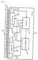
- Fig. 1 is a block diagram showing a moving body system according to the present embodiment.
- the moving body system shown in Fig. 1 is a system using secondary-side-on-ground type linear motors.
- This moving body system includes a vehicle 1 serving as a moving body and a rail 2 serving as the movement path of the moving body. Magnets 3 with north poles and magnets 3 with south poles are alternately disposed in a row with a predetermined pitch on the rail 2.
- the moving body system shown in Fig. 1 is, for example, a ceiling traveling vehicle system in which a vehicle 1 travels along a rail 2 installed on the ceiling. In the present embodiment, it is assumed that the moving body system includes a rail 2 having a length of several km and 300 to 400 vehicles 1.
- the moving body of the present embodiment is not limited to the vehicle 1 and may be any vehicles other than the vehicle 1 or moving bodies such as a robot arm.
- the first motor 10A and second motor 10B are linear motors which change the magnetic field so that the magnets 3 with south poles and magnets 3 with north poles alternately disposed on the rail 2 and the electrical angle thereof are synchronized.
- three-phase (U, V, and W phases) linear synchronous motors are used as the linear motors.
- the first motor 10A and second motor 10B are disposed in different positions in the moving direction of the vehicle 1 (in the direction of the rail 2 shown in Fig. 1 ).
- the first motor 10A and second motor 10B are disposed in positions which are opposed to magnets 3 on the rail 2 in the vehicle 1 and which are adjacent to the magnets 3.
- the first motor 10A is disposed in a front position in the moving direction of the vehicle 1, and the second motor 10B is disposed in a rear position in the moving direction of the vehicle 1.
- the front in the moving direction is referred to as front, and the rear in the moving direction is referred to as rear.
- the first magnet absence detection sensor 11A and second magnet absence detection sensor 11B are detectors which detect the magnets 3 on the rail 2.
- the first magnet absence detection sensor 11A is a detector for detecting that the first motor 10A is located in a section in which no magnet 3 is disposed on the rail 2 (an irregular section shown in Fig. 3 ).
- the second magnet absence detection sensor 11B is a detector for detecting that the second motor 10B is located in a section in which no magnet 3 is disposed on the rail 2 (the irregular section shown in Fig. 3 ).
- the first magnet absence detection sensor 11A and second magnet absence detection sensor 11B include, for example, photosensors that detect objects (the magnets 3 with south poles and magnets 3 with north poles in Fig. 1 ) by receiving light emitted by a light emitter using a light receiver.
- the first magnet absence detection sensor 11A and second magnet absence detection sensor 11B are also disposed in positions which are opposed to magnets 3 on the rail 2 in the vehicle 1 and which are adjacent to the magnets 3.
- the first magnet absence detection sensor 11A and the second magnet absence detection sensor 11B output detection signals to the controller 13.
- the first position detection sensor 12A and the second position detection sensor 12B are position detectors which detect the position of the vehicle 1 on the rail 2.
- the position of the vehicle 1 is determined based on a position detected by the first position detection sensor 12A.
- the position of the vehicle 1 is determined based on a position detected by the second position detection sensor 12B.
- the first position detection sensor 12A and the second position detection sensor 12B include, for example, magnetic pole detection sensors using Hall-effect devices (magnetic conversion devices; hereafter simply referred to as "Hall devices").
- the detection heads of the first position detection sensor 12A and the second position detection sensor 12B are provided with Hall devices. When the detection heads move relatively to the magnets 3 with the movement of the vehicle 1, the direction of the magnetic field with respect to the magnetosensitive surfaces of the Hall devices changes. The Hall devices output electrical signals corresponding to the changed angle. The position of the vehicle 1 on the rail 2 is detected based on the values (voltage values) of the electrical signals.
- the first position detection sensor 12A and the second position detection sensor 12B are also disposed in positions which are opposed to magnets 3 on the rail 2 in the vehicle 1 and which are adjacent to the magnets 3.
- the first position detection sensor 12A and the second position detection sensor 12B output detection signals to the controller 13.
- the controller 13 determines whether the first motor 10A is located in an irregular section, on the basis of the detection signal from the first magnet absence detection sensor 11A. If the controller 13 determines that the first motor 10A is not located in any irregular section, it outputs, to the drive controller 14, a drive command instructing the drive controller 14 to drive the first motor 10A. In contrast, if the controller 13 determines that the first motor 10A is located in an irregular section, it outputs, to the drive controller 14, a drive command instructing the drive controller 14 to stop the drive of the first motor 10A. Similarly, the controller 13 determines whether the second motor 10B is located in an irregular section, on the basis of the detection signal from the second magnet absence detection sensor 11B.
- the controller 13 determines that the second motor 10B is not located in any irregular section, it outputs, to the drive controller 14, a drive command instructing the drive controller 14 to drive the second motor 10B. In contrast, if the controller 13 determines that the second motor 10B is located in an irregular section, it outputs, to the drive controller 14, a drive command instructing the drive controller 14 to stop the drive of the second motor 10B. As shown in Fig. 6 , when the signal level of the drive command is high, the motor 10A or 10B is driven; when the signal level thereof is low, the motor 10A or 10B is stopped.
- the controller 13 determines the position of the vehicle 1 on the basis of the detection signal from the first position detection sensor 12A. In contrast, when the first position detection sensor 12A is located in an irregular section, the controller 13 determines the position of the vehicle 1 on the basis of the detection signal from the second position detection sensor 12B. Then, based on the determined position of the vehicle 1, the controller 13 outputs, to the drive controller 14, a position command instructing the drive controller 14 to move the vehicle 1 to a movement position.
- the drive controller 14 controls the drive or stop of the first motor 10A on the basis of the drive command related to the first motor 10A from the controller 13.
- the drive controller 14 also controls the drive or stop of the second motor 10B on the basis of the drive command related to the second motor 10B from the controller 13.
- the drive controller 14 also controls the drive of the first motor 10A and second motor 10B so that the vehicle 1 moves to the movement position, on the basis of the position command from the controller 13.
- first magnet absence detection sensor 11A and the first position detection sensor 12A are disposed in positions adjacent to the first motor 10A in the example shown in Fig. 1 , these sensors need not necessarily be disposed in such positions.
- second magnet absence detection sensor 11B and the second position detection sensor 12B are disposed in positions adjacent to the second motor 10B, these sensors need not necessarily be disposed in such positions.
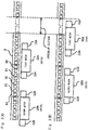
- Fig. 2 is a block diagram showing the internal configurations of the controller and drive controller.
- the controller 13 shown in Fig. 1 includes a position controller 131, a magnetless controller 132, and a motion controller 133.
- the drive controller 14 shown in Fig. 1 includes a first drive controller 14A that controls the drive of the first motor 10A and a second drive controller 14B that controls the drive of the second motor 10B.
- MMD shown in Fig. 2 represents a magnetless detect, that is, the magnet absence detection sensor 11A or 11B.
- PS shown in Fig. 2 represents a position sensor, that is, the position detection sensor 12A or 12B.
- the position controller 131 determines whether the first motor 10A is located in an irregular section, on the basis of the detection signal from the first magnet absence detection sensor 11A. If the position controller 131 determines that the first motor 10A is not located in any irregular section, it outputs a magnet absence detection status signal ("MLD-status" in Fig. 2 ) indicating this status, to the magnetless controller 132 and motion controller 133. The position controller 131 also determines whether the second motor 10B is located in an irregular section, on the basis of the detection signal from the second magnet absence detection sensor 11B. If the position controller 131 determines that the second motor 10B is not located in any irregular section, it outputs a magnet absence detection signal indicating this status, to the magnetless controller 132 and motion controller 133.
- MLD-status magnet absence detection status signal
- the position controller 131 determines the position of the vehicle 1 on the basis of the detection signal from the first position detection sensor 12A. In contrast, when the first position detection sensor 12A is located in an irregular section, the position controller 131 determines the position of the vehicle 1 on the basis of the detection signal from the second position detection sensor 12B. The position controller 131 then outputs position information indicating the determined current position of the vehicle 1 to the motion controller 133, first drive controller 14A, and second drive controller 14B.
- the motion controller 133 determines whether the first motor 10A and second motor 10B are located in an irregular section, on the basis of the magnet absence detection signals from the position controller 131. The motion controller 133 also checks the current position of the vehicle 1 on the basis of the position information from the position controller 131. The motion controller 133 then outputs, to the drive controller 14A or 14B of the motor 10A or 10B which is not located in any irregular section, a position command instructing the drive controller to move the vehicle 1 to a predetermined position (the movement position to which the vehicle 1 is to be moved).
- the length of the rail 2 must be an integral multiple of that of a magnet unit 3U.
- an irregular section in which no magnet 3 is disposed would easily occur on the rail 2. Further, the generated irregular section would have a long length. In the example shown in Fig. 3 , there is generated an irregular section corresponding to about twice the pitch of a magnet.
- both the first magnet absence detection sensor 11A and second magnet absence detection sensor 11B have yet to enter the irregular section. Accordingly, both the first motor 10A and second motor 10B are being driven.
- the second magnet absence detection sensor 11B has yet to enter the irregular section, whereas the first magnet absence detection sensor 11A has entered the irregular section. Accordingly, only the second motor 10B is being driven, and the first motor 10A is not being driven (that is, the drive of the first magnet absence detection sensor 11A is being stopped). Subsequently, when the vehicle 1 moves in the traveling direction, the second magnet absence detection sensor 11B enters the irregular section. In this case, the drive of the second motor 10B is stopped.
- an "irregular section” refers to a section in which the poles of magnets are not disposed regularly, that is, a section in which magnets 31 with north poles and magnets 32 with south poles are not disposed regularly. Accordingly, “irregular sections” include sections in which no magnet 3 is disposed, as well as sections in which magnets 31 with north poles and magnets 32 with south poles are not alternately disposed. “Irregular sections” also include sections in which magnets 3 have weakening magnetic forces. Even in such sections, control is performed such that the motor 10A or 10B is stopped.
- the motor e.g., second motor 10B
- the length of any irregular section is set to a length shorter than that distance.
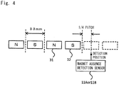
- Fig. 4 is a diagram showing the position in which a magnet absence detection sensor detects an irregular section.
- the pitch of one magnet 3 (a magnet 31 with a north pole and a magnet 32 with a south pole) in the moving direction of the vehicle 1 is 33 mm.
- the magnet absence detection sensor 11A or 11B enters an area having no magnet 3 and then comes to a position corresponding to at least 1/4 of the pitch of a magnet 3, the magnet absence detection sensor detects that it has just entered an irregular section.
- the phase of the magnetic pole is 360° (2n) in the pitch of a set of a magnet 31 with a north pole and a magnet 32 with a south pole (the pitch of two magnets 3)
- the magnetic pole and the electrical angle of the motor 10A or 10B are 90°( ⁇ /2) phase-shifted
- the horizontal thrust becomes cos 90°
- the vertical force becomes sin 90°. That is, the thrust is lost, whereas the large vertical force works.
- the motor 10A or 10B and magnets 3 may adsorb each other, or the vehicle 1 may jump.
- the magnets 3 may be demagnetized.
- the drive of the motor 10A or 10B is stopped.
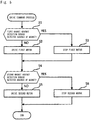
- steps S1 to S3 are performed as follows. Until time t1 in Fig. 6 , the controller 13 determines that the first magnet absence detection sensor 11A has yet to detect the absence of a magnet, since the level of the detection signal from the first magnet absence detection sensor 11A is low. During this period of time, the controller 13 outputs, to the first drive controller 14A, a drive command instructing the first drive controller 14A to drive the first motor 10A. As shown in Fig. 6 , the drive command instructing the first drive controller 14A to drive the first motor 10A is a high-level signal. At time t1 in Fig. 6 , the level of the detection signal from the first magnet absence detection sensor 11A is changed from the low level to a high level.
- the controller 13 determines that the first magnet absence detection sensor 11A has detected the absence of a magnet.
- the controller 13 then outputs, to the first drive controller 14A, a drive command instructing the first drive controller 14A to stop the drive of the first motor 10A.
- the drive signal instructing the first drive controller 14A to stop the first motor 10A is a low-level signal.
- the time period from time t1 to time t2 in Fig. 6 is the time lag between the time point when the controller 13 determines that the level of the detection signal has changed to the high level and the time point when the controller 13 changes the level of the drive command to a low level. If there is a distance between the first magnet absence detection sensor 11A and first motor 10A, this time period is the time period from the time point when the first magnet absence detection sensor 11A enters an irregular section to the time point when the first motor 10A enters the irregular section.
- the detection signal from the first magnet absence detection sensor 11A changes from the high level to a low level.
- the controller 13 determines that the first magnet absence detection sensor 11A no longer detects the absence of a magnet.
- the controller 13 then outputs, to the first drive controller 14A, a drive command instructing the first drive controller 14A to drive the first motor 10A.
- the time period from time t4 to time t5 in Fig. 6 is the time lag between the time point when the controller 13 determines that the detection signal has changed to a low-level signal and the time point when the controller 13 changes the level of the drive command to a high level.
- this time period is the time period from the time point when the magnet absence detection sensor 11A or 11B exits an irregular section to the time point when the motor 10A or 10B exits the irregular section.
- the first drive controller 14A controls the status of the first motor 10A from the stop status to a drive status on the basis of the drive command from the controller 13.
- the time period from time t5 to time t6 in Fig. 6 is the time lag between the time point when the first drive controller 14A determines that the level of the drive command has changed to a high level and the time point when the first drive controller 14A actually drives the first motor 10A.
- the controller 13 always checks the detection signal from the second magnet absence detection sensor 11B (step S4). If the second magnet absence detection sensor 11B has yet to detect the absence of a magnet (NO in step S4), the controller 13 continuously drives the second motor 10B (step S5). Specifically, the controller 13 continuously outputs, to the second drive controller 14B, a drive command instructing the second drive controller 14B to drive the second motor 10B.
- step S5 the controller 13 stops the drive of the second motor 10B (step S5). Specifically, the controller 13 outputs, to the second drive controller 14B, a drive command instructing the second drive controller 14B to stop the drive of the second motor 10B.
- steps S4 to S6 are performed as follows. Until time t7 in Fig. 6 , the controller 13 determines that the second magnet absence detection sensor 11B has yet to detect the absence of a magnet, since the level of the detection signal from the second magnet absence detection sensor 11B is low. During this time period, the controller 13 outputs, to the second drive controller 14B, a drive command instructing the second drive controller 14B to drive the second motor 10B. At time t7 in Fig. 6 , the level of the detection signal from the second magnet absence detection sensor 11B changes from the low level to a high level. Thus, the controller 13 determines that the second magnet absence detection sensor 11B has detected the absence of a magnet.
- the controller 13 then outputs, to the second drive controller 14B, a drive command instructing the second drive controller 14B to stop the drive of the second motor 10B.
- the time period from time t7 to time t8 in Fig. 6 is the time lag between the time point when the controller 13 determines that the level of the detection signal has changed to the high level and the time point when the controller 13 changes the level of the drive command to a low level. If there is a distance between the second magnet absence detection sensor 11B and second motor 10B, this time period is the time period from the time point when the second magnet absence detection sensor 11B enters an irregular section to the time point when the second motor 10B enters the irregular section.
- the second drive controller 14B controls the status of the second motor 10B from the drive status to a stop status on the basis of the drive command from the controller 13. As shown in Fig. 6 , when the second motor 10B is being driven, the level of the drive command is high; when the second motor 10B is being stopped, the level thereof is low.
- the time period from time t8 to time t9 in Fig. 6 is the time lag between the time point when the second drive controller 14B determines that the level of the drive command has changed to the low level and the time point when the second drive controller 14B actually stops the second motor 10B.
- the level of the detection signal from the second magnet absence detection sensor 11B changes from the high level to a low level.
- the controller 13 determines that the second magnet absence detection sensor 11B no longer detects the absence of a magnet.
- the controller 13 then outputs, to the second drive controller 14B, a drive command instructing the second drive controller 14B to drive the second motor 10B.
- the time period from time t10 to time t11 in Fig. 6 is the time lag between the time point when the controller 13 determines that the level of the detection signal has changed to the low level and the time point when the controller 13 changes the level of the drive command to a high level. If there is a distance between the second magnet absence detection sensor 11B and second motor 10B, this time period is the time period from the time point when the second magnet absence detection sensor 11B exits an irregular section to the time point when the second motor 10B exits the irregular section.
- the second drive controller 14B controls the status of the second motor 10B from the stop status to a drive status on the basis of the drive command from the controller 13.
- the time period from time t11 to time t12 in Fig. 6 is the time lag between the time point when the second drive controller 14B determines that the level of the drive command has changed to the high level and the time point when the second drive controller 14B actually drives the second motor 10B.
- the stopped motor cannot be started quickly.
- the motor 10A or 10B is located in an irregular section, the output of the inverter 145A or 145B is stopped to stop the drive of the motor 10A or 10B; and subsequently, when the motor 10A or 10B exits the irregular section, the output of the inverter 145A or 145B is started to drive the motor 10A or 10B (see Fig. 6 ). Accordingly, in the present embodiment, the stopped motor must be started quickly.
- the charge voltage VDB of the bootstrap capacitor 60 gradually increases.
- the HVIC 56 drives and turns on the IGBT 54.
- the amount of charge of the bootstrap capacitor 60 is used to drive the UGBT 54, so that the charge voltage VDB gradually decreases.
- the charge voltage VDB of the bootstrap capacitor 60 gradually decreases. Subsequently, the IGBT 57 is turned on before the motor is placed in a drive status. Thus, the charge voltage VDB of the bootstrap capacitor 60 gradually increases. At the time point when the charge voltage VDB becomes the voltage value Vmin, the drive of the inverter 145A or 145B is started, and the motor is placed in a drive status.
- Fig. 11 is a diagram showing supplementary position detection control using the second position detection sensor performed when the first position detection sensor is located in an irregular section.
- the controller 13 determines the current position of the vehicle 1 on the basis of the detection signal from the first position detection sensor 12A (step S11).
- Irregular sections include a section in which no magnet 3 is disposed. Accordingly, the vehicle 1 can be driven normally even in a section in which no magnet 3 is disposed on the rail 2. Irregular sections also include a section in which magnets with south poles and magnets with north poles are not alternately disposed. Accordingly, the vehicle 1 can be driven normally even in a section in which magnets 3 are not regularly alternately disposed on the rail 2. Further, the vehicle 1 includes the drive controller 14, which stops the drive of the motor 10A or 10B located in an irregular section. Thus, it is possible to prevent the motor 10A or 10B and the poles of magnets 3 from losing synchronization in an irregular section, as well as to synchronize the motor 10A or 10B and the poles of magnets 3 after the irregular section ends.
- While the two motors are provided with the vehicle 1 in the above embodiment, three or more motors may be provided. Even in this case, when one of the multiple motors is located in an irregular section, the motors other than the one motor are not located in the irregular section. In this case also, a magnet absence detection sensor and a position detection sensor are preferably provided for each of the motors.
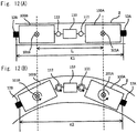
- the position detection sensors While the two position detection sensors, 12A and 12B, are mounted on the vehicle 1 (bogie trucks 100A and 100B) in the example shown in Fig. 12 , the position detection sensors may be mounted on positions other than such positions. Further, another position detection sensor may be mounted on the intermediate part 110. By using the detection sensor mounted on the intermediate part 110, the position of the vehicle 1 (the central position of the vehicle 1) can be detected more precisely.
Description
- The present invention relates to a position detection device for detecting the position of a moving body moving on a movement path, a position detection method, and a moving body system.
- There have been known moving body systems using linear motors. Among such moving body systems are those using secondary-side-on-ground type linear motors. The secondary-side-on-ground type is a type in which linear motors are mounted on a mover (moving body) and magnets are disposed on a stator (rail). As a moving body system of this type, for example, there is known a moving body system in which magnets with south poles and magnets with north poles are alternately disposed on a rail (movement path) and a moving body having linear motors mounted thereon moves along the rail, as disclosed in
Patent Literature 1. The moving body includes a position detector that detects the poles of magnets. The continuous positions of the moving body are determined based on detection results obtained by the position detector. - [Patent Literature 1] Japanese Unexamined Patent Application Publication No.
2006-27421 - When magnets with south poles and magnets with north poles are alternately disposed on a rail, as in the moving body system disclosed in
Patent Literature 1, gaps occur between magnets on the rail, unless the rail length (i.e., the length of the movement path) is an integer multiple of the pitch of a magnet. When gaps occur between magnets on the rail, the position detector included in the moving body cannot detect the positions of magnetic poles in the gaps. Consequently, the moving body cannot obtain accurate and continuous position information. - The present invention has been made in view of the foregoing, and an object thereof is to provide a position detection device that can determine the precise position of a moving body even when any section in which the position cannot be detected is present on the movement path, a position detection method, and a moving body.
- To accomplish the above object, the present invention provides a position detection device according to
claim 1. - The second position detector may detect the position of the moving body by detecting the poles of the magnets. The controller may determine that one of the first position detector and second position detector is located in the irregular section, by comparing a position detected by the first position detector and the position detected by the second position detector. When the first position detector is located in the irregular section, the controller may determine a moving distance of the moving body in the irregular section on the basis of the position detected by the second position detector and may determine the position of the moving body on the basis of the determined moving distance. The irregular section may be a section in which the magnets are not disposed. The irregular section may also be a section in which the magnets with south poles and magnets with north poles are not alternately disposed. The irregular section may be shorter than a distance between the first position detector and second position detector in the moving direction.
- The present invention also provides a method for detecting a position of a moving body according to claim 8.
- The present invention also provides a moving body system including a movement path on which magnets with south poles and magnets with north poles are alternately disposed and a moving body capable of moving along the movement path. The moving body includes the above position detection device.
- According to the present invention, when the first position detector is located in an irregular section in which the poles of the magnets are not disposed regularly, the controller determines the position of the moving body on the basis of the position detected by the second position detector.
- Thus, even when an irregular section in which the position cannot be detected is present on the moving path, it is possible to determine the precise position of the moving body.
- Further, the second position detector detects the position of the moving body by detecting the poles of the magnets. Thus, it is possible to reliably determine the magnet-based position of the moving body. As a result, it is possible to reliably synchronize the motor of the moving body and the positions of the poles of the magnets.
- Further, the controller determines that one of the first position detector and second position detector is located in the irregular section, by comparing a position detected by the first position detector and the position detected by the second position detector. Thus, it is possible to reliably determine that one of the first position detector and second position detector is located in an irregular section.
- Further, irregular sections include a section in which no magnet is disposed. Thus, it is possible to reliably determine the position of the moving body even in a section in which no magnet is disposed. Further, irregular sections include a section in which magnets with south poles and magnets with north poles are not alternately disposed. Thus, it is possible to reliably determine the position of the moving body even in a section in which magnets with south poles and magnets with north poles are not alternately disposed.
-
-
Fig. 1 is a block diagram showing a moving body system according to the present embodiment. -
Fig. 2 is a block diagram showing the internal configurations of a controller and a drive controller. -
Fig. 3 is a diagram showing an irregular section on a rail, in whichFig. 3(A) is a diagram showing the state in which a first magnetabsence detection sensor 11A is not located in any irregular section; andFig. 3(B) is a diagram showing the state in which the first magnetabsence detection sensor 11A is located in an irregular section. -
Fig. 4 is a diagram showing the position in which a magnet absence detection sensor detects an irregular section. -
Fig. 5 is a flowchart showing a drive command process performed by the controller. -
Fig. 6 is a timing chart showing the relationship between the detection of absence of a magnet and the drive of each motor. -
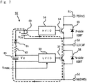
Fig. 7 is a circuit diagram showing the configuration of a bootstrap circuit implemented in an inverter. -
Fig. 8 is a timing chart showing the relationships among voltages in the bootstrap circuit when performing an initial charge. -
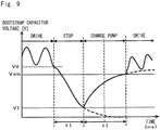
Fig. 9 is a diagram showing the voltage waveform of a bootstrap capacitor. -
Fig. 10 is a flowchart showing a position command process performed by the controller. -
Fig. 11 is a diagram showing supplementary position detection control using a second position detection sensor performed when a first position detection sensor is located in an irregular section. -
Fig. 12 includes schematic diagrams showing bogie trucks, in whichFig. 12(A) shows the positions of the bogie trucks when the rail is linear; andFig. 12(B) shows the positions of the bogie trucks when the rail is curved. - Hereafter, an embodiment of the present invention will be described with reference to the drawings.
-
Fig. 1 is a block diagram showing a moving body system according to the present embodiment. The moving body system shown inFig. 1 is a system using secondary-side-on-ground type linear motors. This moving body system includes avehicle 1 serving as a moving body and arail 2 serving as the movement path of the moving body.Magnets 3 with north poles andmagnets 3 with south poles are alternately disposed in a row with a predetermined pitch on therail 2. The moving body system shown inFig. 1 is, for example, a ceiling traveling vehicle system in which avehicle 1 travels along arail 2 installed on the ceiling. In the present embodiment, it is assumed that the moving body system includes arail 2 having a length of several km and 300 to 400vehicles 1. The moving body of the present embodiment is not limited to thevehicle 1 and may be any vehicles other than thevehicle 1 or moving bodies such as a robot arm. - The
vehicle 1 includes two motors (first motor 10A,second motor 10B), two magnet absence detection sensors (first magnetabsence detection sensor 11A, second magnetabsence detection sensor 11B), two position detection sensors (firstposition detection sensor 12A, secondposition detection sensor 12B), acontroller 13, and adrive controller 14. - The
first motor 10A andsecond motor 10B are linear motors which change the magnetic field so that themagnets 3 with south poles andmagnets 3 with north poles alternately disposed on therail 2 and the electrical angle thereof are synchronized. For example, three-phase (U, V, and W phases) linear synchronous motors are used as the linear motors. Thefirst motor 10A andsecond motor 10B are disposed in different positions in the moving direction of the vehicle 1 (in the direction of therail 2 shown inFig. 1 ). Thefirst motor 10A andsecond motor 10B are disposed in positions which are opposed tomagnets 3 on therail 2 in thevehicle 1 and which are adjacent to themagnets 3. Thefirst motor 10A is disposed in a front position in the moving direction of thevehicle 1, and thesecond motor 10B is disposed in a rear position in the moving direction of thevehicle 1. The front in the moving direction is referred to as front, and the rear in the moving direction is referred to as rear. - The first magnet
absence detection sensor 11A and second magnetabsence detection sensor 11B are detectors which detect themagnets 3 on therail 2. The first magnetabsence detection sensor 11A is a detector for detecting that thefirst motor 10A is located in a section in which nomagnet 3 is disposed on the rail 2 (an irregular section shown inFig. 3 ). The second magnetabsence detection sensor 11B is a detector for detecting that thesecond motor 10B is located in a section in which nomagnet 3 is disposed on the rail 2 (the irregular section shown inFig. 3 ). - The first magnet
absence detection sensor 11A and second magnetabsence detection sensor 11B include, for example, photosensors that detect objects (themagnets 3 with south poles andmagnets 3 with north poles inFig. 1 ) by receiving light emitted by a light emitter using a light receiver. The first magnetabsence detection sensor 11A and second magnetabsence detection sensor 11B are also disposed in positions which are opposed tomagnets 3 on therail 2 in thevehicle 1 and which are adjacent to themagnets 3. The first magnetabsence detection sensor 11A and the second magnetabsence detection sensor 11B output detection signals to thecontroller 13. - The first
position detection sensor 12A and the secondposition detection sensor 12B are position detectors which detect the position of thevehicle 1 on therail 2. When the firstposition detection sensor 12A is located in a section in whichmagnets 3 are disposed on the rail 2 (a section other than an irregular section shown inFig. 11 ), the position of thevehicle 1 is determined based on a position detected by the firstposition detection sensor 12A. When the firstposition detection sensor 12A is located in a section in which nomagnet 3 is disposed on the rail 2 (the irregular section shown inFig. 11 ), the position of thevehicle 1 is determined based on a position detected by the secondposition detection sensor 12B. - The first
position detection sensor 12A and the secondposition detection sensor 12B include, for example, magnetic pole detection sensors using Hall-effect devices (magnetic conversion devices; hereafter simply referred to as "Hall devices"). The detection heads of the firstposition detection sensor 12A and the secondposition detection sensor 12B are provided with Hall devices. When the detection heads move relatively to themagnets 3 with the movement of thevehicle 1, the direction of the magnetic field with respect to the magnetosensitive surfaces of the Hall devices changes. The Hall devices output electrical signals corresponding to the changed angle. The position of thevehicle 1 on therail 2 is detected based on the values (voltage values) of the electrical signals. The firstposition detection sensor 12A and the secondposition detection sensor 12B are also disposed in positions which are opposed tomagnets 3 on therail 2 in thevehicle 1 and which are adjacent to themagnets 3. The firstposition detection sensor 12A and the secondposition detection sensor 12B output detection signals to thecontroller 13. - The
controller 13 determines whether thefirst motor 10A is located in an irregular section, on the basis of the detection signal from the first magnetabsence detection sensor 11A. If thecontroller 13 determines that thefirst motor 10A is not located in any irregular section, it outputs, to thedrive controller 14, a drive command instructing thedrive controller 14 to drive thefirst motor 10A. In contrast, if thecontroller 13 determines that thefirst motor 10A is located in an irregular section, it outputs, to thedrive controller 14, a drive command instructing thedrive controller 14 to stop the drive of thefirst motor 10A. Similarly, thecontroller 13 determines whether thesecond motor 10B is located in an irregular section, on the basis of the detection signal from the second magnetabsence detection sensor 11B. If thecontroller 13 determines that thesecond motor 10B is not located in any irregular section, it outputs, to thedrive controller 14, a drive command instructing thedrive controller 14 to drive thesecond motor 10B. In contrast, if thecontroller 13 determines that thesecond motor 10B is located in an irregular section, it outputs, to thedrive controller 14, a drive command instructing thedrive controller 14 to stop the drive of thesecond motor 10B. As shown inFig. 6 , when the signal level of the drive command is high, themotor motor - Further, when the first
position detection sensor 12A is located in a section other than an irregular section, thecontroller 13 determines the position of thevehicle 1 on the basis of the detection signal from the firstposition detection sensor 12A. In contrast, when the firstposition detection sensor 12A is located in an irregular section, thecontroller 13 determines the position of thevehicle 1 on the basis of the detection signal from the secondposition detection sensor 12B. Then, based on the determined position of thevehicle 1, thecontroller 13 outputs, to thedrive controller 14, a position command instructing thedrive controller 14 to move thevehicle 1 to a movement position. - The
drive controller 14 controls the drive or stop of thefirst motor 10A on the basis of the drive command related to thefirst motor 10A from thecontroller 13. Thedrive controller 14 also controls the drive or stop of thesecond motor 10B on the basis of the drive command related to thesecond motor 10B from thecontroller 13. Thedrive controller 14 also controls the drive of thefirst motor 10A andsecond motor 10B so that thevehicle 1 moves to the movement position, on the basis of the position command from thecontroller 13. - While the first magnet
absence detection sensor 11A and the firstposition detection sensor 12A are disposed in positions adjacent to thefirst motor 10A in the example shown inFig. 1 , these sensors need not necessarily be disposed in such positions. Similarly, while the second magnetabsence detection sensor 11B and the secondposition detection sensor 12B are disposed in positions adjacent to thesecond motor 10B, these sensors need not necessarily be disposed in such positions. -
Fig. 2 is a block diagram showing the internal configurations of the controller and drive controller. In the configuration shown inFig. 2 , thecontroller 13 shown inFig. 1 includes aposition controller 131, amagnetless controller 132, and amotion controller 133. Thedrive controller 14 shown inFig. 1 includes afirst drive controller 14A that controls the drive of thefirst motor 10A and asecond drive controller 14B that controls the drive of thesecond motor 10B. - "MLD" shown in
Fig. 2 represents a magnetless detect, that is, the magnetabsence detection sensor Fig. 2 represents a position sensor, that is, theposition detection sensor - The
position controller 131 determines whether thefirst motor 10A is located in an irregular section, on the basis of the detection signal from the first magnetabsence detection sensor 11A. If theposition controller 131 determines that thefirst motor 10A is not located in any irregular section, it outputs a magnet absence detection status signal ("MLD-status" inFig. 2 ) indicating this status, to themagnetless controller 132 andmotion controller 133. Theposition controller 131 also determines whether thesecond motor 10B is located in an irregular section, on the basis of the detection signal from the second magnetabsence detection sensor 11B. If theposition controller 131 determines that thesecond motor 10B is not located in any irregular section, it outputs a magnet absence detection signal indicating this status, to themagnetless controller 132 andmotion controller 133. - Further, when the first
position detection sensor 12A is located in a section other than an irregular section, theposition controller 131 determines the position of thevehicle 1 on the basis of the detection signal from the firstposition detection sensor 12A. In contrast, when the firstposition detection sensor 12A is located in an irregular section, theposition controller 131 determines the position of thevehicle 1 on the basis of the detection signal from the secondposition detection sensor 12B. Theposition controller 131 then outputs position information indicating the determined current position of thevehicle 1 to themotion controller 133,first drive controller 14A, andsecond drive controller 14B. - The
magnetless controller 132 outputs, to thefirst drive controller 14A, a drive command instructing thefirst drive controller 14A to drive or stop (on/off of drive) thefirst motor 10A, on the basis of the magnet absence detection signal related to thefirst motor 10A from theposition controller 131. Themagnetless controller 132 also outputs, to thesecond drive controller 14B, a drive command instructing thesecond drive controller 14B to drive or stop thesecond motor 10B, on the basis of the magnet absence detection signal related to thesecond motor 10B from theposition controller 131. - The
motion controller 133 determines whether thefirst motor 10A andsecond motor 10B are located in an irregular section, on the basis of the magnet absence detection signals from theposition controller 131. Themotion controller 133 also checks the current position of thevehicle 1 on the basis of the position information from theposition controller 131. Themotion controller 133 then outputs, to thedrive controller motor vehicle 1 to a predetermined position (the movement position to which thevehicle 1 is to be moved). - The
first drive controller 14A includes aposition controller 141A, adifferentiator 142A, aspeed controller 143A, acurrent controller 144A, aninverter 145A, and acoil 146A. Theposition controller 141A receives data about the difference between the movement position indicated by the position command from themotion controller 133 and the current position indicated by the position information from the position controller 131 (position difference data). Theposition controller 141A then outputs speed data corresponding to the position difference data. Thespeed controller 143A receives data about the difference between the speed data from theposition controller 141A and data obtained by differentiating the position information from theposition controller 131 in thedifferentiator 142A (speed difference data). Thespeed controller 143A then outputs current value data corresponding to the speed difference data. - The
current controller 144A receives data of the difference between the current value data from thespeed controller 143A and feedback data corresponding to the present current value from a coil (load) 146A (that is, an actual current signal fed back based on the end-to-end voltage of a resistor which detects the current supplied to thecoil 146A) (current value difference data). Thecurrent controller 144A then outputs a drive current corresponding to the current value difference data. Theinverter 145A is a device which converts the direct drive current from thecurrent controller 144A into an alternating drive current. Theinverter 145A is a three-phase inverter using an intelligent power module (IPM). The alternating drive current converted by theinverter 145A is outputted to thefirst motor 10A. - The
second drive controller 14B includes aposition controller 141B, adifferentiator 142B, aspeed controller 143B, acurrent controller 144B, aninverter 145B, and a coil 146B. The configurations of the units in thesecond drive controller 14B are similar to those in thefirst drive controller 14A and therefore will not be described. -
Fig. 3 includes diagrams showing an irregular section on the rail, in whichFig. 3(A) is a diagram showing the state in which the first magnetabsence detection sensor 11A is not located in any irregular section; andFig. 3(B) is a diagram showing the state in which the first magnetabsence detection sensor 11A is located in an irregular section. As shown inFig. 3 , in the present embodiment,magnet units 3U are arranged on therail 2, and two sets of amagnet 31 with a north pole and amagnet 32 with a south pole (a total of four magnets 3) are disposed in eachmagnet unit 3U. When a worker installsmagnet units 3U as shown inFig. 3 , the workload of the worker is significantly reduced compared to that when the worker installsmagnets 3 one by one. On the other hand, when the worker arrangesmagnet units 3U on therail 2, the length of therail 2 must be an integral multiple of that of amagnet unit 3U. Thus, an irregular section in which nomagnet 3 is disposed would easily occur on therail 2. Further, the generated irregular section would have a long length. In the example shown inFig. 3 , there is generated an irregular section corresponding to about twice the pitch of a magnet. - In the example shown in
Fig. 3(A) , both the first magnetabsence detection sensor 11A and second magnetabsence detection sensor 11B have yet to enter the irregular section. Accordingly, both thefirst motor 10A andsecond motor 10B are being driven. In the example shown inFig. 3(B) , on the other hand, the second magnetabsence detection sensor 11B has yet to enter the irregular section, whereas the first magnetabsence detection sensor 11A has entered the irregular section. Accordingly, only thesecond motor 10B is being driven, and thefirst motor 10A is not being driven (that is, the drive of the first magnetabsence detection sensor 11A is being stopped). Subsequently, when thevehicle 1 moves in the traveling direction, the second magnetabsence detection sensor 11B enters the irregular section. In this case, the drive of thesecond motor 10B is stopped. - In the present embodiment, an "irregular section" refers to a section in which the poles of magnets are not disposed regularly, that is, a section in which
magnets 31 with north poles andmagnets 32 with south poles are not disposed regularly. Accordingly, "irregular sections" include sections in which nomagnet 3 is disposed, as well as sections in whichmagnets 31 with north poles andmagnets 32 with south poles are not alternately disposed. "Irregular sections" also include sections in whichmagnets 3 have weakening magnetic forces. Even in such sections, control is performed such that themotor - In the present embodiment, when one (e.g.,
first motor 10A) of the two motors, 10A and 10B, is located in an irregular section in which the poles ofmagnets 3 are not disposed regularly, the motor (e.g.,second motor 10B) other than the one motor is located in a section which is not the irregular section. According to this configuration, even when one motor is located in an irregular section, thevehicle 1 can be moved by driving the other motor. This configuration requires at least that the length of any irregular section be shorter than the distance between the two motors, 10A and 10B. Accordingly, when the distance between the two motors, 10A and 10B, is previously known, the length of any irregular section is set to a length shorter than that distance. -
Fig. 4 is a diagram showing the position in which a magnet absence detection sensor detects an irregular section. As shown inFig. 4 , it is assumed in the present embodiment that the pitch of one magnet 3 (amagnet 31 with a north pole and amagnet 32 with a south pole) in the moving direction of thevehicle 1 is 33 mm. When the magnetabsence detection sensor magnet 3 and then comes to a position corresponding to at least 1/4 of the pitch of amagnet 3, the magnet absence detection sensor detects that it has just entered an irregular section. The reason is that, assuming that the phase of the magnetic pole is 360° (2n) in the pitch of a set of amagnet 31 with a north pole and amagnet 32 with a south pole (the pitch of two magnets 3), when the magnetic pole and the electrical angle of themotor motor magnets 3 may adsorb each other, or thevehicle 1 may jump. When such a situation is repeated, themagnets 3 may be demagnetized. To avoid such an event, when themotor motor - Since the magnet
absence detection sensor motor absence detection sensor motor absence detection sensor motor absence detection sensor motor vehicle 1. - Next, the operation of the moving body system will be described.
-
Fig. 5 is a flowchart showing a drive command process performed by the controller.Fig. 6 is a timing chart showing the relationship between the detection of absence of a magnet and the drive of a motor. InFig. 6 , (F) represents the front, and (R) represents the rear. - As shown in
Fig. 5 , thecontroller 13 always checks the detection signal from the first magnetabsence detection sensor 11A (step S1). If the first magnetabsence detection sensor 11A has yet to detect the absence of a magnet (NO in step S1), thecontroller 13 continuously drives thefirst motor 10A (step S2). Specifically, thecontroller 13 continuously outputs, to thefirst drive controller 14A, a drive command instructing thefirst drive controller 14A to drive thefirst motor 10A. - In contrast, if the first magnet
absence detection sensor 11A detects the absence of a magnet (YES in step S1), thecontroller 13 causes the firstdrive control unit 14A to stop the drive of thefirst motor 10A (step S3) . Specifically, thecontroller 13 outputs, to thefirst drive controller 14A, a drive command instructing thefirst drive controller 14A to stop of the drive of thefirst motor 10A. - More specifically, steps S1 to S3 are performed as follows. Until time t1 in
Fig. 6 , thecontroller 13 determines that the first magnetabsence detection sensor 11A has yet to detect the absence of a magnet, since the level of the detection signal from the first magnetabsence detection sensor 11A is low. During this period of time, thecontroller 13 outputs, to thefirst drive controller 14A, a drive command instructing thefirst drive controller 14A to drive thefirst motor 10A. As shown inFig. 6 , the drive command instructing thefirst drive controller 14A to drive thefirst motor 10A is a high-level signal. At time t1 inFig. 6 , the level of the detection signal from the first magnetabsence detection sensor 11A is changed from the low level to a high level. Thus, thecontroller 13 determines that the first magnetabsence detection sensor 11A has detected the absence of a magnet. Thecontroller 13 then outputs, to thefirst drive controller 14A, a drive command instructing thefirst drive controller 14A to stop the drive of thefirst motor 10A. As shown inFig. 6 , the drive signal instructing thefirst drive controller 14A to stop thefirst motor 10A is a low-level signal. The time period from time t1 to time t2 inFig. 6 is the time lag between the time point when thecontroller 13 determines that the level of the detection signal has changed to the high level and the time point when thecontroller 13 changes the level of the drive command to a low level. If there is a distance between the first magnetabsence detection sensor 11A andfirst motor 10A, this time period is the time period from the time point when the first magnetabsence detection sensor 11A enters an irregular section to the time point when thefirst motor 10A enters the irregular section. - The
first drive controller 14A controls the status of thefirst motor 10A from the drive status to a stop status on the basis of the drive command from thecontroller 13. As shown inFig. 6 , when thefirst motor 10A is being driven, the level of the drive command is high; when thefirst motor 10A is being stopped, the level of the drive command is low. The time period from time t2 to time t3 inFig. 6 is the time lag between the time point when thefirst drive controller 14A determines that the level of the drive command has changed to the low level and the time point when thefirst drive controller 14A actually stops thefirst motor 10A. - At time t4 in
Fig. 6 , the detection signal from the first magnetabsence detection sensor 11A changes from the high level to a low level. Thus, thecontroller 13 determines that the first magnetabsence detection sensor 11A no longer detects the absence of a magnet. Thecontroller 13 then outputs, to thefirst drive controller 14A, a drive command instructing thefirst drive controller 14A to drive thefirst motor 10A. The time period from time t4 to time t5 inFig. 6 is the time lag between the time point when thecontroller 13 determines that the detection signal has changed to a low-level signal and the time point when thecontroller 13 changes the level of the drive command to a high level. If there is a distance between the first magnetabsence detection sensor 11A andfirst motor 10A, this time period is the time period from the time point when the magnetabsence detection sensor motor - The
first drive controller 14A controls the status of thefirst motor 10A from the stop status to a drive status on the basis of the drive command from thecontroller 13. The time period from time t5 to time t6 inFig. 6 is the time lag between the time point when thefirst drive controller 14A determines that the level of the drive command has changed to a high level and the time point when thefirst drive controller 14A actually drives thefirst motor 10A. - Referring back to
Fig. 5 , thecontroller 13 always checks the detection signal from the second magnetabsence detection sensor 11B (step S4). If the second magnetabsence detection sensor 11B has yet to detect the absence of a magnet (NO in step S4), thecontroller 13 continuously drives thesecond motor 10B (step S5). Specifically, thecontroller 13 continuously outputs, to thesecond drive controller 14B, a drive command instructing thesecond drive controller 14B to drive thesecond motor 10B. - In contrast, if the second magnet
absence detection sensor 11B detects the absence of a magnet (YES in step S4), thecontroller 13 stops the drive of thesecond motor 10B (step S5). Specifically, thecontroller 13 outputs, to thesecond drive controller 14B, a drive command instructing thesecond drive controller 14B to stop the drive of thesecond motor 10B. - More specifically, steps S4 to S6 are performed as follows. Until time t7 in
Fig. 6 , thecontroller 13 determines that the second magnetabsence detection sensor 11B has yet to detect the absence of a magnet, since the level of the detection signal from the second magnetabsence detection sensor 11B is low. During this time period, thecontroller 13 outputs, to thesecond drive controller 14B, a drive command instructing thesecond drive controller 14B to drive thesecond motor 10B. At time t7 inFig. 6 , the level of the detection signal from the second magnetabsence detection sensor 11B changes from the low level to a high level. Thus, thecontroller 13 determines that the second magnetabsence detection sensor 11B has detected the absence of a magnet. Thecontroller 13 then outputs, to thesecond drive controller 14B, a drive command instructing thesecond drive controller 14B to stop the drive of thesecond motor 10B. The time period from time t7 to time t8 inFig. 6 is the time lag between the time point when thecontroller 13 determines that the level of the detection signal has changed to the high level and the time point when thecontroller 13 changes the level of the drive command to a low level. If there is a distance between the second magnetabsence detection sensor 11B andsecond motor 10B, this time period is the time period from the time point when the second magnetabsence detection sensor 11B enters an irregular section to the time point when thesecond motor 10B enters the irregular section. - The
second drive controller 14B controls the status of thesecond motor 10B from the drive status to a stop status on the basis of the drive command from thecontroller 13. As shown inFig. 6 , when thesecond motor 10B is being driven, the level of the drive command is high; when thesecond motor 10B is being stopped, the level thereof is low. The time period from time t8 to time t9 inFig. 6 is the time lag between the time point when thesecond drive controller 14B determines that the level of the drive command has changed to the low level and the time point when thesecond drive controller 14B actually stops thesecond motor 10B. - At time t10 in
Fig. 6 , the level of the detection signal from the second magnetabsence detection sensor 11B changes from the high level to a low level. Thus, thecontroller 13 determines that the second magnetabsence detection sensor 11B no longer detects the absence of a magnet. Thecontroller 13 then outputs, to thesecond drive controller 14B, a drive command instructing thesecond drive controller 14B to drive thesecond motor 10B. The time period from time t10 to time t11 inFig. 6 is the time lag between the time point when thecontroller 13 determines that the level of the detection signal has changed to the low level and the time point when thecontroller 13 changes the level of the drive command to a high level. If there is a distance between the second magnetabsence detection sensor 11B andsecond motor 10B, this time period is the time period from the time point when the second magnetabsence detection sensor 11B exits an irregular section to the time point when thesecond motor 10B exits the irregular section. - The
second drive controller 14B controls the status of thesecond motor 10B from the stop status to a drive status on the basis of the drive command from thecontroller 13. The time period from time t11 to time t12 inFig. 6 is the time lag between the time point when thesecond drive controller 14B determines that the level of the drive command has changed to the high level and the time point when thesecond drive controller 14B actually drives thesecond motor 10B. - In the present embodiment, when the
first motor 10A orsecond motor 10B is located in an irregular section, thecontroller 13 stops the drive of thefirst motor 10A orsecond motor 10B. Accordingly, when thefirst motor 10A orsecond motor 10B is located in an irregular section, thefirst motor 10A orsecond motor 10B andmagnets 3 are prevented from losing synchronization. - Further, when the
first motor 10A orsecond motor 10B moves from the irregular section to a regular section (a section in which themagnets 31 with north poles andmagnets 32 with south poles are alternately regularly disposed), thecontroller 13 starts to drive thefirst motor 10A orsecond motor 10B. Specifically, at the time point when thefirst motor 10A orsecond motor 10B moves to the regular section (at the time point when the irregular section ends), thecontroller 13 outputs a drive command to thedrive controller 14, as well as newly outputs a position command to thedrive controller 14. Thus, thedrive controller 14 controls the drive of thefirst motor 10A orsecond motor 10B so that the position of thefirst motor 10A orsecond motor 10B and the positions ofmagnets 3 are synchronized. As a result, after thefirst motor 10A orsecond motor 10B passes through the irregular section, the electrical angle of thefirst motor 10A orsecond motor 10B and the poles ofmagnets 3 are prevented from losing synchronization. - Note that after the irregular section ends, the
drive control unit 14 may start to drive thefirst motor 10A orsecond motor 10B in the position of theseveralth magnet 3 in the regular section rather than starting to drive thefirst motor 10A orsecond motor 10B in the position of thefirst magnet 3 in the regular section. Specifically, at the time point when the first magnetabsence detection sensor 11A or second magnetabsence detection sensor 11B has continuously detectedseveral magnets 3 in the regular section, thecontroller 13 may output a drive command to thedrive controller 14, as well as may newly output a position command to thedrive controller 14. According to this configuration, when the regular section starts, the electrical angle of thefirst motor 10A orsecond motor 10B and the positions ofmagnets 3 can be reliably synchronized. - Next, there will be described the configuration of a bootstrap circuit implemented in each of the
inverters drive controllers Fig. 7 is a circuit diagram showing the configuration of a bootstrap circuit implemented in each inverter. Abootstrap circuit 50 is implemented in each of theinverters - On the other hand, by turning off one IGBT, the capacitor is discharged. For this reason, when starting the motor, it is necessary to ensure a sufficient time to apply, to the capacitor, an amount of charge required to drive the other IGBT. When all the IGBTs are turned off to completely stop the output of the
inverter motor inverter motor motor inverter motor Fig. 6 ). Accordingly, in the present embodiment, the stopped motor must be started quickly. - The configuration of the
bootstrap circuit 50 implemented in each inverter will be described. Thebootstrap circuit 50 includes abootstrap capacitor 60, a bootstrap diode (high-voltage, high-speed diode) 61, and a current limitingresistor 62. InFig. 7 , the collector terminal of a P-side IGBT 54 (hereafter referred to as the IGBT 54) and a P terminal 51 for receiving a voltage Vcc are connected together, and the emitter terminal of theIGBT 54 and anoutput terminal 53 for each phase (e.g., U terminal, etc.) are connected together. A high-voltage IC (HVIC) 56 is connected to the gate terminal of theIGBT 54. Adiode 55 for commutating the load current is connected between the collector terminal and emitter terminal of theIGBT 54. TheHVIC 56 is an IC circuit which directly drives the gate of theIGBT 54, which is the high voltage side, on the basis of an input signal from a microcomputer (the microcomputer of thedrive controller - The collector terminal of an N-side IGBT 57 (hereafter referred to as the IGBT 57) and the
output terminal 53 for each phase are connected together, and the emitter terminal of theIGBT 57 and anN terminal 52 having a ground-level potential are connected together. A low-voltage IC (LVIC) 59 is connected to the gate terminal of theIGBT 57. Adiode 58 for commutating the load current is connected between the collector terminal and emitter terminal of theIGBT 57. TheLVIC 59 is an IC circuit which directly drives the gate of theIGBT 57, which is the low voltage side, on the basis of an input signal from a microcomputer (the microcomputer of thedrive controller - The
bootstrap capacitor 60 is connected between an input connection point of theHVIC 56 and theoutput terminal 53 for each phase. Thebootstrap diode 61 and current limitingresistor 62 are connected in series between the input connection point of theHVIC 56 and an input connection point of theLVIC 59. Apower supply VD 63 is a power supply for driving theIGBT 57. Thepower supply VD 63 is connected between the collector terminal and emitter terminal of theIGBT 57. - When, during the drive of the
inverter HVIC 56 turns on theIGBT 55 and theLVIC 59 turns off theIGBT 57, the potential of theoutput terminal 53 for each phase becomes a Vcc-level potential. In contrast, when theHVIC 56 turns off theIGBT 55 and theLVIC 59 turns on theIGBT 57, the potential of theoutput terminal 53 for each phase becomes a ground-level potential. By repeatedly performing these operations, pulse width modulation (PWM) control is performed. -
Fig. 8 is a timing chart showing the relationships among the voltages in the bootstrap circuit when performing an initial charge. From initial time point T1, first, the voltage Vcc gradually increases, and the voltage VD increases. At time point T2, the voltage Vcc becomes a predetermined voltage, and the microcomputer inputs a pulse voltage VIN (N) to theLVIC 59. When the pulse voltage VIN(N) is inputted to theLVIC 59, theLVIC 59 drives theIGBT 57, which is then turned on. When theIGBT 57 is turned on, the current flows in the form of a loop as shown inFig. 7 , so that thebootstrap capacitor 60 is charged. As thebootstrap capacitor 60 is charged, the charge voltage VDB of thebootstrap capacitor 60 gradually increases. At time point T3, theHVIC 56 drives and turns on theIGBT 54. Thus, the amount of charge of thebootstrap capacitor 60 is used to drive theUGBT 54, so that the charge voltage VDB gradually decreases. -
Fig. 9 is a diagram showing the voltage waveform of the bootstrap capacitor. As shown inFig. 9 , when the motor is in a drive status (inverter bootstrap capacitor 60 repeatedly increases and decreases. The charge voltage VDB must be a voltage Vmin or more so that thebootstrap capacitor 60 serves as a power supply for driving theIGBT 54. - When the motor is placed in a stop status (the drive of the
inverter bootstrap capacitor 60 gradually decreases. Subsequently, theIGBT 57 is turned on before the motor is placed in a drive status. Thus, the charge voltage VDB of thebootstrap capacitor 60 gradually increases. At the time point when the charge voltage VDB becomes the voltage value Vmin, the drive of theinverter - As shown in
Fig. 9 , when the motor makes a transition from the drive status to the stop status, the value V1 of the charge voltage after a time τ1 elapsed since the time point of the stop of the motor (specifically, the time point of turn-off of the IGBT 57) (that is, after the time period during which the motor has been stopped) becomes V1=F(τ1,V0) due to the discharge characteristics of the capacitor. - The value V2 of the charge voltage VDB after a time τ2 elapsed since the restart of the charge pump becomes V2=G(τ2,V1) due to the charge pump characteristics of the capacitor. By solving this equation with respect to τ2, τ2=g(V1,V2) is obtained. Assuming that the voltage required to drive the P-
side IGBT 54 is Vmin, τ2=g(F(τ1,V0),Vmin) is calculated. Typically, a voltage value V0 is designed as the lowest value during the drive and calculated using an equation τ2=f(τ1) as a fixed value along with the voltage value Vmin. - Thus, the motor can be placed in a drive status at the time point when the value V2 of the charge voltage of VDB becomes the voltage value Vmin or more after the restart of the charge pump. Accordingly, by determining the charge time τ2 in accordance with the time τ1 during which the motor has been stopped (the time during which the
bootstrap capacitor 60 has been discharged), theIGBT 54 can be turned on reliably with the shortest time. - To realize this configuration, the microcomputer or the like of the
drive controller 14 measures the time from the time point when the P-side IGBT 57 is turned off to the time point when the charge pump is started and calculates a charge time corresponding to the measured time. Then, thebootstrap capacitor 60 is charged with the charge time calculated by the microcomputer or the like. -
Fig. 10 is a flowchart showing a position command process performed by the controller. As shown inFig. 10 , thecontroller 13, as described above, always monitors the detection signals from the firstposition detection sensor 12A and secondposition detection sensor 12B. Thecontroller 13 determines the current position of thevehicle 1 on the basis of the detection signal from the firstposition detection sensor 12A (step S11). - The
controller 13 also determines whether the firstposition detection sensor 12A is located in an irregular section, on the basis of the detection signal from the firstposition detection sensor 12A (step S12). If thecontroller 13 determines that the firstposition detection sensor 12A is not located in any irregular section (NO in step S12), it outputs a position command indicating the movement position of thevehicle 1 to thedrive controller 14 on the basis of the current position of thevehicle 1 determined in step S11 (step S15). Specifically, themotion controller 133 of thecontroller 13 outputs a position command to thefirst drive controller 14A, provided that themotion controller 133 has received, from theposition controller 131, a magnet absence detection status signal indicating that thefirst motor 10A is not located in any irregular section. Similarly, themotion controller 133 outputs a position command to thesecond drive controller 14B, provided that themotion controller 133 has received, from theposition controller 131, a magnet absence detection status signal indicating that thesecond motor 10B is not located in any irregular section. - In contrast, if the
controller 13 determines that the firstposition detection sensor 12A is located in an irregular section (YES in step S12), it determines the moving distance in the irregular section, of thevehicle 1 on the basis of the detection signal from the secondposition detection sensor 12B (step S13). Thecontroller 13 then determines the current position of thevehicle 1 from the moving distance in the irregular section, of the vehicle 1 (step S14). That is, when the firstposition detection sensor 12A (the first position detector) is located in the irregular section, thecontroller 13 determines the moving distance in the irregular section, of the vehicle 1 (the moving body) on the basis of a position detected by the secondposition detection sensor 12B (the second position detector) and determines the position of the vehicle 1 (the moving body) on the basis of the determined moving distance. Thecontroller 13 then outputs a position command indicating the movement position of thevehicle 1 to thedrive controller 14 on the basis of the current position of thevehicle 1 determined in step S14 (step S15). -
Fig. 11 is a diagram showing supplementary position detection control using the second position detection sensor performed when the first position detection sensor is located in an irregular section. When the firstposition detection sensor 12A is not located in any irregular section (NO in step S12), thecontroller 13 determines the current position of thevehicle 1 on the basis of the detection signal from the firstposition detection sensor 12A (step S11). Specifically, the firstposition detection sensor 12A outputs, to the controller 13 (in this case, the position controller 131), a detection signal which corresponds to a voltage value from the Hall device and which varies with the movement of thevehicle 1; for example, when thevehicle 1 is traveling at a constant speed, the firstposition detection sensor 12A outputs a detection signal which varies in the same cycle; and thecontroller 13 then determines the number ofmagnets 3 through which thevehicle 1 has passed, by counting (that is, incrementing) changes in the detection signal from the firstposition detection sensor 12A and thus determines the position of thevehicle 1. - In
Fig. 11 , thecontroller 13 determines a local position of thevehicle 1 by unit of one set of amagnet 31 with a north pole and amagnet 32 with a south pole and then sums up (consolidates) the local positions and thus determines the position of thevehicle 1. - Whether the first
position detection sensor 12A is located in an irregular section is determined as follows. That is, thecontroller 13 compares the changes in the detection signal of the firstposition detection sensor 12A and the changes in the detection signal of the secondposition detection sensor 12B; if there is disagreement in changes between these detection signals, thecontroller 13 determines that one of thedetection sensors controller 13 then determines which of thedetection sensors vehicle 1. - When the first
position detection sensor 12A is located in the irregular section as shown inFig. 11 (YES in step S12), thecontroller 13 changes the position detection sensor used to determine the position of thevehicle 1 from the firstposition detection sensor 12A to the secondposition detection sensor 12B. At this time, the firstposition detection sensor 12A is located in the irregular section, whereas the secondposition detection sensor 12B is not located in the irregular section. Thus, the moving distance of thevehicle 1 can be determined using the secondposition detection sensor 12B. As shownFig. 11 , the length of an irregular section is shorter than the distance between the firstposition detection sensor 12A (the first position detector) and the secondposition detection sensor 12B (the second position detector) in the moving direction of thevehicle 1. - As described above, the
controller 13 determines the moving distance in the irregular section, of thevehicle 1 on the basis of the detection signal from the secondposition detection sensor 12B (step S13) and determines the current position of thevehicle 1 from the moving distance in the irregular section, of the vehicle 1 (step S14). Specifically, thecontroller 13 determines the number ofmagnets 3 through which thevehicle 1 has passed, by counting (that is, incrementing) changes in the detection signal from the secondposition detection sensor 12B and thus determines the moving distance of thevehicle 1; and thecontroller 13 then determines the position of thevehicle 1 by adding the moving distance of thevehicle 1 to the consolidated position of thevehicle 1. Note that if the detection signal of the secondposition detection sensor 12B is used, the position of thevehicle 1 may be determined based on the distance between the firstposition detection sensor 12A and secondposition detection sensor 12B. Specifically, thecontroller 13 determines the consolidated position of thevehicle 1 on the basis of not only the detection signal from the firstposition detection sensor 12A but also the detection signal from the secondposition detection sensor 12B; when the firstposition detection sensor 12A is located in any irregular section, thecontrol unit 13 adds the distance between the firstposition detection sensor 12A and secondposition detection sensor 12B to the consolidated position of thevehicle 1 calculated based on the detection signal from the secondposition detection sensor 12B; and thus the consolidated position of thevehicle 1 based on the detection signal of the firstposition detection sensor 12A is determined. -
Fig. 12 includes schematic diagrams showing bogie trucks, in whichFig. 12(A) shows the positions of the bogie trucks when the rail is linear; andFig. 12(B) shows the positions of the bogie trucks when the rail is curved. The contact part of avehicle 1 with arail 2 comprises bogie trucks each including a mechanism rotatable with respect to the body (not shown) of thevehicle 1. Note thatFig. 12 shows cases where therail 2 installed on the ceiling is seen from below. - As shown in
Fig. 12 , thevehicle 1 includes two bogie trucks, 100A and 100B. Thebogie truck 100A is rotatably coupled to the body of thevehicle 1 using acenter pin 101A. Thebogie truck 100B is rotatably coupled to the body of thevehicle 1 using acenter pin 101B. - An
intermediate part 110 is disposed between thebogie truck 100A andbogie truck 100B. Thebogie truck 100A andintermediate part 110 are coupled together using acoupler 111, and thebogie truck 100B andintermediate part 110 are coupled together using acoupler 112. Thecouplers Fig. 12 , a firstposition detection sensor 12A is mounted on a surface remote from theintermediate part 110 of thebogie truck 100A. A secondposition detection sensor 12B is mounted on a surface remote from theintermediate part 110 of thebogie truck 100B. - As shown in
Fig. 12 , the distance L between thecenter pin 101A of thebogie truck 100A and thecenter pin 101B of thebogie truck 100B does not vary between the case where therail 2 is linear [Fig. 12(A) ] and the case where therail 2 is curved [Fig. 12(B) ]. On the other hand, the distance between thebogie truck 100A andintermediate part 110 or the distance between thebogie truck 100B andintermediate part 110 varies between the case where therail 2 is linear [Fig. 12(A) ] and the case where therail 2 is curved [Fig. 12(B) ]. Accordingly, as shown inFig. 12 , the distance between theposition detection sensors rail 2 is linear [Fig. 12(A) ] and the case where therail 2 is curved [Fig. 12(B) ]. That is, the distance between theposition detection sensors rail 2 is linear [Fig. 12(A) ], whereas the distance between theposition detection sensors rail 2 is curved [Fig. 12(B) ]. - When the distance between the
position detection sensors rail 2 is linear or curved as described above, difficulty seems to occur in supplementary position detection control using the secondposition detection sensor 12B performed when the firstposition detection sensor 12A is located in an irregular section. In the present embodiment, however, thecontroller 13 determines the positions ofmagnets 3 by incrementing the detection signal from the firstposition detection sensor 12A and then determines the position of thevehicle 1 from the positions of themagnets 3. Thus, even when the distance between theposition detection sensors vehicle 1 is not displaced from the original position unless thecontroller 13 makes a mistake in the number ofmagnets 3 incremented based on the detection signal from the firstposition detection sensor 12A. - As described above, in the present embodiment, the
vehicle 1 includes the two motors, 10A and 10B, disposed in different positions in the moving direction; and when one of the two motors is located in an irregular section in which the poles ofmagnets 3 are not disposed regularly, the motor other than the one motor is located in a section which is not the irregular section. Thus, even when the one motor is located in the irregular section, thevehicle 1 can be moved by driving the other motor. As a result, the presence of an irregular section is allowed, and the length of the movement path is not limited to the pitch of a magnet. - Irregular sections include a section in which no
magnet 3 is disposed. Accordingly, thevehicle 1 can be driven normally even in a section in which nomagnet 3 is disposed on therail 2. Irregular sections also include a section in which magnets with south poles and magnets with north poles are not alternately disposed. Accordingly, thevehicle 1 can be driven normally even in a section in whichmagnets 3 are not regularly alternately disposed on therail 2. Further, thevehicle 1 includes thedrive controller 14, which stops the drive of themotor motor magnets 3 from losing synchronization in an irregular section, as well as to synchronize themotor magnets 3 after the irregular section ends. - Further, the
vehicle 1 includes thedetectors drive controller 14 stops the drive of themotor detector motor motor detectors - Further, the
detectors magnets 3 and therefore can accurately detect an irregular section using the emission and reception of light. Further, thedrive controller 14 includes thebootstrap circuit 50, and thebootstrap capacitor 60 of thebootstrap circuit 50 is charged with a charge time corresponding to the time period during which themotor motor - In the present embodiment, when the first
position detection sensor 12A is located in an irregular section in which the poles ofmagnets 3 are not disposed regularly, thecontroller 13 determines the position of thevehicle 1 on the basis of a position detected by the secondposition detection sensor 12B. Thus, even when an irregular section in which the position cannot be detected is present on themovement path 2, it is possible to determine the accurate position of thevehicle 1. - Further the second
position detection sensor 12B detects the position of thevehicle 1 by detecting the poles ofmagnets 3. Thus, it is possible to reliably determine the position of thevehicle 1 on amagnet 3 basis. Further, thecontroller 13 compares the position detected by the firstposition detection sensor 12A and the position detected by the secondposition detection sensor 12B and thus determines that one of the firstposition detection sensor 12A and secondposition detection sensor 12B is located in an irregular section. Thus, it is possible to reliably determine that one of the firstposition detection sensor 12A and secondposition detection sensor 12B is located in an irregular section. Further, irregular sections include a section in which nomagnet 3 is disposed. Thus, it is possible to reliably determine the position of thevehicle 1 even in a section in which nomagnet 3 is disposed. Further, irregular sections include a section in whichmagnets 31 with south poles andmagnets 32 with north poles are not alternately disposed. Thus, it is possible to reliably determine the position of thevehicle 1 even in a section in whichmagnets 31 with south poles andmagnets 32 with north poles are not alternately disposed. - While the embodiment has been described above, the present invention is not limited to the elements or the like shown in the drawings. The functions, purposes, or the like of the elements can be changed without departing from the scope of the invention.
- While the
detectors absence detection sensor 11A, second magnetabsence detection sensor 11B) include photosensors in the above embodiment, these detectors may include magnetic pole detection sensors using Hall devices in place of photosensors. In this case, the Hall device of each magnetic pole detection sensor detects an irregular section by detecting the distortion (disturbance) of the magnetic field in the irregular section. Thedetectors detectors - While the
position detectors position detection sensor 12A, secondposition detection sensor 12B) include magnetic pole detection sensors for detecting the magnetic pole in the above embodiment, these detectors may be composed of photosensors in place of magnetic pole detection sensors. While thecontroller 13 determines the positions ofmagnets 3 by incrementing the detection signal from theposition detector vehicle 1, other configurations may be employed. For example, theposition detector vehicle 1, and thecontroller 13 may determine the position of thevehicle 1 on the basis of the absolute value of the moving distance of thevehicle 1 detected by theposition detector vehicle 1 may be detected using an encoder or the like. - In the above embodiment, the first magnet
absence detection sensor 11A and second magnetabsence detection sensor 11B detect the presence or absence of amagnet 3 in an irregular section, and the firstposition detection sensor 12A and secondposition detection sensor 12B detect the position of thevehicle 1. Alternatively, one set of detection sensors may detect both the presence or absence of amagnet 3 in an irregular section and the position of thevehicle 1. That is, the magnetabsence detection sensors position detection sensors controller 13 determines that thefirst motor 10A is located in an irregular section, on the basis of a detection signal from a first detector and determines the position of thevehicle 1 on the basis of a signal from a second detector. Alternatively, thecontroller 13 determines that thesecond motor 10B is located in an irregular section, on the basis of a detection signal from the second detector and determines the position of thevehicle 1 on the basis of a detection signal from the first detector. According to these configurations, the number of detectors is reduced and thus the cost is reduced. Further, the process can be simplified. - In the above embodiment, when the first
position detection sensor 12A is located in an irregular section, the position of thevehicle 1 is determined using the secondposition detection sensor 12B. Specifically, thecontroller 13 determines the position of thevehicle 1 on the basis of the detection signal of the firstposition detection sensor 12A and, only when the firstposition detection sensor 12A is located in an irregular section, determines the position of thevehicle 1 on the basis of the detection signal of the secondposition detection sensor 12B in a supplementary manner. Alternatively, thecontroller 13 may determine respective local positions and consolidated positions on the basis of the detection signals of the two position detection sensors, 12A and 12B; and when one of the two position detection sensors, 12A and 12B, is located in an irregular section, thecontrol unit 13 may, in a supplementary manner, determine the other consolidated position on the basis of the detection signal of the position detection sensor which is not located in the irregular section. In this case, the position of thevehicle 1 can be determined more reliably. Further, the position of thefirst motor 10A may be determined by detecting the position using the firstposition detection sensor 12A corresponding to thefirst motor 10A, and the position of thesecond motor 10B may be determined by detecting the position using the secondposition detection sensor 12B corresponding to thesecond motor 10B. - While the two motors are provided with the
vehicle 1 in the above embodiment, three or more motors may be provided. Even in this case, when one of the multiple motors is located in an irregular section, the motors other than the one motor are not located in the irregular section. In this case also, a magnet absence detection sensor and a position detection sensor are preferably provided for each of the motors. - While the two magnet absence detection sensors, 11A and 11B, are provided so as to correspond to the two motors, 10A and 10B, only a single magnet absence detection sensor may be provided. In this case, the
controller 13 determines the timing when thefirst motor 10A is located in an irregular section, for example, on the basis of the timing when the magnet absence detection sensor detects the irregular section and the distance between the magnet absence detection sensor and thefirst motor 10A. Similarly, thecontroller 13 determines the timing when thesecond motor 10B is located in an irregular section, on the basis of the timing when the magnet absence detection sensor detects the irregular section and the distance between the magnet absence detection sensor and thesecond motor 10B. - While it is assumed in the above embodiment that the pitch between the
motors rail 2 installed on the ground. - While the two position detection sensors, 12A and 12B, are mounted on the vehicle 1 (
bogie trucks Fig. 12 , the position detection sensors may be mounted on positions other than such positions. Further, another position detection sensor may be mounted on theintermediate part 110. By using the detection sensor mounted on theintermediate part 110, the position of the vehicle 1 (the central position of the vehicle 1) can be detected more precisely. - In the above embodiment, the
vehicle 1 moves by the thrust generated by the two motors, 10A and 10B. Assuming that the thrust generated by the two motors, 10A and 10B, is 100%, the thrust generated by each motor (first motor 10A,second motor 10B) is 50%. When one of the two motors is located in an irregular section, the thrust of thevehicle 1 is reduced to 50% due to the stop of that motor. Even in this case, the drive control of thevehicle 1 is not significantly affected, since the time period during which the one of the two motors is located in the irregular section is short. Alternatively, when one of the two motors is located in an irregular section and thus the motor is stopped, drive control may be performed so that the thrust of the other motor is increased. For example, when one motor is located in an irregular section and thus the drive of the motor is stopped, control may be performed so that the thrust of the other motor is increased to 100% (doubled) or a thrust close to 100%. According to this configuration, even when one of the two motors is located in an irregular section, thevehicle 1 can travel without reducing the thrust. -
- 1 vehicle (moving body)
- 2 rail (movement path)
- 3 magnet
- 10A first motor (motor)
- 10B second motor (motor)
- 11A first magnet absence detection sensor (detector)
- 11B second magnet absence detection sensor (detector)
- 12A first position detection sensor (first position detector)
- 12B second position detection sensor (second position detector)
- 13 controller
- 14 drive controller
- 31 magnet with north pole
- 32 magnet with south pole
- 50 bootstrap circuit
- 60 bootstrap capacitor
Claims (9)
- A position detection device for detecting a position of a moving body (1) having a first motor (10A) and a second motor (10B) disposed in the moving body, moving on a movement path (2) on which magnets (32) with south poles and magnets (31) with north poles are alternately disposed, the device comprising:a first position detector (12A) disposed in the moving body (1) and configured to detect the position of the moving body (1) by detecting poles of the magnets (3, 31, 32);a second position detector (12B) disposed in the moving body (1), disposed in a different position from a position of the first position detector (12A) in a moving direction of the moving body (1), and configured to detect the position of the moving body (1); anda controller (13) configured to determine the position of the moving body (1) on a basis of a position detected by the second position detector (12B) when the first position detector (12A) is located in an irregular section in which the poles of the magnets (3, 31, 32) are not disposed regularly, characterized by a first magnet absence detection sensor (11A) and a second magnet absence detection sensor (11B),the first magnet absence detection sensor (11A) being a detector for detecting that the first motor (10A) being adjacent to the first position detector (12A) is located in a section in which no magnet (3) is disposed on the rail (2),
the second magnet absence detection sensor (11B) being a detector for detecting that the second motor (10B) being adjacent to the second position detector (12B) is located in a section in which no magnet (3) is disposed on the rail (2). - The position detection device of Claim 1, characterized in that the second position detector (12B) detects the position of the moving body (1) by detecting the poles of the magnets (3, 31, 32).
- The position detection device of Claim 1 or 2, characterized in that the controller (13) determines that one of the first position detector (12A) and second position detector (12B) is located in the irregular section by comparing a position detected by the first position detector (12A) and the position detected by the second position detector (12B).
- The position detection device of any one of Claims 1 to 3, characterized in that when the first position detector (12A) is located in the irregular section, the controller (13) determines a moving distance of the moving body (1) in the irregular section on the basis of the position detected by the second position detector (12B) and determines the position of the moving body (1) on the basis of the determined moving distance.
- The position detection device of any one of Claims 1 to 4, characterized in that the irregular section is a section in which the magnets (3, 31, 32) are not disposed.
- The position detection device of any one of Claims 1 to 4, characterized in that the irregular section is a section in which the magnets (32) with south poles and the magnets with north poles (31) are not alternately disposed.
- The position detection device of any one of Claims 1 to 6, characterized in that the irregular section is shorter than a distance between the first position detector (12A) and the second position detector (12B) in the moving direction.
- A method for detecting a position of a moving body (1) having a first motor (10A) and a second motor (10B) disposed in the moving body, moving on a movement path (2) on which magnets (32) with south poles and magnets (31) with north poles are alternately disposed, the method comprising:detecting, by a first position detector (12A) disposed in the moving body (1), the position of the moving body (1) by detecting poles of the magnets (3, 31, 32);detecting, by a second position detector (12B) disposed in the moving body (1) and disposed in a different position from a position of the first position detector (12A) in a moving direction of the moving body (1), the position of the moving body (1); anddetermining, by a controller (13), the position of the moving body (1) on a basis of a position detected by the second position detector (12B) when the first position detector (12A) is located in an irregular section in which the poles of the magnets (3, 31, 32) are not disposed regularly, characterized by a first magnet absence detection sensor (11A) detecting that the first motor (10A) being adjacent to the first position detector (12A) is located in a section in which no magnet (3) is disposed on the rail (2) and a second magnet absence detection sensor (11B) detecting that the second motor (10B) being adjacent to the second position detector (12B) is located in a section in which no magnet (3) is disposed on the rail (2).
- A moving body system comprising:a movement path (2) on which magnets (32) with south poles and magnets (31) with north poles are alternately disposed; anda moving body (1) capable of moving along the movement path (2), characterized in that the moving body (1) comprises the position detection device of any one of Claims 1 to 7.
Applications Claiming Priority (2)
| Application Number | Priority Date | Filing Date | Title |
|---|---|---|---|
| JP2013089409A JP6314372B2 (en) | 2013-04-22 | 2013-04-22 | POSITION DETECTION DEVICE, POSITION DETECTION METHOD, AND MOBILE BODY SYSTEM |
| PCT/JP2014/059844 WO2014175033A1 (en) | 2013-04-22 | 2014-04-03 | Position detection device, position detection method and moving body system |
Publications (3)
| Publication Number | Publication Date |
|---|---|
| EP2990258A1 EP2990258A1 (en) | 2016-03-02 |
| EP2990258A4 EP2990258A4 (en) | 2016-12-14 |
| EP2990258B1 true EP2990258B1 (en) | 2018-11-28 |
Family
ID=51791614
Family Applications (1)
| Application Number | Title | Priority Date | Filing Date |
|---|---|---|---|
| EP14787645.2A Active EP2990258B1 (en) | 2013-04-22 | 2014-04-03 | Position detection device, position detection method and moving body system |
Country Status (9)
| Country | Link |
|---|---|
| US (1) | US9871434B2 (en) |
| EP (1) | EP2990258B1 (en) |
| JP (1) | JP6314372B2 (en) |
| KR (1) | KR101870218B1 (en) |
| CN (1) | CN105142969B (en) |
| IL (1) | IL242190B (en) |
| SG (1) | SG11201508624QA (en) |
| TW (1) | TWI646309B (en) |
| WO (1) | WO2014175033A1 (en) |
Families Citing this family (14)
| Publication number | Priority date | Publication date | Assignee | Title |
|---|---|---|---|---|
| EP3339088B1 (en) * | 2015-08-21 | 2020-01-08 | Murata Machinery, Ltd. | Mobile body |
| JP6206458B2 (en) | 2015-08-21 | 2017-10-04 | 村田機械株式会社 | MOBILE BODY AND MOBILE BODY POSITION DETECTING METHOD |
| JP6225961B2 (en) * | 2015-08-21 | 2017-11-08 | 村田機械株式会社 | Moving body |
| JP6191665B2 (en) * | 2015-08-21 | 2017-09-06 | 村田機械株式会社 | Moving body |
| KR102146023B1 (en) * | 2016-01-07 | 2020-08-19 | 엘지이노텍 주식회사 | Motor and electronic power steering system having the same |
| DE102016203854A1 (en) * | 2016-03-09 | 2017-09-14 | Festo Ag & Co. Kg | Conveyor |
| JP6840984B2 (en) | 2016-10-20 | 2021-03-10 | 村田機械株式会社 | Linear motor system, mobile system, and method of estimating electrical angle |
| CN106643644B (en) * | 2016-11-14 | 2020-02-07 | 西安建筑科技大学 | PSD-based automatic monitoring device and monitoring method for rail in tunnel operation period |
| TWI620916B (en) * | 2016-11-17 | 2018-04-11 | Absolute position sensing read head device | |
| TWI611165B (en) * | 2016-12-21 | 2018-01-11 | 國家中山科學研究院 | Building block potentiometer |
| US10304599B2 (en) | 2017-06-22 | 2019-05-28 | National Chung Shan Institute Of Science And Technology | Modular potentiometer |
| US10889449B2 (en) | 2017-09-25 | 2021-01-12 | Canon Kabushiki Kaisha | Transport system and manufacturing method of article |
| JP7020258B2 (en) * | 2018-04-06 | 2022-02-16 | 村田機械株式会社 | Position detection system and driving system |
| KR102324106B1 (en) * | 2018-06-26 | 2021-11-08 | 어플라이드 머티어리얼스, 인코포레이티드 | A distance sensor for measuring a distance to a ferromagnetic element, a magnetic levitation system, and a method for measuring a distance to a ferromagnetic element |
Family Cites Families (22)
| Publication number | Priority date | Publication date | Assignee | Title |
|---|---|---|---|---|
| JPH0810962B2 (en) * | 1984-06-29 | 1996-01-31 | 株式会社日立製作所 | Linear motor traveling device |
| JPH0630522B2 (en) * | 1985-11-21 | 1994-04-20 | 神鋼電機株式会社 | Linear motor type transport device |
| JPH07112321B2 (en) * | 1986-07-15 | 1995-11-29 | 財団法人鉄道総合技術研究所 | Position detector |
| JPH07120194B2 (en) | 1988-03-31 | 1995-12-20 | 株式会社椿本チエイン | Driving control method and apparatus for automatic guided vehicle |
| JP2958988B2 (en) * | 1989-09-22 | 1999-10-06 | 日本鋼管株式会社 | How to restart capsule |
| FR2657201B1 (en) * | 1990-01-12 | 1995-05-24 | Otis Elevator Co | LINEAR DRIVE MOTOR WITH PERMANENT MAGNETS AND ITS APPLICATIONS. |
| US5023495A (en) * | 1990-04-17 | 1991-06-11 | Hitachi Metals & Shicoh Engine | Moving-magnet type linear d.c. brushless motor having plural moving elements |
| JPH04198713A (en) * | 1990-11-28 | 1992-07-20 | Furukawa Electric Co Ltd:The | Position detecting method for magneticaly levitated running body |
| JPH06217592A (en) * | 1993-01-14 | 1994-08-05 | Hitachi Ltd | Fixed point stop method for linear synchronous motor type vehicle |
| JP3235708B2 (en) * | 1995-09-28 | 2001-12-04 | 株式会社ダイフク | Transfer equipment using linear motor |
| JP3436070B2 (en) * | 1997-05-15 | 2003-08-11 | 株式会社ダイフク | Transfer equipment |
| JP3349137B2 (en) * | 1999-10-13 | 2002-11-20 | 東海旅客鉄道株式会社 | Vehicle propulsion device |
| JP4239382B2 (en) * | 2000-08-24 | 2009-03-18 | 株式会社Ihi | Transport device |
| JP4506319B2 (en) | 2004-07-15 | 2010-07-21 | ムラテックオートメーション株式会社 | Linear motor type conveyor |
| JP4214533B2 (en) * | 2006-08-10 | 2009-01-28 | 村田機械株式会社 | Mobile system |
| DK2228629T3 (en) * | 2007-02-07 | 2017-11-06 | Sew Eurodrive Gmbh & Co Kg | System and method for determining the position of an engine part |
| US7804210B2 (en) * | 2008-03-25 | 2010-09-28 | Bose Corporation | Position measurement using magnetic fields |
| JP4438882B2 (en) * | 2008-05-12 | 2010-03-24 | 村田機械株式会社 | Mobile system |
| JP4941790B2 (en) * | 2009-08-28 | 2012-05-30 | 村田機械株式会社 | Mobile system |
| JP5421709B2 (en) * | 2009-09-30 | 2014-02-19 | Thk株式会社 | Linear motor drive system and control method |
| JP5379748B2 (en) | 2010-06-03 | 2013-12-25 | Ntn株式会社 | Magnetic encoder |
| KR20130085041A (en) * | 2010-10-26 | 2013-07-26 | 무라다기카이가부시끼가이샤 | Distributed linear motor system |
-
2013
- 2013-04-22 JP JP2013089409A patent/JP6314372B2/en active Active
-
2014
- 2014-04-03 CN CN201480022153.4A patent/CN105142969B/en active Active
- 2014-04-03 EP EP14787645.2A patent/EP2990258B1/en active Active
- 2014-04-03 WO PCT/JP2014/059844 patent/WO2014175033A1/en active Application Filing
- 2014-04-03 SG SG11201508624QA patent/SG11201508624QA/en unknown
- 2014-04-03 US US14/785,839 patent/US9871434B2/en active Active
- 2014-04-03 KR KR1020157030313A patent/KR101870218B1/en active IP Right Grant
- 2014-04-16 TW TW103113856A patent/TWI646309B/en active
-
2015
- 2015-10-20 IL IL242190A patent/IL242190B/en active IP Right Grant
Non-Patent Citations (1)
| Title |
|---|
| None * |
Also Published As
| Publication number | Publication date |
|---|---|
| EP2990258A4 (en) | 2016-12-14 |
| JP6314372B2 (en) | 2018-04-25 |
| CN105142969A (en) | 2015-12-09 |
| CN105142969B (en) | 2018-01-09 |
| JP2014217077A (en) | 2014-11-17 |
| KR101870218B1 (en) | 2018-06-22 |
| KR20150132876A (en) | 2015-11-26 |
| IL242190B (en) | 2019-05-30 |
| EP2990258A1 (en) | 2016-03-02 |
| SG11201508624QA (en) | 2015-11-27 |
| US9871434B2 (en) | 2018-01-16 |
| TWI646309B (en) | 2019-01-01 |
| US20160072367A1 (en) | 2016-03-10 |
| TW201447237A (en) | 2014-12-16 |
| WO2014175033A1 (en) | 2014-10-30 |
Similar Documents
| Publication | Publication Date | Title |
|---|---|---|
| EP2990258B1 (en) | Position detection device, position detection method and moving body system | |
| EP2990259B1 (en) | Moving body system and drive method of moving body | |
| JP4941790B2 (en) | Mobile system | |
| KR101584022B1 (en) | Transfer system | |
| US6462495B1 (en) | Controlling a brushless DC motor | |
| US9391551B2 (en) | Apparatus to detect the zero-cross of the BEMF of a three-phase electric motor and related method | |
| US11027615B2 (en) | System and method for improving travel across joints in a track for a linear motion system | |
| US20210032077A1 (en) | Position-determining system and method for ascertaining a car position of an elevator car | |
| CN102906990B (en) | Determine the method and apparatus of the phase current zero passage of electronic commutation motor, especially definite motor rotor position | |
| US8461826B2 (en) | Device for the detection quadrature signals | |
| JP2012016106A (en) | Alignment system of noncontact power supply device | |
| US9729100B2 (en) | Mobile body and mobile body system | |
| US9768721B2 (en) | Mobile body and mobile body system | |
| CN117477992A (en) | Control circuit of brushless DC motor and method for detecting initial rotor position of motor | |
| Pottharst et al. | Drive control and position measurement of RailCab vehicles driven by linear motors | |
| CN110950003A (en) | Linear transmission system and control method thereof |
Legal Events
| Date | Code | Title | Description |
|---|---|---|---|
| PUAI | Public reference made under article 153(3) epc to a published international application that has entered the european phase |
Free format text: ORIGINAL CODE: 0009012 |
|
| 17P | Request for examination filed |
Effective date: 20151016 |
|
| AK | Designated contracting states |
Kind code of ref document: A1 Designated state(s): AL AT BE BG CH CY CZ DE DK EE ES FI FR GB GR HR HU IE IS IT LI LT LU LV MC MK MT NL NO PL PT RO RS SE SI SK SM TR |
|
| AX | Request for extension of the european patent |
Extension state: BA ME |
|
| DAX | Request for extension of the european patent (deleted) | ||
| A4 | Supplementary search report drawn up and despatched |
Effective date: 20161110 |
|
| RIC1 | Information provided on ipc code assigned before grant |
Ipc: B61B 13/06 20060101ALI20161104BHEP Ipc: G01D 5/20 20060101ALI20161104BHEP Ipc: H02K 11/215 20160101ALI20161104BHEP Ipc: B61B 13/08 20060101ALI20161104BHEP Ipc: B60L 13/03 20060101AFI20161104BHEP Ipc: H02K 41/03 20060101ALI20161104BHEP Ipc: B60L 15/00 20060101ALI20161104BHEP Ipc: B65G 54/02 20060101ALI20161104BHEP |
|
| STAA | Information on the status of an ep patent application or granted ep patent |
Free format text: STATUS: EXAMINATION IS IN PROGRESS |
|
| 17Q | First examination report despatched |
Effective date: 20171124 |
|
| REG | Reference to a national code |
Ref country code: DE Ref legal event code: R079 Ref document number: 602014037033 Country of ref document: DE Free format text: PREVIOUS MAIN CLASS: B60L0013030000 Ipc: G01D0005140000 |
|
| RIC1 | Information provided on ipc code assigned before grant |
Ipc: G01D 5/14 20060101AFI20180503BHEP Ipc: H02K 41/03 20060101ALI20180503BHEP Ipc: B60L 13/03 20060101ALI20180503BHEP Ipc: G01D 5/20 20060101ALI20180503BHEP Ipc: H02K 11/215 20160101ALI20180503BHEP Ipc: B60L 15/00 20060101ALI20180503BHEP |
|
| GRAP | Despatch of communication of intention to grant a patent |
Free format text: ORIGINAL CODE: EPIDOSNIGR1 |
|
| STAA | Information on the status of an ep patent application or granted ep patent |
Free format text: STATUS: GRANT OF PATENT IS INTENDED |
|
| INTG | Intention to grant announced |
Effective date: 20180627 |
|
| RIN1 | Information on inventor provided before grant (corrected) |
Inventor name: YAMADA, YASUTAKE Inventor name: AZUMA, YOSHIYUKI |
|
| GRAJ | Information related to disapproval of communication of intention to grant by the applicant or resumption of examination proceedings by the epo deleted |
Free format text: ORIGINAL CODE: EPIDOSDIGR1 |
|
| STAA | Information on the status of an ep patent application or granted ep patent |
Free format text: STATUS: EXAMINATION IS IN PROGRESS |
|
| INTC | Intention to grant announced (deleted) | ||
| GRAP | Despatch of communication of intention to grant a patent |
Free format text: ORIGINAL CODE: EPIDOSNIGR1 |
|
| STAA | Information on the status of an ep patent application or granted ep patent |
Free format text: STATUS: GRANT OF PATENT IS INTENDED |
|
| GRAS | Grant fee paid |
Free format text: ORIGINAL CODE: EPIDOSNIGR3 |
|
| GRAA | (expected) grant |
Free format text: ORIGINAL CODE: 0009210 |
|
| STAA | Information on the status of an ep patent application or granted ep patent |
Free format text: STATUS: THE PATENT HAS BEEN GRANTED |
|
| INTG | Intention to grant announced |
Effective date: 20181005 |
|
| AK | Designated contracting states |
Kind code of ref document: B1 Designated state(s): AL AT BE BG CH CY CZ DE DK EE ES FI FR GB GR HR HU IE IS IT LI LT LU LV MC MK MT NL NO PL PT RO RS SE SI SK SM TR |
|
| REG | Reference to a national code |
Ref country code: CH Ref legal event code: EP |
|
| REG | Reference to a national code |
Ref country code: AT Ref legal event code: REF Ref document number: 1070753 Country of ref document: AT Kind code of ref document: T Effective date: 20181215 |
|
| REG | Reference to a national code |
Ref country code: DE Ref legal event code: R096 Ref document number: 602014037033 Country of ref document: DE |
|
| REG | Reference to a national code |
Ref country code: IE Ref legal event code: FG4D |
|
| REG | Reference to a national code |
Ref country code: NL Ref legal event code: MP Effective date: 20181128 |
|
| REG | Reference to a national code |
Ref country code: LT Ref legal event code: MG4D |
|
| REG | Reference to a national code |
Ref country code: AT Ref legal event code: MK05 Ref document number: 1070753 Country of ref document: AT Kind code of ref document: T Effective date: 20181128 |
|
| PG25 | Lapsed in a contracting state [announced via postgrant information from national office to epo] |
Ref country code: BG Free format text: LAPSE BECAUSE OF FAILURE TO SUBMIT A TRANSLATION OF THE DESCRIPTION OR TO PAY THE FEE WITHIN THE PRESCRIBED TIME-LIMIT Effective date: 20190228 Ref country code: HR Free format text: LAPSE BECAUSE OF FAILURE TO SUBMIT A TRANSLATION OF THE DESCRIPTION OR TO PAY THE FEE WITHIN THE PRESCRIBED TIME-LIMIT Effective date: 20181128 Ref country code: LV Free format text: LAPSE BECAUSE OF FAILURE TO SUBMIT A TRANSLATION OF THE DESCRIPTION OR TO PAY THE FEE WITHIN THE PRESCRIBED TIME-LIMIT Effective date: 20181128 Ref country code: FI Free format text: LAPSE BECAUSE OF FAILURE TO SUBMIT A TRANSLATION OF THE DESCRIPTION OR TO PAY THE FEE WITHIN THE PRESCRIBED TIME-LIMIT Effective date: 20181128 Ref country code: ES Free format text: LAPSE BECAUSE OF FAILURE TO SUBMIT A TRANSLATION OF THE DESCRIPTION OR TO PAY THE FEE WITHIN THE PRESCRIBED TIME-LIMIT Effective date: 20181128 Ref country code: AT Free format text: LAPSE BECAUSE OF FAILURE TO SUBMIT A TRANSLATION OF THE DESCRIPTION OR TO PAY THE FEE WITHIN THE PRESCRIBED TIME-LIMIT Effective date: 20181128 Ref country code: LT Free format text: LAPSE BECAUSE OF FAILURE TO SUBMIT A TRANSLATION OF THE DESCRIPTION OR TO PAY THE FEE WITHIN THE PRESCRIBED TIME-LIMIT Effective date: 20181128 Ref country code: IS Free format text: LAPSE BECAUSE OF FAILURE TO SUBMIT A TRANSLATION OF THE DESCRIPTION OR TO PAY THE FEE WITHIN THE PRESCRIBED TIME-LIMIT Effective date: 20190328 Ref country code: NO Free format text: LAPSE BECAUSE OF FAILURE TO SUBMIT A TRANSLATION OF THE DESCRIPTION OR TO PAY THE FEE WITHIN THE PRESCRIBED TIME-LIMIT Effective date: 20190228 |
|
| PG25 | Lapsed in a contracting state [announced via postgrant information from national office to epo] |
Ref country code: GR Free format text: LAPSE BECAUSE OF FAILURE TO SUBMIT A TRANSLATION OF THE DESCRIPTION OR TO PAY THE FEE WITHIN THE PRESCRIBED TIME-LIMIT Effective date: 20190301 Ref country code: PT Free format text: LAPSE BECAUSE OF FAILURE TO SUBMIT A TRANSLATION OF THE DESCRIPTION OR TO PAY THE FEE WITHIN THE PRESCRIBED TIME-LIMIT Effective date: 20190328 Ref country code: SE Free format text: LAPSE BECAUSE OF FAILURE TO SUBMIT A TRANSLATION OF THE DESCRIPTION OR TO PAY THE FEE WITHIN THE PRESCRIBED TIME-LIMIT Effective date: 20181128 Ref country code: RS Free format text: LAPSE BECAUSE OF FAILURE TO SUBMIT A TRANSLATION OF THE DESCRIPTION OR TO PAY THE FEE WITHIN THE PRESCRIBED TIME-LIMIT Effective date: 20181128 Ref country code: AL Free format text: LAPSE BECAUSE OF FAILURE TO SUBMIT A TRANSLATION OF THE DESCRIPTION OR TO PAY THE FEE WITHIN THE PRESCRIBED TIME-LIMIT Effective date: 20181128 |
|
| PG25 | Lapsed in a contracting state [announced via postgrant information from national office to epo] |
Ref country code: NL Free format text: LAPSE BECAUSE OF FAILURE TO SUBMIT A TRANSLATION OF THE DESCRIPTION OR TO PAY THE FEE WITHIN THE PRESCRIBED TIME-LIMIT Effective date: 20181128 |
|
| PG25 | Lapsed in a contracting state [announced via postgrant information from national office to epo] |
Ref country code: PL Free format text: LAPSE BECAUSE OF FAILURE TO SUBMIT A TRANSLATION OF THE DESCRIPTION OR TO PAY THE FEE WITHIN THE PRESCRIBED TIME-LIMIT Effective date: 20181128 Ref country code: IT Free format text: LAPSE BECAUSE OF FAILURE TO SUBMIT A TRANSLATION OF THE DESCRIPTION OR TO PAY THE FEE WITHIN THE PRESCRIBED TIME-LIMIT Effective date: 20181128 Ref country code: CZ Free format text: LAPSE BECAUSE OF FAILURE TO SUBMIT A TRANSLATION OF THE DESCRIPTION OR TO PAY THE FEE WITHIN THE PRESCRIBED TIME-LIMIT Effective date: 20181128 Ref country code: DK Free format text: LAPSE BECAUSE OF FAILURE TO SUBMIT A TRANSLATION OF THE DESCRIPTION OR TO PAY THE FEE WITHIN THE PRESCRIBED TIME-LIMIT Effective date: 20181128 |
|
| REG | Reference to a national code |
Ref country code: DE Ref legal event code: R097 Ref document number: 602014037033 Country of ref document: DE |
|
| PG25 | Lapsed in a contracting state [announced via postgrant information from national office to epo] |
Ref country code: RO Free format text: LAPSE BECAUSE OF FAILURE TO SUBMIT A TRANSLATION OF THE DESCRIPTION OR TO PAY THE FEE WITHIN THE PRESCRIBED TIME-LIMIT Effective date: 20181128 Ref country code: SK Free format text: LAPSE BECAUSE OF FAILURE TO SUBMIT A TRANSLATION OF THE DESCRIPTION OR TO PAY THE FEE WITHIN THE PRESCRIBED TIME-LIMIT Effective date: 20181128 Ref country code: SM Free format text: LAPSE BECAUSE OF FAILURE TO SUBMIT A TRANSLATION OF THE DESCRIPTION OR TO PAY THE FEE WITHIN THE PRESCRIBED TIME-LIMIT Effective date: 20181128 Ref country code: EE Free format text: LAPSE BECAUSE OF FAILURE TO SUBMIT A TRANSLATION OF THE DESCRIPTION OR TO PAY THE FEE WITHIN THE PRESCRIBED TIME-LIMIT Effective date: 20181128 |
|
| PLBE | No opposition filed within time limit |
Free format text: ORIGINAL CODE: 0009261 |
|
| STAA | Information on the status of an ep patent application or granted ep patent |
Free format text: STATUS: NO OPPOSITION FILED WITHIN TIME LIMIT |
|
| PG25 | Lapsed in a contracting state [announced via postgrant information from national office to epo] |
Ref country code: SI Free format text: LAPSE BECAUSE OF FAILURE TO SUBMIT A TRANSLATION OF THE DESCRIPTION OR TO PAY THE FEE WITHIN THE PRESCRIBED TIME-LIMIT Effective date: 20181128 |
|
| 26N | No opposition filed |
Effective date: 20190829 |
|
| REG | Reference to a national code |
Ref country code: CH Ref legal event code: PL |
|
| REG | Reference to a national code |
Ref country code: BE Ref legal event code: MM Effective date: 20190430 |
|
| GBPC | Gb: european patent ceased through non-payment of renewal fee |
Effective date: 20190403 |
|
| PG25 | Lapsed in a contracting state [announced via postgrant information from national office to epo] |
Ref country code: MC Free format text: LAPSE BECAUSE OF FAILURE TO SUBMIT A TRANSLATION OF THE DESCRIPTION OR TO PAY THE FEE WITHIN THE PRESCRIBED TIME-LIMIT Effective date: 20181128 Ref country code: LU Free format text: LAPSE BECAUSE OF NON-PAYMENT OF DUE FEES Effective date: 20190403 |
|
| PG25 | Lapsed in a contracting state [announced via postgrant information from national office to epo] |
Ref country code: GB Free format text: LAPSE BECAUSE OF NON-PAYMENT OF DUE FEES Effective date: 20190403 Ref country code: LI Free format text: LAPSE BECAUSE OF NON-PAYMENT OF DUE FEES Effective date: 20190430 Ref country code: CH Free format text: LAPSE BECAUSE OF NON-PAYMENT OF DUE FEES Effective date: 20190430 |
|
| PG25 | Lapsed in a contracting state [announced via postgrant information from national office to epo] |
Ref country code: FR Free format text: LAPSE BECAUSE OF NON-PAYMENT OF DUE FEES Effective date: 20190430 Ref country code: BE Free format text: LAPSE BECAUSE OF NON-PAYMENT OF DUE FEES Effective date: 20190430 |
|
| PG25 | Lapsed in a contracting state [announced via postgrant information from national office to epo] |
Ref country code: TR Free format text: LAPSE BECAUSE OF FAILURE TO SUBMIT A TRANSLATION OF THE DESCRIPTION OR TO PAY THE FEE WITHIN THE PRESCRIBED TIME-LIMIT Effective date: 20181128 |
|
| PG25 | Lapsed in a contracting state [announced via postgrant information from national office to epo] |
Ref country code: IE Free format text: LAPSE BECAUSE OF NON-PAYMENT OF DUE FEES Effective date: 20190403 |
|
| PG25 | Lapsed in a contracting state [announced via postgrant information from national office to epo] |
Ref country code: CY Free format text: LAPSE BECAUSE OF FAILURE TO SUBMIT A TRANSLATION OF THE DESCRIPTION OR TO PAY THE FEE WITHIN THE PRESCRIBED TIME-LIMIT Effective date: 20181128 |
|
| PG25 | Lapsed in a contracting state [announced via postgrant information from national office to epo] |
Ref country code: MT Free format text: LAPSE BECAUSE OF FAILURE TO SUBMIT A TRANSLATION OF THE DESCRIPTION OR TO PAY THE FEE WITHIN THE PRESCRIBED TIME-LIMIT Effective date: 20181128 Ref country code: HU Free format text: LAPSE BECAUSE OF FAILURE TO SUBMIT A TRANSLATION OF THE DESCRIPTION OR TO PAY THE FEE WITHIN THE PRESCRIBED TIME-LIMIT; INVALID AB INITIO Effective date: 20140403 |
|
| PG25 | Lapsed in a contracting state [announced via postgrant information from national office to epo] |
Ref country code: MK Free format text: LAPSE BECAUSE OF FAILURE TO SUBMIT A TRANSLATION OF THE DESCRIPTION OR TO PAY THE FEE WITHIN THE PRESCRIBED TIME-LIMIT Effective date: 20181128 |
|
| PGFP | Annual fee paid to national office [announced via postgrant information from national office to epo] |
Ref country code: DE Payment date: 20230420 Year of fee payment: 10 |