EP2989303B1 - Positive ignition engine and exhaust system comprising catalysed zone-coated filter substrate - Google Patents
Positive ignition engine and exhaust system comprising catalysed zone-coated filter substrate Download PDFInfo
- Publication number
- EP2989303B1 EP2989303B1 EP14719824.6A EP14719824A EP2989303B1 EP 2989303 B1 EP2989303 B1 EP 2989303B1 EP 14719824 A EP14719824 A EP 14719824A EP 2989303 B1 EP2989303 B1 EP 2989303B1
- Authority
- EP
- European Patent Office
- Prior art keywords
- zone
- washcoat
- filter
- substrate
- positive ignition
- Prior art date
- Legal status (The legal status is an assumption and is not a legal conclusion. Google has not performed a legal analysis and makes no representation as to the accuracy of the status listed.)
- Active
Links
Images


Classifications
-
- B—PERFORMING OPERATIONS; TRANSPORTING
- B01—PHYSICAL OR CHEMICAL PROCESSES OR APPARATUS IN GENERAL
- B01D—SEPARATION
- B01D53/00—Separation of gases or vapours; Recovering vapours of volatile solvents from gases; Chemical or biological purification of waste gases, e.g. engine exhaust gases, smoke, fumes, flue gases, aerosols
- B01D53/34—Chemical or biological purification of waste gases
- B01D53/92—Chemical or biological purification of waste gases of engine exhaust gases
- B01D53/94—Chemical or biological purification of waste gases of engine exhaust gases by catalytic processes
-
- F—MECHANICAL ENGINEERING; LIGHTING; HEATING; WEAPONS; BLASTING
- F01—MACHINES OR ENGINES IN GENERAL; ENGINE PLANTS IN GENERAL; STEAM ENGINES
- F01N—GAS-FLOW SILENCERS OR EXHAUST APPARATUS FOR MACHINES OR ENGINES IN GENERAL; GAS-FLOW SILENCERS OR EXHAUST APPARATUS FOR INTERNAL-COMBUSTION ENGINES
- F01N3/00—Exhaust or silencing apparatus having means for purifying, rendering innocuous, or otherwise treating exhaust
- F01N3/02—Exhaust or silencing apparatus having means for purifying, rendering innocuous, or otherwise treating exhaust for cooling, or for removing solid constituents of, exhaust
- F01N3/021—Exhaust or silencing apparatus having means for purifying, rendering innocuous, or otherwise treating exhaust for cooling, or for removing solid constituents of, exhaust by means of filters
- F01N3/033—Exhaust or silencing apparatus having means for purifying, rendering innocuous, or otherwise treating exhaust for cooling, or for removing solid constituents of, exhaust by means of filters in combination with other devices
- F01N3/035—Exhaust or silencing apparatus having means for purifying, rendering innocuous, or otherwise treating exhaust for cooling, or for removing solid constituents of, exhaust by means of filters in combination with other devices with catalytic reactors
-
- B—PERFORMING OPERATIONS; TRANSPORTING
- B01—PHYSICAL OR CHEMICAL PROCESSES OR APPARATUS IN GENERAL
- B01D—SEPARATION
- B01D46/00—Filters or filtering processes specially modified for separating dispersed particles from gases or vapours
- B01D46/24—Particle separators, e.g. dust precipitators, using rigid hollow filter bodies
-
- B—PERFORMING OPERATIONS; TRANSPORTING
- B01—PHYSICAL OR CHEMICAL PROCESSES OR APPARATUS IN GENERAL
- B01D—SEPARATION
- B01D53/00—Separation of gases or vapours; Recovering vapours of volatile solvents from gases; Chemical or biological purification of waste gases, e.g. engine exhaust gases, smoke, fumes, flue gases, aerosols
- B01D53/34—Chemical or biological purification of waste gases
- B01D53/92—Chemical or biological purification of waste gases of engine exhaust gases
- B01D53/94—Chemical or biological purification of waste gases of engine exhaust gases by catalytic processes
- B01D53/9404—Removing only nitrogen compounds
- B01D53/9409—Nitrogen oxides
- B01D53/9413—Processes characterised by a specific catalyst
-
- B—PERFORMING OPERATIONS; TRANSPORTING
- B01—PHYSICAL OR CHEMICAL PROCESSES OR APPARATUS IN GENERAL
- B01D—SEPARATION
- B01D53/00—Separation of gases or vapours; Recovering vapours of volatile solvents from gases; Chemical or biological purification of waste gases, e.g. engine exhaust gases, smoke, fumes, flue gases, aerosols
- B01D53/34—Chemical or biological purification of waste gases
- B01D53/92—Chemical or biological purification of waste gases of engine exhaust gases
- B01D53/94—Chemical or biological purification of waste gases of engine exhaust gases by catalytic processes
- B01D53/9404—Removing only nitrogen compounds
- B01D53/9409—Nitrogen oxides
- B01D53/9431—Processes characterised by a specific device
-
- B—PERFORMING OPERATIONS; TRANSPORTING
- B01—PHYSICAL OR CHEMICAL PROCESSES OR APPARATUS IN GENERAL
- B01D—SEPARATION
- B01D53/00—Separation of gases or vapours; Recovering vapours of volatile solvents from gases; Chemical or biological purification of waste gases, e.g. engine exhaust gases, smoke, fumes, flue gases, aerosols
- B01D53/34—Chemical or biological purification of waste gases
- B01D53/92—Chemical or biological purification of waste gases of engine exhaust gases
- B01D53/94—Chemical or biological purification of waste gases of engine exhaust gases by catalytic processes
- B01D53/9445—Simultaneously removing carbon monoxide, hydrocarbons or nitrogen oxides making use of three-way catalysts [TWC] or four-way-catalysts [FWC]
-
- B—PERFORMING OPERATIONS; TRANSPORTING
- B01—PHYSICAL OR CHEMICAL PROCESSES OR APPARATUS IN GENERAL
- B01D—SEPARATION
- B01D53/00—Separation of gases or vapours; Recovering vapours of volatile solvents from gases; Chemical or biological purification of waste gases, e.g. engine exhaust gases, smoke, fumes, flue gases, aerosols
- B01D53/34—Chemical or biological purification of waste gases
- B01D53/92—Chemical or biological purification of waste gases of engine exhaust gases
- B01D53/94—Chemical or biological purification of waste gases of engine exhaust gases by catalytic processes
- B01D53/9459—Removing one or more of nitrogen oxides, carbon monoxide, or hydrocarbons by multiple successive catalytic functions; systems with more than one different function, e.g. zone coated catalysts
- B01D53/9463—Removing one or more of nitrogen oxides, carbon monoxide, or hydrocarbons by multiple successive catalytic functions; systems with more than one different function, e.g. zone coated catalysts with catalysts positioned on one brick
- B01D53/9472—Removing one or more of nitrogen oxides, carbon monoxide, or hydrocarbons by multiple successive catalytic functions; systems with more than one different function, e.g. zone coated catalysts with catalysts positioned on one brick in different zones
-
- B—PERFORMING OPERATIONS; TRANSPORTING
- B01—PHYSICAL OR CHEMICAL PROCESSES OR APPARATUS IN GENERAL
- B01J—CHEMICAL OR PHYSICAL PROCESSES, e.g. CATALYSIS OR COLLOID CHEMISTRY; THEIR RELEVANT APPARATUS
- B01J23/00—Catalysts comprising metals or metal oxides or hydroxides, not provided for in group B01J21/00
- B01J23/38—Catalysts comprising metals or metal oxides or hydroxides, not provided for in group B01J21/00 of noble metals
- B01J23/40—Catalysts comprising metals or metal oxides or hydroxides, not provided for in group B01J21/00 of noble metals of the platinum group metals
-
- B—PERFORMING OPERATIONS; TRANSPORTING
- B01—PHYSICAL OR CHEMICAL PROCESSES OR APPARATUS IN GENERAL
- B01J—CHEMICAL OR PHYSICAL PROCESSES, e.g. CATALYSIS OR COLLOID CHEMISTRY; THEIR RELEVANT APPARATUS
- B01J29/00—Catalysts comprising molecular sieves
- B01J29/04—Catalysts comprising molecular sieves having base-exchange properties, e.g. crystalline zeolites
- B01J29/06—Crystalline aluminosilicate zeolites; Isomorphous compounds thereof
-
- B—PERFORMING OPERATIONS; TRANSPORTING
- B01—PHYSICAL OR CHEMICAL PROCESSES OR APPARATUS IN GENERAL
- B01J—CHEMICAL OR PHYSICAL PROCESSES, e.g. CATALYSIS OR COLLOID CHEMISTRY; THEIR RELEVANT APPARATUS
- B01J35/00—Catalysts, in general, characterised by their form or physical properties
- B01J35/30—Catalysts, in general, characterised by their form or physical properties characterised by their physical properties
- B01J35/391—Physical properties of the active metal ingredient
- B01J35/393—Metal or metal oxide crystallite size
-
- B—PERFORMING OPERATIONS; TRANSPORTING
- B01—PHYSICAL OR CHEMICAL PROCESSES OR APPARATUS IN GENERAL
- B01J—CHEMICAL OR PHYSICAL PROCESSES, e.g. CATALYSIS OR COLLOID CHEMISTRY; THEIR RELEVANT APPARATUS
- B01J35/00—Catalysts, in general, characterised by their form or physical properties
- B01J35/50—Catalysts, in general, characterised by their form or physical properties characterised by their shape or configuration
- B01J35/56—Foraminous structures having flow-through passages or channels, e.g. grids or three-dimensional monoliths
-
- F—MECHANICAL ENGINEERING; LIGHTING; HEATING; WEAPONS; BLASTING
- F01—MACHINES OR ENGINES IN GENERAL; ENGINE PLANTS IN GENERAL; STEAM ENGINES
- F01N—GAS-FLOW SILENCERS OR EXHAUST APPARATUS FOR MACHINES OR ENGINES IN GENERAL; GAS-FLOW SILENCERS OR EXHAUST APPARATUS FOR INTERNAL-COMBUSTION ENGINES
- F01N13/00—Exhaust or silencing apparatus characterised by constructional features
- F01N13/009—Exhaust or silencing apparatus characterised by constructional features having two or more separate purifying devices arranged in series
- F01N13/0097—Exhaust or silencing apparatus characterised by constructional features having two or more separate purifying devices arranged in series the purifying devices are arranged in a single housing
-
- F—MECHANICAL ENGINEERING; LIGHTING; HEATING; WEAPONS; BLASTING
- F01—MACHINES OR ENGINES IN GENERAL; ENGINE PLANTS IN GENERAL; STEAM ENGINES
- F01N—GAS-FLOW SILENCERS OR EXHAUST APPARATUS FOR MACHINES OR ENGINES IN GENERAL; GAS-FLOW SILENCERS OR EXHAUST APPARATUS FOR INTERNAL-COMBUSTION ENGINES
- F01N3/00—Exhaust or silencing apparatus having means for purifying, rendering innocuous, or otherwise treating exhaust
- F01N3/02—Exhaust or silencing apparatus having means for purifying, rendering innocuous, or otherwise treating exhaust for cooling, or for removing solid constituents of, exhaust
- F01N3/021—Exhaust or silencing apparatus having means for purifying, rendering innocuous, or otherwise treating exhaust for cooling, or for removing solid constituents of, exhaust by means of filters
- F01N3/022—Exhaust or silencing apparatus having means for purifying, rendering innocuous, or otherwise treating exhaust for cooling, or for removing solid constituents of, exhaust by means of filters characterised by specially adapted filtering structure, e.g. honeycomb, mesh or fibrous
- F01N3/0222—Exhaust or silencing apparatus having means for purifying, rendering innocuous, or otherwise treating exhaust for cooling, or for removing solid constituents of, exhaust by means of filters characterised by specially adapted filtering structure, e.g. honeycomb, mesh or fibrous the structure being monolithic, e.g. honeycombs
-
- F—MECHANICAL ENGINEERING; LIGHTING; HEATING; WEAPONS; BLASTING
- F01—MACHINES OR ENGINES IN GENERAL; ENGINE PLANTS IN GENERAL; STEAM ENGINES
- F01N—GAS-FLOW SILENCERS OR EXHAUST APPARATUS FOR MACHINES OR ENGINES IN GENERAL; GAS-FLOW SILENCERS OR EXHAUST APPARATUS FOR INTERNAL-COMBUSTION ENGINES
- F01N3/00—Exhaust or silencing apparatus having means for purifying, rendering innocuous, or otherwise treating exhaust
- F01N3/08—Exhaust or silencing apparatus having means for purifying, rendering innocuous, or otherwise treating exhaust for rendering innocuous
- F01N3/10—Exhaust or silencing apparatus having means for purifying, rendering innocuous, or otherwise treating exhaust for rendering innocuous by thermal or catalytic conversion of noxious components of exhaust
- F01N3/101—Three-way catalysts
-
- F—MECHANICAL ENGINEERING; LIGHTING; HEATING; WEAPONS; BLASTING
- F01—MACHINES OR ENGINES IN GENERAL; ENGINE PLANTS IN GENERAL; STEAM ENGINES
- F01N—GAS-FLOW SILENCERS OR EXHAUST APPARATUS FOR MACHINES OR ENGINES IN GENERAL; GAS-FLOW SILENCERS OR EXHAUST APPARATUS FOR INTERNAL-COMBUSTION ENGINES
- F01N3/00—Exhaust or silencing apparatus having means for purifying, rendering innocuous, or otherwise treating exhaust
- F01N3/08—Exhaust or silencing apparatus having means for purifying, rendering innocuous, or otherwise treating exhaust for rendering innocuous
- F01N3/10—Exhaust or silencing apparatus having means for purifying, rendering innocuous, or otherwise treating exhaust for rendering innocuous by thermal or catalytic conversion of noxious components of exhaust
- F01N3/103—Oxidation catalysts for HC and CO only
-
- F—MECHANICAL ENGINEERING; LIGHTING; HEATING; WEAPONS; BLASTING
- F01—MACHINES OR ENGINES IN GENERAL; ENGINE PLANTS IN GENERAL; STEAM ENGINES
- F01N—GAS-FLOW SILENCERS OR EXHAUST APPARATUS FOR MACHINES OR ENGINES IN GENERAL; GAS-FLOW SILENCERS OR EXHAUST APPARATUS FOR INTERNAL-COMBUSTION ENGINES
- F01N3/00—Exhaust or silencing apparatus having means for purifying, rendering innocuous, or otherwise treating exhaust
- F01N3/08—Exhaust or silencing apparatus having means for purifying, rendering innocuous, or otherwise treating exhaust for rendering innocuous
- F01N3/10—Exhaust or silencing apparatus having means for purifying, rendering innocuous, or otherwise treating exhaust for rendering innocuous by thermal or catalytic conversion of noxious components of exhaust
- F01N3/24—Exhaust or silencing apparatus having means for purifying, rendering innocuous, or otherwise treating exhaust for rendering innocuous by thermal or catalytic conversion of noxious components of exhaust characterised by constructional aspects of converting apparatus
- F01N3/28—Construction of catalytic reactors
- F01N3/2803—Construction of catalytic reactors characterised by structure, by material or by manufacturing of catalyst support
- F01N3/2825—Ceramics
- F01N3/2828—Ceramic multi-channel monoliths, e.g. honeycombs
-
- B—PERFORMING OPERATIONS; TRANSPORTING
- B01—PHYSICAL OR CHEMICAL PROCESSES OR APPARATUS IN GENERAL
- B01D—SEPARATION
- B01D2255/00—Catalysts
- B01D2255/10—Noble metals or compounds thereof
- B01D2255/102—Platinum group metals
- B01D2255/1021—Platinum
-
- B—PERFORMING OPERATIONS; TRANSPORTING
- B01—PHYSICAL OR CHEMICAL PROCESSES OR APPARATUS IN GENERAL
- B01D—SEPARATION
- B01D2255/00—Catalysts
- B01D2255/10—Noble metals or compounds thereof
- B01D2255/102—Platinum group metals
- B01D2255/1023—Palladium
-
- B—PERFORMING OPERATIONS; TRANSPORTING
- B01—PHYSICAL OR CHEMICAL PROCESSES OR APPARATUS IN GENERAL
- B01D—SEPARATION
- B01D2255/00—Catalysts
- B01D2255/10—Noble metals or compounds thereof
- B01D2255/102—Platinum group metals
- B01D2255/1025—Rhodium
-
- B—PERFORMING OPERATIONS; TRANSPORTING
- B01—PHYSICAL OR CHEMICAL PROCESSES OR APPARATUS IN GENERAL
- B01D—SEPARATION
- B01D2255/00—Catalysts
- B01D2255/50—Zeolites
-
- B—PERFORMING OPERATIONS; TRANSPORTING
- B01—PHYSICAL OR CHEMICAL PROCESSES OR APPARATUS IN GENERAL
- B01D—SEPARATION
- B01D2255/00—Catalysts
- B01D2255/90—Physical characteristics of catalysts
- B01D2255/903—Multi-zoned catalysts
- B01D2255/9032—Two zones
-
- B—PERFORMING OPERATIONS; TRANSPORTING
- B01—PHYSICAL OR CHEMICAL PROCESSES OR APPARATUS IN GENERAL
- B01D—SEPARATION
- B01D2255/00—Catalysts
- B01D2255/90—Physical characteristics of catalysts
- B01D2255/908—O2-storage component incorporated in the catalyst
-
- B—PERFORMING OPERATIONS; TRANSPORTING
- B01—PHYSICAL OR CHEMICAL PROCESSES OR APPARATUS IN GENERAL
- B01D—SEPARATION
- B01D2255/00—Catalysts
- B01D2255/90—Physical characteristics of catalysts
- B01D2255/91—NOx-storage component incorporated in the catalyst
-
- B—PERFORMING OPERATIONS; TRANSPORTING
- B01—PHYSICAL OR CHEMICAL PROCESSES OR APPARATUS IN GENERAL
- B01D—SEPARATION
- B01D2255/00—Catalysts
- B01D2255/90—Physical characteristics of catalysts
- B01D2255/915—Catalyst supported on particulate filters
- B01D2255/9155—Wall flow filters
-
- B—PERFORMING OPERATIONS; TRANSPORTING
- B01—PHYSICAL OR CHEMICAL PROCESSES OR APPARATUS IN GENERAL
- B01D—SEPARATION
- B01D2258/00—Sources of waste gases
- B01D2258/01—Engine exhaust gases
- B01D2258/012—Diesel engines and lean burn gasoline engines
-
- B—PERFORMING OPERATIONS; TRANSPORTING
- B01—PHYSICAL OR CHEMICAL PROCESSES OR APPARATUS IN GENERAL
- B01D—SEPARATION
- B01D2258/00—Sources of waste gases
- B01D2258/01—Engine exhaust gases
- B01D2258/014—Stoichiometric gasoline engines
-
- B—PERFORMING OPERATIONS; TRANSPORTING
- B01—PHYSICAL OR CHEMICAL PROCESSES OR APPARATUS IN GENERAL
- B01D—SEPARATION
- B01D53/00—Separation of gases or vapours; Recovering vapours of volatile solvents from gases; Chemical or biological purification of waste gases, e.g. engine exhaust gases, smoke, fumes, flue gases, aerosols
- B01D53/34—Chemical or biological purification of waste gases
- B01D53/92—Chemical or biological purification of waste gases of engine exhaust gases
- B01D53/94—Chemical or biological purification of waste gases of engine exhaust gases by catalytic processes
- B01D53/9404—Removing only nitrogen compounds
- B01D53/9409—Nitrogen oxides
- B01D53/9413—Processes characterised by a specific catalyst
- B01D53/9418—Processes characterised by a specific catalyst for removing nitrogen oxides by selective catalytic reduction [SCR] using a reducing agent in a lean exhaust gas
-
- B—PERFORMING OPERATIONS; TRANSPORTING
- B01—PHYSICAL OR CHEMICAL PROCESSES OR APPARATUS IN GENERAL
- B01D—SEPARATION
- B01D53/00—Separation of gases or vapours; Recovering vapours of volatile solvents from gases; Chemical or biological purification of waste gases, e.g. engine exhaust gases, smoke, fumes, flue gases, aerosols
- B01D53/34—Chemical or biological purification of waste gases
- B01D53/92—Chemical or biological purification of waste gases of engine exhaust gases
- B01D53/94—Chemical or biological purification of waste gases of engine exhaust gases by catalytic processes
- B01D53/944—Simultaneously removing carbon monoxide, hydrocarbons or carbon making use of oxidation catalysts
-
- B—PERFORMING OPERATIONS; TRANSPORTING
- B01—PHYSICAL OR CHEMICAL PROCESSES OR APPARATUS IN GENERAL
- B01J—CHEMICAL OR PHYSICAL PROCESSES, e.g. CATALYSIS OR COLLOID CHEMISTRY; THEIR RELEVANT APPARATUS
- B01J2235/00—Indexing scheme associated with group B01J35/00, related to the analysis techniques used to determine the catalysts form or properties
-
- F—MECHANICAL ENGINEERING; LIGHTING; HEATING; WEAPONS; BLASTING
- F01—MACHINES OR ENGINES IN GENERAL; ENGINE PLANTS IN GENERAL; STEAM ENGINES
- F01N—GAS-FLOW SILENCERS OR EXHAUST APPARATUS FOR MACHINES OR ENGINES IN GENERAL; GAS-FLOW SILENCERS OR EXHAUST APPARATUS FOR INTERNAL-COMBUSTION ENGINES
- F01N2330/00—Structure of catalyst support or particle filter
- F01N2330/06—Ceramic, e.g. monoliths
-
- F—MECHANICAL ENGINEERING; LIGHTING; HEATING; WEAPONS; BLASTING
- F01—MACHINES OR ENGINES IN GENERAL; ENGINE PLANTS IN GENERAL; STEAM ENGINES
- F01N—GAS-FLOW SILENCERS OR EXHAUST APPARATUS FOR MACHINES OR ENGINES IN GENERAL; GAS-FLOW SILENCERS OR EXHAUST APPARATUS FOR INTERNAL-COMBUSTION ENGINES
- F01N2370/00—Selection of materials for exhaust purification
-
- F—MECHANICAL ENGINEERING; LIGHTING; HEATING; WEAPONS; BLASTING
- F01—MACHINES OR ENGINES IN GENERAL; ENGINE PLANTS IN GENERAL; STEAM ENGINES
- F01N—GAS-FLOW SILENCERS OR EXHAUST APPARATUS FOR MACHINES OR ENGINES IN GENERAL; GAS-FLOW SILENCERS OR EXHAUST APPARATUS FOR INTERNAL-COMBUSTION ENGINES
- F01N2510/00—Surface coverings
- F01N2510/06—Surface coverings for exhaust purification, e.g. catalytic reaction
- F01N2510/068—Surface coverings for exhaust purification, e.g. catalytic reaction characterised by the distribution of the catalytic coatings
- F01N2510/0682—Surface coverings for exhaust purification, e.g. catalytic reaction characterised by the distribution of the catalytic coatings having a discontinuous, uneven or partially overlapping coating of catalytic material, e.g. higher amount of material upstream than downstream or vice versa
-
- F—MECHANICAL ENGINEERING; LIGHTING; HEATING; WEAPONS; BLASTING
- F01—MACHINES OR ENGINES IN GENERAL; ENGINE PLANTS IN GENERAL; STEAM ENGINES
- F01N—GAS-FLOW SILENCERS OR EXHAUST APPARATUS FOR MACHINES OR ENGINES IN GENERAL; GAS-FLOW SILENCERS OR EXHAUST APPARATUS FOR INTERNAL-COMBUSTION ENGINES
- F01N2900/00—Details of electrical control or of the monitoring of the exhaust gas treating apparatus
- F01N2900/06—Parameters used for exhaust control or diagnosing
- F01N2900/16—Parameters used for exhaust control or diagnosing said parameters being related to the exhaust apparatus, e.g. particulate filter or catalyst
- F01N2900/1621—Catalyst conversion efficiency
-
- F—MECHANICAL ENGINEERING; LIGHTING; HEATING; WEAPONS; BLASTING
- F01—MACHINES OR ENGINES IN GENERAL; ENGINE PLANTS IN GENERAL; STEAM ENGINES
- F01N—GAS-FLOW SILENCERS OR EXHAUST APPARATUS FOR MACHINES OR ENGINES IN GENERAL; GAS-FLOW SILENCERS OR EXHAUST APPARATUS FOR INTERNAL-COMBUSTION ENGINES
- F01N3/00—Exhaust or silencing apparatus having means for purifying, rendering innocuous, or otherwise treating exhaust
- F01N3/08—Exhaust or silencing apparatus having means for purifying, rendering innocuous, or otherwise treating exhaust for rendering innocuous
- F01N3/0807—Exhaust or silencing apparatus having means for purifying, rendering innocuous, or otherwise treating exhaust for rendering innocuous by using absorbents or adsorbents
- F01N3/0814—Exhaust or silencing apparatus having means for purifying, rendering innocuous, or otherwise treating exhaust for rendering innocuous by using absorbents or adsorbents combined with catalytic converters, e.g. NOx absorption/storage reduction catalysts
-
- F—MECHANICAL ENGINEERING; LIGHTING; HEATING; WEAPONS; BLASTING
- F01—MACHINES OR ENGINES IN GENERAL; ENGINE PLANTS IN GENERAL; STEAM ENGINES
- F01N—GAS-FLOW SILENCERS OR EXHAUST APPARATUS FOR MACHINES OR ENGINES IN GENERAL; GAS-FLOW SILENCERS OR EXHAUST APPARATUS FOR INTERNAL-COMBUSTION ENGINES
- F01N3/00—Exhaust or silencing apparatus having means for purifying, rendering innocuous, or otherwise treating exhaust
- F01N3/08—Exhaust or silencing apparatus having means for purifying, rendering innocuous, or otherwise treating exhaust for rendering innocuous
- F01N3/0807—Exhaust or silencing apparatus having means for purifying, rendering innocuous, or otherwise treating exhaust for rendering innocuous by using absorbents or adsorbents
- F01N3/0821—Exhaust or silencing apparatus having means for purifying, rendering innocuous, or otherwise treating exhaust for rendering innocuous by using absorbents or adsorbents combined with particulate filter
-
- F—MECHANICAL ENGINEERING; LIGHTING; HEATING; WEAPONS; BLASTING
- F01—MACHINES OR ENGINES IN GENERAL; ENGINE PLANTS IN GENERAL; STEAM ENGINES
- F01N—GAS-FLOW SILENCERS OR EXHAUST APPARATUS FOR MACHINES OR ENGINES IN GENERAL; GAS-FLOW SILENCERS OR EXHAUST APPARATUS FOR INTERNAL-COMBUSTION ENGINES
- F01N3/00—Exhaust or silencing apparatus having means for purifying, rendering innocuous, or otherwise treating exhaust
- F01N3/08—Exhaust or silencing apparatus having means for purifying, rendering innocuous, or otherwise treating exhaust for rendering innocuous
- F01N3/0807—Exhaust or silencing apparatus having means for purifying, rendering innocuous, or otherwise treating exhaust for rendering innocuous by using absorbents or adsorbents
- F01N3/0828—Exhaust or silencing apparatus having means for purifying, rendering innocuous, or otherwise treating exhaust for rendering innocuous by using absorbents or adsorbents characterised by the absorbed or adsorbed substances
- F01N3/0842—Nitrogen oxides
-
- F—MECHANICAL ENGINEERING; LIGHTING; HEATING; WEAPONS; BLASTING
- F01—MACHINES OR ENGINES IN GENERAL; ENGINE PLANTS IN GENERAL; STEAM ENGINES
- F01N—GAS-FLOW SILENCERS OR EXHAUST APPARATUS FOR MACHINES OR ENGINES IN GENERAL; GAS-FLOW SILENCERS OR EXHAUST APPARATUS FOR INTERNAL-COMBUSTION ENGINES
- F01N3/00—Exhaust or silencing apparatus having means for purifying, rendering innocuous, or otherwise treating exhaust
- F01N3/08—Exhaust or silencing apparatus having means for purifying, rendering innocuous, or otherwise treating exhaust for rendering innocuous
- F01N3/10—Exhaust or silencing apparatus having means for purifying, rendering innocuous, or otherwise treating exhaust for rendering innocuous by thermal or catalytic conversion of noxious components of exhaust
- F01N3/18—Exhaust or silencing apparatus having means for purifying, rendering innocuous, or otherwise treating exhaust for rendering innocuous by thermal or catalytic conversion of noxious components of exhaust characterised by methods of operation; Control
- F01N3/20—Exhaust or silencing apparatus having means for purifying, rendering innocuous, or otherwise treating exhaust for rendering innocuous by thermal or catalytic conversion of noxious components of exhaust characterised by methods of operation; Control specially adapted for catalytic conversion
- F01N3/206—Adding periodically or continuously substances to exhaust gases for promoting purification, e.g. catalytic material in liquid form, NOx reducing agents
- F01N3/2066—Selective catalytic reduction [SCR]
-
- Y—GENERAL TAGGING OF NEW TECHNOLOGICAL DEVELOPMENTS; GENERAL TAGGING OF CROSS-SECTIONAL TECHNOLOGIES SPANNING OVER SEVERAL SECTIONS OF THE IPC; TECHNICAL SUBJECTS COVERED BY FORMER USPC CROSS-REFERENCE ART COLLECTIONS [XRACs] AND DIGESTS
- Y02—TECHNOLOGIES OR APPLICATIONS FOR MITIGATION OR ADAPTATION AGAINST CLIMATE CHANGE
- Y02A—TECHNOLOGIES FOR ADAPTATION TO CLIMATE CHANGE
- Y02A50/00—TECHNOLOGIES FOR ADAPTATION TO CLIMATE CHANGE in human health protection, e.g. against extreme weather
- Y02A50/20—Air quality improvement or preservation, e.g. vehicle emission control or emission reduction by using catalytic converters
-
- Y—GENERAL TAGGING OF NEW TECHNOLOGICAL DEVELOPMENTS; GENERAL TAGGING OF CROSS-SECTIONAL TECHNOLOGIES SPANNING OVER SEVERAL SECTIONS OF THE IPC; TECHNICAL SUBJECTS COVERED BY FORMER USPC CROSS-REFERENCE ART COLLECTIONS [XRACs] AND DIGESTS
- Y02—TECHNOLOGIES OR APPLICATIONS FOR MITIGATION OR ADAPTATION AGAINST CLIMATE CHANGE
- Y02T—CLIMATE CHANGE MITIGATION TECHNOLOGIES RELATED TO TRANSPORTATION
- Y02T10/00—Road transport of goods or passengers
- Y02T10/10—Internal combustion engine [ICE] based vehicles
- Y02T10/12—Improving ICE efficiencies
Definitions
- the present invention relates to a catalysed filter for filtering particulate matter from exhaust gas emitted from a positive ignition internal combustion engine.
- Positive ignition engines cause combustion of a hydrocarbon and air mixture using spark ignition. Contrastingly, compression ignition engines cause combustion of a hydrocarbon by injecting the hydrocarbon into compressed air. Positive ignition engines can be fuelled by gasoline fuel, gasoline fuel blended with oxygenates including methanol and/or ethanol, liquid petroleum gas or compressed natural gas.
- a three-way catalyst typically contains one or more platinum group metals, particularly those selected from the group consisting of platinum, palladium and rhodium.
- TWCs are intended to catalyse three simultaneous reactions: (i) oxidation of carbon monoxide to carbon dioxide, (ii) oxidation of unburned hydrocarbons to carbon dioxide and water; and (iii) reduction of nitrogen oxides to nitrogen and oxygen. These three reactions occur most efficiently when the TWC receives exhaust gas from an engine running at or about the stoichiometric point.
- the quantity of carbon monoxide (CO), unburned hydrocarbons (HC) and nitrogen oxides (NO x ) emitted when gasoline fuel is combusted in a positive ignition (e.g. spark-ignited) internal combustion engine is influenced predominantly by the air-to-fuel ratio in the combustion cylinder.
- An exhaust gas having a stoichiometrically balanced composition is one in which the concentrations of oxidising gases (NO x and O 2 ) and reducing gases (HC and CO) are substantially matched.
- the air-to-fuel ratio that produces this stoichiometrically balanced exhaust gas composition is typically given as 14.7:1.
- the engine should be operated in such a way that the air-to-fuel ratio of the combustion mixture produces the stoichiometrically balanced exhaust gas composition.
- a way of defining the compositional balance between oxidising gases and reducing gases of the exhaust gas is the lambda ( ⁇ ) value of the exhaust gas, which can be defined according to equation (1) as: Actual engine air-to-fuel ratio / Stoichiometric engine air-to-fuel ratio , wherein a lambda value of 1 represents a stoichiometrically balanced (or stoichiometric) exhaust gas composition, wherein a lambda value of >1 represents an excess of O 2 and NO x and the composition is described as "lean” and wherein a lambda value of ⁇ 1 represents an excess of HC and CO and the composition is described as "rich”.
- the reduction of NO x to N 2 using a TWC is less efficient when the exhaust gas composition is lean of stoichiometric. Equally, the TWC is less able to oxidise CO and HC when the exhaust gas composition is rich. The challenge, therefore, is to maintain the composition of the exhaust gas flowing into the TWC at as close to the stoichiometric composition as possible.
- the air-to-fuel ratio is controlled by an engine control unit, which receives information about the exhaust gas composition from an exhaust gas oxygen (EGO) (or lambda) sensor: a so-called closed loop feedback system.
- EGO exhaust gas oxygen
- lambda lambda
- a feature of such a system is that the air-to-fuel ratio oscillates (or perturbates) between slightly rich of the stoichiometric (or control set) point and slightly lean, because there is a time lag associated with adjusting air-to-fuel ratio.
- This perturbation is characterised by the amplitude of the air-to-fuel ratio and the response frequency (Hz).
- the active components in a typical TWC comprise one or both of platinum and palladium in combination with rhodium, or even palladium only (no rhodium), supported on a high surface area oxide, and an oxygen storage component.
- the most commonly used oxygen storage component (OSC) in modern TWCs is cerium oxide (Ce02) or a mixed oxide containing cerium, e.g. a Ce/Zr mixed oxide.
- Ambient PM is divided by most authors into the following categories based on their aerodynamic diameter (the aerodynamic diameter is defined as the diameter of a 1 g/cm 3 density sphere of the same settling velocity in air as the measured particle):
- Size distributions of diesel particulates have a well-established bimodal character that correspond to the particle nucleation and agglomeration mechanisms, with the corresponding particle types referred to as the nuclei mode and the accumulation mode respectively (see Figure 1 ).
- the nuclei mode diesel PM is composed of numerous small particles holding very little mass.
- Nearly all diesel particulates have sizes of significantly less than 1 ⁇ m, i.e. they comprise a mixture of fine, i.e. falling under the 1997 US law, ultrafine and nanoparticles.
- Nuclei mode particles are believed to be composed mostly of volatile condensates (hydrocarbons, sulfuric acid, nitric acid etc.) and contain little solid material, such as ash and carbon.
- Accumulation mode particles are understood to comprise solids (carbon, metallic ash etc.) intermixed with condensates and adsorbed material (heavy hydrocarbons, sulfur species, nitrogen oxide derivatives etc.)
- Coarse mode particles are not believed to be generated in the diesel combustion process and may be formed through mechanisms such as deposition and subsequent re-entrainment of particulate material from the walls of an engine cylinder, exhaust system, or the particulate sampling system. The relationship between these modes is shown in Figure 1 .
- the composition of nucleating particles may change with engine operating conditions, environmental condition (particularly temperature and humidity), dilution and sampling system conditions.
- Laboratory work and theory have shown that most of the nuclei mode formation and growth occur in the low dilution ratio range. In this range, gas to particle conversion of volatile particle precursors, like heavy hydrocarbons and sulfuric acid, leads to simultaneous nucleation and growth of the nuclei mode and adsorption onto existing particles in the accumulation mode.
- Laboratory tests see e.g. SAE 980525 and SAE 2001-01-0201 have shown that nuclei mode formation increases strongly with decreasing air dilution temperature but there is conflicting evidence on whether humidity has an influence.
- nanoparticles consist mainly of volatile material like heavy hydrocarbons and sulfuric acid with evidence of solid fraction only at very high loads.
- Diesel filters can be defined as deep-bed filters and/or surface-type filters. In deep-bed filters, the mean pore size of filter media is bigger than the mean diameter of collected particles. The particles are deposited on the media through a combination of depth filtration mechanisms, including diffusional deposition (Brownian motion), inertial deposition (impaction) and flow-line interception (Brownian motion or inertia).
- depth filtration mechanisms including diffusional deposition (Brownian motion), inertial deposition (impaction) and flow-line interception (Brownian motion or inertia).
- the pore diameter of the filter media is less than the diameter of the PM, so PM is separated by sieving. Separation is done by a build-up of collected diesel PM itself, which build-up is commonly referred to as “filtration cake” and the process as “cake filtration”.
- diesel particulate filters such as ceramic wallflow monoliths
- Depth filtration is characterized by somewhat lower filtration efficiency and lower pressure drop than the cake filtration.
- Emission legislation in Europe from 1 st September 2014 requires control of the number of particles emitted from both diesel and gasoline (positive ignition) passenger cars.
- the allowable limits are: 1000mg/km carbon monoxide; 60mg/km nitrogen oxides (NO x ); 100mg/km total hydrocarbons (of which ⁇ 68mg/km are non-methane hydrocarbons); and 4.5mg/km particulate matter ((PM) for direct injection engines only).
- the Euro 6 PM standard will be phased in over a number of years with the standard from the beginning of 2014 being set at 6.0 x 10 12 per km (Euro 6) and the standard set from the beginning of 2017 being 6.0 x 10 11 per km (Euro 6+).
- the new Euro 6 (Euro 6 and Euro 6+) emission standard presents a number of challenging design problems for meeting gasoline emission standards.
- how to design a filter, or an exhaust system including a filter, for reducing the number of PM gasoline (positive ignition) emissions, yet at the same time meeting the emission standards for non-PM pollutants such as one or more of oxides of nitrogen (NO x ), carbon monoxide (CO) and unburned hydrocarbons (HC), all at an acceptable back pressure, e.g. as measured by maximum on-cycle backpressure on the EU drive cycle.
- WO 2011/077139 discloses a NOx trap comprising components comprising at least one platinum group metal, at least one NOx storage material and bulk ceria or a bulk cerium-containing mixed oxide deposited uniformly in a first layer on a honeycombed substrate monolith, the uniformly deposited components in the first layer having a first, upstream, zone having increased activity relative to a second, downstream zone for oxidising hydrocarbons and carbon monoxide, and a second, downstream, zone having increased activity to generate heat during a desulphation event, relative to the first, upstream, zone, wherein the second, downstream, zone comprises a dispersion of rare earth oxide, wherein the rare earth oxide loading in gin -3 in the second, downstream zone is greater than the rare earth oxide loading in the first, upstream zone.
- WO 2011/110919 discloses a diesel engine aftertreatment system comprising a diesel engine having an exhaust manifold and a filter substrate in direct connection with the exhaust manifold without any intervening catalyst, wherein the filter substrate comprises on its inlet side an SCR catalyst incorporating a non-coking molecular sieve.
- WO 2006/031600 discloses a catalysed soot filter formed on a wall flow substrate having inlet and outlet zones of its internal walls zone-coated with catalyst compositions in an effort to maintain a homogeneous flow of the exhaust gases through the internal walls of the substrate along the axial length of the filter.
- the new emission standards will force the use of filters for filtering particulate matter from exhaust gas emitted from positive ignition internal combustion engines.
- the design challenge is to filter particulate matter from positive ignition exhaust gas but at acceptable back pressure.
- the invention provides a positive ignition engine comprising an exhaust system, which exhaust system comprises a catalysed filter for filtering particulate matter from exhaust gas emitted from a positive ignition internal combustion engine, which filter comprising a ceramic porous filter substrate, which is a wall-flow filter having a total substrate length and having a plurality of inlet channels having inlet surfaces and a plurality of outlet channels having outlet surfaces, wherein the inlet surfaces of each inlet channel are separated from the outlet surfaces of each outlet channel by a ceramic wall of porous structure containing pores of a first mean pore size, wherein the wall-flow filter is coated with a washcoat composition which is a NOx absorber catalyst washcoat composition comprising at least one precious metal; or a selective catalytic reduction (SCR) catalyst washcoat composition, wherein the porous structure of the washcoated ceramic wall of the wall-flow filter contains pores of a second mean pore size, wherein the second mean pore size is less than the first mean pore size, which NOx absorber catalyst washcoat or
- Mean pore size can be determined by mercury porosimetry.
- NO x absorber catalysts are known e.g. from US patent no. 5,473,887 and are designed to adsorb nitrogen oxides (NO x ) from lean exhaust gas (lambda >1) and to desorb the NO x when the oxygen concentration in the exhaust gas is decreased.
- Desorbed NO x may be reduced to N 2 with a suitable reductant, e.g. gasoline fuel, promoted by a catalyst component, such as rhodium, of the NAC itself or located downstream of the NAC.
- a suitable reductant e.g. gasoline fuel
- a catalyst component such as rhodium
- the oxygen concentration can be adjusted by a number of means, e.g. throttling, injection of additional hydrocarbon fuel into an engine cylinder such as during the exhaust stroke or injecting hydrocarbon fuel directly into exhaust gas downstream of an engine manifold.
- a typical NAC formulation includes a catalytic oxidation component, such as platinum, a significant quantity, i.e. substantially more than is required for use as a promoter such as a promoter in a TWC, of a NO x -storage component, such as barium or ceria (Ce02), and a reduction catalyst, e.g. rhodium.
- a catalytic oxidation component such as platinum
- a significant quantity i.e. substantially more than is required for use as a promoter such as a promoter in a TWC
- a NO x -storage component such as barium or ceria (Ce02)
- a reduction catalyst e.g. rhodium.
- One mechanism commonly given for NO x -storage from a lean exhaust gas for this formulation is: NO + 1 ⁇ 2O 2 ⁇ NO 2 (2); and BaO + NO 2 + 1 ⁇ 2O 2 ⁇ Ba(NO 3 ) 2 (3), wherein in reaction (2),
- the nitrate species become thermodynamically unstable and decompose, producing NO or NO 2 according to reaction (4) below.
- these nitrogen oxides are subsequently reduced by carbon monoxide, hydrogen and hydrocarbons to N 2 , which can take place over the reduction catalyst (see reaction (5)).
- the reactive barium species is given as the oxide. However, it is understood that in the presence of air most of the barium is in the form of the carbonate or possibly the hydroxide.
- the skilled person can adapt the above reaction schemes accordingly for species of barium other than the oxide and sequence of catalytic coatings in the exhaust stream and any other alkaline earth metals, alkali metals or lanthanides included for NOx absorption.
- NOx absorber catalysts coated on honeycomb flowthrough monolith substrates are typically arranged in layered arrangements. However, multiple layers applied on a filter substrate can create backpressure problems. It is highly preferable, therefore, if the NOx absorber catalyst for use in the present invention is a "single layer" NOx absorber catalyst.
- Particularly preferred "single layer” NOx absorber catalysts comprise a first component of rhodium supported on a ceria-zirconia mixed oxide or an optionally stabilised alumina (e.g. stabilised with silica or lanthana or another rare earth element) in combination with second components which support platinum and/or palladium.
- the second components comprise platinum and/or palladium supported on an alumina-based high surface area support and a particulate "bulk” ceria (CeO 2 ) component, i.e. not a soluble ceria supported on a particulate support, but "bulk” ceria capable of supporting the Pt and/or Pd as such.
- the particulate ceria comprises a NOx absorber component and supports an alkaline earth metal and/or an alkali metal, preferably barium, in addition to the platinum and/or palladium.
- the alumina-based high surface area support can be magnesium aluminate e.g. MgAl 2 O 4 , for example.
- the preferred "single layer" NAC composition comprises a mixture of the rhodium and platinum and/or palladium support components. These components can be prepared separately, i.e. pre-formed prior to combining them in a mixture, or rhodium, platinum and palladium salts and the supports and other components can be combined and the rhodium, platinum and palladium components hydrolysed preferentially to deposit onto the desired support.
- SCR catalysts can be selected from the group consisting of at least one of Cu, Hf, La, Au, In, V, lanthanides and Group VIII transition metals, such as Fe, supported on a refractory oxide or molecular sieve.
- Suitable refractory oxides include Al 2 O 3 , TiO 2 , CeO 2 , SiO 2 , ZrO 2 and mixed oxides containing two or more thereof.
- the non-zeolite catalyst can also include tungsten oxide, e.g. V 2 O 5 /WO 3 /TiO 2 , WO x /CeZrO 2 , WO x /ZrO 2 or Fe/WO x /ZrO 2 .
- an SCR catalyst washcoat comprises at least one molecular sieve, such as an aluminosilicate zeolite or a SAPO.
- the at least one molecular sieve can be a small, a medium or a large pore molecular sieve, for example.
- small pore molecular sieve herein we mean molecular sieves containing a maximum ring size of 8, such as CHA; by “medium pore molecular sieve” herein we mean a molecular sieve containing a maximum ring size of 10, such as ZSM-5; and by "large pore molecular sieve” herein we mean a molecular sieve having a maximum ring size of 12, such as beta.
- Small pore molecular sieves are potentially advantageous for use in SCR catalysts - see for example WO 2008/132452 .
- Particular molecular sieves with application as SCR catalysts in the present invention are synthetic aluminosilicate zeolite molecular sieves selected from the group consisting of AEI, ZSM-5, ZSM-20, ERI including ZSM-34, mordenite, ferrierite, BEA including Beta, Y, CHA, LEV including Nu-3, MCM-22 and EU-1, preferably AEI or CHA, and having a silica-to-alumina ratio of about 10 to about 50, such as about 15 to about 40.
- the reductant is a nitrogenous reductant (so-called "NH3-SCR")
- metals of particular interest are selected from the group consisting of Ce, Fe and Cu.
- Suitable nitrogenous reductants include ammonia. Ammonia can be generated in situ e.g. during rich regeneration of a NAC disposed upstream of the filter or by contacting a TWC with engine-derived rich exhaust gas (see the alternatives to reactions (4) and (5) hereinabove). Alternatively, the nitrogenous reductant or a precursor thereof can be injected directly into the exhaust gas. Suitable precursors include ammonium formate, urea and ammonium carbamate. Decomposition of the precursor to ammonia and other by-products can be by hydrothermal or catalytic hydrolysis.
- the porous substrate is preferably a monolith substrate and can be a metal, such as a sintered metal, or a ceramic, e.g. silicon carbide, cordierite, aluminium nitride, silicon nitride, aluminium titanate, alumina, mullite e.g., acicular mullite (see e.g. WO 01/16050 ), pollucite, a thermet such as Al 2 O 3 /Fe, Al 2 O 3 /Ni or B 4 C/Fe, or composites comprising segments of any two or more thereof.
- a metal such as a sintered metal
- a ceramic e.g. silicon carbide, cordierite, aluminium nitride, silicon nitride, aluminium titanate, alumina, mullite e.g., acicular mullite (see e.g. WO 01/16050 ), pollucite, a thermet such as Al 2 O 3 /Fe, Al 2
- the filter is a wallflow filter comprising a ceramic porous filter substrate having a plurality of inlet channels and a plurality of outlet channels, wherein each inlet channel and each outlet channel is defined in part by a ceramic wall of porous structure, wherein each inlet channel is separated from an outlet channel by a ceramic wall of porous structure.
- This filter arrangement is also disclosed in SAE 810114, and reference can be made to this document for further details.
- the filter can be a foam, or a so-called partial filter, such as those disclosed in EP 1057519 or WO 01/080978 .
- washcoat loadings used in the first, upstream zone can be higher than the previously regarded highest washcoat loadings, e.g. those disclosed in the Examples in WO 2010/097634 .
- the washcoat loading in the first zone is >1.60 g in -3 (>97.6 g/1), and in preferred embodiments the washcoat loading in the first zone is >2.4 g in -3 (>146.5 g/1).
- the washcoat loading in the first zone is ⁇ 3.0 g/in -3 ( ⁇ 183.1 g/l).
- the washcoat loading of the second zone is zero.
- this preferred embodiment combines good three-way catalyst activity with low backpressure.
- the sum of the substrate length in the first zone and the substrate length in the second zone ⁇ 100%, i.e. there is no gap in the axial direction, or there is axial overlap, between the first zone on the inlet surface and the second zone on the outlet surface.
- the length of axial overlap between inlet and outlet surface coatings in the present invention is 10-30%, i.e. the sum of the substrate length in the first zone and the substrate length in the second zone is 110-130%.
- the substrate length in the first zone can be the same as or different from that of the second zone. So, where the first zone length is the same as the second zone length the porous substrate is coated in a ratio of 1:1 between the inlet surface and the outlet surface. However, in one embodiment, the substrate length in the first zone ⁇ the substrate length in the second zone.
- the substrate length in the first zone ⁇ the substrate length in the second zone, e.g. ⁇ 45%. In preferred embodiments, the substrate zone length in the first zone is ⁇ 40%, e.g. ⁇ 35% of the total substrate length.
- the total precious metal loading in the first zone > the total precious metal loading in the second zone.
- the total precious metal loading in the first zone is >50gft -3 (1.77 g/1), but is preferably between 60-250gft -3 (2.12-8.83 g/1), and is typically from 70-150gft -3 (2.47-5.30 g/1).
- Total precious metal loadings in the second zone can be e.g. ⁇ 50gft -3 ( ⁇ 1/77 g/1), e.g. ⁇ 30gft -3 (1.06 g/1) such as ⁇ 20gft -3 (0.71 g/l).
- the first and second zones comprise a surface washcoat, wherein a washcoat layer substantially covers surface pores of the porous structure and the pores of the washcoated porous substrate are defined in part by spaces between the particles (interparticle pores) in the washcoat.
- Methods of making surface coated porous filter substrates include introducing a polymer, e.g. poly vinyl alcohol (PVA), into the porous structure, applying a washcoat to the porous filter substrate including the polymer and drying, then calcining the coated substrate to burn out the polymer.
- PVA poly vinyl alcohol
- Methods of coating porous filter substrates include, without limitation, the method disclosed in WO 99/47260 , i.e. a method of coating a monolithic support, comprising the steps of (a) locating a containment means on top of a support, (b) dosing a pre-determined quantity of a liquid component into said containment means, either in the order (a) then (b) or (b) then (a), and (c) by applying pressure or vacuum, drawing said liquid component into at least a portion of the support, and retaining substantially all of said quantity within the support.
- Such process steps can be repeated from another end of the monolithic support following drying of the first coating with optional firing/calcination.
- the method disclosed in WO 2011/080525 can be used, i.e. comprising the steps of: (i) holding a honeycomb monolith substrate substantially vertically; (ii) introducing a pre-determined volume of the liquid into the substrate via open ends of the channels at a lower end of the substrate; (iii) sealingly retaining the introduced liquid within the substrate; (iv) inverting the substrate containing the retained liquid; and (v) applying a vacuum to open ends of the channels of the substrate at the inverted, lower end of the substrate to draw the liquid along the channels of the substrate.
- a mean interparticle pore size of the porous washcoat is 5.0nm to 5.0 ⁇ m, such as 0.1-1.0 ⁇ m.
- the NOx absorber catalyst washcoat composition or SCR catalyst washcoat composition for use in the first aspect of the present invention generally comprises solid particles.
- the mean size (D50) of the solid washcoat particles is in the range 1 to 40 ⁇ m.
- the D90 of solid washcoat particles is in the range of from 0.1 to 20 ⁇ m.
- D50 and D90 measurements were obtained by Laser Diffraction Particle Size Analysis using a Malvern Mastersizer 2000, which is a volume-based technique (i.e. D50 and D90 may also be referred to as Dv50 and Dv90 (or D(v,0.50) and D(v,0.90)) and applies a mathematical Mie theory model to determine a particle size distribution.
- Diluted washcoat samples were prepared by sonication in distilled water without surfactant for 30 seconds at 35 watts.
- the porous substrate is a monolith substrate.
- the porous substrate for use in the present invention is a ceramic wall flow filter made from e.g. cordierite, or silicon carbide or any of the other materials described hereinabove.
- substrate monoliths other than flow-through monoliths can be used as desired, e.g. partial filters (see e.g. WO 01/080978 or EP 1057519 ), metal foam substrates etc.
- the cell density of diesel wallflow filters in practical use can be different from wallflow filters for use in the present invention in that the cell density of diesel wallflow filters is generally 300 cells per square inch (cpsi (46.5 cells cm -2 )) or less, e.g. 100 or 200 cpsi (15.5 or 31.0 cells cm -2 ), so that the relatively larger diesel PM components can enter inlet channels of the filter without becoming impacted on the solid frontal area of the diesel particulate filter, thereby caking and fouling access to the open channels, whereas wallflow filters for use in the present invention can be up to 300 cpsi (46.5 cells cm -2 ) or greater, such as 350 cpsi (54.3 cells cm -2 ), 400 cpsi (62.0 cells cm -2 ), 600 cpsi (93.0 cells cm -2 ), 900 cpsi (139.5 cells cm -2 ) or even 1200 cpsi (186.0 cells cm -2 ).
- An advantage of using higher cell densities is that the filter can have a reduced cross-section, e.g. diameter, than diesel particulate filters, which is a useful practical advantage that increases design options for locating exhaust systems on a vehicle.
- the benefit of filters for use in the invention is substantially independent of the porosity of the uncoated porous substrate.
- Porosity is a measure of the percentage of void space in a porous substrate and is related to backpressure in an exhaust system: generally, the lower the porosity, the higher the backpressure.
- the porosity of filters for use in the present invention are typically >40% or >50% and porosities of 45-75% such as 50-65% or 55-60% can be used with advantage.
- the mean pore size of the washcoated porous substrate is important for filtration. So, it is possible to have a porous substrate of relatively high porosity that is a poor filter because the mean pore size is also relatively high.
- the first mean pore size e.g. of surface pores of the porous structure of the porous filter substrate is from 8 to 45 ⁇ m, for example 8 to 25 ⁇ m, 10 to 20 ⁇ m or 10 to 15 ⁇ m.
- the first mean pore size is >18 ⁇ m such as from 15 to 45 ⁇ m, 20 to 45 ⁇ m e.g. 20 to 30 ⁇ m, or 25 to 45 ⁇ m.
- the exhaust system of the positive ignition engine comprises a flow through monolith substrate comprising a three-way catalyst composition disposed upstream of the catalysed filter.
- the engine is configured intermittently to run rich, e.g. to regenerate the NO x absorption capacity of the NO x absorber catalyst, and rich exhaust gas contacting the TWC and/or NO x absorber can generate ammonia in situ for use in reducing NO x on a downstream honeycomb substrate comprising a SCR catalyst (preferably any of the preferred SCR catalysts disclosed hereinabove).
- the filter is catalysed with a NO x absorber catalyst washcoat and a honeycomb substrate comprising a SCR catalyst (preferably any of the preferred SCR catalysts disclosed hereinabove) is disposed downstream of the filter.
- a SCR catalyst preferably any of the preferred SCR catalysts disclosed hereinabove
- Intermittent rich running of the engine e.g. to regenerate the NO x absorption capacity of the NO x absorber catalyst, can generate ammonia in situ on the TWC or NO x absorber for use in reducing NO x on a downstream SCR catalyst.
- the exhaust system of the positive ignition engine according to the invention can comprise a series of monolith substrates disposed in a flow direction from upstream to downstream as follows: (i) TWC on a flow through monolith substrate followed by a filter substrate comprising a SCR catalyst according to the first aspect of the invention, wherein the engine is configured intermittently to run rich, thereby to generate ammonia in situ on the TWC component; (ii) NOx absorber catalyst on a flow through monolith substrate followed by a filter substrate comprising a SCR catalyst according to the first aspect of the invention, wherein the engine is configured intermittently to run rich, thereby to generate ammonia in situ on the NOx absorber catalyst component; (iii) NOx absorber catalyst on a filter substrate according to the first aspect of the invention followed by a honeycomb substrate comprising a SCR catalyst, wherein the engine is configured intermittently to run rich, thereby to generate ammonia in situ on the NOx absorber catalyst component; (iv) as (ii) except in that a TWC
- Exhaust systems comprising SCR catalyst require nitrogenous reductant to promote the NOx reduction reaction, i.e. to be effective, nitrogenous reductant should be present in exhaust gas flowing into the SCR catalyst.
- nitrogenous reductant e.g. ammonia
- the exhaust system comprises an injector for injecting a nitrogenous reductant precursor such as urea into exhaust gas upstream of the SCR catalyst component.
- a nitrogenous reductant precursor such as urea into exhaust gas upstream of the SCR catalyst component.
- Such injector is fluidly linked to a source of such nitrogenous reductant precursor, e.g. a tank thereof, and valve-controlled dosing of the precursor into the exhaust stream is regulated by suitably programmed engine management means and closed loop or open loop feedback provided by sensors monitoring relevant exhaust gas composition.
- Positive ignition internal combustion engines such as spark ignition internal combustion engines, for use in this aspect of the invention can be fuelled by gasoline fuel, gasoline fuel blended with oxygenates including methanol and/or ethanol, liquid petroleum gas or compressed natural gas.
- the invention provides method of simultaneously converting oxides of nitrogen and particulate matter in the exhaust gas of a positive ignition internal combustion engine, which method comprising the step of contacting the gas with a catalysed filter for filtering particulate matter from exhaust gas emitted from a positive ignition internal combustion engine, which filter comprising a ceramic porous filter substrate, which is a wall-flow filter having a total substrate length and having a plurality of inlet channels having inlet surfaces and a plurality of outlet channels having outlet surfaces, wherein the inlet surfaces of each inlet channel are separated from the outlet surfaces of each outlet channel by a ceramic wall of porous structure containing pores of a first mean pore size, wherein the wall-flow filter is coated with a washcoat composition which is a NOx absorber catalyst washcoat composition comprising at least one precious metal; or a selective catalytic reduction (SCR) catalyst washcoat composition, wherein the porous structure of the washcoated ceramic wall of the wall-flow filter contains pores of a second mean pore size, where
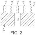
- Figure 2 shows a cross-section through a porous filter substrate 10 comprising a surface pore 12.
- Figure 2 shows an embodiment, featuring a porous surface washcoat layer 14 comprised of solid washcoat particles, the spaces between which particles define pores (interparticle pores). It can be seen that the washcoat layer 14 substantially covers the pore 12 of the porous structure and that a mean pore size of the interparticle pores 16 is less than the mean pore size 12 of the porous filter substrate 10.
- Figure 3 shows an apparatus 11 according to the invention comprising a vehicular positive ignition engine 13 and an exhaust system 15 therefor.
- Exhaust system 15 comprises a conduit 17 linking catalytic aftertreatment components, namely a Pd-Rh-based TWC coated onto an inert cordierite flowthrough substrate 18 disposed close to the exhaust manifold of the engine (the so-called close coupled position).
- Downstream of the close-coupled catalyst 18 in turn is a zoned CuCHA SCR catalyst coated onto a cordierite wall-flow filter 20 having a total length and comprising inlet channels coated to a length of one third of the total length measured from an upstream or inlet end of the wall-flow filter with a washcoat loading of 2.8 gin -3 (170.9 g/1), which coating defining a first zone 22.
- the outlet channels are coated with a CuCHA SCR catalyst coated on two thirds of the total length of the wall-flow filter measured from the downstream or outlet end of the wall-flow filter with a washcoat loading of 1.0 gin -3 (61.0 g/1), which coating defining a second zone 24.
- Engine management means (not shown) is run intermittently rich, i.e. in "rich spike"-type mode, thereby to contact the upstream TWC with enriched exhaust gas and to generate ammonia and other reformed nitrogenous reductant species in situ and to promote NOx conversion on the downstream SCR catalyst.
- Example 2 is relevant to a NOx absorber catalyst embodiment, wherein the first upstream zone has a higher platinum group metal loading than the second downstream zone with improvements in both hydrocarbon light off temperature, which is also an important aspect of NOx absorber catalyst activity, and backpressure.
- the washcoat loadings quoted in the Examples were obtained using the method disclosed in WO 2011/080525 .
- Two cordierite wall-flow filters of dimensions 4.66 x 5.5 inches (11.8 x 14.0 cm), 300 cells per square inch (46.5 cells cm -2 ), wall thickness 12 thousandths of an inch (0.3 mm) and having a mean pore size of 20 ⁇ m and a porosity of 65% were each coated with a TWC composition in a different configuration from the other.
- the TWC composition was milled to a d90 ⁇ 17 ⁇ m) so that the coating when applied would be expected preferentially to locate more at the surface of a wallflow filter wall ("on-wall").
- a first filter (referred to in Table 1 as having a "Homogeneous" washcoat loading) was coated in channels intended for the inlet side of the filter with a TWC washcoat zone extending for a targeted 33.3% of the total length of the filter substrate measured from the open channel ends with a washcoat comprising a precious metal loading of 85 g/ft 3 (80Pd:5Rh) and at a washcoat loading of 2.4 g/in 3 (146.5 g/1).
- the outlet channels were coated to a length of 66.6% of the total length of the filter substrate measured from the open channel ends with a washcoat comprising a precious metal loading of 18 g/ft 3 (0.64 g/l) (16Pd:2Rh) at a washcoat loading also of 2.4 g/in 3 (146.5 g/1).
- X-ray imaging was used to ensure that an overlap occurred in the longitudinal plane between the inlet channel zone and the outlet channel zone. So, the washcoat loading was homogeneous between the first and second zones, but the platinum group metal loading in the first zone > second zone.
- a second filter (referred to in Table 1 as having a "Zoned" washcoat loading) was coated in the inlet channels with a TWC washcoat zone extending for a targeted 33.33% of the total length of the filter substrate measured from the open channel ends with a washcoat comprising a precious metal loading of 85 g/ft 3 (3.00 g/l) (80Pd:5Rh) and at a washcoat loading of 2.8 g/in 3 (170.9 g/1).
- the outlet channels were coated to a length of 66.66% of the total length of the filter substrate measured from the open channel ends with a washcoat comprising a precious metal loading of 18 g/ft 3 (0.64 g/l) (16Pd:2Rh) at a washcoat loading of 1.0 g/in 3 (61.0 g/1).
- X-ray imaging was used to ensure that an overlap occurred in the longitudinal plane between the inlet channel zone and the outlet channel zone. So, both the washcoat loading and the platinum group metal loading in the first zone > second zone. That is, the second filter is according to claim 1, feature (ii).
- the total precious metal content of the first and second filters was identical.
- Each filter was hydrothermally oven-aged at 1100°C for 4 hours and installed in a close-coupled position on a Euro 5 passenger car with a 2.0L direct injection gasoline engine.
- Each filter was evaluated over a minimum of three MVEG-B drive cycles, measuring the reduction in particle number emissions relative to a reference catalyst.
- the reference catalyst was a TWC coated homogeneously onto a 600 cells per square inch (93.0 cells cm -2 ) cordierite flowthrough substrate monolith having the same dimensions as the first and second filters and at a washcoat loading of 3gin -3 (183.1 g/1) and a precious metal loading of 33gft -3 (1.17 g/1) (30Pd:3Rh).
- the backpressure differential was determined between sensors mounted upstream and downstream of the filter (or reference catalyst).
- the Euro 5/6 implementing legislation introduces a new PM mass emission measurement method developed by the UN/ECE Particulate Measurement Programme (PMP) which adjusts the PM mass emission limits to account for differences in results using old and the new methods.
- PMP Particulate Measurement Programme
- the Euro 5/6 legislation also introduces a particle number emission limit (PMP method), in addition to the mass-based limits.
- Two cordierite wall-flow filters of dimensions 4.66 x 4.5 inches (11.8 x 11.4 cm), 300 cells per square inch (46.5 cells cm -2 ), wall thickness 12 thousandths of an inch (0.3 mm), mean pore size of 20 ⁇ m and a porosity of 65% were each coated with a TWC composition in a different configuration from the other.
- the TWC composition was milled to a d90 ⁇ 17 ⁇ m) so that the coating when applied would be expected preferentially to locate more at the surface of a wallflow filter wall ("on-wall").
- a third filter (referred to in Table 2 as having a "Homogeneous" platinum group metal loading (Comparative Example)) was coated in channels intended for the inlet side of the filter and outlet side of the filter with a TWC washcoat zone extending for a targeted 50% of the total length of the filter substrate measured from the open channel ends with a washcoat comprising a precious metal loading of 60gft -3 (2.1 g/1) (57Pd:3Rh) and at a washcoat loading of 2.4 g/in 3 (146.5 g/1).
- a fourth filter (referred to in Table 2 as having a "Zoned" PGM loading) was coated in channels intended for the inlet side of the filter with a TWC washcoat zone extending for a targeted 50% of the total length of the filter substrate measured from the open channel ends with a washcoat comprising 100g/ft -3 (3.53 g/1) precious metal (97Pd:3Rh) at a washcoat loading of 2.4 g/in 3 (146.5 g/1); and the outlet channels were coated with a TWC washcoat zone extending for a targeted 50% of the total length of the filter substrate measured from the open channel ends with a washcoat comprising 20 g/ft -3 (0.71 g/1) precious metal (17Pd:3Rh), also at a washcoat loading of 2.4 g/in 3 (146.5 g/1).
- the total precious metal content of the third and fourth filters was identical.
- Each filter was hydrothermally oven-aged at 1100°C for 4 hours and installed in a close-coupled position on a Euro 5 passenger car with a 1.4L direct injection gasoline engine. Each filter was evaluated over a minimum of three MVEG-B drive cycles, measuring the reduction in particle number emissions relative to a reference catalyst. Peak backpressure (BP) was also evaluated in the same way as described in Example 1.
- Hydrocarbon light-off temperature (the temperature at which the catalyst catalyses the conversion of hydrocarbons in the feed gas at 50% efficiency or greater) was evaluated on a separate engine mounted in a laboratory test cell. This engine was a 2.0 litre turbo charged direct injection gasoline engine. The exhaust gas temperature was carefully regulated and increased from 250-450°C over a given period of time through the use of a combination of a temperature heat sink and increasing throttle position, during which time the conversion efficiency of the catalyst was measured and reported.
- Two cordierite wall-flow filters of dimensions 4.66 x 5.5 inches (11.8 x 14.0 cm), 300 cells per square inch (46.5 cells cm -2 ), wall thickness 12 thousandths of an inch (0.3 mm) and having a mean pore size of 20 ⁇ m and a porosity of 65% were each coated with a TWC composition in a different configuration from the other.
- a first, reference filter was zone coated homogeneously to a length of 50% of total filter length from the inlet end and to a length of 50% of total filter length from the outlet end with the same three-way catalyst washcoat at 40g/ft 3 (1.41 g/1) total platinum group metals and to a total of 1.6 g/in 3 (97.6 g/1) washcoat loading.
- a second filter, according to the invention, was zone coated with an identical three-way catalyst washcoat to that which was used in the reference Example to a length of 50% of total length of the filter from the inlet end.
- the outlet end zone was left bare of any washcoat.
- a total platinum group metal loading in the first, inlet zone was 80g/ft -3 (2.83 g/1) at a washcoat loading of 2.4 g/in -3 (146.5 g/1), i.e. the platinum group metal loading was identical between the reference Example and the filter according to the present invention.
- the coated filters were each hydrothermally oven aged in 10% water/air for 5 hours at 950°C.
- Cold flow back pressure of each part was measured at room temperature using a SuperFlow® backpressure laboratory test apparatus drawing air at room temperature and pressure.
- Table 3 Presenting cold flow back pressure (mBar or x100 Pa) vs.
Landscapes
- Engineering & Computer Science (AREA)
- Chemical & Material Sciences (AREA)
- Chemical Kinetics & Catalysis (AREA)
- Combustion & Propulsion (AREA)
- General Engineering & Computer Science (AREA)
- Mechanical Engineering (AREA)
- Health & Medical Sciences (AREA)
- Materials Engineering (AREA)
- Oil, Petroleum & Natural Gas (AREA)
- Biomedical Technology (AREA)
- Environmental & Geological Engineering (AREA)
- Analytical Chemistry (AREA)
- General Chemical & Material Sciences (AREA)
- Organic Chemistry (AREA)
- Toxicology (AREA)
- Crystallography & Structural Chemistry (AREA)
- Ceramic Engineering (AREA)
- Exhaust Gas After Treatment (AREA)
- Catalysts (AREA)
- Processes For Solid Components From Exhaust (AREA)
- Combined Controls Of Internal Combustion Engines (AREA)
- Exhaust Gas Treatment By Means Of Catalyst (AREA)
Applications Claiming Priority (3)
| Application Number | Priority Date | Filing Date | Title |
|---|---|---|---|
| US201361815443P | 2013-04-24 | 2013-04-24 | |
| GB1307421.6A GB2513364B (en) | 2013-04-24 | 2013-04-24 | Positive ignition engine and exhaust system comprising catalysed zone-coated filter substrate |
| PCT/GB2014/051254 WO2014174277A1 (en) | 2013-04-24 | 2014-04-23 | Positive ignition engine and exhaust system comprising catalysed zone-coated filter substrate |
Publications (2)
| Publication Number | Publication Date |
|---|---|
| EP2989303A1 EP2989303A1 (en) | 2016-03-02 |
| EP2989303B1 true EP2989303B1 (en) | 2019-09-04 |
Family
ID=48579596
Family Applications (1)
| Application Number | Title | Priority Date | Filing Date |
|---|---|---|---|
| EP14719824.6A Active EP2989303B1 (en) | 2013-04-24 | 2014-04-23 | Positive ignition engine and exhaust system comprising catalysed zone-coated filter substrate |
Country Status (10)
| Country | Link |
|---|---|
| US (2) | US9347349B2 (enExample) |
| EP (1) | EP2989303B1 (enExample) |
| JP (3) | JP6389871B2 (enExample) |
| KR (2) | KR102125794B1 (enExample) |
| CN (3) | CN105264188B (enExample) |
| BR (1) | BR112015026878B1 (enExample) |
| DE (2) | DE102014105739A1 (enExample) |
| GB (3) | GB2513364B (enExample) |
| RU (2) | RU2668191C2 (enExample) |
| WO (1) | WO2014174277A1 (enExample) |
Families Citing this family (65)
| Publication number | Priority date | Publication date | Assignee | Title |
|---|---|---|---|---|
| US8512657B2 (en) * | 2009-02-26 | 2013-08-20 | Johnson Matthey Public Limited Company | Method and system using a filter for treating exhaust gas having particulate matter |
| GB201207313D0 (en) | 2012-04-24 | 2012-06-13 | Johnson Matthey Plc | Filter substrate comprising three-way catalyst |
| GB2513364B (en) | 2013-04-24 | 2019-06-19 | Johnson Matthey Plc | Positive ignition engine and exhaust system comprising catalysed zone-coated filter substrate |
| GB2512648B (en) | 2013-04-05 | 2018-06-20 | Johnson Matthey Plc | Filter substrate comprising three-way catalyst |
| JP2016527427A (ja) * | 2013-05-31 | 2016-09-08 | ジョンソン、マッセイ、パブリック、リミテッド、カンパニーJohnson Matthey Public Limited Company | 排ガスを処理するための触媒化フィルタ |
| US9687786B2 (en) * | 2013-05-31 | 2017-06-27 | Johnson Matthey Public Limited Company | Catalyzed filter for treating exhaust gas |
| GB2556231B (en) * | 2013-07-30 | 2019-04-03 | Johnson Matthey Plc | Ammonia slip catalyst |
| EP2905074B1 (de) * | 2014-02-06 | 2019-04-24 | Heraeus Deutschland GmbH & Co. KG | Katalytisch wirksame Zusammensetzung für einen Mehrschichtkatalysator zur Abgasnachbehandlung von Verbrennungsabgasen |
| EP3174620A4 (en) * | 2014-07-29 | 2018-04-25 | SDCmaterials, Inc. | Three way catalytic converter using hybrid catalytic particles |
| WO2016019067A1 (en) * | 2014-07-29 | 2016-02-04 | SDCmaterials, Inc. | Zone coated catalytic substrates with passive nox adsorption zones |
| JP6655060B2 (ja) * | 2015-02-17 | 2020-02-26 | 株式会社キャタラー | 排ガス浄化用触媒 |
| JP6472677B2 (ja) * | 2015-02-17 | 2019-02-20 | 株式会社キャタラー | 排ガス浄化用触媒 |
| CA2972861C (en) * | 2015-03-26 | 2023-03-28 | Basf Corporation | Exhaust gas treatment system |
| GB2538296A (en) * | 2015-05-14 | 2016-11-16 | Gm Global Tech Operations Llc | Method of operating an aftertreatment device in an automotive system |
| CN107849962B (zh) * | 2015-05-19 | 2020-10-30 | 巴斯夫公司 | 用于钝化选择性催化还原的催化烟灰过滤器及其制备方法 |
| EP3307997B1 (en) * | 2015-06-12 | 2020-03-18 | BASF Corporation | Exhaust gas treatment system |
| DE102015225579A1 (de) * | 2015-12-17 | 2017-06-22 | Umicore Ag & Co. Kg | Verfahren zur Verhinderung der Kontamination eines SCR-Katalysators mit Platin |
| GB2546745A (en) * | 2016-01-26 | 2017-08-02 | Johnson Matthey Plc | Exhaust system |
| JP6987083B2 (ja) * | 2016-06-10 | 2021-12-22 | ジョンソン、マッセイ、パブリック、リミテッド、カンパニーJohnson Matthey Public Limited Company | NOx吸着体触媒 |
| GB2560926A (en) * | 2017-03-28 | 2018-10-03 | Johnson Matthey Plc | NOx adsorber catalyst |
| EP3257571A1 (de) | 2016-06-13 | 2017-12-20 | Umicore AG & Co. KG | Partikelfilter mit integrierter nox-speicher- und h2s-sperrfunktion |
| CN109475804A (zh) * | 2016-07-22 | 2019-03-15 | 庄信万丰股份有限公司 | 用于过滤器基质的废气催化剂和催化剂粘合剂 |
| US20190224649A1 (en) | 2016-07-29 | 2019-07-25 | Umicore Ag & Co. Kg | Catalyst for reduction of nitrogen oxides |
| GB2554656A (en) * | 2016-09-30 | 2018-04-11 | Jaguar Land Rover Ltd | Exhaust gas treatment apparatus |
| JP2018143955A (ja) * | 2017-03-06 | 2018-09-20 | イビデン株式会社 | ハニカムフィルタ |
| GB2562161A (en) * | 2017-03-20 | 2018-11-07 | Johnson Matthey Plc | Rear on-wall design SCRF |
| US11105234B2 (en) * | 2017-08-11 | 2021-08-31 | Ford Global Technologies, Llc | Particulate filters |
| US11141717B2 (en) | 2017-08-31 | 2021-10-12 | Umicore Ag & Co. Kg | Palladium/zeolite-based passive nitrogen oxide adsorber catalyst for purifying exhaust gas |
| EP3450016A1 (de) | 2017-08-31 | 2019-03-06 | Umicore Ag & Co. Kg | Palladium-zeolith-basierter passiver stickoxid-adsorber-katalysator zur abgasreinigung |
| JP2020531241A (ja) | 2017-08-31 | 2020-11-05 | ユミコア・アクチエンゲゼルシャフト・ウント・コムパニー・コマンディットゲゼルシャフトUmicore AG & Co.KG | 排気ガスを浄化するための受動的窒素酸化物吸着剤としてのパラジウム/白金/ゼオライト系触媒の使用 |
| EP3450015A1 (de) | 2017-08-31 | 2019-03-06 | Umicore Ag & Co. Kg | Palladium-zeolith-basierter passiver stickoxid-adsorber-katalysator zur abgasreinigung |
| EP3449999A1 (de) | 2017-08-31 | 2019-03-06 | Umicore Ag & Co. Kg | Passiver stickoxid-adsorber |
| IT201700101864A1 (it) * | 2017-09-12 | 2019-03-12 | Fca Italy Spa | Filtro di particolato per un motore a combustione interna a benzina |
| WO2019055040A1 (en) * | 2017-09-18 | 2019-03-21 | Ford Global Technologies, Llc | CATALYST FOR CONTROLLING THE EMISSIONS OF MOTOR VEHICLES |
| EP3459617B1 (de) | 2017-09-22 | 2020-01-29 | Umicore Ag & Co. Kg | Partikelfilter mit integrierten katalytischen funktionen |
| WO2019067299A1 (en) * | 2017-09-27 | 2019-04-04 | Johnson Matthey Public Limited Company | SINGLE LAYER CATALYST WITH LOW IMPREGNATION LOAD FOR FUEL EXHAUST GAS CLEANING APPLICATIONS |
| EP3501648B1 (de) | 2017-12-19 | 2023-10-04 | Umicore Ag & Co. Kg | Katalytisch aktives partikelfilter |
| EP3505245B1 (de) | 2017-12-19 | 2019-10-23 | Umicore Ag & Co. Kg | Katalytisch aktives partikelfilter |
| EP3505246B1 (de) * | 2017-12-19 | 2019-10-23 | Umicore Ag & Co. Kg | Katalytisch aktives partikelfilter |
| EP3735310A1 (de) | 2018-01-05 | 2020-11-11 | Umicore Ag & Co. Kg | Passiver stickoxid-adsorber |
| CN112384292B (zh) * | 2018-07-24 | 2023-12-29 | 巴斯夫公司 | 用于处理柴油发动机废气的scr催化剂 |
| EP3613503A1 (en) | 2018-08-22 | 2020-02-26 | Umicore Ag & Co. Kg | Passive nitrogen oxide adsorber |
| JP6781742B2 (ja) * | 2018-09-12 | 2020-11-04 | イビデン株式会社 | ハニカム構造体 |
| US11439952B2 (en) | 2018-11-16 | 2022-09-13 | Umicore Ag & Co. Kg | Low temperature nitrogen oxide adsorber |
| EP3903932A4 (en) * | 2018-12-28 | 2022-02-16 | Umicore Shokubai Japan Co., Ltd. | EXHAUST GAS OXIDATION CATALYST, METHOD FOR PRODUCING IT AND METHOD FOR EXHAUST GAS PURIFICATION USING THE SAME |
| CN113272057A (zh) | 2019-01-08 | 2021-08-17 | 优美科股份公司及两合公司 | 具有氧化催化活性功能的被动氮氧化物吸附器 |
| WO2020163123A1 (en) * | 2019-02-08 | 2020-08-13 | Corning Incorporated | Zone-coated ceramic particulate partial filter |
| WO2020172489A1 (en) * | 2019-02-21 | 2020-08-27 | Johnson Matthey Public Limited Company | A catalytic article and the use thereof for the treatment of an exhaust gas |
| GB2583581B (en) * | 2019-03-29 | 2022-06-15 | Johnson Matthey Plc | A catalyst article and the use thereof for filtering fine particles |
| WO2020200398A1 (de) | 2019-03-29 | 2020-10-08 | Umicore Ag & Co. Kg | Katalytisch aktives partikelfilter |
| EP3986611A1 (en) * | 2019-06-20 | 2022-04-27 | BASF Corporation | Automotive 3-way catalyst system containing a tail pipe catalyst |
| CN117085675B (zh) | 2019-06-26 | 2024-12-31 | 庄信万丰股份有限公司 | 用于压缩点火内燃机的复合分区氧化催化剂 |
| WO2021021426A1 (en) * | 2019-07-31 | 2021-02-04 | Cummins Emission Solutions Inc. | Systems and methods for recovering catalyst performance |
| GB2605036B (en) | 2019-10-16 | 2024-09-11 | Johnson Matthey Plc | Compression ignition internal combustion engine comprising an exhaust system comprising a composite, zoned oxidation catalyst |
| US12318760B2 (en) | 2019-10-16 | 2025-06-03 | Johnson Matthey Public Limited Company | Composite, zone-coated, dual-use ammonia (AMOX) and nitric oxide oxidation catalyst |
| EP3824988B1 (en) | 2019-11-20 | 2025-03-05 | Umicore AG & Co. KG | Catalyst for reducing nitrogen oxides |
| EP4079401B1 (en) * | 2019-12-18 | 2024-03-27 | Mitsui Mining & Smelting Co., Ltd. | Exhaust gas purification catalyst |
| WO2022071926A1 (en) * | 2020-09-29 | 2022-04-07 | Johnson Matthey Public Limited Company | A catalyst article and the use thereof for filtering fine particles |
| WO2022142836A1 (zh) * | 2020-12-28 | 2022-07-07 | 中化学科学技术研究有限公司 | 一种催化组合物、催化剂层、催化装置和气体处理系统 |
| DE102021105722A1 (de) | 2021-03-10 | 2022-09-15 | Volkswagen Aktiengesellschaft | Brennkraftmaschine mit Katalysatoreinrichtung mit unterschiedlicher spezifischer Menge des Katalysatormaterials |
| GB2608882B (en) * | 2021-05-12 | 2023-04-26 | Johnson Matthey Plc | Apparatus and methods for dry powder coating a filter |
| CN113274879A (zh) * | 2021-07-22 | 2021-08-20 | 山东艾泰克环保科技股份有限公司 | 一种气体机用尾气后处理系统及其制备方法和应用 |
| EP4279821A1 (en) * | 2022-05-18 | 2023-11-22 | B/E Aerospace, Inc. | Filter for an aircraft oven |
| CN119907714A (zh) * | 2022-07-05 | 2025-04-29 | 巴斯夫移动排放催化剂有限公司 | 用于发动机排气处理的催化制品 |
| CN119303438A (zh) * | 2023-07-14 | 2025-01-14 | 中国石油化工股份有限公司 | 催化剂生产废气的处理方法 |
Family Cites Families (88)
| Publication number | Priority date | Publication date | Assignee | Title |
|---|---|---|---|---|
| DE10020170C1 (de) | 2000-04-25 | 2001-09-06 | Emitec Emissionstechnologie | Verfahren zum Entfernen von Rußpartikeln aus einem Abgas und zugehöriges Auffangelement |
| US5057483A (en) | 1990-02-22 | 1991-10-15 | Engelhard Corporation | Catalyst composition containing segregated platinum and rhodium components |
| KR960002348B1 (ko) | 1991-10-03 | 1996-02-16 | 도요다 지도오샤 가부시끼가이샤 | 내연기관의 배기정화장치 |
| JP3387290B2 (ja) | 1995-10-02 | 2003-03-17 | トヨタ自動車株式会社 | 排ガス浄化用フィルター |
| US6423293B1 (en) | 1996-09-06 | 2002-07-23 | Ford Global Technologies, Inc. | Oxygen storage material for automotive catalysts and process of using |
| US5898014A (en) | 1996-09-27 | 1999-04-27 | Engelhard Corporation | Catalyst composition containing oxygen storage components |
| GB9805815D0 (en) | 1998-03-19 | 1998-05-13 | Johnson Matthey Plc | Manufacturing process |
| FI107828B (fi) | 1999-05-18 | 2001-10-15 | Kemira Metalkat Oy | Dieselmoottoreiden pakokaasujen puhdistusjärjestelmä ja menetelmä dieselmoottoreiden pakokaasujen puhdistamiseksi |
| US6306335B1 (en) | 1999-08-27 | 2001-10-23 | The Dow Chemical Company | Mullite bodies and methods of forming mullite bodies |
| JP2001221038A (ja) | 1999-12-13 | 2001-08-17 | Ford Global Technol Inc | 消音形排気コンバーター |
| US6846466B2 (en) | 2000-03-22 | 2005-01-25 | Cataler Corporation | Catalyst for purifying an exhaust gas |
| US20030126133A1 (en) | 2001-12-27 | 2003-07-03 | Slamdunk Networks, Inc. | Database replication using application program event playback |
| JP3528839B2 (ja) | 2002-05-15 | 2004-05-24 | トヨタ自動車株式会社 | パティキュレート酸化材及び酸化触媒 |
| US6946013B2 (en) * | 2002-10-28 | 2005-09-20 | Geo2 Technologies, Inc. | Ceramic exhaust filter |
| CN1431389A (zh) * | 2003-02-17 | 2003-07-23 | 清华大学 | 单通道径向圆筒式柴油车尾气微粒过滤装置 |
| JP4355506B2 (ja) | 2003-03-28 | 2009-11-04 | 日本碍子株式会社 | 触媒担持フィルタ及びこれを用いた排ガス浄化システム |
| JPWO2004106702A1 (ja) * | 2003-05-06 | 2006-07-20 | イビデン株式会社 | ハニカム構造体 |
| US7229597B2 (en) | 2003-08-05 | 2007-06-12 | Basfd Catalysts Llc | Catalyzed SCR filter and emission treatment system |
| CN2649783Y (zh) * | 2003-10-15 | 2004-10-20 | 北京科洛德铨都科技有限公司 | 柴油发动机尾气净化器 |
| JP4239864B2 (ja) | 2004-03-19 | 2009-03-18 | トヨタ自動車株式会社 | ディーゼル排ガス浄化装置 |
| WO2009100097A2 (en) | 2008-02-05 | 2009-08-13 | Basf Catalysts Llc | Gasoline engine emissions treatment systems having particulate traps |
| DE102004040548A1 (de) | 2004-08-21 | 2006-02-23 | Umicore Ag & Co. Kg | Verfahren zum Beschichten eines Wandflußfilters mit feinteiligen Feststoffen und damit erhaltenes Partikelfilter und seine Verwendung |
| US7481983B2 (en) * | 2004-08-23 | 2009-01-27 | Basf Catalysts Llc | Zone coated catalyst to simultaneously reduce NOx and unreacted ammonia |
| US7722829B2 (en) | 2004-09-14 | 2010-05-25 | Basf Catalysts Llc | Pressure-balanced, catalyzed soot filter |
| GB2406803A (en) | 2004-11-23 | 2005-04-13 | Johnson Matthey Plc | Exhaust system comprising exotherm-generating catalyst |
| US7389638B2 (en) | 2005-07-12 | 2008-06-24 | Exxonmobil Research And Engineering Company | Sulfur oxide/nitrogen oxide trap system and method for the protection of nitrogen oxide storage reduction catalyst from sulfur poisoning |
| US7678347B2 (en) | 2005-07-15 | 2010-03-16 | Basf Catalysts Llc | High phosphorous poisoning resistant catalysts for treating automobile exhaust |
| US8119075B2 (en) | 2005-11-10 | 2012-02-21 | Basf Corporation | Diesel particulate filters having ultra-thin catalyzed oxidation coatings |
| US7862640B2 (en) | 2006-03-21 | 2011-01-04 | Donaldson Company, Inc. | Low temperature diesel particulate matter reduction system |
| US7576031B2 (en) | 2006-06-09 | 2009-08-18 | Basf Catalysts Llc | Pt-Pd diesel oxidation catalyst with CO/HC light-off and HC storage function |
| WO2008011146A1 (en) * | 2006-07-21 | 2008-01-24 | Dow Global Technologies Inc. | Improved zone catalyzed soot filter |
| RU2438777C2 (ru) * | 2006-08-19 | 2012-01-10 | Умикоре Аг Унг Ко. Кг | Фильтр твердых частиц выхлопных газов дизельного двигателя с каталитическим покрытием, способ его изготовления и его применение |
| US20080053070A1 (en) | 2006-09-01 | 2008-03-06 | Andrew Hatton | Apparatus and method for regenerating a particulate filter with a non-uniformly loaded oxidation catalyst |
| US7709414B2 (en) | 2006-11-27 | 2010-05-04 | Nanostellar, Inc. | Engine exhaust catalysts containing palladium-gold |
| EP1961933B1 (de) * | 2007-02-23 | 2010-04-14 | Umicore AG & Co. KG | Katalytisch aktiviertes Dieselpartikelfilter mit Ammoniak-Sperrwirkung |
| US7998423B2 (en) * | 2007-02-27 | 2011-08-16 | Basf Corporation | SCR on low thermal mass filter substrates |
| BRPI0808091A2 (pt) * | 2007-02-27 | 2014-07-15 | Basf Catalysts Llc | Catalisador, sistema de tratamento de gás de exaustão, processo para a redução de óxidos de nitrogênio, e, artigo de catalisador. |
| US20100290963A1 (en) | 2007-04-26 | 2010-11-18 | Johnson Matthey Public Limited Company | Transition metal / zeolite scr catalysts |
| JP2009057922A (ja) | 2007-08-31 | 2009-03-19 | Honda Motor Co Ltd | 排ガス浄化装置 |
| DE102007046158B4 (de) | 2007-09-27 | 2014-02-13 | Umicore Ag & Co. Kg | Verwendung eines katalytisch aktiven Partikelfilters zur Entfernung von Partikeln aus dem Abgas von mit überwiegend stöchiometrischem Luft/Kraftstoff-Gemisch betriebenen Verbrennungsmotoren |
| EP2042225B2 (de) | 2007-09-28 | 2017-07-12 | Umicore AG & Co. KG | Entfernung von Partikeln aus dem Abgas von mit überwiegend stöchiometrischem Luft/Kraftstoff-Gemisch betriebenen Verbrennungsmotoren |
| EP2065575B1 (en) * | 2007-11-29 | 2012-08-15 | Corning Incorporated | Wall-flow honeycomb filter having high-storage capacity and low backpressure |
| US9993771B2 (en) * | 2007-12-12 | 2018-06-12 | Basf Corporation | Emission treatment catalysts, systems and methods |
| US8114354B2 (en) | 2007-12-18 | 2012-02-14 | Basf Corporation | Catalyzed soot filter manufacture and systems |
| US20090173063A1 (en) * | 2008-01-07 | 2009-07-09 | Boorse R Samuel | Mitigation of Particulates and NOx in Engine Exhaust |
| FR2928176B1 (fr) | 2008-02-29 | 2016-12-23 | Faurecia Systemes D'echappement | Procede de regeneration d'un filtre a particules pour moteur a essence et ensemble d'echappement associe |
| US8475752B2 (en) | 2008-06-27 | 2013-07-02 | Basf Corporation | NOx adsorber catalyst with superior low temperature performance |
| GB0812544D0 (en) * | 2008-07-09 | 2008-08-13 | Johnson Matthey Plc | Exhaust system for a lean burn IC engine |
| US20100077727A1 (en) | 2008-09-29 | 2010-04-01 | Southward Barry W L | Continuous diesel soot control with minimal back pressure penatly using conventional flow substrates and active direct soot oxidation catalyst disposed thereon |
| US8343448B2 (en) | 2008-09-30 | 2013-01-01 | Ford Global Technologies, Llc | System for reducing NOx in exhaust |
| JP5528040B2 (ja) | 2008-10-03 | 2014-06-25 | Dowaエレクトロニクス株式会社 | 排ガス浄化触媒用複合酸化物とその製造方法および排ガス浄化触媒用塗料とディーゼル排ガス浄化用フィルタ |
| CN102762279B (zh) | 2008-11-26 | 2016-03-02 | 康宁股份有限公司 | 涂覆的颗粒过滤器和方法 |
| US8512657B2 (en) * | 2009-02-26 | 2013-08-20 | Johnson Matthey Public Limited Company | Method and system using a filter for treating exhaust gas having particulate matter |
| GB0903262D0 (en) * | 2009-02-26 | 2009-04-08 | Johnson Matthey Plc | Filter |
| US8637426B2 (en) * | 2009-04-08 | 2014-01-28 | Basf Corporation | Zoned catalysts for diesel applications |
| JP2010269205A (ja) * | 2009-05-19 | 2010-12-02 | Toyota Motor Corp | 排ガス浄化用触媒 |
| US8758695B2 (en) * | 2009-08-05 | 2014-06-24 | Basf Se | Treatment system for gasoline engine exhaust gas |
| EP2322773B1 (de) * | 2009-10-28 | 2016-08-17 | Umicore AG & Co. KG | Verfahren zur Reinigung von Verbrennungsmotorenabgasen |
| GB0922195D0 (en) | 2009-12-21 | 2010-02-03 | Johnson Matthey Plc | Improvements in NOx traps |
| EP2516044B1 (en) * | 2009-12-24 | 2018-04-25 | Johnson Matthey PLC | Exhaust system for a vehicular positive ignition internal combustion engine |
| GB201000019D0 (en) | 2010-01-04 | 2010-02-17 | Johnson Matthey Plc | Coating a monolith substrate with catalyst component |
| JP5548470B2 (ja) * | 2010-02-16 | 2014-07-16 | 日本碍子株式会社 | ハニカム触媒体 |
| GB201003784D0 (en) | 2010-03-08 | 2010-04-21 | Johnson Matthey Plc | Improvement in control OPF emissions |
| US8815189B2 (en) * | 2010-04-19 | 2014-08-26 | Basf Corporation | Gasoline engine emissions treatment systems having particulate filters |
| US8293182B2 (en) * | 2010-05-05 | 2012-10-23 | Basf Corporation | Integrated SCR and AMOx catalyst systems |
| GB201100595D0 (en) | 2010-06-02 | 2011-03-02 | Johnson Matthey Plc | Filtration improvements |
| JP5973457B2 (ja) | 2010-11-16 | 2016-08-23 | ロディア オペレーションズRhodia Operations | アルミナ触媒担体 |
| US8323599B2 (en) | 2010-11-22 | 2012-12-04 | Umicore Ag & Co. Kg | Three-way catalyst having an upstream multi-layer catalyst |
| DE102010055147A1 (de) | 2010-12-18 | 2012-06-21 | Volkswagen Ag | Vier-Wege-Katalysator, seine Verwendung sowie Fahrzeug mit einem solchen |
| DE102011050788A1 (de) | 2011-06-01 | 2012-12-06 | Ford Global Technologies, Llc. | Abgasnachbehandlungsvorrichtung und -verfahren für einen Ottomotor |
| GB2492175B (en) * | 2011-06-21 | 2018-06-27 | Johnson Matthey Plc | Exhaust system for internal combustion engine comprising catalysed filter substrate |
| US8789356B2 (en) * | 2011-07-28 | 2014-07-29 | Johnson Matthey Public Limited Company | Zoned catalytic filters for treatment of exhaust gas |
| WO2013035159A1 (ja) * | 2011-09-06 | 2013-03-14 | トヨタ自動車株式会社 | 内燃機関の排気浄化装置 |
| JP5938819B2 (ja) | 2011-10-06 | 2016-06-22 | ジョンソン、マッセイ、パブリック、リミテッド、カンパニーJohnson Matthey Public Limited Company | 排気ガス処理用酸化触媒 |
| GB201200781D0 (en) | 2011-12-12 | 2012-02-29 | Johnson Matthey Plc | Exhaust system for a lean-burn ic engine comprising a pgm component and a scr catalyst |
| GB2497597A (en) * | 2011-12-12 | 2013-06-19 | Johnson Matthey Plc | A Catalysed Substrate Monolith with Two Wash-Coats |
| GB201200784D0 (en) * | 2011-12-12 | 2012-02-29 | Johnson Matthey Plc | Exhaust system for a lean-burn internal combustion engine including SCR catalyst |
| GB201200783D0 (en) * | 2011-12-12 | 2012-02-29 | Johnson Matthey Plc | Substrate monolith comprising SCR catalyst |
| EP2650042B2 (en) | 2012-04-13 | 2020-09-02 | Umicore AG & Co. KG | Pollutant abatement system for gasoline vehicles |
| GB2513364B (en) | 2013-04-24 | 2019-06-19 | Johnson Matthey Plc | Positive ignition engine and exhaust system comprising catalysed zone-coated filter substrate |
| GB201207313D0 (en) * | 2012-04-24 | 2012-06-13 | Johnson Matthey Plc | Filter substrate comprising three-way catalyst |
| BR112015011998A2 (pt) * | 2012-11-30 | 2017-07-11 | Johnson Matthey Plc | artigo catalisador, método e sistema para o tratamento de um gás de emissão, e, método para preparar um artigo catalisador |
| GB201302686D0 (en) * | 2013-02-15 | 2013-04-03 | Johnson Matthey Plc | Filter comprising three-way catalyst |
| WO2014160289A1 (en) * | 2013-03-14 | 2014-10-02 | Basf Corporation | Selective catalytic reduction catalyst system |
| US9333490B2 (en) * | 2013-03-14 | 2016-05-10 | Basf Corporation | Zoned catalyst for diesel applications |
| BR112015022045B1 (pt) * | 2013-03-14 | 2021-12-21 | Basf Corporation | Sistema híbrido de catalisador de redução catalítica seletiva |
| WO2014141200A1 (en) * | 2013-03-15 | 2014-09-18 | Johnson Matthey Public Limited Company | Catalyst for treating exhaust gas |
| GB2512648B (en) | 2013-04-05 | 2018-06-20 | Johnson Matthey Plc | Filter substrate comprising three-way catalyst |
-
2013
- 2013-04-24 GB GB1307421.6A patent/GB2513364B/en active Active
-
2014
- 2014-04-23 GB GB2002234.9A patent/GB2578706B/en not_active Expired - Fee Related
- 2014-04-23 EP EP14719824.6A patent/EP2989303B1/en active Active
- 2014-04-23 DE DE102014105739.2A patent/DE102014105739A1/de not_active Ceased
- 2014-04-23 KR KR1020157033062A patent/KR102125794B1/ko not_active Expired - Fee Related
- 2014-04-23 KR KR1020157033060A patent/KR102125728B1/ko active Active
- 2014-04-23 JP JP2016509547A patent/JP6389871B2/ja not_active Expired - Fee Related
- 2014-04-23 WO PCT/GB2014/051254 patent/WO2014174277A1/en not_active Ceased
- 2014-04-23 CN CN201480032667.8A patent/CN105264188B/zh active Active
- 2014-04-23 JP JP2016509545A patent/JP6302047B2/ja active Active
- 2014-04-23 BR BR112015026878-1A patent/BR112015026878B1/pt not_active IP Right Cessation
- 2014-04-23 US US14/259,876 patent/US9347349B2/en active Active
- 2014-04-23 GB GB2002232.3A patent/GB2578704B/en not_active Expired - Fee Related
- 2014-04-23 DE DE102014105736.8A patent/DE102014105736A1/de not_active Ceased
- 2014-04-23 CN CN201810925441.0A patent/CN109012176A/zh active Pending
- 2014-04-23 RU RU2015150059A patent/RU2668191C2/ru active
- 2014-04-23 CN CN201480032664.4A patent/CN105283241B/zh not_active Expired - Fee Related
- 2014-04-23 RU RU2015150057A patent/RU2650992C2/ru active
- 2014-04-24 US US14/260,405 patent/US9366166B2/en not_active Expired - Fee Related
-
2018
- 2018-02-28 JP JP2018034474A patent/JP2018128020A/ja active Pending
Non-Patent Citations (1)
| Title |
|---|
| None * |
Also Published As
Similar Documents
| Publication | Publication Date | Title |
|---|---|---|
| EP2989303B1 (en) | Positive ignition engine and exhaust system comprising catalysed zone-coated filter substrate | |
| EP2401056B1 (en) | Filter for filtering particulate matter from exhaust gas emitted from a positive ignition engine | |
| US9415344B2 (en) | Method and system using a filter for treating exhaust gas having particulate matter | |
| EP2841184B1 (en) | Filter substrate comprising three-way catalyst | |
| EP2516044B1 (en) | Exhaust system for a vehicular positive ignition internal combustion engine | |
| JP2016524066A5 (enExample) | ||
| EP2988851B1 (en) | Positive ignition engine with filter substrate comprising zone-coated catalyst washcoat |
Legal Events
| Date | Code | Title | Description |
|---|---|---|---|
| PUAI | Public reference made under article 153(3) epc to a published international application that has entered the european phase |
Free format text: ORIGINAL CODE: 0009012 |
|
| 17P | Request for examination filed |
Effective date: 20151109 |
|
| AK | Designated contracting states |
Kind code of ref document: A1 Designated state(s): AL AT BE BG CH CY CZ DE DK EE ES FI FR GB GR HR HU IE IS IT LI LT LU LV MC MK MT NL NO PL PT RO RS SE SI SK SM TR |
|
| AX | Request for extension of the european patent |
Extension state: BA ME |
|
| DAX | Request for extension of the european patent (deleted) | ||
| STAA | Information on the status of an ep patent application or granted ep patent |
Free format text: STATUS: EXAMINATION IS IN PROGRESS |
|
| 17Q | First examination report despatched |
Effective date: 20170217 |
|
| GRAP | Despatch of communication of intention to grant a patent |
Free format text: ORIGINAL CODE: EPIDOSNIGR1 |
|
| STAA | Information on the status of an ep patent application or granted ep patent |
Free format text: STATUS: GRANT OF PATENT IS INTENDED |
|
| INTG | Intention to grant announced |
Effective date: 20190403 |
|
| GRAS | Grant fee paid |
Free format text: ORIGINAL CODE: EPIDOSNIGR3 |
|
| GRAA | (expected) grant |
Free format text: ORIGINAL CODE: 0009210 |
|
| STAA | Information on the status of an ep patent application or granted ep patent |
Free format text: STATUS: THE PATENT HAS BEEN GRANTED |
|
| AK | Designated contracting states |
Kind code of ref document: B1 Designated state(s): AL AT BE BG CH CY CZ DE DK EE ES FI FR GB GR HR HU IE IS IT LI LT LU LV MC MK MT NL NO PL PT RO RS SE SI SK SM TR |
|
| REG | Reference to a national code |
Ref country code: GB Ref legal event code: FG4D |
|
| REG | Reference to a national code |
Ref country code: CH Ref legal event code: EP |
|
| REG | Reference to a national code |
Ref country code: AT Ref legal event code: REF Ref document number: 1175637 Country of ref document: AT Kind code of ref document: T Effective date: 20190915 |
|
| REG | Reference to a national code |
Ref country code: DE Ref legal event code: R096 Ref document number: 602014052925 Country of ref document: DE |
|
| REG | Reference to a national code |
Ref country code: IE Ref legal event code: FG4D |
|
| REG | Reference to a national code |
Ref country code: NL Ref legal event code: MP Effective date: 20190904 |
|
| REG | Reference to a national code |
Ref country code: LT Ref legal event code: MG4D |
|
| PG25 | Lapsed in a contracting state [announced via postgrant information from national office to epo] |
Ref country code: FI Free format text: LAPSE BECAUSE OF FAILURE TO SUBMIT A TRANSLATION OF THE DESCRIPTION OR TO PAY THE FEE WITHIN THE PRESCRIBED TIME-LIMIT Effective date: 20190904 Ref country code: SE Free format text: LAPSE BECAUSE OF FAILURE TO SUBMIT A TRANSLATION OF THE DESCRIPTION OR TO PAY THE FEE WITHIN THE PRESCRIBED TIME-LIMIT Effective date: 20190904 Ref country code: BG Free format text: LAPSE BECAUSE OF FAILURE TO SUBMIT A TRANSLATION OF THE DESCRIPTION OR TO PAY THE FEE WITHIN THE PRESCRIBED TIME-LIMIT Effective date: 20191204 Ref country code: NO Free format text: LAPSE BECAUSE OF FAILURE TO SUBMIT A TRANSLATION OF THE DESCRIPTION OR TO PAY THE FEE WITHIN THE PRESCRIBED TIME-LIMIT Effective date: 20191204 Ref country code: LT Free format text: LAPSE BECAUSE OF FAILURE TO SUBMIT A TRANSLATION OF THE DESCRIPTION OR TO PAY THE FEE WITHIN THE PRESCRIBED TIME-LIMIT Effective date: 20190904 Ref country code: HR Free format text: LAPSE BECAUSE OF FAILURE TO SUBMIT A TRANSLATION OF THE DESCRIPTION OR TO PAY THE FEE WITHIN THE PRESCRIBED TIME-LIMIT Effective date: 20190904 |
|
| PG25 | Lapsed in a contracting state [announced via postgrant information from national office to epo] |
Ref country code: RS Free format text: LAPSE BECAUSE OF FAILURE TO SUBMIT A TRANSLATION OF THE DESCRIPTION OR TO PAY THE FEE WITHIN THE PRESCRIBED TIME-LIMIT Effective date: 20190904 Ref country code: LV Free format text: LAPSE BECAUSE OF FAILURE TO SUBMIT A TRANSLATION OF THE DESCRIPTION OR TO PAY THE FEE WITHIN THE PRESCRIBED TIME-LIMIT Effective date: 20190904 Ref country code: GR Free format text: LAPSE BECAUSE OF FAILURE TO SUBMIT A TRANSLATION OF THE DESCRIPTION OR TO PAY THE FEE WITHIN THE PRESCRIBED TIME-LIMIT Effective date: 20191205 Ref country code: AL Free format text: LAPSE BECAUSE OF FAILURE TO SUBMIT A TRANSLATION OF THE DESCRIPTION OR TO PAY THE FEE WITHIN THE PRESCRIBED TIME-LIMIT Effective date: 20190904 Ref country code: ES Free format text: LAPSE BECAUSE OF FAILURE TO SUBMIT A TRANSLATION OF THE DESCRIPTION OR TO PAY THE FEE WITHIN THE PRESCRIBED TIME-LIMIT Effective date: 20190904 |
|
| REG | Reference to a national code |
Ref country code: AT Ref legal event code: MK05 Ref document number: 1175637 Country of ref document: AT Kind code of ref document: T Effective date: 20190904 |
|
| PG25 | Lapsed in a contracting state [announced via postgrant information from national office to epo] |
Ref country code: IT Free format text: LAPSE BECAUSE OF FAILURE TO SUBMIT A TRANSLATION OF THE DESCRIPTION OR TO PAY THE FEE WITHIN THE PRESCRIBED TIME-LIMIT Effective date: 20190904 Ref country code: EE Free format text: LAPSE BECAUSE OF FAILURE TO SUBMIT A TRANSLATION OF THE DESCRIPTION OR TO PAY THE FEE WITHIN THE PRESCRIBED TIME-LIMIT Effective date: 20190904 Ref country code: AT Free format text: LAPSE BECAUSE OF FAILURE TO SUBMIT A TRANSLATION OF THE DESCRIPTION OR TO PAY THE FEE WITHIN THE PRESCRIBED TIME-LIMIT Effective date: 20190904 Ref country code: NL Free format text: LAPSE BECAUSE OF FAILURE TO SUBMIT A TRANSLATION OF THE DESCRIPTION OR TO PAY THE FEE WITHIN THE PRESCRIBED TIME-LIMIT Effective date: 20190904 Ref country code: PL Free format text: LAPSE BECAUSE OF FAILURE TO SUBMIT A TRANSLATION OF THE DESCRIPTION OR TO PAY THE FEE WITHIN THE PRESCRIBED TIME-LIMIT Effective date: 20190904 Ref country code: PT Free format text: LAPSE BECAUSE OF FAILURE TO SUBMIT A TRANSLATION OF THE DESCRIPTION OR TO PAY THE FEE WITHIN THE PRESCRIBED TIME-LIMIT Effective date: 20200106 Ref country code: RO Free format text: LAPSE BECAUSE OF FAILURE TO SUBMIT A TRANSLATION OF THE DESCRIPTION OR TO PAY THE FEE WITHIN THE PRESCRIBED TIME-LIMIT Effective date: 20190904 |
|
| PG25 | Lapsed in a contracting state [announced via postgrant information from national office to epo] |
Ref country code: CZ Free format text: LAPSE BECAUSE OF FAILURE TO SUBMIT A TRANSLATION OF THE DESCRIPTION OR TO PAY THE FEE WITHIN THE PRESCRIBED TIME-LIMIT Effective date: 20190904 Ref country code: SK Free format text: LAPSE BECAUSE OF FAILURE TO SUBMIT A TRANSLATION OF THE DESCRIPTION OR TO PAY THE FEE WITHIN THE PRESCRIBED TIME-LIMIT Effective date: 20190904 Ref country code: SM Free format text: LAPSE BECAUSE OF FAILURE TO SUBMIT A TRANSLATION OF THE DESCRIPTION OR TO PAY THE FEE WITHIN THE PRESCRIBED TIME-LIMIT Effective date: 20190904 Ref country code: IS Free format text: LAPSE BECAUSE OF FAILURE TO SUBMIT A TRANSLATION OF THE DESCRIPTION OR TO PAY THE FEE WITHIN THE PRESCRIBED TIME-LIMIT Effective date: 20200224 |
|
| REG | Reference to a national code |
Ref country code: DE Ref legal event code: R097 Ref document number: 602014052925 Country of ref document: DE |
|
| PLBE | No opposition filed within time limit |
Free format text: ORIGINAL CODE: 0009261 |
|
| STAA | Information on the status of an ep patent application or granted ep patent |
Free format text: STATUS: NO OPPOSITION FILED WITHIN TIME LIMIT |
|
| PG2D | Information on lapse in contracting state deleted |
Ref country code: IS |
|
| PG25 | Lapsed in a contracting state [announced via postgrant information from national office to epo] |
Ref country code: DK Free format text: LAPSE BECAUSE OF FAILURE TO SUBMIT A TRANSLATION OF THE DESCRIPTION OR TO PAY THE FEE WITHIN THE PRESCRIBED TIME-LIMIT Effective date: 20190904 Ref country code: IS Free format text: LAPSE BECAUSE OF FAILURE TO SUBMIT A TRANSLATION OF THE DESCRIPTION OR TO PAY THE FEE WITHIN THE PRESCRIBED TIME-LIMIT Effective date: 20200105 |
|
| 26N | No opposition filed |
Effective date: 20200605 |
|
| PG25 | Lapsed in a contracting state [announced via postgrant information from national office to epo] |
Ref country code: SI Free format text: LAPSE BECAUSE OF FAILURE TO SUBMIT A TRANSLATION OF THE DESCRIPTION OR TO PAY THE FEE WITHIN THE PRESCRIBED TIME-LIMIT Effective date: 20190904 |
|
| PG25 | Lapsed in a contracting state [announced via postgrant information from national office to epo] |
Ref country code: MC Free format text: LAPSE BECAUSE OF FAILURE TO SUBMIT A TRANSLATION OF THE DESCRIPTION OR TO PAY THE FEE WITHIN THE PRESCRIBED TIME-LIMIT Effective date: 20190904 |
|
| REG | Reference to a national code |
Ref country code: CH Ref legal event code: PL |
|
| PG25 | Lapsed in a contracting state [announced via postgrant information from national office to epo] |
Ref country code: CH Free format text: LAPSE BECAUSE OF NON-PAYMENT OF DUE FEES Effective date: 20200430 Ref country code: LU Free format text: LAPSE BECAUSE OF NON-PAYMENT OF DUE FEES Effective date: 20200423 Ref country code: LI Free format text: LAPSE BECAUSE OF NON-PAYMENT OF DUE FEES Effective date: 20200430 Ref country code: FR Free format text: LAPSE BECAUSE OF NON-PAYMENT OF DUE FEES Effective date: 20200430 |
|
| REG | Reference to a national code |
Ref country code: BE Ref legal event code: MM Effective date: 20200430 |
|
| PG25 | Lapsed in a contracting state [announced via postgrant information from national office to epo] |
Ref country code: BE Free format text: LAPSE BECAUSE OF NON-PAYMENT OF DUE FEES Effective date: 20200430 |
|
| PG25 | Lapsed in a contracting state [announced via postgrant information from national office to epo] |
Ref country code: IE Free format text: LAPSE BECAUSE OF NON-PAYMENT OF DUE FEES Effective date: 20200423 |
|
| PG25 | Lapsed in a contracting state [announced via postgrant information from national office to epo] |
Ref country code: TR Free format text: LAPSE BECAUSE OF FAILURE TO SUBMIT A TRANSLATION OF THE DESCRIPTION OR TO PAY THE FEE WITHIN THE PRESCRIBED TIME-LIMIT Effective date: 20190904 Ref country code: MT Free format text: LAPSE BECAUSE OF FAILURE TO SUBMIT A TRANSLATION OF THE DESCRIPTION OR TO PAY THE FEE WITHIN THE PRESCRIBED TIME-LIMIT Effective date: 20190904 Ref country code: CY Free format text: LAPSE BECAUSE OF FAILURE TO SUBMIT A TRANSLATION OF THE DESCRIPTION OR TO PAY THE FEE WITHIN THE PRESCRIBED TIME-LIMIT Effective date: 20190904 |
|
| PG25 | Lapsed in a contracting state [announced via postgrant information from national office to epo] |
Ref country code: MK Free format text: LAPSE BECAUSE OF FAILURE TO SUBMIT A TRANSLATION OF THE DESCRIPTION OR TO PAY THE FEE WITHIN THE PRESCRIBED TIME-LIMIT Effective date: 20190904 |
|
| P01 | Opt-out of the competence of the unified patent court (upc) registered |
Effective date: 20230526 |
|
| PGFP | Annual fee paid to national office [announced via postgrant information from national office to epo] |
Ref country code: GB Payment date: 20250319 Year of fee payment: 12 |
|
| PGFP | Annual fee paid to national office [announced via postgrant information from national office to epo] |
Ref country code: DE Payment date: 20250319 Year of fee payment: 12 |