EP2401056B1 - Filter for filtering particulate matter from exhaust gas emitted from a positive ignition engine - Google Patents
Filter for filtering particulate matter from exhaust gas emitted from a positive ignition engine Download PDFInfo
- Publication number
- EP2401056B1 EP2401056B1 EP10706346.3A EP10706346A EP2401056B1 EP 2401056 B1 EP2401056 B1 EP 2401056B1 EP 10706346 A EP10706346 A EP 10706346A EP 2401056 B1 EP2401056 B1 EP 2401056B1
- Authority
- EP
- European Patent Office
- Prior art keywords
- filter
- washcoat
- pore size
- positive ignition
- ignition engine
- Prior art date
- Legal status (The legal status is an assumption and is not a legal conclusion. Google has not performed a legal analysis and makes no representation as to the accuracy of the status listed.)
- Active
Links
- 239000013618 particulate matter Substances 0.000 title claims description 74
- 238000001914 filtration Methods 0.000 title claims description 29
- 239000011148 porous material Substances 0.000 claims description 132
- 239000000758 substrate Substances 0.000 claims description 87
- 239000003054 catalyst Substances 0.000 claims description 69
- 239000002245 particle Substances 0.000 claims description 68
- 238000011068 loading method Methods 0.000 claims description 57
- 239000007789 gas Substances 0.000 claims description 52
- 230000009467 reduction Effects 0.000 claims description 36
- 238000006722 reduction reaction Methods 0.000 claims description 36
- 239000002808 molecular sieve Substances 0.000 claims description 27
- URGAHOPLAPQHLN-UHFFFAOYSA-N sodium aluminosilicate Chemical compound [Na+].[Al+3].[O-][Si]([O-])=O.[O-][Si]([O-])=O URGAHOPLAPQHLN-UHFFFAOYSA-N 0.000 claims description 27
- 230000003197 catalytic effect Effects 0.000 claims description 23
- 238000011144 upstream manufacturing Methods 0.000 claims description 16
- IJGRMHOSHXDMSA-UHFFFAOYSA-N Atomic nitrogen Chemical compound N#N IJGRMHOSHXDMSA-UHFFFAOYSA-N 0.000 claims description 12
- 239000003638 chemical reducing agent Substances 0.000 claims description 12
- 229910052751 metal Inorganic materials 0.000 claims description 10
- 239000002184 metal Substances 0.000 claims description 10
- QJGQUHMNIGDVPM-UHFFFAOYSA-N nitrogen group Chemical group [N] QJGQUHMNIGDVPM-UHFFFAOYSA-N 0.000 claims description 10
- 239000007787 solid Substances 0.000 claims description 10
- 239000000919 ceramic Substances 0.000 claims description 9
- 229910052757 nitrogen Inorganic materials 0.000 claims description 6
- 229910052802 copper Inorganic materials 0.000 claims description 5
- 238000010531 catalytic reduction reaction Methods 0.000 claims description 4
- HNPSIPDUKPIQMN-UHFFFAOYSA-N dioxosilane;oxo(oxoalumanyloxy)alumane Chemical compound O=[Si]=O.O=[Al]O[Al]=O HNPSIPDUKPIQMN-UHFFFAOYSA-N 0.000 claims description 4
- 239000012530 fluid Substances 0.000 claims description 4
- 239000006096 absorbing agent Substances 0.000 claims description 3
- 239000006260 foam Substances 0.000 claims description 3
- 229910021536 Zeolite Inorganic materials 0.000 claims description 2
- 229910000323 aluminium silicate Inorganic materials 0.000 claims description 2
- 229910052680 mordenite Inorganic materials 0.000 claims description 2
- 239000010457 zeolite Substances 0.000 claims description 2
- MWUXSHHQAYIFBG-UHFFFAOYSA-N Nitric oxide Chemical class O=[N] MWUXSHHQAYIFBG-UHFFFAOYSA-N 0.000 description 75
- 229930195733 hydrocarbon Natural products 0.000 description 32
- 239000003502 gasoline Substances 0.000 description 31
- 239000010410 layer Substances 0.000 description 29
- 150000002430 hydrocarbons Chemical class 0.000 description 27
- 210000004027 cell Anatomy 0.000 description 26
- 239000000203 mixture Substances 0.000 description 26
- 238000006243 chemical reaction Methods 0.000 description 24
- 239000000446 fuel Substances 0.000 description 22
- KDLHZDBZIXYQEI-UHFFFAOYSA-N Palladium Chemical compound [Pd] KDLHZDBZIXYQEI-UHFFFAOYSA-N 0.000 description 20
- UGFAIRIUMAVXCW-UHFFFAOYSA-N Carbon monoxide Chemical compound [O+]#[C-] UGFAIRIUMAVXCW-UHFFFAOYSA-N 0.000 description 19
- 229910002091 carbon monoxide Inorganic materials 0.000 description 19
- QVGXLLKOCUKJST-UHFFFAOYSA-N atomic oxygen Chemical compound [O] QVGXLLKOCUKJST-UHFFFAOYSA-N 0.000 description 18
- 238000000576 coating method Methods 0.000 description 18
- 239000001301 oxygen Substances 0.000 description 18
- 229910052760 oxygen Inorganic materials 0.000 description 18
- 238000000034 method Methods 0.000 description 16
- QGZKDVFQNNGYKY-UHFFFAOYSA-N Ammonia Chemical compound N QGZKDVFQNNGYKY-UHFFFAOYSA-N 0.000 description 15
- 239000011248 coating agent Substances 0.000 description 15
- 230000000694 effects Effects 0.000 description 15
- 238000002485 combustion reaction Methods 0.000 description 13
- 239000010948 rhodium Substances 0.000 description 13
- CURLTUGMZLYLDI-UHFFFAOYSA-N Carbon dioxide Chemical compound O=C=O CURLTUGMZLYLDI-UHFFFAOYSA-N 0.000 description 12
- 238000009826 distribution Methods 0.000 description 12
- 238000002347 injection Methods 0.000 description 11
- 239000007924 injection Substances 0.000 description 11
- 239000000463 material Substances 0.000 description 11
- 239000010970 precious metal Substances 0.000 description 11
- 229910052878 cordierite Inorganic materials 0.000 description 10
- JSKIRARMQDRGJZ-UHFFFAOYSA-N dimagnesium dioxido-bis[(1-oxido-3-oxo-2,4,6,8,9-pentaoxa-1,3-disila-5,7-dialuminabicyclo[3.3.1]nonan-7-yl)oxy]silane Chemical compound [Mg++].[Mg++].[O-][Si]([O-])(O[Al]1O[Al]2O[Si](=O)O[Si]([O-])(O1)O2)O[Al]1O[Al]2O[Si](=O)O[Si]([O-])(O1)O2 JSKIRARMQDRGJZ-UHFFFAOYSA-N 0.000 description 10
- VNWKTOKETHGBQD-UHFFFAOYSA-N methane Chemical compound C VNWKTOKETHGBQD-UHFFFAOYSA-N 0.000 description 9
- 239000003570 air Substances 0.000 description 8
- PNEYBMLMFCGWSK-UHFFFAOYSA-N aluminium oxide Inorganic materials [O-2].[O-2].[O-2].[Al+3].[Al+3] PNEYBMLMFCGWSK-UHFFFAOYSA-N 0.000 description 8
- BASFCYQUMIYNBI-UHFFFAOYSA-N platinum Chemical compound [Pt] BASFCYQUMIYNBI-UHFFFAOYSA-N 0.000 description 8
- 238000003860 storage Methods 0.000 description 8
- 229910021529 ammonia Inorganic materials 0.000 description 7
- 210000002421 cell wall Anatomy 0.000 description 7
- 229910052763 palladium Inorganic materials 0.000 description 7
- 229910052703 rhodium Inorganic materials 0.000 description 7
- MHOVAHRLVXNVSD-UHFFFAOYSA-N rhodium atom Chemical compound [Rh] MHOVAHRLVXNVSD-UHFFFAOYSA-N 0.000 description 7
- 239000004215 Carbon black (E152) Substances 0.000 description 6
- OKKJLVBELUTLKV-UHFFFAOYSA-N Methanol Chemical compound OC OKKJLVBELUTLKV-UHFFFAOYSA-N 0.000 description 6
- QAOWNCQODCNURD-UHFFFAOYSA-N Sulfuric acid Chemical compound OS(O)(=O)=O QAOWNCQODCNURD-UHFFFAOYSA-N 0.000 description 6
- 230000008901 benefit Effects 0.000 description 6
- 229910002092 carbon dioxide Inorganic materials 0.000 description 6
- 238000011118 depth filtration Methods 0.000 description 6
- -1 methane hydrocarbons Chemical class 0.000 description 6
- 230000003647 oxidation Effects 0.000 description 6
- 238000007254 oxidation reaction Methods 0.000 description 6
- 239000004071 soot Substances 0.000 description 6
- 239000002344 surface layer Substances 0.000 description 6
- 238000009825 accumulation Methods 0.000 description 5
- 230000015572 biosynthetic process Effects 0.000 description 5
- 239000002105 nanoparticle Substances 0.000 description 5
- 239000002243 precursor Substances 0.000 description 5
- 238000012360 testing method Methods 0.000 description 5
- LFQSCWFLJHTTHZ-UHFFFAOYSA-N Ethanol Chemical compound CCO LFQSCWFLJHTTHZ-UHFFFAOYSA-N 0.000 description 4
- 229910052788 barium Inorganic materials 0.000 description 4
- DSAJWYNOEDNPEQ-UHFFFAOYSA-N barium atom Chemical compound [Ba] DSAJWYNOEDNPEQ-UHFFFAOYSA-N 0.000 description 4
- IWOUKMZUPDVPGQ-UHFFFAOYSA-N barium nitrate Inorganic materials [Ba+2].[O-][N+]([O-])=O.[O-][N+]([O-])=O IWOUKMZUPDVPGQ-UHFFFAOYSA-N 0.000 description 4
- 239000002585 base Substances 0.000 description 4
- 238000013461 design Methods 0.000 description 4
- 238000010790 dilution Methods 0.000 description 4
- 239000012895 dilution Substances 0.000 description 4
- 230000007246 mechanism Effects 0.000 description 4
- 229910052697 platinum Inorganic materials 0.000 description 4
- 230000008569 process Effects 0.000 description 4
- 241000894007 species Species 0.000 description 4
- 238000001354 calcination Methods 0.000 description 3
- 239000001569 carbon dioxide Substances 0.000 description 3
- 229910000420 cerium oxide Inorganic materials 0.000 description 3
- 238000007906 compression Methods 0.000 description 3
- 230000006835 compression Effects 0.000 description 3
- 230000008021 deposition Effects 0.000 description 3
- 239000003344 environmental pollutant Substances 0.000 description 3
- 239000010419 fine particle Substances 0.000 description 3
- 238000009472 formulation Methods 0.000 description 3
- 239000011159 matrix material Substances 0.000 description 3
- QSHDDOUJBYECFT-UHFFFAOYSA-N mercury Chemical compound [Hg] QSHDDOUJBYECFT-UHFFFAOYSA-N 0.000 description 3
- 229910052753 mercury Inorganic materials 0.000 description 3
- 239000012466 permeate Substances 0.000 description 3
- 231100000719 pollutant Toxicity 0.000 description 3
- 229920000642 polymer Polymers 0.000 description 3
- 238000005070 sampling Methods 0.000 description 3
- 238000001179 sorption measurement Methods 0.000 description 3
- 239000011882 ultra-fine particle Substances 0.000 description 3
- XLYOFNOQVPJJNP-UHFFFAOYSA-N water Substances O XLYOFNOQVPJJNP-UHFFFAOYSA-N 0.000 description 3
- 230000005653 Brownian motion process Effects 0.000 description 2
- OKTJSMMVPCPJKN-UHFFFAOYSA-N Carbon Chemical compound [C] OKTJSMMVPCPJKN-UHFFFAOYSA-N 0.000 description 2
- 239000004372 Polyvinyl alcohol Substances 0.000 description 2
- 239000012080 ambient air Substances 0.000 description 2
- 230000002902 bimodal effect Effects 0.000 description 2
- 238000005537 brownian motion Methods 0.000 description 2
- 229910052799 carbon Inorganic materials 0.000 description 2
- GWXLDORMOJMVQZ-UHFFFAOYSA-N cerium Chemical compound [Ce] GWXLDORMOJMVQZ-UHFFFAOYSA-N 0.000 description 2
- 238000004891 communication Methods 0.000 description 2
- 229910052593 corundum Inorganic materials 0.000 description 2
- 238000000354 decomposition reaction Methods 0.000 description 2
- 230000003247 decreasing effect Effects 0.000 description 2
- 238000011161 development Methods 0.000 description 2
- 230000018109 developmental process Effects 0.000 description 2
- KZHJGOXRZJKJNY-UHFFFAOYSA-N dioxosilane;oxo(oxoalumanyloxy)alumane Chemical compound O=[Si]=O.O=[Si]=O.O=[Al]O[Al]=O.O=[Al]O[Al]=O.O=[Al]O[Al]=O KZHJGOXRZJKJNY-UHFFFAOYSA-N 0.000 description 2
- 238000001035 drying Methods 0.000 description 2
- 239000003915 liquefied petroleum gas Substances 0.000 description 2
- 239000007788 liquid Substances 0.000 description 2
- 238000005259 measurement Methods 0.000 description 2
- VUZPPFZMUPKLLV-UHFFFAOYSA-N methane;hydrate Chemical compound C.O VUZPPFZMUPKLLV-UHFFFAOYSA-N 0.000 description 2
- 229910052863 mullite Inorganic materials 0.000 description 2
- 239000003345 natural gas Substances 0.000 description 2
- 238000010899 nucleation Methods 0.000 description 2
- 230000006911 nucleation Effects 0.000 description 2
- BMMGVYCKOGBVEV-UHFFFAOYSA-N oxo(oxoceriooxy)cerium Chemical compound [Ce]=O.O=[Ce]=O BMMGVYCKOGBVEV-UHFFFAOYSA-N 0.000 description 2
- 235000019422 polyvinyl alcohol Nutrition 0.000 description 2
- 229920002451 polyvinyl alcohol Polymers 0.000 description 2
- 229940068984 polyvinyl alcohol Drugs 0.000 description 2
- 238000002459 porosimetry Methods 0.000 description 2
- 230000008929 regeneration Effects 0.000 description 2
- 238000011069 regeneration method Methods 0.000 description 2
- 230000004044 response Effects 0.000 description 2
- 239000011800 void material Substances 0.000 description 2
- 229910001845 yogo sapphire Inorganic materials 0.000 description 2
- 229910017083 AlN Inorganic materials 0.000 description 1
- PIGFYZPCRLYGLF-UHFFFAOYSA-N Aluminum nitride Chemical compound [Al]#N PIGFYZPCRLYGLF-UHFFFAOYSA-N 0.000 description 1
- 241000269350 Anura Species 0.000 description 1
- BVKZGUZCCUSVTD-UHFFFAOYSA-L Carbonate Chemical compound [O-]C([O-])=O BVKZGUZCCUSVTD-UHFFFAOYSA-L 0.000 description 1
- 229910052684 Cerium Inorganic materials 0.000 description 1
- 229920000742 Cotton Polymers 0.000 description 1
- UFHFLCQGNIYNRP-UHFFFAOYSA-N Hydrogen Chemical compound [H][H] UFHFLCQGNIYNRP-UHFFFAOYSA-N 0.000 description 1
- 241001082241 Lythrum hyssopifolia Species 0.000 description 1
- 229910002651 NO3 Inorganic materials 0.000 description 1
- NHNBFGGVMKEFGY-UHFFFAOYSA-N Nitrate Chemical compound [O-][N+]([O-])=O NHNBFGGVMKEFGY-UHFFFAOYSA-N 0.000 description 1
- GRYLNZFGIOXLOG-UHFFFAOYSA-N Nitric acid Chemical compound O[N+]([O-])=O GRYLNZFGIOXLOG-UHFFFAOYSA-N 0.000 description 1
- 229910052581 Si3N4 Inorganic materials 0.000 description 1
- NINIDFKCEFEMDL-UHFFFAOYSA-N Sulfur Chemical compound [S] NINIDFKCEFEMDL-UHFFFAOYSA-N 0.000 description 1
- RTAQQCXQSZGOHL-UHFFFAOYSA-N Titanium Chemical compound [Ti] RTAQQCXQSZGOHL-UHFFFAOYSA-N 0.000 description 1
- XSQUKJJJFZCRTK-UHFFFAOYSA-N Urea Chemical compound NC(N)=O XSQUKJJJFZCRTK-UHFFFAOYSA-N 0.000 description 1
- 230000002411 adverse Effects 0.000 description 1
- 238000005054 agglomeration Methods 0.000 description 1
- 230000002776 aggregation Effects 0.000 description 1
- 229910052783 alkali metal Inorganic materials 0.000 description 1
- 150000001340 alkali metals Chemical class 0.000 description 1
- 239000004411 aluminium Substances 0.000 description 1
- 229910052782 aluminium Inorganic materials 0.000 description 1
- XAGFODPZIPBFFR-UHFFFAOYSA-N aluminium Chemical compound [Al] XAGFODPZIPBFFR-UHFFFAOYSA-N 0.000 description 1
- BVCZEBOGSOYJJT-UHFFFAOYSA-N ammonium carbamate Chemical compound [NH4+].NC([O-])=O BVCZEBOGSOYJJT-UHFFFAOYSA-N 0.000 description 1
- VZTDIZULWFCMLS-UHFFFAOYSA-N ammonium formate Chemical compound [NH4+].[O-]C=O VZTDIZULWFCMLS-UHFFFAOYSA-N 0.000 description 1
- 230000004888 barrier function Effects 0.000 description 1
- 239000006227 byproduct Substances 0.000 description 1
- 239000004202 carbamide Substances 0.000 description 1
- KXDHJXZQYSOELW-UHFFFAOYSA-N carbonic acid monoamide Natural products NC(O)=O KXDHJXZQYSOELW-UHFFFAOYSA-N 0.000 description 1
- 229910010293 ceramic material Inorganic materials 0.000 description 1
- 230000008859 change Effects 0.000 description 1
- 238000004140 cleaning Methods 0.000 description 1
- 239000002131 composite material Substances 0.000 description 1
- 230000001276 controlling effect Effects 0.000 description 1
- 230000002596 correlated effect Effects 0.000 description 1
- 230000000875 corresponding effect Effects 0.000 description 1
- 238000003745 diagnosis Methods 0.000 description 1
- 239000006185 dispersion Substances 0.000 description 1
- 230000007613 environmental effect Effects 0.000 description 1
- 229910001657 ferrierite group Inorganic materials 0.000 description 1
- 238000010304 firing Methods 0.000 description 1
- 230000036541 health Effects 0.000 description 1
- 230000008821 health effect Effects 0.000 description 1
- 239000001257 hydrogen Substances 0.000 description 1
- 229910052739 hydrogen Inorganic materials 0.000 description 1
- 230000007062 hydrolysis Effects 0.000 description 1
- 238000006460 hydrolysis reaction Methods 0.000 description 1
- XLYOFNOQVPJJNP-UHFFFAOYSA-M hydroxide Chemical compound [OH-] XLYOFNOQVPJJNP-UHFFFAOYSA-M 0.000 description 1
- 238000011065 in-situ storage Methods 0.000 description 1
- 229910001959 inorganic nitrate Inorganic materials 0.000 description 1
- 238000011835 investigation Methods 0.000 description 1
- 238000009533 lab test Methods 0.000 description 1
- 210000004072 lung Anatomy 0.000 description 1
- 238000000691 measurement method Methods 0.000 description 1
- 229910044991 metal oxide Inorganic materials 0.000 description 1
- 150000004706 metal oxides Chemical class 0.000 description 1
- 150000002739 metals Chemical class 0.000 description 1
- 229910017604 nitric acid Inorganic materials 0.000 description 1
- 229910000069 nitrogen hydride Inorganic materials 0.000 description 1
- RVTZCBVAJQQJTK-UHFFFAOYSA-N oxygen(2-);zirconium(4+) Chemical compound [O-2].[O-2].[Zr+4] RVTZCBVAJQQJTK-UHFFFAOYSA-N 0.000 description 1
- 239000011236 particulate material Substances 0.000 description 1
- 230000035515 penetration Effects 0.000 description 1
- 229910001744 pollucite Inorganic materials 0.000 description 1
- 238000003825 pressing Methods 0.000 description 1
- 239000000047 product Substances 0.000 description 1
- 230000001737 promoting effect Effects 0.000 description 1
- 238000011084 recovery Methods 0.000 description 1
- 230000001172 regenerating effect Effects 0.000 description 1
- 230000001105 regulatory effect Effects 0.000 description 1
- 229920006395 saturated elastomer Polymers 0.000 description 1
- 238000000926 separation method Methods 0.000 description 1
- 238000007873 sieving Methods 0.000 description 1
- HBMJWWWQQXIZIP-UHFFFAOYSA-N silicon carbide Chemical compound [Si+]#[C-] HBMJWWWQQXIZIP-UHFFFAOYSA-N 0.000 description 1
- 229910010271 silicon carbide Inorganic materials 0.000 description 1
- HQVNEWCFYHHQES-UHFFFAOYSA-N silicon nitride Chemical compound N12[Si]34N5[Si]62N3[Si]51N64 HQVNEWCFYHHQES-UHFFFAOYSA-N 0.000 description 1
- 239000002002 slurry Substances 0.000 description 1
- 239000011343 solid material Substances 0.000 description 1
- 239000011232 storage material Substances 0.000 description 1
- 229910052717 sulfur Inorganic materials 0.000 description 1
- 239000011593 sulfur Substances 0.000 description 1
- 238000010998 test method Methods 0.000 description 1
- 229910001928 zirconium oxide Inorganic materials 0.000 description 1
Images


Classifications
-
- B—PERFORMING OPERATIONS; TRANSPORTING
- B01—PHYSICAL OR CHEMICAL PROCESSES OR APPARATUS IN GENERAL
- B01D—SEPARATION
- B01D53/00—Separation of gases or vapours; Recovering vapours of volatile solvents from gases; Chemical or biological purification of waste gases, e.g. engine exhaust gases, smoke, fumes, flue gases, aerosols
- B01D53/34—Chemical or biological purification of waste gases
- B01D53/92—Chemical or biological purification of waste gases of engine exhaust gases
- B01D53/94—Chemical or biological purification of waste gases of engine exhaust gases by catalytic processes
- B01D53/9404—Removing only nitrogen compounds
- B01D53/9409—Nitrogen oxides
- B01D53/9413—Processes characterised by a specific catalyst
- B01D53/9418—Processes characterised by a specific catalyst for removing nitrogen oxides by selective catalytic reduction [SCR] using a reducing agent in a lean exhaust gas
-
- B—PERFORMING OPERATIONS; TRANSPORTING
- B01—PHYSICAL OR CHEMICAL PROCESSES OR APPARATUS IN GENERAL
- B01D—SEPARATION
- B01D53/00—Separation of gases or vapours; Recovering vapours of volatile solvents from gases; Chemical or biological purification of waste gases, e.g. engine exhaust gases, smoke, fumes, flue gases, aerosols
- B01D53/34—Chemical or biological purification of waste gases
- B01D53/92—Chemical or biological purification of waste gases of engine exhaust gases
- B01D53/94—Chemical or biological purification of waste gases of engine exhaust gases by catalytic processes
-
- B—PERFORMING OPERATIONS; TRANSPORTING
- B01—PHYSICAL OR CHEMICAL PROCESSES OR APPARATUS IN GENERAL
- B01J—CHEMICAL OR PHYSICAL PROCESSES, e.g. CATALYSIS OR COLLOID CHEMISTRY; THEIR RELEVANT APPARATUS
- B01J29/00—Catalysts comprising molecular sieves
- B01J29/04—Catalysts comprising molecular sieves having base-exchange properties, e.g. crystalline zeolites
- B01J29/06—Crystalline aluminosilicate zeolites; Isomorphous compounds thereof
- B01J29/70—Crystalline aluminosilicate zeolites; Isomorphous compounds thereof of types characterised by their specific structure not provided for in groups B01J29/08 - B01J29/65
- B01J29/72—Crystalline aluminosilicate zeolites; Isomorphous compounds thereof of types characterised by their specific structure not provided for in groups B01J29/08 - B01J29/65 containing iron group metals, noble metals or copper
- B01J29/76—Iron group metals or copper
- B01J29/7615—Zeolite Beta
-
- B—PERFORMING OPERATIONS; TRANSPORTING
- B01—PHYSICAL OR CHEMICAL PROCESSES OR APPARATUS IN GENERAL
- B01D—SEPARATION
- B01D46/00—Filters or filtering processes specially modified for separating dispersed particles from gases or vapours
- B01D46/24—Particle separators, e.g. dust precipitators, using rigid hollow filter bodies
- B01D46/2403—Particle separators, e.g. dust precipitators, using rigid hollow filter bodies characterised by the physical shape or structure of the filtering element
-
- B—PERFORMING OPERATIONS; TRANSPORTING
- B01—PHYSICAL OR CHEMICAL PROCESSES OR APPARATUS IN GENERAL
- B01D—SEPARATION
- B01D53/00—Separation of gases or vapours; Recovering vapours of volatile solvents from gases; Chemical or biological purification of waste gases, e.g. engine exhaust gases, smoke, fumes, flue gases, aerosols
- B01D53/34—Chemical or biological purification of waste gases
- B01D53/92—Chemical or biological purification of waste gases of engine exhaust gases
- B01D53/94—Chemical or biological purification of waste gases of engine exhaust gases by catalytic processes
- B01D53/9404—Removing only nitrogen compounds
- B01D53/9409—Nitrogen oxides
-
- B—PERFORMING OPERATIONS; TRANSPORTING
- B01—PHYSICAL OR CHEMICAL PROCESSES OR APPARATUS IN GENERAL
- B01D—SEPARATION
- B01D53/00—Separation of gases or vapours; Recovering vapours of volatile solvents from gases; Chemical or biological purification of waste gases, e.g. engine exhaust gases, smoke, fumes, flue gases, aerosols
- B01D53/34—Chemical or biological purification of waste gases
- B01D53/92—Chemical or biological purification of waste gases of engine exhaust gases
- B01D53/94—Chemical or biological purification of waste gases of engine exhaust gases by catalytic processes
- B01D53/944—Simultaneously removing carbon monoxide, hydrocarbons or carbon making use of oxidation catalysts
-
- B—PERFORMING OPERATIONS; TRANSPORTING
- B01—PHYSICAL OR CHEMICAL PROCESSES OR APPARATUS IN GENERAL
- B01D—SEPARATION
- B01D53/00—Separation of gases or vapours; Recovering vapours of volatile solvents from gases; Chemical or biological purification of waste gases, e.g. engine exhaust gases, smoke, fumes, flue gases, aerosols
- B01D53/34—Chemical or biological purification of waste gases
- B01D53/92—Chemical or biological purification of waste gases of engine exhaust gases
- B01D53/94—Chemical or biological purification of waste gases of engine exhaust gases by catalytic processes
- B01D53/9445—Simultaneously removing carbon monoxide, hydrocarbons or nitrogen oxides making use of three-way catalysts [TWC] or four-way-catalysts [FWC]
- B01D53/9454—Simultaneously removing carbon monoxide, hydrocarbons or nitrogen oxides making use of three-way catalysts [TWC] or four-way-catalysts [FWC] characterised by a specific device
-
- B—PERFORMING OPERATIONS; TRANSPORTING
- B01—PHYSICAL OR CHEMICAL PROCESSES OR APPARATUS IN GENERAL
- B01J—CHEMICAL OR PHYSICAL PROCESSES, e.g. CATALYSIS OR COLLOID CHEMISTRY; THEIR RELEVANT APPARATUS
- B01J23/00—Catalysts comprising metals or metal oxides or hydroxides, not provided for in group B01J21/00
- B01J23/10—Catalysts comprising metals or metal oxides or hydroxides, not provided for in group B01J21/00 of rare earths
-
- B—PERFORMING OPERATIONS; TRANSPORTING
- B01—PHYSICAL OR CHEMICAL PROCESSES OR APPARATUS IN GENERAL
- B01J—CHEMICAL OR PHYSICAL PROCESSES, e.g. CATALYSIS OR COLLOID CHEMISTRY; THEIR RELEVANT APPARATUS
- B01J23/00—Catalysts comprising metals or metal oxides or hydroxides, not provided for in group B01J21/00
- B01J23/38—Catalysts comprising metals or metal oxides or hydroxides, not provided for in group B01J21/00 of noble metals
- B01J23/40—Catalysts comprising metals or metal oxides or hydroxides, not provided for in group B01J21/00 of noble metals of the platinum group metals
- B01J23/42—Platinum
-
- B—PERFORMING OPERATIONS; TRANSPORTING
- B01—PHYSICAL OR CHEMICAL PROCESSES OR APPARATUS IN GENERAL
- B01J—CHEMICAL OR PHYSICAL PROCESSES, e.g. CATALYSIS OR COLLOID CHEMISTRY; THEIR RELEVANT APPARATUS
- B01J23/00—Catalysts comprising metals or metal oxides or hydroxides, not provided for in group B01J21/00
- B01J23/38—Catalysts comprising metals or metal oxides or hydroxides, not provided for in group B01J21/00 of noble metals
- B01J23/40—Catalysts comprising metals or metal oxides or hydroxides, not provided for in group B01J21/00 of noble metals of the platinum group metals
- B01J23/44—Palladium
-
- B—PERFORMING OPERATIONS; TRANSPORTING
- B01—PHYSICAL OR CHEMICAL PROCESSES OR APPARATUS IN GENERAL
- B01J—CHEMICAL OR PHYSICAL PROCESSES, e.g. CATALYSIS OR COLLOID CHEMISTRY; THEIR RELEVANT APPARATUS
- B01J23/00—Catalysts comprising metals or metal oxides or hydroxides, not provided for in group B01J21/00
- B01J23/38—Catalysts comprising metals or metal oxides or hydroxides, not provided for in group B01J21/00 of noble metals
- B01J23/40—Catalysts comprising metals or metal oxides or hydroxides, not provided for in group B01J21/00 of noble metals of the platinum group metals
- B01J23/46—Ruthenium, rhodium, osmium or iridium
- B01J23/464—Rhodium
-
- B—PERFORMING OPERATIONS; TRANSPORTING
- B01—PHYSICAL OR CHEMICAL PROCESSES OR APPARATUS IN GENERAL
- B01J—CHEMICAL OR PHYSICAL PROCESSES, e.g. CATALYSIS OR COLLOID CHEMISTRY; THEIR RELEVANT APPARATUS
- B01J23/00—Catalysts comprising metals or metal oxides or hydroxides, not provided for in group B01J21/00
- B01J23/70—Catalysts comprising metals or metal oxides or hydroxides, not provided for in group B01J21/00 of the iron group metals or copper
- B01J23/72—Copper
-
- B—PERFORMING OPERATIONS; TRANSPORTING
- B01—PHYSICAL OR CHEMICAL PROCESSES OR APPARATUS IN GENERAL
- B01J—CHEMICAL OR PHYSICAL PROCESSES, e.g. CATALYSIS OR COLLOID CHEMISTRY; THEIR RELEVANT APPARATUS
- B01J23/00—Catalysts comprising metals or metal oxides or hydroxides, not provided for in group B01J21/00
- B01J23/70—Catalysts comprising metals or metal oxides or hydroxides, not provided for in group B01J21/00 of the iron group metals or copper
- B01J23/74—Iron group metals
- B01J23/745—Iron
-
- B—PERFORMING OPERATIONS; TRANSPORTING
- B01—PHYSICAL OR CHEMICAL PROCESSES OR APPARATUS IN GENERAL
- B01J—CHEMICAL OR PHYSICAL PROCESSES, e.g. CATALYSIS OR COLLOID CHEMISTRY; THEIR RELEVANT APPARATUS
- B01J29/00—Catalysts comprising molecular sieves
-
- B—PERFORMING OPERATIONS; TRANSPORTING
- B01—PHYSICAL OR CHEMICAL PROCESSES OR APPARATUS IN GENERAL
- B01J—CHEMICAL OR PHYSICAL PROCESSES, e.g. CATALYSIS OR COLLOID CHEMISTRY; THEIR RELEVANT APPARATUS
- B01J29/00—Catalysts comprising molecular sieves
- B01J29/04—Catalysts comprising molecular sieves having base-exchange properties, e.g. crystalline zeolites
- B01J29/06—Crystalline aluminosilicate zeolites; Isomorphous compounds thereof
- B01J29/061—Crystalline aluminosilicate zeolites; Isomorphous compounds thereof containing metallic elements added to the zeolite
-
- B—PERFORMING OPERATIONS; TRANSPORTING
- B01—PHYSICAL OR CHEMICAL PROCESSES OR APPARATUS IN GENERAL
- B01J—CHEMICAL OR PHYSICAL PROCESSES, e.g. CATALYSIS OR COLLOID CHEMISTRY; THEIR RELEVANT APPARATUS
- B01J29/00—Catalysts comprising molecular sieves
- B01J29/04—Catalysts comprising molecular sieves having base-exchange properties, e.g. crystalline zeolites
- B01J29/06—Crystalline aluminosilicate zeolites; Isomorphous compounds thereof
- B01J29/08—Crystalline aluminosilicate zeolites; Isomorphous compounds thereof of the faujasite type, e.g. type X or Y
- B01J29/082—X-type faujasite
-
- B—PERFORMING OPERATIONS; TRANSPORTING
- B01—PHYSICAL OR CHEMICAL PROCESSES OR APPARATUS IN GENERAL
- B01J—CHEMICAL OR PHYSICAL PROCESSES, e.g. CATALYSIS OR COLLOID CHEMISTRY; THEIR RELEVANT APPARATUS
- B01J29/00—Catalysts comprising molecular sieves
- B01J29/04—Catalysts comprising molecular sieves having base-exchange properties, e.g. crystalline zeolites
- B01J29/06—Crystalline aluminosilicate zeolites; Isomorphous compounds thereof
- B01J29/08—Crystalline aluminosilicate zeolites; Isomorphous compounds thereof of the faujasite type, e.g. type X or Y
- B01J29/085—Crystalline aluminosilicate zeolites; Isomorphous compounds thereof of the faujasite type, e.g. type X or Y containing rare earth elements, titanium, zirconium, hafnium, zinc, cadmium, mercury, gallium, indium, thallium, tin or lead
- B01J29/088—Y-type faujasite
-
- B—PERFORMING OPERATIONS; TRANSPORTING
- B01—PHYSICAL OR CHEMICAL PROCESSES OR APPARATUS IN GENERAL
- B01J—CHEMICAL OR PHYSICAL PROCESSES, e.g. CATALYSIS OR COLLOID CHEMISTRY; THEIR RELEVANT APPARATUS
- B01J29/00—Catalysts comprising molecular sieves
- B01J29/04—Catalysts comprising molecular sieves having base-exchange properties, e.g. crystalline zeolites
- B01J29/06—Crystalline aluminosilicate zeolites; Isomorphous compounds thereof
- B01J29/08—Crystalline aluminosilicate zeolites; Isomorphous compounds thereof of the faujasite type, e.g. type X or Y
- B01J29/10—Crystalline aluminosilicate zeolites; Isomorphous compounds thereof of the faujasite type, e.g. type X or Y containing iron group metals, noble metals or copper
- B01J29/12—Noble metals
- B01J29/126—Y-type faujasite
-
- B—PERFORMING OPERATIONS; TRANSPORTING
- B01—PHYSICAL OR CHEMICAL PROCESSES OR APPARATUS IN GENERAL
- B01J—CHEMICAL OR PHYSICAL PROCESSES, e.g. CATALYSIS OR COLLOID CHEMISTRY; THEIR RELEVANT APPARATUS
- B01J29/00—Catalysts comprising molecular sieves
- B01J29/04—Catalysts comprising molecular sieves having base-exchange properties, e.g. crystalline zeolites
- B01J29/06—Crystalline aluminosilicate zeolites; Isomorphous compounds thereof
- B01J29/08—Crystalline aluminosilicate zeolites; Isomorphous compounds thereof of the faujasite type, e.g. type X or Y
- B01J29/10—Crystalline aluminosilicate zeolites; Isomorphous compounds thereof of the faujasite type, e.g. type X or Y containing iron group metals, noble metals or copper
- B01J29/14—Iron group metals or copper
- B01J29/146—Y-type faujasite
-
- B—PERFORMING OPERATIONS; TRANSPORTING
- B01—PHYSICAL OR CHEMICAL PROCESSES OR APPARATUS IN GENERAL
- B01J—CHEMICAL OR PHYSICAL PROCESSES, e.g. CATALYSIS OR COLLOID CHEMISTRY; THEIR RELEVANT APPARATUS
- B01J29/00—Catalysts comprising molecular sieves
- B01J29/04—Catalysts comprising molecular sieves having base-exchange properties, e.g. crystalline zeolites
- B01J29/06—Crystalline aluminosilicate zeolites; Isomorphous compounds thereof
- B01J29/08—Crystalline aluminosilicate zeolites; Isomorphous compounds thereof of the faujasite type, e.g. type X or Y
- B01J29/16—Crystalline aluminosilicate zeolites; Isomorphous compounds thereof of the faujasite type, e.g. type X or Y containing arsenic, antimony, bismuth, vanadium, niobium, tantalum, polonium, chromium, molybdenum, tungsten, manganese, technetium or rhenium
- B01J29/166—Y-type faujasite
-
- B—PERFORMING OPERATIONS; TRANSPORTING
- B01—PHYSICAL OR CHEMICAL PROCESSES OR APPARATUS IN GENERAL
- B01J—CHEMICAL OR PHYSICAL PROCESSES, e.g. CATALYSIS OR COLLOID CHEMISTRY; THEIR RELEVANT APPARATUS
- B01J29/00—Catalysts comprising molecular sieves
- B01J29/04—Catalysts comprising molecular sieves having base-exchange properties, e.g. crystalline zeolites
- B01J29/06—Crystalline aluminosilicate zeolites; Isomorphous compounds thereof
- B01J29/40—Crystalline aluminosilicate zeolites; Isomorphous compounds thereof of the pentasil type, e.g. types ZSM-5, ZSM-8 or ZSM-11, as exemplified by patent documents US3702886, GB1334243 and US3709979, respectively
- B01J29/405—Crystalline aluminosilicate zeolites; Isomorphous compounds thereof of the pentasil type, e.g. types ZSM-5, ZSM-8 or ZSM-11, as exemplified by patent documents US3702886, GB1334243 and US3709979, respectively containing rare earth elements, titanium, zirconium, hafnium, zinc, cadmium, mercury, gallium, indium, thallium, tin or lead
-
- B—PERFORMING OPERATIONS; TRANSPORTING
- B01—PHYSICAL OR CHEMICAL PROCESSES OR APPARATUS IN GENERAL
- B01J—CHEMICAL OR PHYSICAL PROCESSES, e.g. CATALYSIS OR COLLOID CHEMISTRY; THEIR RELEVANT APPARATUS
- B01J29/00—Catalysts comprising molecular sieves
- B01J29/04—Catalysts comprising molecular sieves having base-exchange properties, e.g. crystalline zeolites
- B01J29/06—Crystalline aluminosilicate zeolites; Isomorphous compounds thereof
- B01J29/40—Crystalline aluminosilicate zeolites; Isomorphous compounds thereof of the pentasil type, e.g. types ZSM-5, ZSM-8 or ZSM-11, as exemplified by patent documents US3702886, GB1334243 and US3709979, respectively
- B01J29/42—Crystalline aluminosilicate zeolites; Isomorphous compounds thereof of the pentasil type, e.g. types ZSM-5, ZSM-8 or ZSM-11, as exemplified by patent documents US3702886, GB1334243 and US3709979, respectively containing iron group metals, noble metals or copper
- B01J29/44—Noble metals
-
- B—PERFORMING OPERATIONS; TRANSPORTING
- B01—PHYSICAL OR CHEMICAL PROCESSES OR APPARATUS IN GENERAL
- B01J—CHEMICAL OR PHYSICAL PROCESSES, e.g. CATALYSIS OR COLLOID CHEMISTRY; THEIR RELEVANT APPARATUS
- B01J29/00—Catalysts comprising molecular sieves
- B01J29/04—Catalysts comprising molecular sieves having base-exchange properties, e.g. crystalline zeolites
- B01J29/06—Crystalline aluminosilicate zeolites; Isomorphous compounds thereof
- B01J29/40—Crystalline aluminosilicate zeolites; Isomorphous compounds thereof of the pentasil type, e.g. types ZSM-5, ZSM-8 or ZSM-11, as exemplified by patent documents US3702886, GB1334243 and US3709979, respectively
- B01J29/42—Crystalline aluminosilicate zeolites; Isomorphous compounds thereof of the pentasil type, e.g. types ZSM-5, ZSM-8 or ZSM-11, as exemplified by patent documents US3702886, GB1334243 and US3709979, respectively containing iron group metals, noble metals or copper
- B01J29/46—Iron group metals or copper
-
- B—PERFORMING OPERATIONS; TRANSPORTING
- B01—PHYSICAL OR CHEMICAL PROCESSES OR APPARATUS IN GENERAL
- B01J—CHEMICAL OR PHYSICAL PROCESSES, e.g. CATALYSIS OR COLLOID CHEMISTRY; THEIR RELEVANT APPARATUS
- B01J29/00—Catalysts comprising molecular sieves
- B01J29/04—Catalysts comprising molecular sieves having base-exchange properties, e.g. crystalline zeolites
- B01J29/06—Crystalline aluminosilicate zeolites; Isomorphous compounds thereof
- B01J29/50—Crystalline aluminosilicate zeolites; Isomorphous compounds thereof of the erionite or offretite type, e.g. zeolite T, as exemplified by patent document US2950952
- B01J29/505—Crystalline aluminosilicate zeolites; Isomorphous compounds thereof of the erionite or offretite type, e.g. zeolite T, as exemplified by patent document US2950952 containing rare earth elements, titanium, zirconium, hafnium, zinc, cadmium, mercury, gallium, indium, thallium, tin or lead
-
- B—PERFORMING OPERATIONS; TRANSPORTING
- B01—PHYSICAL OR CHEMICAL PROCESSES OR APPARATUS IN GENERAL
- B01J—CHEMICAL OR PHYSICAL PROCESSES, e.g. CATALYSIS OR COLLOID CHEMISTRY; THEIR RELEVANT APPARATUS
- B01J29/00—Catalysts comprising molecular sieves
- B01J29/04—Catalysts comprising molecular sieves having base-exchange properties, e.g. crystalline zeolites
- B01J29/06—Crystalline aluminosilicate zeolites; Isomorphous compounds thereof
- B01J29/50—Crystalline aluminosilicate zeolites; Isomorphous compounds thereof of the erionite or offretite type, e.g. zeolite T, as exemplified by patent document US2950952
- B01J29/52—Crystalline aluminosilicate zeolites; Isomorphous compounds thereof of the erionite or offretite type, e.g. zeolite T, as exemplified by patent document US2950952 containing iron group metals, noble metals or copper
- B01J29/54—Noble metals
-
- B—PERFORMING OPERATIONS; TRANSPORTING
- B01—PHYSICAL OR CHEMICAL PROCESSES OR APPARATUS IN GENERAL
- B01J—CHEMICAL OR PHYSICAL PROCESSES, e.g. CATALYSIS OR COLLOID CHEMISTRY; THEIR RELEVANT APPARATUS
- B01J29/00—Catalysts comprising molecular sieves
- B01J29/04—Catalysts comprising molecular sieves having base-exchange properties, e.g. crystalline zeolites
- B01J29/06—Crystalline aluminosilicate zeolites; Isomorphous compounds thereof
- B01J29/50—Crystalline aluminosilicate zeolites; Isomorphous compounds thereof of the erionite or offretite type, e.g. zeolite T, as exemplified by patent document US2950952
- B01J29/52—Crystalline aluminosilicate zeolites; Isomorphous compounds thereof of the erionite or offretite type, e.g. zeolite T, as exemplified by patent document US2950952 containing iron group metals, noble metals or copper
- B01J29/56—Iron group metals or copper
-
- B—PERFORMING OPERATIONS; TRANSPORTING
- B01—PHYSICAL OR CHEMICAL PROCESSES OR APPARATUS IN GENERAL
- B01J—CHEMICAL OR PHYSICAL PROCESSES, e.g. CATALYSIS OR COLLOID CHEMISTRY; THEIR RELEVANT APPARATUS
- B01J29/00—Catalysts comprising molecular sieves
- B01J29/04—Catalysts comprising molecular sieves having base-exchange properties, e.g. crystalline zeolites
- B01J29/06—Crystalline aluminosilicate zeolites; Isomorphous compounds thereof
- B01J29/70—Crystalline aluminosilicate zeolites; Isomorphous compounds thereof of types characterised by their specific structure not provided for in groups B01J29/08 - B01J29/65
- B01J29/7007—Zeolite Beta
-
- B—PERFORMING OPERATIONS; TRANSPORTING
- B01—PHYSICAL OR CHEMICAL PROCESSES OR APPARATUS IN GENERAL
- B01J—CHEMICAL OR PHYSICAL PROCESSES, e.g. CATALYSIS OR COLLOID CHEMISTRY; THEIR RELEVANT APPARATUS
- B01J29/00—Catalysts comprising molecular sieves
- B01J29/04—Catalysts comprising molecular sieves having base-exchange properties, e.g. crystalline zeolites
- B01J29/06—Crystalline aluminosilicate zeolites; Isomorphous compounds thereof
- B01J29/70—Crystalline aluminosilicate zeolites; Isomorphous compounds thereof of types characterised by their specific structure not provided for in groups B01J29/08 - B01J29/65
- B01J29/7049—Crystalline aluminosilicate zeolites; Isomorphous compounds thereof of types characterised by their specific structure not provided for in groups B01J29/08 - B01J29/65 containing rare earth elements, titanium, zirconium, hafnium, zinc, cadmium, mercury, gallium, indium, thallium, tin or lead
- B01J29/7057—Zeolite Beta
-
- B—PERFORMING OPERATIONS; TRANSPORTING
- B01—PHYSICAL OR CHEMICAL PROCESSES OR APPARATUS IN GENERAL
- B01J—CHEMICAL OR PHYSICAL PROCESSES, e.g. CATALYSIS OR COLLOID CHEMISTRY; THEIR RELEVANT APPARATUS
- B01J29/00—Catalysts comprising molecular sieves
- B01J29/04—Catalysts comprising molecular sieves having base-exchange properties, e.g. crystalline zeolites
- B01J29/06—Crystalline aluminosilicate zeolites; Isomorphous compounds thereof
- B01J29/70—Crystalline aluminosilicate zeolites; Isomorphous compounds thereof of types characterised by their specific structure not provided for in groups B01J29/08 - B01J29/65
- B01J29/72—Crystalline aluminosilicate zeolites; Isomorphous compounds thereof of types characterised by their specific structure not provided for in groups B01J29/08 - B01J29/65 containing iron group metals, noble metals or copper
- B01J29/7215—Zeolite Beta
-
- B—PERFORMING OPERATIONS; TRANSPORTING
- B01—PHYSICAL OR CHEMICAL PROCESSES OR APPARATUS IN GENERAL
- B01J—CHEMICAL OR PHYSICAL PROCESSES, e.g. CATALYSIS OR COLLOID CHEMISTRY; THEIR RELEVANT APPARATUS
- B01J29/00—Catalysts comprising molecular sieves
- B01J29/04—Catalysts comprising molecular sieves having base-exchange properties, e.g. crystalline zeolites
- B01J29/06—Crystalline aluminosilicate zeolites; Isomorphous compounds thereof
- B01J29/70—Crystalline aluminosilicate zeolites; Isomorphous compounds thereof of types characterised by their specific structure not provided for in groups B01J29/08 - B01J29/65
- B01J29/72—Crystalline aluminosilicate zeolites; Isomorphous compounds thereof of types characterised by their specific structure not provided for in groups B01J29/08 - B01J29/65 containing iron group metals, noble metals or copper
- B01J29/74—Noble metals
- B01J29/7415—Zeolite Beta
-
- B—PERFORMING OPERATIONS; TRANSPORTING
- B01—PHYSICAL OR CHEMICAL PROCESSES OR APPARATUS IN GENERAL
- B01J—CHEMICAL OR PHYSICAL PROCESSES, e.g. CATALYSIS OR COLLOID CHEMISTRY; THEIR RELEVANT APPARATUS
- B01J29/00—Catalysts comprising molecular sieves
- B01J29/04—Catalysts comprising molecular sieves having base-exchange properties, e.g. crystalline zeolites
- B01J29/06—Crystalline aluminosilicate zeolites; Isomorphous compounds thereof
- B01J29/70—Crystalline aluminosilicate zeolites; Isomorphous compounds thereof of types characterised by their specific structure not provided for in groups B01J29/08 - B01J29/65
- B01J29/78—Crystalline aluminosilicate zeolites; Isomorphous compounds thereof of types characterised by their specific structure not provided for in groups B01J29/08 - B01J29/65 containing arsenic, antimony, bismuth, vanadium, niobium, tantalum, polonium, chromium, molybdenum, tungsten, manganese, technetium or rhenium
- B01J29/7815—Zeolite Beta
-
- B—PERFORMING OPERATIONS; TRANSPORTING
- B01—PHYSICAL OR CHEMICAL PROCESSES OR APPARATUS IN GENERAL
- B01J—CHEMICAL OR PHYSICAL PROCESSES, e.g. CATALYSIS OR COLLOID CHEMISTRY; THEIR RELEVANT APPARATUS
- B01J35/00—Catalysts, in general, characterised by their form or physical properties
-
- B01J35/19—
-
- B01J35/40—
-
- B01J35/56—
-
- B01J35/60—
-
- B—PERFORMING OPERATIONS; TRANSPORTING
- B01—PHYSICAL OR CHEMICAL PROCESSES OR APPARATUS IN GENERAL
- B01J—CHEMICAL OR PHYSICAL PROCESSES, e.g. CATALYSIS OR COLLOID CHEMISTRY; THEIR RELEVANT APPARATUS
- B01J37/00—Processes, in general, for preparing catalysts; Processes, in general, for activation of catalysts
- B01J37/0009—Use of binding agents; Moulding; Pressing; Powdering; Granulating; Addition of materials ameliorating the mechanical properties of the product catalyst
- B01J37/0027—Powdering
- B01J37/0036—Grinding
-
- B—PERFORMING OPERATIONS; TRANSPORTING
- B01—PHYSICAL OR CHEMICAL PROCESSES OR APPARATUS IN GENERAL
- B01J—CHEMICAL OR PHYSICAL PROCESSES, e.g. CATALYSIS OR COLLOID CHEMISTRY; THEIR RELEVANT APPARATUS
- B01J37/00—Processes, in general, for preparing catalysts; Processes, in general, for activation of catalysts
- B01J37/02—Impregnation, coating or precipitation
- B01J37/0215—Coating
- B01J37/0217—Pretreatment of the substrate before coating
-
- B—PERFORMING OPERATIONS; TRANSPORTING
- B01—PHYSICAL OR CHEMICAL PROCESSES OR APPARATUS IN GENERAL
- B01J—CHEMICAL OR PHYSICAL PROCESSES, e.g. CATALYSIS OR COLLOID CHEMISTRY; THEIR RELEVANT APPARATUS
- B01J37/00—Processes, in general, for preparing catalysts; Processes, in general, for activation of catalysts
- B01J37/02—Impregnation, coating or precipitation
- B01J37/024—Multiple impregnation or coating
- B01J37/0246—Coatings comprising a zeolite
-
- B—PERFORMING OPERATIONS; TRANSPORTING
- B01—PHYSICAL OR CHEMICAL PROCESSES OR APPARATUS IN GENERAL
- B01J—CHEMICAL OR PHYSICAL PROCESSES, e.g. CATALYSIS OR COLLOID CHEMISTRY; THEIR RELEVANT APPARATUS
- B01J37/00—Processes, in general, for preparing catalysts; Processes, in general, for activation of catalysts
- B01J37/02—Impregnation, coating or precipitation
- B01J37/03—Precipitation; Co-precipitation
- B01J37/038—Precipitation; Co-precipitation to form slurries or suspensions, e.g. a washcoat
-
- B—PERFORMING OPERATIONS; TRANSPORTING
- B01—PHYSICAL OR CHEMICAL PROCESSES OR APPARATUS IN GENERAL
- B01J—CHEMICAL OR PHYSICAL PROCESSES, e.g. CATALYSIS OR COLLOID CHEMISTRY; THEIR RELEVANT APPARATUS
- B01J39/00—Cation exchange; Use of material as cation exchangers; Treatment of material for improving the cation exchange properties
- B01J39/08—Use of material as cation exchangers; Treatment of material for improving the cation exchange properties
-
- F—MECHANICAL ENGINEERING; LIGHTING; HEATING; WEAPONS; BLASTING
- F01—MACHINES OR ENGINES IN GENERAL; ENGINE PLANTS IN GENERAL; STEAM ENGINES
- F01N—GAS-FLOW SILENCERS OR EXHAUST APPARATUS FOR MACHINES OR ENGINES IN GENERAL; GAS-FLOW SILENCERS OR EXHAUST APPARATUS FOR INTERNAL COMBUSTION ENGINES
- F01N3/00—Exhaust or silencing apparatus having means for purifying, rendering innocuous, or otherwise treating exhaust
- F01N3/02—Exhaust or silencing apparatus having means for purifying, rendering innocuous, or otherwise treating exhaust for cooling, or for removing solid constituents of, exhaust
- F01N3/021—Exhaust or silencing apparatus having means for purifying, rendering innocuous, or otherwise treating exhaust for cooling, or for removing solid constituents of, exhaust by means of filters
- F01N3/022—Exhaust or silencing apparatus having means for purifying, rendering innocuous, or otherwise treating exhaust for cooling, or for removing solid constituents of, exhaust by means of filters characterised by specially adapted filtering structure, e.g. honeycomb, mesh or fibrous
- F01N3/0222—Exhaust or silencing apparatus having means for purifying, rendering innocuous, or otherwise treating exhaust for cooling, or for removing solid constituents of, exhaust by means of filters characterised by specially adapted filtering structure, e.g. honeycomb, mesh or fibrous the structure being monolithic, e.g. honeycombs
-
- F—MECHANICAL ENGINEERING; LIGHTING; HEATING; WEAPONS; BLASTING
- F01—MACHINES OR ENGINES IN GENERAL; ENGINE PLANTS IN GENERAL; STEAM ENGINES
- F01N—GAS-FLOW SILENCERS OR EXHAUST APPARATUS FOR MACHINES OR ENGINES IN GENERAL; GAS-FLOW SILENCERS OR EXHAUST APPARATUS FOR INTERNAL COMBUSTION ENGINES
- F01N3/00—Exhaust or silencing apparatus having means for purifying, rendering innocuous, or otherwise treating exhaust
- F01N3/02—Exhaust or silencing apparatus having means for purifying, rendering innocuous, or otherwise treating exhaust for cooling, or for removing solid constituents of, exhaust
- F01N3/021—Exhaust or silencing apparatus having means for purifying, rendering innocuous, or otherwise treating exhaust for cooling, or for removing solid constituents of, exhaust by means of filters
- F01N3/033—Exhaust or silencing apparatus having means for purifying, rendering innocuous, or otherwise treating exhaust for cooling, or for removing solid constituents of, exhaust by means of filters in combination with other devices
- F01N3/035—Exhaust or silencing apparatus having means for purifying, rendering innocuous, or otherwise treating exhaust for cooling, or for removing solid constituents of, exhaust by means of filters in combination with other devices with catalytic reactors, e.g. catalysed diesel particulate filters
-
- F—MECHANICAL ENGINEERING; LIGHTING; HEATING; WEAPONS; BLASTING
- F01—MACHINES OR ENGINES IN GENERAL; ENGINE PLANTS IN GENERAL; STEAM ENGINES
- F01N—GAS-FLOW SILENCERS OR EXHAUST APPARATUS FOR MACHINES OR ENGINES IN GENERAL; GAS-FLOW SILENCERS OR EXHAUST APPARATUS FOR INTERNAL COMBUSTION ENGINES
- F01N3/00—Exhaust or silencing apparatus having means for purifying, rendering innocuous, or otherwise treating exhaust
- F01N3/08—Exhaust or silencing apparatus having means for purifying, rendering innocuous, or otherwise treating exhaust for rendering innocuous
- F01N3/0807—Exhaust or silencing apparatus having means for purifying, rendering innocuous, or otherwise treating exhaust for rendering innocuous by using absorbents or adsorbents
- F01N3/0828—Exhaust or silencing apparatus having means for purifying, rendering innocuous, or otherwise treating exhaust for rendering innocuous by using absorbents or adsorbents characterised by the absorbed or adsorbed substances
- F01N3/0842—Nitrogen oxides
-
- F—MECHANICAL ENGINEERING; LIGHTING; HEATING; WEAPONS; BLASTING
- F01—MACHINES OR ENGINES IN GENERAL; ENGINE PLANTS IN GENERAL; STEAM ENGINES
- F01N—GAS-FLOW SILENCERS OR EXHAUST APPARATUS FOR MACHINES OR ENGINES IN GENERAL; GAS-FLOW SILENCERS OR EXHAUST APPARATUS FOR INTERNAL COMBUSTION ENGINES
- F01N3/00—Exhaust or silencing apparatus having means for purifying, rendering innocuous, or otherwise treating exhaust
- F01N3/08—Exhaust or silencing apparatus having means for purifying, rendering innocuous, or otherwise treating exhaust for rendering innocuous
- F01N3/10—Exhaust or silencing apparatus having means for purifying, rendering innocuous, or otherwise treating exhaust for rendering innocuous by thermal or catalytic conversion of noxious components of exhaust
- F01N3/101—Three-way catalysts
-
- F—MECHANICAL ENGINEERING; LIGHTING; HEATING; WEAPONS; BLASTING
- F01—MACHINES OR ENGINES IN GENERAL; ENGINE PLANTS IN GENERAL; STEAM ENGINES
- F01N—GAS-FLOW SILENCERS OR EXHAUST APPARATUS FOR MACHINES OR ENGINES IN GENERAL; GAS-FLOW SILENCERS OR EXHAUST APPARATUS FOR INTERNAL COMBUSTION ENGINES
- F01N3/00—Exhaust or silencing apparatus having means for purifying, rendering innocuous, or otherwise treating exhaust
- F01N3/08—Exhaust or silencing apparatus having means for purifying, rendering innocuous, or otherwise treating exhaust for rendering innocuous
- F01N3/10—Exhaust or silencing apparatus having means for purifying, rendering innocuous, or otherwise treating exhaust for rendering innocuous by thermal or catalytic conversion of noxious components of exhaust
- F01N3/24—Exhaust or silencing apparatus having means for purifying, rendering innocuous, or otherwise treating exhaust for rendering innocuous by thermal or catalytic conversion of noxious components of exhaust characterised by constructional aspects of converting apparatus
- F01N3/28—Construction of catalytic reactors
- F01N3/2803—Construction of catalytic reactors characterised by structure, by material or by manufacturing of catalyst support
-
- B—PERFORMING OPERATIONS; TRANSPORTING
- B01—PHYSICAL OR CHEMICAL PROCESSES OR APPARATUS IN GENERAL
- B01D—SEPARATION
- B01D2255/00—Catalysts
- B01D2255/10—Noble metals or compounds thereof
- B01D2255/102—Platinum group metals
- B01D2255/1021—Platinum
-
- B—PERFORMING OPERATIONS; TRANSPORTING
- B01—PHYSICAL OR CHEMICAL PROCESSES OR APPARATUS IN GENERAL
- B01D—SEPARATION
- B01D2255/00—Catalysts
- B01D2255/10—Noble metals or compounds thereof
- B01D2255/102—Platinum group metals
- B01D2255/1023—Palladium
-
- B—PERFORMING OPERATIONS; TRANSPORTING
- B01—PHYSICAL OR CHEMICAL PROCESSES OR APPARATUS IN GENERAL
- B01D—SEPARATION
- B01D2255/00—Catalysts
- B01D2255/10—Noble metals or compounds thereof
- B01D2255/102—Platinum group metals
- B01D2255/1025—Rhodium
-
- B—PERFORMING OPERATIONS; TRANSPORTING
- B01—PHYSICAL OR CHEMICAL PROCESSES OR APPARATUS IN GENERAL
- B01D—SEPARATION
- B01D2255/00—Catalysts
- B01D2255/20—Metals or compounds thereof
- B01D2255/206—Rare earth metals
- B01D2255/2065—Cerium
-
- B—PERFORMING OPERATIONS; TRANSPORTING
- B01—PHYSICAL OR CHEMICAL PROCESSES OR APPARATUS IN GENERAL
- B01D—SEPARATION
- B01D2255/00—Catalysts
- B01D2255/20—Metals or compounds thereof
- B01D2255/207—Transition metals
-
- B—PERFORMING OPERATIONS; TRANSPORTING
- B01—PHYSICAL OR CHEMICAL PROCESSES OR APPARATUS IN GENERAL
- B01D—SEPARATION
- B01D2255/00—Catalysts
- B01D2255/20—Metals or compounds thereof
- B01D2255/207—Transition metals
- B01D2255/2073—Manganese
-
- B—PERFORMING OPERATIONS; TRANSPORTING
- B01—PHYSICAL OR CHEMICAL PROCESSES OR APPARATUS IN GENERAL
- B01D—SEPARATION
- B01D2255/00—Catalysts
- B01D2255/20—Metals or compounds thereof
- B01D2255/207—Transition metals
- B01D2255/20738—Iron
-
- B—PERFORMING OPERATIONS; TRANSPORTING
- B01—PHYSICAL OR CHEMICAL PROCESSES OR APPARATUS IN GENERAL
- B01D—SEPARATION
- B01D2255/00—Catalysts
- B01D2255/20—Metals or compounds thereof
- B01D2255/207—Transition metals
- B01D2255/20761—Copper
-
- B—PERFORMING OPERATIONS; TRANSPORTING
- B01—PHYSICAL OR CHEMICAL PROCESSES OR APPARATUS IN GENERAL
- B01D—SEPARATION
- B01D2255/00—Catalysts
- B01D2255/50—Zeolites
-
- B—PERFORMING OPERATIONS; TRANSPORTING
- B01—PHYSICAL OR CHEMICAL PROCESSES OR APPARATUS IN GENERAL
- B01D—SEPARATION
- B01D2255/00—Catalysts
- B01D2255/50—Zeolites
- B01D2255/502—Beta zeolites
-
- B—PERFORMING OPERATIONS; TRANSPORTING
- B01—PHYSICAL OR CHEMICAL PROCESSES OR APPARATUS IN GENERAL
- B01D—SEPARATION
- B01D2255/00—Catalysts
- B01D2255/50—Zeolites
- B01D2255/504—ZSM 5 zeolites
-
- B—PERFORMING OPERATIONS; TRANSPORTING
- B01—PHYSICAL OR CHEMICAL PROCESSES OR APPARATUS IN GENERAL
- B01D—SEPARATION
- B01D2255/00—Catalysts
- B01D2255/90—Physical characteristics of catalysts
- B01D2255/908—O2-storage component incorporated in the catalyst
-
- B—PERFORMING OPERATIONS; TRANSPORTING
- B01—PHYSICAL OR CHEMICAL PROCESSES OR APPARATUS IN GENERAL
- B01D—SEPARATION
- B01D2255/00—Catalysts
- B01D2255/90—Physical characteristics of catalysts
- B01D2255/91—NOx-storage component incorporated in the catalyst
-
- B—PERFORMING OPERATIONS; TRANSPORTING
- B01—PHYSICAL OR CHEMICAL PROCESSES OR APPARATUS IN GENERAL
- B01D—SEPARATION
- B01D2255/00—Catalysts
- B01D2255/90—Physical characteristics of catalysts
- B01D2255/912—HC-storage component incorporated in the catalyst
-
- B—PERFORMING OPERATIONS; TRANSPORTING
- B01—PHYSICAL OR CHEMICAL PROCESSES OR APPARATUS IN GENERAL
- B01D—SEPARATION
- B01D2255/00—Catalysts
- B01D2255/90—Physical characteristics of catalysts
- B01D2255/915—Catalyst supported on particulate filters
-
- B—PERFORMING OPERATIONS; TRANSPORTING
- B01—PHYSICAL OR CHEMICAL PROCESSES OR APPARATUS IN GENERAL
- B01D—SEPARATION
- B01D2255/00—Catalysts
- B01D2255/90—Physical characteristics of catalysts
- B01D2255/915—Catalyst supported on particulate filters
- B01D2255/9155—Wall flow filters
-
- B—PERFORMING OPERATIONS; TRANSPORTING
- B01—PHYSICAL OR CHEMICAL PROCESSES OR APPARATUS IN GENERAL
- B01D—SEPARATION
- B01D2255/00—Catalysts
- B01D2255/90—Physical characteristics of catalysts
- B01D2255/92—Dimensions
-
- B—PERFORMING OPERATIONS; TRANSPORTING
- B01—PHYSICAL OR CHEMICAL PROCESSES OR APPARATUS IN GENERAL
- B01D—SEPARATION
- B01D2258/00—Sources of waste gases
- B01D2258/01—Engine exhaust gases
- B01D2258/014—Stoichiometric gasoline engines
-
- B—PERFORMING OPERATIONS; TRANSPORTING
- B01—PHYSICAL OR CHEMICAL PROCESSES OR APPARATUS IN GENERAL
- B01D—SEPARATION
- B01D2275/00—Filter media structures for filters specially adapted for separating dispersed particles from gases or vapours
- B01D2275/30—Porosity of filtering material
-
- B—PERFORMING OPERATIONS; TRANSPORTING
- B01—PHYSICAL OR CHEMICAL PROCESSES OR APPARATUS IN GENERAL
- B01D—SEPARATION
- B01D2279/00—Filters adapted for separating dispersed particles from gases or vapours specially modified for specific uses
- B01D2279/30—Filters adapted for separating dispersed particles from gases or vapours specially modified for specific uses for treatment of exhaust gases from IC Engines
-
- B—PERFORMING OPERATIONS; TRANSPORTING
- B01—PHYSICAL OR CHEMICAL PROCESSES OR APPARATUS IN GENERAL
- B01D—SEPARATION
- B01D53/00—Separation of gases or vapours; Recovering vapours of volatile solvents from gases; Chemical or biological purification of waste gases, e.g. engine exhaust gases, smoke, fumes, flue gases, aerosols
- B01D53/34—Chemical or biological purification of waste gases
- B01D53/92—Chemical or biological purification of waste gases of engine exhaust gases
- B01D53/94—Chemical or biological purification of waste gases of engine exhaust gases by catalytic processes
- B01D53/9445—Simultaneously removing carbon monoxide, hydrocarbons or nitrogen oxides making use of three-way catalysts [TWC] or four-way-catalysts [FWC]
- B01D53/945—Simultaneously removing carbon monoxide, hydrocarbons or nitrogen oxides making use of three-way catalysts [TWC] or four-way-catalysts [FWC] characterised by a specific catalyst
-
- B—PERFORMING OPERATIONS; TRANSPORTING
- B01—PHYSICAL OR CHEMICAL PROCESSES OR APPARATUS IN GENERAL
- B01D—SEPARATION
- B01D53/00—Separation of gases or vapours; Recovering vapours of volatile solvents from gases; Chemical or biological purification of waste gases, e.g. engine exhaust gases, smoke, fumes, flue gases, aerosols
- B01D53/34—Chemical or biological purification of waste gases
- B01D53/92—Chemical or biological purification of waste gases of engine exhaust gases
- B01D53/94—Chemical or biological purification of waste gases of engine exhaust gases by catalytic processes
- B01D53/9459—Removing one or more of nitrogen oxides, carbon monoxide, or hydrocarbons by multiple successive catalytic functions; systems with more than one different function, e.g. zone coated catalysts
- B01D53/9477—Removing one or more of nitrogen oxides, carbon monoxide, or hydrocarbons by multiple successive catalytic functions; systems with more than one different function, e.g. zone coated catalysts with catalysts positioned on separate bricks, e.g. exhaust systems
-
- F—MECHANICAL ENGINEERING; LIGHTING; HEATING; WEAPONS; BLASTING
- F01—MACHINES OR ENGINES IN GENERAL; ENGINE PLANTS IN GENERAL; STEAM ENGINES
- F01N—GAS-FLOW SILENCERS OR EXHAUST APPARATUS FOR MACHINES OR ENGINES IN GENERAL; GAS-FLOW SILENCERS OR EXHAUST APPARATUS FOR INTERNAL COMBUSTION ENGINES
- F01N2310/00—Selection of sound absorbing or insulating material
- F01N2310/06—Porous ceramics
-
- F—MECHANICAL ENGINEERING; LIGHTING; HEATING; WEAPONS; BLASTING
- F01—MACHINES OR ENGINES IN GENERAL; ENGINE PLANTS IN GENERAL; STEAM ENGINES
- F01N—GAS-FLOW SILENCERS OR EXHAUST APPARATUS FOR MACHINES OR ENGINES IN GENERAL; GAS-FLOW SILENCERS OR EXHAUST APPARATUS FOR INTERNAL COMBUSTION ENGINES
- F01N2330/00—Structure of catalyst support or particle filter
- F01N2330/06—Ceramic, e.g. monoliths
-
- F—MECHANICAL ENGINEERING; LIGHTING; HEATING; WEAPONS; BLASTING
- F01—MACHINES OR ENGINES IN GENERAL; ENGINE PLANTS IN GENERAL; STEAM ENGINES
- F01N—GAS-FLOW SILENCERS OR EXHAUST APPARATUS FOR MACHINES OR ENGINES IN GENERAL; GAS-FLOW SILENCERS OR EXHAUST APPARATUS FOR INTERNAL COMBUSTION ENGINES
- F01N2330/00—Structure of catalyst support or particle filter
- F01N2330/12—Metallic wire mesh fabric or knitting
-
- F—MECHANICAL ENGINEERING; LIGHTING; HEATING; WEAPONS; BLASTING
- F01—MACHINES OR ENGINES IN GENERAL; ENGINE PLANTS IN GENERAL; STEAM ENGINES
- F01N—GAS-FLOW SILENCERS OR EXHAUST APPARATUS FOR MACHINES OR ENGINES IN GENERAL; GAS-FLOW SILENCERS OR EXHAUST APPARATUS FOR INTERNAL COMBUSTION ENGINES
- F01N2510/00—Surface coverings
- F01N2510/06—Surface coverings for exhaust purification, e.g. catalytic reaction
- F01N2510/068—Surface coverings for exhaust purification, e.g. catalytic reaction characterised by the distribution of the catalytic coatings
-
- Y—GENERAL TAGGING OF NEW TECHNOLOGICAL DEVELOPMENTS; GENERAL TAGGING OF CROSS-SECTIONAL TECHNOLOGIES SPANNING OVER SEVERAL SECTIONS OF THE IPC; TECHNICAL SUBJECTS COVERED BY FORMER USPC CROSS-REFERENCE ART COLLECTIONS [XRACs] AND DIGESTS
- Y02—TECHNOLOGIES OR APPLICATIONS FOR MITIGATION OR ADAPTATION AGAINST CLIMATE CHANGE
- Y02A—TECHNOLOGIES FOR ADAPTATION TO CLIMATE CHANGE
- Y02A50/00—TECHNOLOGIES FOR ADAPTATION TO CLIMATE CHANGE in human health protection, e.g. against extreme weather
- Y02A50/20—Air quality improvement or preservation, e.g. vehicle emission control or emission reduction by using catalytic converters
-
- Y—GENERAL TAGGING OF NEW TECHNOLOGICAL DEVELOPMENTS; GENERAL TAGGING OF CROSS-SECTIONAL TECHNOLOGIES SPANNING OVER SEVERAL SECTIONS OF THE IPC; TECHNICAL SUBJECTS COVERED BY FORMER USPC CROSS-REFERENCE ART COLLECTIONS [XRACs] AND DIGESTS
- Y02—TECHNOLOGIES OR APPLICATIONS FOR MITIGATION OR ADAPTATION AGAINST CLIMATE CHANGE
- Y02T—CLIMATE CHANGE MITIGATION TECHNOLOGIES RELATED TO TRANSPORTATION
- Y02T10/00—Road transport of goods or passengers
- Y02T10/10—Internal combustion engine [ICE] based vehicles
- Y02T10/12—Improving ICE efficiencies
-
- Y—GENERAL TAGGING OF NEW TECHNOLOGICAL DEVELOPMENTS; GENERAL TAGGING OF CROSS-SECTIONAL TECHNOLOGIES SPANNING OVER SEVERAL SECTIONS OF THE IPC; TECHNICAL SUBJECTS COVERED BY FORMER USPC CROSS-REFERENCE ART COLLECTIONS [XRACs] AND DIGESTS
- Y10—TECHNICAL SUBJECTS COVERED BY FORMER USPC
- Y10S—TECHNICAL SUBJECTS COVERED BY FORMER USPC CROSS-REFERENCE ART COLLECTIONS [XRACs] AND DIGESTS
- Y10S55/00—Gas separation
- Y10S55/30—Exhaust treatment
Definitions
- the present invention relates to a filter for use in treating particulate matter (PM) in exhaust gas derived from any combustion process where it is not possible to remove PM from the exhaust gas by build-up of PM (so-called "cake filtration") or by a combination of depth filtration and cake filtration.
- the combustion process is typically that of a vehicular engine.
- the invention relates to a filter for use in treating PM derived from a vehicular positive ignition engine, particularly stoichiometrically operated positive ignition engines but also lean-bum positive ignition engines.
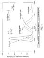
- Ambient PM is divided by most authors into the following categories based on their aerodynamic diameter (the aerodynamic diameter is defined as the diameter of a 1 g/cm 3 density sphere of the same settling velocity in air as the measured particle):
- Diesel filters can be defined as deep-bed filters and/or surface-type filters. In deep-bed filters, the mean pore size of filter media is bigger than the mean diameter of collected particles. The particles are deposited on the media through a combination of depth filtration mechanisms, including diffusional deposition (Brownian motion), inertial deposition (impaction) and flow-line interception (Brownian motion or inertia).
- depth filtration mechanisms including diffusional deposition (Brownian motion), inertial deposition (impaction) and flow-line interception (Brownian motion or inertia).
- the pore diameter of the filter media is less than the diameter of the PM, so PM is separated by sieving. Separation is done by a build-up of collected diesel PM itself, which build-up is commonly referred to as “filtration cake” and the process as “cake filtration”.
- diesel particulate filters such as ceramic wallflow monoliths
- Depth filtration is characterized by somewhat lower filtration efficiency and lower pressure drop than the cake filtration.
- WO 2008/136232 A1 discloses a honeycomb filter having a cell wall composed of a porous cell wall base material and, provided on its inflow side only or on its inflow and outflow sides, a surface layer and satisfying the following requirements (1) to (5) is used as a diesel particulate filter: (1) the peak pore diameter of the surface layer is identical with or smaller than the average pore diameter of the cell wall base material, and the porosity of the surface layer is larger than that of the cell wall base material; (2) with respect to the surface layer, the peak pore diameter is from 0.3 to less than 20 ⁇ m, and the porosity is from 60 to less than 95% (measured by mercury penetration method); (3) the thickness (L1) of the surface layer is from 0.5 to less than 30% of the thickness (L2) of the cell wall; (4) the mass of the surface layer per filtration area is from 0.01 to less than 6 mg/cm 2 ; and (5) with respect to the cell wall base material, the average pore diameter is from 10 to less than 60 ⁇ m, and the po
- PM generated by positive ignition engines has a significantly higher proportion of ultrafine, with negligible accumulation and coarse mode compared with that produced by diesel (compression ignition) engines, and this presents challenges to removing it from positive ignition engine exhaust gas in order to prevent its emission to atmosphere.
- a majority of PM derived from a positive ignition engine is relatively small compared with the size distribution for diesel PM, it is not practically possible to use a filter substrate that promotes positive ignition PM surface-type cake filtration because the relatively low mean pore size of the filter substrate that would be required would produce impractically high backpressure in the system.
- Another difficulty is combining filtration efficiency with a washcoat loading, e.g. of catalyst for meeting emission standards for non-PM pollutants, at acceptable backpressures.
- Diesel wallflow particulate filters in commercially available vehicles today have a mean pore size of about 13 ⁇ m
- washcoating a filter of this type at a sufficient catalyst loading such as is described in US 2006/0133969 to achieve required gasoline (positive ignition) emission standards can cause unacceptable backpressure.
- the claimed filter appears to be designed for inclusion in a system for location downstream of a three-way catalyst comprising a flowthrough substrate monolith.
- WO 2009/043390 discloses a catalytically active particulate filter comprising a filter element and a catalytically active coating composed of two layers.
- the first layer is in contact with the in-flowing exhaust gas while the second layer is in contact with the out-flowing exhaust gas. Both layers contain aluminium oxide.
- the first layer contains palladium, the second layer contains an oxygen-storing mixed cerium/zirconium oxide in addition to rhodium.
- a wallflow filter substrate of unspecified mean pore size is coated with a first layer at a loading of approximately 31 g/l and a second layer at a loading of approximately 30 g/l. That is, the washcoat loading is less than 1.00 g in -3 (61.02g/l). For a majority of vehicle applications, this coated filter is unlikely to be able to meet the required emission standards alone.
- a relatively porous particulate filter - such as a particulate filter adapted for a diesel application - so that it can be used to trap e.g. ultrafine positive ignition PM at an acceptable pressure drop and backpressure.
- our inventors have determined that a washcoat that hinders access of the PM to a porous structure of a filter substrate can beneficially promote surface filtration substantially at the expense of depth filtration to the extent that cake filtration of PM derived from a positive ignition engine is promoted or enhanced.
- the invention provides a positive ignition engine comprising an exhaust system comprising a filter for filtering particulate matter (PM) from exhaust gas emitted from the positive ignition engine, which filter comprising a porous substrate having inlet surfaces and outlet surfaces, wherein the inlet surfaces are separated from the outlet surfaces by a porous structure containing pores of a first mean pore size, wherein at least the inlet surfaces of the porous substrate are coated with a porous catalytic surface washcoat layer comprising a plurality of solid particles having a D90 in the range 12 to 25 ⁇ m, wherein the porous catalytic surface washcoat layer substantially covers surface pores of the porous structure and the pores of the washcoated porous substrate are defined in part by spaces between the particles (interparticle pores) in the washcoat, wherein the mean interparticle pore size is 5.0nm to 5.0 ⁇ m, wherein the porous structure of the washcoated porous substrate contains pores of a second mean pore size, wherein the second mean pore size is less than the first mean pore size
- Positive ignition engines for use in this aspect of the invention can be fuelled by gasoline fuel, gasoline fuel blended with oxygenates including methanol and/or ethanol, liquid petroleum gas or compressed natural gas.
- the positive ignition engine is a direct injection positive ignition engine.
- US patent no. 7062904 discloses a particulate filter useful in treating exhaust from a diesel-powered vehicle.
- the particulate filter comprises filter elements for removing particulate matter and an ammonia SCR catalyst.
- Ammonia can be produced during regeneration of a NOx adsorbant.
- the adsorbant can be contained in a separate device upstream of the particulate filter or be incorporated within the particulate filter.
- 7062904 relates to a method of cleaning exhaust comprising passing the exhaust over an NOx adsorber to adsorb a portion of NOx from the exhaust; passing the exhaust through a particulate filter to remove particulate matter from the exhaust; and removing a further portion of NOx from the exhaust by reducing it with ammonia over an ammonia SCR catalyst.
- a catalyst contained within the adsorbant provides NO 2 for continuously regenerating the particulate filter.
- the invention relates to the field of pollution control devices for internal combustion engines, especially diesel engines and lean burn gasoline engines, but the Detailed Description of the Invention discloses filters and exhaust systems for diesel engines; there is no specific disclosure of a filter or exhaust system for a leanbum gasoline engine.
- the present invention is capable of reducing positive ignition engine particle number emissions by >30% such as >50% e.g. >80% or even >90% at acceptable backpressure.
- Mean pore size can be determined by mercury porosimetry.
- Porosity is a measure of the percentage of void space in a porous substrate and is related to backpressure in an exhaust system: generally, the lower the porosity, the higher the backpressure.
- porosity of filters for use in the present invention are typically >40% or >50% and porosities of 45-75% such as 50-65% or 55-60% can be used with advantage.
- the mean pore size of the washcoated porous substrate is important for filtration. So, it is possible to have a porous substrate of relatively high porosity that is a poor filter because the mean pore size is also relatively high.
- the porous substrate is a ceramic wallflow filter comprising a ceramic porous filter substrate having a plurality of inlet channels and a plurality of outlet channels, wherein each inlet channel and each outlet channel is defined in part by a ceramic wall of porous structure, wherein each inlet channel is separated from an outlet channel by a ceramic wall of porous structure.
- This filter arrangement is also disclosed in SAE 810114, and reference can be made to this document for further details.
- the filter can be a ceramic foam.
- a washcoat is employed to introduce catalytic components to the filter substrate, e.g. catalysts for oxidising NO to NO 2 , yet a significant problem is to avoid backpressure issues as soot is accumulated. Accordingly, a balance is struck between the desired catalytic activity and acceptable backpressure. Contrastingly, a primary motivating factor for washcoating a porous substrate for use in the present invention is to achieve both a desired filtration efficiency and catalytic activity.
- the first mean pore size e.g. of surface pores of the porous structure of the porous filter substrate is from 8 to 45 ⁇ m, for example 8 to 25 ⁇ m, 10 to 20 ⁇ m or 10 to 15 ⁇ m.
- the first mean pore size is >18 ⁇ m such as from 15 to 45 ⁇ m, 20 to 45 ⁇ m e.g. 20 to 30 ⁇ m, or 25 to 45 ⁇ m.
- the filter has a washcoat loading of>0.25 g in -3 (>4.10gcm -3 ), such as >0.5g in -3 (>8.19gcm -3 ) or ⁇ 0.80 g in -3 (>13.11gcm -3 ), e.g. 0.80 to 3.00 g in -3 (13.11-49.16gcm -3 ).
- the washcoat loading is >1.00 g in -3 (>16.39gcm -3 ) such as >1.2 g in -3 (19.66gcm -3 ), >1.5 g in -3 (>24.58gcm -3 ), >1.6 g in -3 (>26.22gcm -3 ) or >2.00 g in -3 (32.77gcm -3 ) or for example 1.6 to 2.4 g in -3 (26.22-39.33 gcm -3 ).
- filter mean pore size and washcoat loading the filter combines a desirable level of particulate filtration and catalytic activity at acceptable backpressure.
- the filter for use in the present invention comprises a surface washcoat, wherein a washcoat layer substantially covers surface pores of the porous structure and the pores of the washcoated porous substrate are defined in part by spaces between the particles (interparticle pores) in the washcoat. That is, substantially no washcoat enters the porous structure of the porous substrate.
- Methods of making surface coated porous filter substrates include introducing a polymer, e.g. poly vinyl alcohol (PVA), into the porous structure, applying a washcoat to the porous filter substrate including the polymer and drying, then calcining the coated substrate to burn out the polymer.
- PVA poly vinyl alcohol
- an average interparticle pore size of the porous washcoat is 5.0nm to 5.0 ⁇ m, such as 0.1-1.0 ⁇ m.
- the D90 of the solid washcoat particles in a filter for use in an exhaust system for a positive ignition engine according to the invention is 12 to 25 ⁇ m.
- "D90" as used herein defines the particle size distribution in a washcoat wherein 90% of the particles present have a diameter within the range specified.
- the washcoat formulations can be the same or different.
- the mean pore size of washcoat on the inlet surfaces can be different from the mean pore size of washcoat on the outlet surfaces.
- the mean pore size of washcoat on the inlet surfaces can be less than the mean pore size of washcoat on the outlet surfaces.
- a mean pore size of washcoat on the outlet surfaces can be greater than a mean pore size of the porous substrate.
- the mean pore size of a washcoat applied to inlet surfaces Whilst it is possible for the mean pore size of a washcoat applied to inlet surfaces to be greater than the mean pore size of the porous substrate, it is advantageous to have washcoat having smaller pores than the porous substrate in washcoat on inlet surfaces to prevent or reduce any combustion ash or debris entering the porous structure.
- a TWC or NO x absorber for use in the present invention can contain one or more platinum group metals, particularly those selected from the group consisting of platinum, palladium and rhodium.
- the engine should be operated in such a way that the air-to-fuel ratio of the combustion mixture produces the stoichiometrically balanced exhaust gas composition.
- the reduction of NO x to N 2 using a TWC is less efficient when the exhaust gas composition is lean of stoichiometric. Equally, the TWC is less able to oxidise CO and HC when the exhaust gas composition is rich. The challenge, therefore, is to maintain the composition of the exhaust gas flowing into the TWC at as close to the stoichiometric composition as possible.
- the air-to-fuel ratio is controlled by an engine control unit, which receives information about the exhaust gas composition from an exhaust gas oxygen (EGO) (or lambda) sensor: a so-called closed loop feedback system.
- EGO exhaust gas oxygen
- lambda lambda
- the oxygen concentration can be adjusted by a number of means, e.g. throttling, injection of additional hydrocarbon fuel into an engine cylinder such as during the exhaust stroke or injecting hydrocarbon fuel directly into exhaust gas downstream of an engine manifold.
- the reactive barium species is given as the oxide. However, it is understood that in the presence of air most of the barium is in the form of the carbonate or possibly the hydroxide. The skilled person can adapt the above reaction schemes accordingly for species of barium other than the oxide and sequence of catalytic coatings in the exhaust stream.
- the washcoat comprises at least one molecular sieve, such as an aluminosilicate zeolite or a SAPO, for trapping positive ignition PM.
- the at least one molecular sieve can be a small, a medium or a large pore molecular sieve, for example.
- small pore molecular sieve herein we mean molecular sieves containing a maximum ring size of 8, such as CHA; by “medium pore molecular sieve” herein we mean a molecular sieve containing a maximum ring size of 10, such as ZSM-5; and by "large pore molecular sieve” herein we mean a molecular sieve having a maximum ring size of 12, such as beta.
- Small pore molecular sieves are potentially advantageous for use in SCR catalysts - see for example WO 2008/132452 .
- Particular molecular sieves with application in the present invention are selected from the group consisting of AEI, ZSM-5, ZSM-20, ERI including ZSM-34, mordenite, ferrierite, BEA including Beta, Y, CHA, LEV including Nu-3, MCM-22 and EU-1.
- the molecular sieves for use in the present invention i.e. a process for selectively catalysing the reduction of nitrogen oxides in positive ignition exhaust gas using a nitrogenous reductant (so-called "NH 3 -SCR") are metallised with at least one metal selected from the group consisting of Ce, Fe and Cu.
- a nitrogenous reductant so-called "NH 3 -SCR”
- metals selected from the group consisting of Ce, Fe and Cu.
- the cell density of diesel wallflow filters in practical use can be different from wallflow filters for use in the present invention in that the cell density of diesel wallflow filters is generally 300 cells per square inch (cpsi) (46.5 cells cm -2 ) or less, e.g. 100 cpsi (15.5 cells cm -2 ) or 200 cpsi (31.00 cells cm -2 ), so that the relatively larger diesel PM components can enter inlet channels of the filter without becoming impacted on the solid frontal area of the diesel particulate filter, thereby caking and fouling access to the open channels, whereas wallflow filters for use in the present invention can be up to 300 cpsi (46.5 cells cm -2 ) or greater, such as 350 cpsi (54.25 cells cm -2 ), 400 cpsi (62.00 cells cm -2 ), 600 cpsi (93.00 cells cm -2 ), 900 cpsi (139.50 cells cm -2 ) or even 1200 cpsi (186.00 cells cm -2
- An advantage of using higher cell densities is that the filter can have a reduced cross-section, e.g. diameter, than diesel particulate filters, which is a useful practical advantage that increases design options for locating exhaust systems on a vehicle.
- Figures 2A-C show a cross-section through a porous filter substrate 10 comprising a surface pore 12.
- Figure 2A shows an embodiment according to the present invention, featuring a porous surface washcoat layer 14 comprised of solid washcoat particles, the spaces between which particles define pores (interparticle pores). It can be seen that the washcoat layer 14 substantially covers the pore 12 of the porous structure and that a mean pore size of the interparticle pores 16 is less than the mean pore size 12 of the porous filter substrate 10.
- Figure 2C shows a further arrangement not according to the invention for the purposes of comparison only wherein the washcoat 14 sits substantially within, i.e. permeates, the porous 12 structure of the porous substrate 10.
- Figure 4 sets out a matrix showing preliminary results for a washcoat loading study for a three-way catalyst washcoat (not according to the invention) on three wallflow filters having different mean pore sizes.
- there is a band of acceptable backpressure and filtration starting with a combination of 13 ⁇ m mean pore size wallflow filter and relatively low washcoat loading (0.4 g in -3 (6.55gcm -3 )) through the 20 ⁇ m and 13 ⁇ m pore size substrates having 0.8 g in -3 (13.11gcm -3 ) to the 1.6 and 2.4 g in -3 (26.22 and 39.33 gcm -3 ) loadings on the 38 ⁇ m and 20 ⁇ m mean pore size substrates.
- washcoat loadings of ⁇ 1.6 g in -3 (26.22 gem -3 ) are preferred for acceptable three-way catalyst activity in a stand-alone product.
- the invention allows a combination of sufficient three-way catalyst activity and PM filtration to be achieved without a significant increase in backpressure. Increased washcoat loadings on lower mean pore size wallflow filter substrates can only be used in applications that can tolerate increased backpressure.
- a benefit of the invention is that a state-of-the-art three-way catalyst comprising a flow-through monolith substrate that is typically located on a vehicle in either an underfloor or close-coupled location can be replaced with a filter according to the invention to provide sufficient three-way activity to meet legislative requirements for gaseous HC, CO and NO x emissions, while also meeting particle number standards as required by e.g. Euro 6 standards.
- the filter according to the present invention can be used as a standalone catalytic exhaust system aftertreatment component. That is, in certain applications the filter according to the present invention is adjacent and in direct fluid communication with the engine without intervening catalysts therebetween; and/or an exit to atmosphere from an exhaust gas aftertreatment system is adjacent to and in direct fluid communication with the filter according to the present invention without intervening catalysts therebetween.
- An additional requirement of a TWC is a need to provide a diagnosis function for its useful life, so called "on-board diagnostics" or OBD.
- OBD on-board diagnostics
- a problem in OBD arises where there is insufficient oxygen storage capacity in the TWC, because OBD processes for TWCs use remaining oxygen storage capacity to diagnose remaining catalyst function.
- insufficient washcoat is loaded on the filter such as in the specific Examples disclosed in US 2009/0193796 and WO 2009/043390 , there may not be enough OSC present to provide an accurate OSC "delta" for OBD purposes. Since the present invention enables washcoat loadings approaching current state-of-the-art TWCs, the filters for use in the present invention can be used with advantage in current OBD processes.
- TWC three-way catalyst
- the coatings were applied to 4.66 x 4.5 inch (11.84 x 11.43 cm) 300 cells per square inch (46.5 cells cm -2 ) cordierite wallflow filter substrates having 12 thousandths of an inch (30.48x10 -3 cm) wall thickness ("300/12") with a nominal average pore size of 20 micrometres (hereinafter "microns") (62% porosity).
- Each filter was hydrothermally oven-aged at 980°C for 4 hours and installed in a close-coupled position on a Euro 5 passenger car with a 1.4L direct injection gasoline engine.
- Each filter was evaluated over a minimum of three MVEG-B drive cycles, measuring the reduction in particle number emissions relative to a reference catalyst, wherein the filter was exchanged for a TWC coated onto a flowthrough substrate monolith at the same washcoat and precious metal loadings - and the backpressure differential was determined between sensors mounted upstream and downstream of the filter (or reference catalyst).
- the Euro 5/6 implementing legislation introduces a new PM mass emission measurement method developed by the UN/ECE Particulate Measurement Programme (PMP) which adjusts the PM mass emission limits to account for differences in results using old and the new methods.
- PMP Particulate Measurement Programme
- the Euro 5/6 legislation also introduces a particle number emission limit (PMP method), in addition to the mass-based limits.
- Table 1 demonstrate that the filters prepared with the larger particle size "on-wall” washcoat have significantly improved particle number reduction than the filters prepared with the smaller particle size "in-wall” washcoat, with a small, but acceptable, increase in peak backpressure.
- Table 1 Effect of washcoat location within filter on particle number reduction and backpressure (BP) Sample filter properties Washcoat type % PN reduction vs. flow through reference Average BP (mbar(Pa)) on 70 kph cruise of MVEG-B drive cycle Peak BP (mbar(Pa)) during any one MVEG-B drive cycle 20 ⁇ m, 62% "In-wall” 75 14.3 (1430) 73.5 (7350) 20 ⁇ m, 62% "On-wall” 83 16.2 (1620) 104.2 (10420)
- Each filter was hydrothermally oven-aged at 980°C for 4 hours and installed in the underfloor position on a Euro 4 passenger car with a 1.4L direct injection gasoline engine, with a fully formulated three-way catalyst coated on a flowthrough substrate monolith located in the close-coupled position, i.e. upstream of the filter.
- Each filter was evaluated over a minimum of three MVEG-B drive cycles, measuring the reduction in particle number emissions relative to a reference system, wherein the underfloor filter was exchanged for a TWC coated on a flowthrough substrate monolith at identical washcoat and palladium loadings and the backpressure differential was determined between sensors mounted upstream of the close-coupled TWC and downstream of the filter (or reference catalyst).
- the peak backpressure results given in Table 2 are the backpressure reading on the third repeat of the MVEG-B cycle.
- Each filter was evaluated over a minimum of three MVEG-B drive cycles, measuring the reduction in particle number emissions relative to a reference catalyst, wherein the close-coupled filter was exchanged for a TWC coated on a flowthrough substrate monolith at an identical washcoat and precious metal loading, the backpressure differential and the conversion efficiency for gaseous HC, CO and NO x emissions were determined between sensors mounted upstream and downstream of the filter (or reference catalyst).
- NMHC non-methane hydrocarbons
- the "engineering target” is often used by the vehicle manufacturers and represents a percentage of the legislated emissions. For the purposes of these Examples, we have used an engineering target of 80%. Since the Euro 6 NMHC standard is 68mg/km, the engineering target is 54mg/km. The calculated percentage of this number is used to assess the reduction in NMHC results achieved over the MVEG-B drive cycle. This gives values above and below 100% that relate well to the acceptable three-way catalyst activity.
- Each filter was hydrothermally oven aged at 980°C for 4 hours and installed in a close-coupled position on a Euro 4 passenger car with a 1.4L direct injection gasoline engine.
- Each filter was evaluated over a minimum of three MVEG-B drive cycles, measuring the reduction in particle number emissions relative to a reference catalyst, wherein the close-coupled filter was exchanged for a TWC coated on a flowthrough substrate monolith at an identical washcoat and precious metal loading, the backpressure differential and the conversion efficiency for gaseous HC, CO and NO x emissions were determined between sensors mounted upstream and downstream of the filter (or reference catalyst). Only non-methane hydrocarbons (NMHC) conversion is reported in Table 4.
- NMHC non-methane hydrocarbons
- a smaller pore sample was not evaluated because, from the results obtained from the Example 2, the backpressure was expected to be too great for the Euro 5 passenger car in this test.
- Each filter was hydrothermally oven-aged at 980°C for 4 hours and installed in a close-coupled position on a Euro 5 passenger car with a 1.4L direct injection gasoline engine.
- the filters were evaluated over a minimum of three MVEG-B drive cycles, measuring the reduction in particle number emissions relative to a reference catalyst, wherein the close-coupled filter was exchanged for a TWC coated on a flowthrough substrate monolith at an identical washcoat and precious metal loading, the backpressure differential and the conversion efficiency for gaseous HC, CO and NO x emissions were determined between sensors mounted upstream and downstream of the filter (or reference catalyst). Only non-methane hydrocarbons (NMHC) conversion is reported in Table 5.
- NMHC non-methane hydrocarbons
- a Euro 5 passenger car with a 2.0L direct injection gasoline engine equipped with a fully formulated three-way catalyst coated on a flowthrough substrate monolith in the close-coupled position was tested over the MVEG-B and FTP (Federal Test Procedure) 75 drive cycles.
- the number of particles emitted over the MVEG-B drive cycle was measured according to the PMP methodology.
- the mass of particulate matter emitted over the FTP 75 drive cycle was measured following standard protocols.
- Table 7 demonstrate that fitment of the additional coated filter reduced particle number emissions over the MVEG-B cycle by ⁇ 99% and reduced the particulate mass emitted over the FTP 75 cycle by ⁇ 75% relative to the flowthrough TWC-only system. Depending what CARB PM emission standard is adopted, the 2.7 mg PM/mile (1.68mg/km) figure could fail that standard. Table 7. Effect of filter fitment on particulate number and mass emissions Catalyst system PN emissions over MVEG-B drive cycle (#/km) PM emissions over FTP 75 drive cycle (mg/mi) (mg/km) Flowthrough TWC only 4.42 x 10 12 2.7 (1.6 8) Flowthrough TWC + Coated filter 4.69 x 10 10 0.6 (0.3 7)
Description
- The present invention relates to a filter for use in treating particulate matter (PM) in exhaust gas derived from any combustion process where it is not possible to remove PM from the exhaust gas by build-up of PM (so-called "cake filtration") or by a combination of depth filtration and cake filtration. The combustion process is typically that of a vehicular engine. In particular, the invention relates to a filter for use in treating PM derived from a vehicular positive ignition engine, particularly stoichiometrically operated positive ignition engines but also lean-bum positive ignition engines.
- Positive ignition engines cause combustion of a hydrocarbon and air mixture using spark ignition. Contrastingly, compression ignition engines cause combustion of a hydrocarbon by injecting the hydrocarbon into compressed air. Positive ignition engines can be fuelled by gasoline fuel, gasoline fuel blended with oxygenates including methanol and/or ethanol, liquid petroleum gas or compressed natural gas.
- Ambient PM is divided by most authors into the following categories based on their aerodynamic diameter (the aerodynamic diameter is defined as the diameter of a 1 g/cm3 density sphere of the same settling velocity in air as the measured particle):
- (i) PM-10 - particles of an aerodynamic diameter of less than 10 µm;
- (ii) Fine particles of diameters below 2.5 µm (PM-2.5);
- (iii) Ultrafine particles of diameters below 0.1 µm (or 100 nm); and
- (iv) Nanoparticles, characterised by diameters of less than 50 nm.
- Since the mid-1990's, particle size distributions of particulates exhausted from internal combustion engines have received increasing attention due to possible adverse health effects of fine and ultrafine particles. Concentrations of PM-10 particulates in ambient air are regulated by law in the USA. A new, additional ambient air quality standard for PM-2.5 was introduced in the USA in 1997 as a result of health studies that indicated a strong correlation between human mortality and the concentration of fine particles below 2.5 µm
- Interest has now shifted towards nanoparticles generated by diesel and gasoline engines because they are understood to penetrate more deeply into human lungs than particulates of greater size and consequently they are believed to be more harmful than larger particles, extrapolated from the findings of studies into particulates in the 2.5-10.0 µm range.
- Size distributions of diesel particulates have a well-established bimodal character that correspond to the particle nucleation and agglomeration mechanisms, with the corresponding particle types referred to as the nuclei mode and the accumulation mode respectively (see
Figure 1 ). As can be seen fromFigure 1 , in the nuclei mode, diesel PM is composed of numerous small particles holding very little mass. Nearly all diesel particulates have sizes of significantly less than 1 µm, i.e. they comprise a mixture of fine, i.e. falling under the 1997 US law, ultrafine and nanoparticles. - Nuclei mode particles are believed to be composed mostly of volatile condensates (hydrocarbons, sulfuric acid, nitric acid etc.) and contain little solid material, such as ash and carbon. Accumulation mode particles are understood to comprise solids (carbon, metallic ash etc.) intermixed with condensates and adsorbed material (heavy hydrocarbons, sulfur species, nitrogen oxide derivatives etc.) Coarse mode particles are not believed to be generated in the diesel combustion process and may be formed through mechanisms such as deposition and subsequent re-entrainment of particulate material from the walls of an engine cylinder, exhaust system, or the particulate sampling system. The relationship between these modes is shown in
Figure 1 . - The composition of nucleating particles may change with engine operating conditions, environmental condition (particularly temperature and humidity), dilution and sampling system conditions. Laboratory work and theory have shown that most of the nuclei mode formation and growth occur in the low dilution ratio range. In this range, gas to particle conversion of volatile particle precursors, like heavy hydrocarbons and sulfuric acid, leads to simultaneous nucleation and growth of the nuclei mode and adsorption onto existing particles in the accumulation mode. Laboratory tests (see e.g. SAE 980525 and SAE 2001-01-0201) have shown that nuclei mode formation increases strongly with decreasing air dilution temperature but there is conflicting evidence on whether humidity has an influence.
- Generally, low temperature, low dilution ratios, high humidity and long residence times favour nanoparticles formation and growth. Studies have shown that nanoparticles consist mainly of volatile material like heavy hydrocarbons and sulfuric acid with evidence of solid fraction only at very high loads.
- Contrastingly, engine-out size distributions of gasoline particulates in steady state operation show a unimodal distribution with a peak of about 60-80nm (see e.g.
Figure 4 in SAE 1999-01-3530). By comparison with diesel size distribution, gasoline PM is predominantly ultrafine with negligible accumulation and coarse mode. - Particulate collection of diesel particulates in a diesel particulate filter is based on the principle of separating gas-borne particulates from the gas phase using a porous barrier. Diesel filters can be defined as deep-bed filters and/or surface-type filters. In deep-bed filters, the mean pore size of filter media is bigger than the mean diameter of collected particles. The particles are deposited on the media through a combination of depth filtration mechanisms, including diffusional deposition (Brownian motion), inertial deposition (impaction) and flow-line interception (Brownian motion or inertia).
- In surface-type filters, the pore diameter of the filter media is less than the diameter of the PM, so PM is separated by sieving. Separation is done by a build-up of collected diesel PM itself, which build-up is commonly referred to as "filtration cake" and the process as "cake filtration".
- It is understood that diesel particulate filters, such as ceramic wallflow monoliths, may work through a combination of depth and surface filtration: a filtration cake develops at higher soot loads when the depth filtration capacity is saturated and a particulate layer starts covering the filtration surface. Depth filtration is characterized by somewhat lower filtration efficiency and lower pressure drop than the cake filtration.
-
WO 03/011437 GB-A-2350804 -
WO 2008/136232 A1 discloses a honeycomb filter having a cell wall composed of a porous cell wall base material and, provided on its inflow side only or on its inflow and outflow sides, a surface layer and satisfying the following requirements (1) to (5) is used as a diesel particulate filter: (1) the peak pore diameter of the surface layer is identical with or smaller than the average pore diameter of the cell wall base material, and the porosity of the surface layer is larger than that of the cell wall base material; (2) with respect to the surface layer, the peak pore diameter is from 0.3 to less than 20 µm, and the porosity is from 60 to less than 95% (measured by mercury penetration method); (3) the thickness (L1) of the surface layer is from 0.5 to less than 30% of the thickness (L2) of the cell wall; (4) the mass of the surface layer per filtration area is from 0.01 to less than 6 mg/cm2; and (5) with respect to the cell wall base material, the average pore diameter is from 10 to less than 60 µm, and the porosity is from 40 to less than 65%. See also SAE paper no. 2009-01-0292. - Other techniques suggested in the art for separating gasoline PM from the gas phase include vortex recovery.
- Emission legislation in Europe from 1st September 2014 (Euro 6) requires control of the number of particles emitted from both diesel and gasoline (positive ignition) passenger cars. For gasoline EU light duty vehicles the allowable limits are: 1000mg/km carbon monoxide; 60mg/km nitrogen oxides (NOx); 100mg/km total hydrocarbons (of which ≤ 68mg/km are non-methane hydrocarbons); and 4.5mg/km particulate matter ((PM) for direct injection engines only). Although the authorities have not set the PM number standard for Euro 6 yet, it is widely understood that it will be set at 6.0 x 10¹¹ per km. The present specification is based on the assumption that this number will be adopted in due course.
- In the United States, no similar emission standards have been set. However, the State of California Air Resources Board (CARB) recently published a paper entitled "Preliminary Discussion Paper - Amendments to California's Low-Emission Vehicle [LEV] Regulations for Criteria Pollutants - LEV III" (release date 8th February 2010) in which a new PM standard of between 2 and 4 mg PM/mile (1.25-2.50 mg PM/km (currently 10mg PM/mile (6.25 mg PM/km))) is proposed, the paper commenting that: "Staff has received input from a number of manufacturers suggesting that a standard of 3 mg PM/mile (1.88 mg PM/km) can be met for gasoline direct injection engines without requiring the use of particulate filters." Additionally, the paper states that since the PM mass and count emissions appear to be correlated: "Although a mandatory number standard is not being considered at this time, an optional PM number standard of about 1012 particles/mile [6.2511 particles/km] is being considered (which could be chosen by manufacturers instead of the PM mass standard)". However, since neither the PM standard nor the PM number standard has been set by CARB yet, it is too soon to know whether particulate filtration will be necessary for the Californian or US vehicle market generally. It is nevertheless possible that certain vehicle manufacturers will choose filters in order to provide a margin of safety on any positive ignition engine design options selected to meet whatever standards are eventually set.
- The new Euro 6 emission standard presents a number of challenging design problems for meeting gasoline emission standards. In particular, how to design a filter, or an exhaust system including a filter, for reducing the number of PM gasoline (positive ignition) emissions, yet at the same time meeting the emission standards for non-PM pollutants such as one or more of oxides of nitrogen (NOx), carbon monoxide (CO) and unburned hydrocarbons (HC), all at an acceptable back pressure, e.g. as measured by maximum on-cycle backpressure on the EU drive cycle.
- It is envisaged that a minimum of particle reduction for a three-way catalysed particulate filter to meet the Euro 6 PM number standard relative to an equivalent flowthrough catalyst is ≥50%. Additionally, while some backpressure increase for a three-way catalysed wallflow filter relative to an equivalent flowthrough catalyst is inevitable, in our experience peak backpressure over the MVEG-B drive cycle (average over three tests from "fresh") for a majority of passenger vehicles should be limited to <200 mbar (<20000 Pa), such as <180 mbar (<18000 Pa), <150 mbar (<15000 Pa) and preferably <120 mbar (<12000 Pa) e.g. <100 mbar (<10000 Pa).
- PM generated by positive ignition engines has a significantly higher proportion of ultrafine, with negligible accumulation and coarse mode compared with that produced by diesel (compression ignition) engines, and this presents challenges to removing it from positive ignition engine exhaust gas in order to prevent its emission to atmosphere. In particular, since a majority of PM derived from a positive ignition engine is relatively small compared with the size distribution for diesel PM, it is not practically possible to use a filter substrate that promotes positive ignition PM surface-type cake filtration because the relatively low mean pore size of the filter substrate that would be required would produce impractically high backpressure in the system.
- Furthermore, generally it is not possible to use a conventional wallflow filter, designed for trapping diesel PM, for promoting surface-type filtration of PM from a positive ignition engine in order to meet relevant emission standards because there is generally less PM in positive ignition exhaust gas, so formation of a soot cake is less likely; and positive ignition exhaust gas temperatures are generally higher, which can lead to faster removal of PM by oxidation, thus preventing increased PM removal by cake filtration. Depth filtration of positive ignition PM in a conventional diesel wallflow filter is also difficult because the PM is significantly smaller than the pore size of the filter medium. Hence, in normal operation, an uncoated conventional diesel wallflow filter will have a lower filtration efficiency when used with a positive ignition engine than a compression ignition engine.
- Another difficulty is combining filtration efficiency with a washcoat loading, e.g. of catalyst for meeting emission standards for non-PM pollutants, at acceptable backpressures. Diesel wallflow particulate filters in commercially available vehicles today have a mean pore size of about 13µm However, we have found that washcoating a filter of this type at a sufficient catalyst loading such as is described in
US 2006/0133969 to achieve required gasoline (positive ignition) emission standards can cause unacceptable backpressure. - In order to reduce filter backpressure it is possible to reduce the length of the substrate. However, there is a finite level below which the backpressure increases as the filter length is reduced. Suitable filter lengths for filters according to the present invention are from 2-12 inches (5.08-30.48cm) long, preferably 3-6 inches (7.62-15.24cm) long. Cross sections can be circular and in our development work we have used 4.66 and 5.66 inch (11.84 and 14.38 cm) diameter filters. However, cross-section can also be dictated by space on a vehicle into which the filter is required to fit. So for filters located in the so-called close coupled position, e.g. within 50 cm of the engine exhaust manifold where space is at a premium, elliptical or oval filter cross sections can be contemplated. As would be expected, backpressure also increases with washcoat loading and soot loading.
- There have been a number of recent efforts to combine three-way catalysts with filters for meeting the Euro 6 emission standards.
-
US 2009/0193796 discloses a three-way conversion catalyst coated onto a particulate trap. The Examples disclose e.g. a soot filter having a catalytic material prepared using two coats: an inlet coat and an outlet coat. The mean pore size of the soot filter substrate used is not mentioned. The inlet coat contains alumina, an oxygen storage component (OSC) and rhodium all at a total loading of 0.17 g in-3 (2.79gcm-3); the outlet coat includes alumina, an OSC and palladium, all at a total loading of 0.42 g in-3 (6.88gcm-3). However, we believe that the three-way catalyst washcoat loading of <0.5 g in-3 (<8.19gcm-3) provides insufficient three-way activity to meet the required emission standards alone, i.e. the claimed filter appears to be designed for inclusion in a system for location downstream of a three-way catalyst comprising a flowthrough substrate monolith. -
WO 2009/043390 discloses a catalytically active particulate filter comprising a filter element and a catalytically active coating composed of two layers. The first layer is in contact with the in-flowing exhaust gas while the second layer is in contact with the out-flowing exhaust gas. Both layers contain aluminium oxide. The first layer contains palladium, the second layer contains an oxygen-storing mixed cerium/zirconium oxide in addition to rhodium. In Examples, a wallflow filter substrate of unspecified mean pore size is coated with a first layer at a loading of approximately 31 g/l and a second layer at a loading of approximately 30 g/l. That is, the washcoat loading is less than 1.00 g in-3 (61.02g/l). For a majority of vehicle applications, this coated filter is unlikely to be able to meet the required emission standards alone. - We have now discovered, very surprisingly, that it is possible to adapt a relatively porous particulate filter - such as a particulate filter adapted for a diesel application - so that it can be used to trap e.g. ultrafine positive ignition PM at an acceptable pressure drop and backpressure. In particular, our inventors have determined that a washcoat that hinders access of the PM to a porous structure of a filter substrate can beneficially promote surface filtration substantially at the expense of depth filtration to the extent that cake filtration of PM derived from a positive ignition engine is promoted or enhanced.
- Early indications suggest that positive ignition PM combusts in oxygen at lower temperatures than diesel PM. Investigations are continuing, but the invention makes use of this observation by providing means for trapping the positive ignition PM for combustion in oxygen.
- According to one aspect, the invention provides a positive ignition engine comprising an exhaust system comprising a filter for filtering particulate matter (PM) from exhaust gas emitted from the positive ignition engine, which filter comprising a porous substrate having inlet surfaces and outlet surfaces, wherein the inlet surfaces are separated from the outlet surfaces by a porous structure containing pores of a first mean pore size, wherein at least the inlet surfaces of the porous substrate are coated with a porous catalytic surface washcoat layer comprising a plurality of solid particles having a D90 in the range 12 to 25µm, wherein the porous catalytic surface washcoat layer substantially covers surface pores of the porous structure and the pores of the washcoated porous substrate are defined in part by spaces between the particles (interparticle pores) in the washcoat, wherein the mean interparticle pore size is 5.0nm to 5.0µm, wherein the porous structure of the washcoated porous substrate contains pores of a second mean pore size, wherein the second mean pore size is less than the first mean pore size and wherein the catalytic washcoat is a selective catalytic reduction (SCR) catalyst for catalysing the reduction of oxides of nitrogen (NOx) with a nitrogenous reductant, which SCR catalyst comprises at least one molecular sieve, which molecular sieve is metallised with at least one metal selected from the group consisting of Ce, Fe and Cu.
- Positive ignition engines for use in this aspect of the invention can be fuelled by gasoline fuel, gasoline fuel blended with oxygenates including methanol and/or ethanol, liquid petroleum gas or compressed natural gas. In a preferred embodiment, the positive ignition engine is a direct injection positive ignition engine.
-
US patent no. 7062904 discloses a particulate filter useful in treating exhaust from a diesel-powered vehicle. The particulate filter comprises filter elements for removing particulate matter and an ammonia SCR catalyst. Ammonia can be produced during regeneration of a NOx adsorbant. The adsorbant can be contained in a separate device upstream of the particulate filter or be incorporated within the particulate filter. Another aspect of the invention disclosed inUS patent no. 7062904 relates to a method of cleaning exhaust comprising passing the exhaust over an NOx adsorber to adsorb a portion of NOx from the exhaust; passing the exhaust through a particulate filter to remove particulate matter from the exhaust; and removing a further portion of NOx from the exhaust by reducing it with ammonia over an ammonia SCR catalyst. Preferably, a catalyst contained within the adsorbant provides NO2 for continuously regenerating the particulate filter. The introduction to the disclosure states that the invention relates to the field of pollution control devices for internal combustion engines, especially diesel engines and lean burn gasoline engines, but the Detailed Description of the Invention discloses filters and exhaust systems for diesel engines; there is no specific disclosure of a filter or exhaust system for a leanbum gasoline engine. - Early indications are that the present invention is capable of reducing positive ignition engine particle number emissions by >30% such as >50% e.g. >80% or even >90% at acceptable backpressure.
- Mean pore size can be determined by mercury porosimetry.
- It will be understood that the benefit of the invention is substantially independent of the porosity of the substrate. Porosity is a measure of the percentage of void space in a porous substrate and is related to backpressure in an exhaust system: generally, the lower the porosity, the higher the backpressure. However, the porosity of filters for use in the present invention are typically >40% or >50% and porosities of 45-75% such as 50-65% or 55-60% can be used with advantage. The mean pore size of the washcoated porous substrate is important for filtration. So, it is possible to have a porous substrate of relatively high porosity that is a poor filter because the mean pore size is also relatively high.
- The porous substrate can be a metal filter, such as a sintered metal filter, a so-called partial filter, such as those disclosed in
EP 1057519 orWO 01/080978 WO 01/16050 - Reasons motivating the coating of a wallflow filter for a diesel application are typically different from that of the present invention. In diesel applications, a washcoat is employed to introduce catalytic components to the filter substrate, e.g. catalysts for oxidising NO to NO2, yet a significant problem is to avoid backpressure issues as soot is accumulated. Accordingly, a balance is struck between the desired catalytic activity and acceptable backpressure. Contrastingly, a primary motivating factor for washcoating a porous substrate for use in the present invention is to achieve both a desired filtration efficiency and catalytic activity.
- In one embodiment, the first mean pore size e.g. of surface pores of the porous structure of the porous filter substrate is from 8 to 45µm, for example 8 to 25µm, 10 to 20µm or 10 to 15µm. In particular embodiments, the first mean pore size is >18µm such as from 15 to 45µm, 20 to 45µm e.g. 20 to 30µm, or 25 to 45µm.
- In embodiments, the filter has a washcoat loading of>0.25 g in-3 (>4.10gcm-3), such as >0.5g in-3 (>8.19gcm-3) or ≥0.80 g in-3 (>13.11gcm-3), e.g. 0.80 to 3.00 g in-3 (13.11-49.16gcm-3 ). In preferred embodiments, the washcoat loading is >1.00 g in-3 (>16.39gcm-3) such as >1.2 g in-3 (19.66gcm-3), >1.5 g in-3 (>24.58gcm-3), >1.6 g in-3 (>26.22gcm-3) or >2.00 g in-3 (32.77gcm-3) or for example 1.6 to 2.4 g in-3 (26.22-39.33 gcm-3). In particular combinations of filter mean pore size and washcoat loading the filter combines a desirable level of particulate filtration and catalytic activity at acceptable backpressure.
- The filter for use in the present invention comprises a surface washcoat, wherein a washcoat layer substantially covers surface pores of the porous structure and the pores of the washcoated porous substrate are defined in part by spaces between the particles (interparticle pores) in the washcoat. That is, substantially no washcoat enters the porous structure of the porous substrate. Methods of making surface coated porous filter substrates include introducing a polymer, e.g. poly vinyl alcohol (PVA), into the porous structure, applying a washcoat to the porous filter substrate including the polymer and drying, then calcining the coated substrate to burn out the polymer. A schematic representation of the first embodiment is shown in
Figure 2A . - Methods of coating porous filter substrates are known to the skilled person and include, without limitation, the method disclosed in
WO 99/47260 - In this first embodiment, which is a filter for use in an exhaust system for a positive ignition engine according to the invention, an average interparticle pore size of the porous washcoat is 5.0nm to 5.0µm, such as 0.1-1.0µm.
- The D90 of the solid washcoat particles in a filter for use in an exhaust system for a positive ignition engine according to the invention is 12 to 25µm. "D90" as used herein defines the particle size distribution in a washcoat wherein 90% of the particles present have a diameter within the range specified.
- In the first aspect of the invention, the washcoat is coated on inlet surfaces or both inlet and outlet surfaces of the porous substrate. Additionally either one or both of the inlet and outlet surfaces can include a plurality of washcoat layers, wherein each washcoat layer within the plurality of layers can be the same or different, e.g. the mean pore size in a first layer can be different from that of a second layer. In embodiments, washcoat intended for coating on outlet surfaces is not necessarily the same as for inlet surfaces.
- Where both inlet and outlet surfaces are coated, the washcoat formulations can be the same or different. Where both the inlet and the outlet surfaces are washcoated, the mean pore size of washcoat on the inlet surfaces can be different from the mean pore size of washcoat on the outlet surfaces. For example, the mean pore size of washcoat on the inlet surfaces can be less than the mean pore size of washcoat on the outlet surfaces. In the latter case, a mean pore size of washcoat on the outlet surfaces can be greater than a mean pore size of the porous substrate.
- Whilst it is possible for the mean pore size of a washcoat applied to inlet surfaces to be greater than the mean pore size of the porous substrate, it is advantageous to have washcoat having smaller pores than the porous substrate in washcoat on inlet surfaces to prevent or reduce any combustion ash or debris entering the porous structure.
-
EP 1663458 discloses a SCR filter, wherein the filter is a wallflow monolith and wherein an SCR catalyst composition permeates walls of the wallflow monolith. The specification discloses generally that the walls of the wallflow filter can contain thereon or therein (i.e. not both) one or more catalytic materials. According to the disclosure, "permeate", when used to describe the dispersion of a catalyst slurry on the wallflow monolith substrate, means the catalyst composition is dispersed throughout the wall of the substrate. - In further particular embodiments, the surface porosity of the washcoat is increased by including voids therein. Exhaust gas catalysts having such features are disclosed, e.g. in our
WO 2006/040842 andWO 2007/116881 . - By "voids" in the washcoat layer herein, we mean that a space exists in the layer defined by solid washcoat material. Voids can include any vacancy, fine pore, tunnel-state (cylinder, prismatic column), slit etc., and can be introduced by including in a washcoat composition for coating on the filter substrate a material that is combusted during calcination of a coated filter substrate, e.g. chopped cotton or materials to give rise to pores made by formation of gas on decomposition or combustion. Where voids are present, voids are different from, and therefore should not be counted towards determination of, the average interparticle pore size of the porous washcoat.
- The average void ratio of the washcoat can be from 5-80%, whereas the average diameter of the voids can be from 0.2 to 500µm, such as 10 to 250µm.
- A TWC or NOx absorber for use in the present invention can contain one or more platinum group metals, particularly those selected from the group consisting of platinum, palladium and rhodium.
- TWCs are intended to catalyse three simultaneous reactions: (i) oxidation of carbon monoxide to carbon dioxide, (ii) oxidation of unburned hydrocarbons to carbon dioxide and water; and (iii) reduction of nitrogen oxides to nitrogen and oxygen. These three reactions occur most efficiently when the TWC receives exhaust from an engine running at or about the stoichiometric point. As is well known in the art, the quantity of carbon monoxide (CO), unburned hydrocarbons (HC) and nitrogen oxides (NOx) emitted when gasoline fuel is combusted in a positive ignition (e.g. spark-ignited) internal combustion engine is influenced predominantly by the air-to-fuel ratio in the combustion cylinder. An exhaust gas having a stoichiometrically balanced composition is one in which the concentrations of oxidising gases (NOx and O2) and reducing gases (HC and CO) are substantially matched. The air-to-fuel ratio that produces the stoichiometrically balanced exhaust gas composition is typically given as 14.7:1.
- Theoretically, it should be possible to achieve complete conversion of O2, NOx, CO and HC in a stoichiometrically balanced exhaust gas composition to CO2, H2O and N2 and this is the duty of the three-way catalyst. Ideally, therefore, the engine should be operated in such a way that the air-to-fuel ratio of the combustion mixture produces the stoichiometrically balanced exhaust gas composition.
- A way of defining the compositional balance between oxidising gases and reducing gases of the exhaust gas is the lambda (λ) value of the exhaust gas, which can be defined according to equation (1) as:

- It should be appreciated that the reduction of NOx to N2 using a TWC is less efficient when the exhaust gas composition is lean of stoichiometric. Equally, the TWC is less able to oxidise CO and HC when the exhaust gas composition is rich. The challenge, therefore, is to maintain the composition of the exhaust gas flowing into the TWC at as close to the stoichiometric composition as possible.
- Of course, when the engine is in steady state it is relatively easy to ensure that the air-to-fuel ratio is stoichiometric. However, when the engine is used to propel a vehicle, the quantity of fuel required changes transiently depending upon the load demand placed on the engine by the driver. This makes controlling the air-to-fuel ratio so that a stoichiometric exhaust gas is generated for three-way conversion particularly difficult. In practice, the air-to-fuel ratio is controlled by an engine control unit, which receives information about the exhaust gas composition from an exhaust gas oxygen (EGO) (or lambda) sensor: a so-called closed loop feedback system. A feature of such a system is that the air-to-fuel ratio oscillates (or perturbates) between slightly rich of the stoichiometric (or control set) point and slightly lean, because there is a time lag associated with adjusting air-to-fuel ratio. This perturbation is characterised by the amplitude of the air-to-fuel ratio and the response frequency (Hz).
- The active components in a typical TWC comprise one or both of platinum and palladium in combination with rhodium, or even palladium only (no rhodium), supported on a high surface area oxide, and an oxygen storage component.
- When the exhaust gas composition is slightly rich of the set point, there is a need for a small amount of oxygen to consume the unreacted CO and HC, i.e. to make the reaction more stoichiometric. Conversely, when the exhaust gas goes slightly lean, the excess oxygen needs to be consumed. This was achieved by the development of the oxygen storage component that liberates or absorbs oxygen during the perturbations. The most commonly used oxygen storage component (OSC) in modem TWCs is cerium oxide (CeO2) or a mixed oxide containing cerium, e.g. a Ce/Zr mixed oxide.
- NOx absorber catalysts (NACs) are known e.g. from
US patent no. 5,473,887 and are designed to adsorb nitrogen oxides (NOx) from lean exhaust gas (lambda >1) and to desorb the NOx when the oxygen concentration in the exhaust gas is decreased. Desorbed NOx may be reduced to N2 with a suitable reductant, e.g. gasoline fuel, promoted by a catalyst component, such as rhodium, of the NAC itself or located downstream of the NAC. In practice, control of oxygen concentration can be adjusted to a desired redox composition intermittently in response to a calculated remaining NOx adsorption capacity of the NAC, e.g. richer than normal engine running operation (but still lean of stoichiometric or lambda = 1 composition), stoichiometric or rich of stoichiometric (lambda <1). The oxygen concentration can be adjusted by a number of means, e.g. throttling, injection of additional hydrocarbon fuel into an engine cylinder such as during the exhaust stroke or injecting hydrocarbon fuel directly into exhaust gas downstream of an engine manifold. - A typical NAC formulation includes a catalytic oxidation component, such as platinum, a significant quantity, i.e. substantially more than is required for use as a promoter such as a promoter in a TWC, of a NOx-storage component, such as barium, and a reduction catalyst, e.g. rhodium. One mechanism commonly given for NOx-storage from a lean exhaust gas for this formulation is:
NO + ½ O2 → NO2 (2)
; and
BaO + NO2 + ½ O2 → Ba(NO3)2 (3)
, wherein in reaction (2), the nitric oxide reacts with oxygen on active oxidation sites on the platinum to form NO2. Reaction (3) involves adsorption of the NO2 by the storage material in the form of an inorganic nitrate. - At lower oxygen concentrations and/or at elevated temperatures, the nitrate species become thermodynamically unstable and decompose, producing NO or NO2 according to reaction (4) below. In the presence of a suitable reductant, these nitrogen oxides are subsequently reduced by carbon monoxide, hydrogen and hydrocarbons to N2, which can take place over the reduction catalyst (see reaction (5)).
Ba(NO3)2 → BaO + 2NO + 3/2 O2 or Ba(NO3)2 → BaO + 2NO2 + ½ O2 (4)
; and
NO + CO →½ N2 + CO2 (5)
; (Other reactions include Ba(NO3)2 + 8H2 → BaO + 2NH3 +5H2O followed by NH3 + NOx → N2 + yH2Oor 2NH3 + 2O2 + CO →N2 + 3H2O + CO2 etc.). - In the reactions of (2)-(5) above, the reactive barium species is given as the oxide. However, it is understood that in the presence of air most of the barium is in the form of the carbonate or possibly the hydroxide. The skilled person can adapt the above reaction schemes accordingly for species of barium other than the oxide and sequence of catalytic coatings in the exhaust stream.
- The washcoat comprises at least one molecular sieve, such as an aluminosilicate zeolite or a SAPO, for trapping positive ignition PM. The at least one molecular sieve can be a small, a medium or a large pore molecular sieve, for example. By "small pore molecular sieve" herein we mean molecular sieves containing a maximum ring size of 8, such as CHA; by "medium pore molecular sieve" herein we mean a molecular sieve containing a maximum ring size of 10, such as ZSM-5; and by "large pore molecular sieve" herein we mean a molecular sieve having a maximum ring size of 12, such as beta. Small pore molecular sieves are potentially advantageous for use in SCR catalysts - see for example
WO 2008/132452 . - Particular molecular sieves with application in the present invention are selected from the group consisting of AEI, ZSM-5, ZSM-20, ERI including ZSM-34, mordenite, ferrierite, BEA including Beta, Y, CHA, LEV including Nu-3, MCM-22 and EU-1.
- The molecular sieves for use in the present invention, i.e. a process for selectively catalysing the reduction of nitrogen oxides in positive ignition exhaust gas using a nitrogenous reductant (so-called "NH3-SCR") are metallised with at least one metal selected from the group consisting of Ce, Fe and Cu. By "metallised" herein we mean to include molecular sieves including one or more metals incorporated into a framework of the molecular sieve e.g. Fe in-framework Beta and Cu in-framework CHA.
- Suitable nitrogenous reductants include ammonia. Ammonia can be generated in situ e.g. during rich regeneration of a NAC disposed upstream of the filter or by contacting a TWC with engine-derived rich exhaust gas (see the alternatives to reactions (4) and (5) hereinabove). Alternatively, the nitrogenous reductant or a precursor thereof can be injected directly into the exhaust gas. Suitable precursors include ammonium formate, urea and ammonium carbamate. Decomposition of the precursor to ammonia and other by-products can be by hydrothermal or catalytic hydrolysis.
- The cell density of diesel wallflow filters in practical use can be different from wallflow filters for use in the present invention in that the cell density of diesel wallflow filters is generally 300 cells per square inch (cpsi) (46.5 cells cm-2) or less, e.g. 100 cpsi (15.5 cells cm-2) or 200 cpsi (31.00 cells cm-2), so that the relatively larger diesel PM components can enter inlet channels of the filter without becoming impacted on the solid frontal area of the diesel particulate filter, thereby caking and fouling access to the open channels, whereas wallflow filters for use in the present invention can be up to 300 cpsi (46.5 cells cm-2) or greater, such as 350 cpsi (54.25 cells cm-2), 400 cpsi (62.00 cells cm-2), 600 cpsi (93.00 cells cm-2), 900 cpsi (139.50 cells cm-2) or even 1200 cpsi (186.00 cells cm-2).
- An advantage of using higher cell densities is that the filter can have a reduced cross-section, e.g. diameter, than diesel particulate filters, which is a useful practical advantage that increases design options for locating exhaust systems on a vehicle.
- In one embodiment, the exhaust system comprises means for injecting a nitrogenous reductant fluid, e.g. a nitrogenous reductant or a precursor thereof, into exhaust gas upstream of the filter.
- In a particular embodiment, the injector and filter are both located downstream of a TWC.
- In a second aspect, the invention provides the use of a filter for trapping particulate matter (PM) from exhaust gas emitted from a positive ignition engine by surface filtration, which filter comprising a porous substrate having inlet and outlet surfaces, wherein the inlet surfaces are separated from the outlet surfaces by a porous structure containing pores of a first mean pore size, wherein at least the inlet surfaces of the porous substrate are coated with a porous catalytic surface washcoat layer comprising a plurality of solid particles having a D90 in the
range 12 to 25µm, wherein the porous catalytic surface washcoat layer substantially covers surface pores of the porous structure and the pores of the washcoated porous substrate are defined in part by spaces between the particles (interparticle pores) in the washcoat, wherein the mean interparticle pore size is 5.0nm to 5.0µm, wherein the porous structure of the washcoated porous substrate contains pores of a second mean pore size, wherein the second mean pore size is less than the first mean pore size and wherein the catalytic washcoat is a selective catalytic reduction (SCR) catalyst for catalysing the reduction of oxides of nitrogen (NOx) with a nitrogenous reductant, which SCR catalyst comprises at least one molecular sieve, which molecular sieve is metallised with at least one metal selected from the group consisting of Ce, Fe and Cu. - In order that the invention may be more fully understood, reference is made to the accompanying drawings wherein:
-
Figure 1 is a graph showing the size distributions of PM in the exhaust gas of a diesel engine. For comparison, a gasoline size distribution is shown atFigure 4 of SAE 1999-01-3530; -
Figures 2A shows a schematic drawing of an embodiment of washcoated porous filter substrates according to the invention.Figures 2B and 2C show arrangements that are not according to the invention for the purposes of comparison only; -
Figure 3 is a schematic graph of mercury porosimetry relating the pore size distribution of a porous filter substrate, a porous washcoat layer and a porous filter substrate including a porous surface washcoat layer; and -
Figure 4 is a Table setting out a matrix of wallflow filter substrate pore size vs. washcoat loading indicating the suitability of the coated wallflow filter for use in a vehicular gasoline exhaust gas aftertreatment system. -
Figures 2A-C show a cross-section through aporous filter substrate 10 comprising asurface pore 12.Figure 2A shows an embodiment according to the present invention, featuring a poroussurface washcoat layer 14 comprised of solid washcoat particles, the spaces between which particles define pores (interparticle pores). It can be seen that thewashcoat layer 14 substantially covers thepore 12 of the porous structure and that a mean pore size of the interparticle pores 16 is less than themean pore size 12 of theporous filter substrate 10. -
Figure 2B shows an arrangement not according to the invention for the purposes of comparison only comprising a washcoat that is coated on aninlet surface 17 and additionally within aporous structure 12 of theporous substrate 10. It can be seen that thewashcoat layer 14 causes a narrowing of a pore openings ofsurface pore 12, such that amean pore size 18 of the coated porous substrate is less than themean pore size 12 of theporous filter substrate 10. -
Figure 2C shows a further arrangement not according to the invention for the purposes of comparison only wherein thewashcoat 14 sits substantially within, i.e. permeates, the porous 12 structure of theporous substrate 10. -
Figure 3 shows an illustration of a graph relating pore size to pore number for aporous filter substrate 20, a porous washcoat layer 22 and a porous diesel filter substrate including asurface washcoat layer 24. It can be seen that the filter substrate has a mean pore size of the order of about 15µm. The washcoat layer has a bimodal distribution comprised ofintraparticle pores 22A (at the nanometre end of the range) andinterparticle pores 22B towards the micrometre end of the scale. It can also be seen that by coating the porous filter substrate with a washcoat according to the invention that the pore distribution of the bare filter substrate is shifted in the direction of the interparticle washcoat pore size (see arrow). -
Figure 4 sets out a matrix showing preliminary results for a washcoat loading study for a three-way catalyst washcoat (not according to the invention) on three wallflow filters having different mean pore sizes. In conclusion, there is a band of acceptable backpressure and filtration starting with a combination of 13µm mean pore size wallflow filter and relatively low washcoat loading (0.4 g in-3 (6.55gcm-3)) through the 20µm and 13µm pore size substrates having 0.8 g in-3 (13.11gcm-3) to the 1.6 and 2.4 g in-3 (26.22 and 39.33 gcm-3) loadings on the 38µm and 20µm mean pore size substrates. - However, overlying this matrix for three-way catalyst use is that washcoat loadings of ≥1.6 g in-3 (26.22 gem-3) are preferred for acceptable three-way catalyst activity in a stand-alone product. The invention allows a combination of sufficient three-way catalyst activity and PM filtration to be achieved without a significant increase in backpressure. Increased washcoat loadings on lower mean pore size wallflow filter substrates can only be used in applications that can tolerate increased backpressure. With reference to
Figure 4 , whilst in certain applications where backpressure increases can be tolerated, a 13µm mean pore size wallflow filter substrate can be used in combination with ≥1.6 g in-3 (26.22 gcm-3) washcoat loading, we presently prefer to use a mean pore size of ≥20µm for ≥1.6 g in-3 (26.22 gcm-3) loadings to achieve a desirable balance between catalyst activity, filtration and backpressure. A benefit of the invention is that a state-of-the-art three-way catalyst comprising a flow-through monolith substrate that is typically located on a vehicle in either an underfloor or close-coupled location can be replaced with a filter according to the invention to provide sufficient three-way activity to meet legislative requirements for gaseous HC, CO and NOx emissions, while also meeting particle number standards as required by e.g. Euro 6 standards. - The filter according to the invention could obviously be used in combination with other exhaust system aftertreatment components to provide a full exhaust system aftertreatment apparatus, e.g. a low thermal mass TWC upstream of the filter and/or downstream catalytic elements, e.g. NOx trap or SCR catalyst, according to specific requirements. So, in vehicular positive ignition applications producing relatively cool on-drive cycle exhaust gas temperatures, we contemplate using a low thermal mass TWC disposed upstream of the filter according to the invention. For vehicular lean-burn positive ignition applications, we envisage using a filter according to the invention upstream or downstream of a NOx trap. In vehicular stoichiometrically-operated positive ignition engines, we believe that the filter according to the present invention can be used as a standalone catalytic exhaust system aftertreatment component. That is, in certain applications the filter according to the present invention is adjacent and in direct fluid communication with the engine without intervening catalysts therebetween; and/or an exit to atmosphere from an exhaust gas aftertreatment system is adjacent to and in direct fluid communication with the filter according to the present invention without intervening catalysts therebetween.
- An additional requirement of a TWC is a need to provide a diagnosis function for its useful life, so called "on-board diagnostics" or OBD. A problem in OBD arises where there is insufficient oxygen storage capacity in the TWC, because OBD processes for TWCs use remaining oxygen storage capacity to diagnose remaining catalyst function. However, if insufficient washcoat is loaded on the filter such as in the specific Examples disclosed in
US 2009/0193796 andWO 2009/043390 , there may not be enough OSC present to provide an accurate OSC "delta" for OBD purposes. Since the present invention enables washcoat loadings approaching current state-of-the-art TWCs, the filters for use in the present invention can be used with advantage in current OBD processes. - In order that the invention may be more fully understood the following Examples are provided by way of illustration only. These Examples describe filters comprising three-way catalysts, i.e. not according to the invention, but are provided to show substrate pore size vs. washcoat loading indicating the suitability of wallflow filters for use in reducing PM number in a vehicular gasoline exhaust gas aftertreatment system. The washcoat loadings quoted in the Examples were obtained using the method disclosed in
WO 99/47260 - Two three-way catalyst (TWC) coatings were prepared at a washcoat loading of 2.4 g/in3 (39.33 gem-3) and a precious metal loading of 85 g/ft3 (3g/l) (Pd:Rh 16:1); one was milled to a small particle size (d90 <5 µm) that would be expected to pass into the pore structure of a wallflow filter ("in-wall"), while the other was less milled (d90 <17 µm) so that it would be expected preferentially to locate more at the surface of a wallflow filter wall ("on-wall"). The coatings were applied to 4.66 x 4.5 inch (11.84 x 11.43 cm) 300 cells per square inch (46.5 cells cm-2) cordierite wallflow filter substrates having 12 thousandths of an inch (30.48x10⁻³ cm) wall thickness ("300/12") with a nominal average pore size of 20 micrometres (hereinafter "microns") (62% porosity). Each filter was hydrothermally oven-aged at 980°C for 4 hours and installed in a close-coupled position on a Euro 5 passenger car with a 1.4L direct injection gasoline engine. Each filter was evaluated over a minimum of three MVEG-B drive cycles, measuring the reduction in particle number emissions relative to a reference catalyst, wherein the filter was exchanged for a TWC coated onto a flowthrough substrate monolith at the same washcoat and precious metal loadings - and the backpressure differential was determined between sensors mounted upstream and downstream of the filter (or reference catalyst).
- In Europe, since the year 2000 (Euro 3 emission standard) emissions are tested over the New European Driving Cycle (NEDC). This consists of four repeats of the previous ECE 15 driving cycle plus one Extra Urban Driving Cycle (EUDC) with no 40 second warm-up period before beginning emission sampling. This modified cold start test is also referred to as the "MVEG-B" drive cycle. All emissions are expressed in g/km.
- The Euro 5/6 implementing legislation introduces a new PM mass emission measurement method developed by the UN/ECE Particulate Measurement Programme (PMP) which adjusts the PM mass emission limits to account for differences in results using old and the new methods. The Euro 5/6 legislation also introduces a particle number emission limit (PMP method), in addition to the mass-based limits.
- The results in Table 1 demonstrate that the filters prepared with the larger particle size "on-wall" washcoat have significantly improved particle number reduction than the filters prepared with the smaller particle size "in-wall" washcoat, with a small, but acceptable, increase in peak backpressure.
Table 1. Effect of washcoat location within filter on particle number reduction and backpressure (BP) Sample filter properties Washcoat type % PN reduction vs. flow through reference Average BP (mbar(Pa)) on 70 kph cruise of MVEG-B drive cycle Peak BP (mbar(Pa)) during any one MVEG- B drive cycle 20 µm, 62% "In-wall" 75 14.3 (1430) 73.5 (7350) 20 µm, 62% "On-wall" 83 16.2 (1620) 104.2 (10420) - 5.66 x 3 inch (14.38 x 7.62 cm) cordierite wallflow filter substrates with a cell density of 300 cells per square inch and a wall thickness of 12 thousandths of an inch (approximately 0.3mm) were coated with a three-way catalyst (TWC) coating at a washcoat loading of 0.8 g/in3 (13.11gcm-3) and a palladium loading of 80 g/ft3 (2.83g/l). Three pore structures were compared: a nominal average pore size of 38 microns at 65% porosity, a nominal average pore size of 20 microns at 62% porosity and a nominal average pore size of 15 microns at 52% porosity. Each filter was hydrothermally oven-aged at 980°C for 4 hours and installed in the underfloor position on a Euro 4 passenger car with a 1.4L direct injection gasoline engine, with a fully formulated three-way catalyst coated on a flowthrough substrate monolith located in the close-coupled position, i.e. upstream of the filter. Each filter was evaluated over a minimum of three MVEG-B drive cycles, measuring the reduction in particle number emissions relative to a reference system, wherein the underfloor filter was exchanged for a TWC coated on a flowthrough substrate monolith at identical washcoat and palladium loadings and the backpressure differential was determined between sensors mounted upstream of the close-coupled TWC and downstream of the filter (or reference catalyst). The peak backpressure results given in Table 2 are the backpressure reading on the third repeat of the MVEG-B cycle.
- The results in Table 2 demonstrate that the 38 micron filter had significantly lower levels of particle number removal (insufficient for this vehicle application), albeit with the lowest backpressure. The 20 micron filter gave acceptable levels of particle number reduction with a moderate increase in backpressure. The 15 micron filter was most effective at reducing particle number emissions but had significantly higher backpressure than the 20 micron filter embodiment.
Table 2. Comparison of particle number reduction and backpressure (BP) for different pore size filters Sample filter properties % PN reduction vs. flow through reference Average BP (mbar (Pa)) on 70 kph cruise of third MVEG-B drive cycle Peak BP (mbar(Pa)) during third MVEG- B drive cycle 38 µm, 65% 18 7.5 (750) 52.5 (5250) 20 µm, 62% 85 12.1 (1210) 68.9 (6890) 15 µm, 52% 92 18.8 (1880) 97.5 (9750) - 4.66 x 4.5 inch (11.84 x 11.43 cm), 300/12 (46.5 cells cm-2/30.48x10-3 cm wall thickness) cordierite wallflow filter substrates with a nominal average pore size of 20 microns and porosity of 62% were coated with a three-way catalyst coating at washcoat loadings of 0.8, 1.6 and 2.4 g/in3 (13.11, 26.22 and 39.33 gcm-3) respectively. Each sample had a precious metal loading of 85 g/ft3 (3g/l) (Pd:Rh 16:1). Each filter was hydrothermally oven-aged at 980°C for 4 hours and installed in a close-coupled position on a Euro 4 passenger car with a 1.4L direct injection gasoline engine. Each filter was evaluated over a minimum of three MVEG-B drive cycles, measuring the reduction in particle number emissions relative to a reference catalyst, wherein the close-coupled filter was exchanged for a TWC coated on a flowthrough substrate monolith at an identical washcoat and precious metal loading, the backpressure differential and the conversion efficiency for gaseous HC, CO and NOx emissions were determined between sensors mounted upstream and downstream of the filter (or reference catalyst). Only non-methane hydrocarbons (NMHC) conversion is reported in Table 3 (the NMHC for Euro 6 is 68mg/km within a total hydrocarbon emission limit of 100mg/km).
- The results in Table 3 demonstrate that the filter prepared with a washcoat loading of 0.8 g/in3 (13.11gcm-3) had significantly lower levels of particle number removal and the lowest NMHC conversion efficiency. Such TWC performance would not be sufficient to meet Euro 6 gaseous emissions limits for a typical passenger car. Increasing the washcoat loading to 1.6 g/in3 (26.22gcm-3) 2.4 g/in3 (39.33 gcm-3) gave greater reductions in particle number emissions, albeit at increasing, but acceptable, backpressure. TWC activity (as represented in Table 3 by NMHC performance) was also significantly improved with the higher washcoat loadings.
Table 3. Comparison of particle number reduction, backpressure (BP) and TWC activity at different washcoat loadings Sample washcoat loading (gin-3 (gcm-3)) % PN reduction vs. flow through reference Average BP (mbar(Pa)) on 70 kph cruise of MVEG-B drive cycle Peak BP (mbar(Pa)) during any one MVEG-B drive cycle % of Euro 6 NMHC engineering target† 0.8 (13.11) 53 7.7 (770) 51 (5100) 110 1.6 (26.22) 63 10.1 (1010) 65 (6500) 88 2.4 (39.33) 67 18.7 (1870) 100 (10000) 81 - † The "engineering target" is often used by the vehicle manufacturers and represents a percentage of the legislated emissions. For the purposes of these Examples, we have used an engineering target of 80%. Since the Euro 6 NMHC standard is 68mg/km, the engineering target is 54mg/km. The calculated percentage of this number is used to assess the reduction in NMHC results achieved over the MVEG-B drive cycle. This gives values above and below 100% that relate well to the acceptable three-way catalyst activity.
- 4.66 x 4.5 inch (11.84 x 11.43 cm), 300/12 cordierite wallflow filter substrates with a cell density of 300 cells per square inch (46.5 cells cm-2) and a wall thickness of approximately 0.3mm were coated with a three-way catalyst coating at a washcoat loading of 1.6 g/in3 (26.22gcm-3) and a precious metal loading of 85 g/ft3 (3g/l) (Pd:Rh 16:1). Two pore structures were compared: a nominal average pore size of 38 microns at 65% porosity and a nominal average pore size of 20 microns at 62% porosity. A smaller pore sample was not evaluated because, from the results obtained from the Example 2, the backpressure was expected to be too great for the Euro 4 passenger car in this test. Each filter was hydrothermally oven aged at 980°C for 4 hours and installed in a close-coupled position on a Euro 4 passenger car with a 1.4L direct injection gasoline engine. Each filter was evaluated over a minimum of three MVEG-B drive cycles, measuring the reduction in particle number emissions relative to a reference catalyst, wherein the close-coupled filter was exchanged for a TWC coated on a flowthrough substrate monolith at an identical washcoat and precious metal loading, the backpressure differential and the conversion efficiency for gaseous HC, CO and NOx emissions were determined between sensors mounted upstream and downstream of the filter (or reference catalyst). Only non-methane hydrocarbons (NMHC) conversion is reported in Table 4.
- The results in Table 4 demonstrate that the 38 micron filter had significantly lower levels of particle number removal (insufficient for this vehicle application) and lower backpressure, which may be acceptable in other vehicle applications. The 20 micron filter gave good levels of particle number reduction with a moderate increase in backpressure. Both samples had good TWC activity at a washcoat loading of 1.6 g/in3 (26.22gcm-3).
Table 4. Comparison of particle number reduction, backpressure (BP) and TWC activity for different pore size filters Sample filter properties % PN reduction vs. flow through reference Average BP (mbar (Pa)) on 70 kph cruise of MVEG-B drive cycle Peak BP (mbar (Pa)) during any one MVEG-B drive cycle % of Euro 6 NMHC engineering target† 38 µm, 65% 34 5.9 (590) 43.4 (4340) 88 20 µm, 62% 63 10.1 (1010) 65 (6500) 88 † See footnote to Table 3. - 4.66 x 4.5 inch(11.84 x 11.43 cm), 300/12 cordierite wallflow filter substrates with a cell density of 300 cells per square inch (46.5 cells cm-2) and a wall thickness of approximately 0.3mm were coated with a three-way catalyst coating at a washcoat loading of 2.4 g/in3 (39.33gcm-3) and a precious metal loading of 85 g/ft3 (3g/l) (Pd:Rh 16:1). Two pore structures were compared: a nominal average pore size of 38 microns at 65% porosity and a nominal average pore size of 20 microns at 62% porosity. A smaller pore sample was not evaluated because, from the results obtained from the Example 2, the backpressure was expected to be too great for the Euro 5 passenger car in this test. Each filter was hydrothermally oven-aged at 980°C for 4 hours and installed in a close-coupled position on a Euro 5 passenger car with a 1.4L direct injection gasoline engine. The filters were evaluated over a minimum of three MVEG-B drive cycles, measuring the reduction in particle number emissions relative to a reference catalyst, wherein the close-coupled filter was exchanged for a TWC coated on a flowthrough substrate monolith at an identical washcoat and precious metal loading, the backpressure differential and the conversion efficiency for gaseous HC, CO and NOx emissions were determined between sensors mounted upstream and downstream of the filter (or reference catalyst). Only non-methane hydrocarbons (NMHC) conversion is reported in Table 5.
- The results in Table 5 demonstrate that the 38 micron filter had significantly lower levels of particle number removal (borderline for this vehicle application) and lower backpressure than the 20 micron filter embodiment. The 20 micron filter gave good levels of particle number reduction with a moderate increase in backpressure. Both samples had good TWC activity at a washcoat loading of 2.4 g/in3 (39.33gcm-3). Both samples displayed greater particle number reduction and increased backpressure compared to the 1.6 g/in3 (26.22gcm-3) samples described in Example 4.
Table 5. Comparison of particle number reduction, backpressure (BP) and TWC activity for different pore size filters Sample filter properties % PN reduction vs. flow through reference Average BP (mbar (Pa)) on 70 kph cruise of MVEG-B drive cycle Peak BP (mbar (Pa)) during any one MVEG-B drive cycle % of Euro 6 NMHC engineering target† 38 µm, 65% 50 7.4 (740) 44.1 (4410) 44 20 µm, 62% 75 14.3 (1430) 73.5 (7350) 53 † See footnote to Table 3. - 118 x 60mm, 360 cells per square inch (55.8 cells cm-2) cordierite wallflow filter substrates having 5 thousandths of an inch (12.7x10⁻³ cm) cell wall thickness (360/5) with a nominal average pore size of 13 microns and porosity of 48% were coated with a three-way catalyst coating at washcoat loadings of 0.4 g/in3 (6.55gcm-3) and 0.8 g/in3 (13.11gcm-3). Each sample had a precious metal loading of 85 g/ft3 (3g/l) (Pd:Rh 16:1). Higher washcoat loadings were not evaluated because the resulting backpressure was expected to be too great for the Euro 4 passenger car in this test. A fresh (i.e. un-aged) filter was installed in a close-coupled position on a Euro 4 passenger car with a 1.4L direct injection gasoline engine. Each filter was evaluated over a minimum of three MVEG-B drive cycles, measuring the reduction in particle number emissions relative to a reference catalyst, wherein the close-coupled filter was exchanged for a TWC coated on a flowthrough substrate monolith at an identical washcoat and precious metal loading and the backpressure differential and the conversion efficiency for gaseous HC, CO and NOx emissions were determined between sensors mounted upstream and downstream of the filter (or reference catalyst). Only non-methane hydrocarbons (NMHC) conversion is reported in Table 6.
- The results in Table 6 demonstrate that the 13 micron filter prepared with a washcoat loading of 0.8 g/in3 (13.11gcm-3) gave moderate levels of particle number removal (borderline for this vehicle application) but had extremely high backpressure. Reducing the washcoat loading to 0.4 g/in3 (6.55gcm-3) gave more acceptable backpressure but a smaller reduction in particle number emissions. Such low washcoat levels would not be expected to give sufficient three-way catalyst activity to meet Euro 6 emission standards.
Table 6. Comparison of particle number reduction and backpressure (BP) at different washcoat loadings Sample washcoat loading (gin-3 (gcm-3)) % PN reduction vs. flow through reference Average BP (mbar (Pa)) on 70 kph cruise of MVEG-B drive cycle Peak BP (mbar (Pa)) during any one MVEG-B drive cycle 0.4 (6.55) 50 11.3 (1130) 78.4 (7840) 0.8 (13.11) 54 45.2 (4520) 211.8 (21180) - A Euro 5 passenger car with a 2.0L direct injection gasoline engine equipped with a fully formulated three-way catalyst coated on a flowthrough substrate monolith in the close-coupled position was tested over the MVEG-B and FTP (Federal Test Procedure) 75 drive cycles. The number of particles emitted over the MVEG-B drive cycle was measured according to the PMP methodology. The mass of particulate matter emitted over the FTP 75 drive cycle was measured following standard protocols. A 125 x 120mm, 300/12 cordierite wallflow filter with a nominal average pore size of 12 microns and porosity of 55% coated with a three-way catalyst coating at a washcoat loading of 0.8 g/in3 (13.11gcm-3) and a precious metal loading of 20 g/ft3 (0.71g/l) (Pd:Rh 3:1) was then fitted in the underfloor position, i.e. downstream of the flowthrough substrate monolith. Particulate mass and number emissions measurements were repeated.
- The results in Table 7 demonstrate that fitment of the additional coated filter reduced particle number emissions over the MVEG-B cycle by ∼99% and reduced the particulate mass emitted over the FTP 75 cycle by ∼75% relative to the flowthrough TWC-only system. Depending what CARB PM emission standard is adopted, the 2.7 mg PM/mile (1.68mg/km) figure could fail that standard.
Table 7. Effect of filter fitment on particulate number and mass emissions Catalyst system PN emissions over MVEG-B drive cycle (#/km) PM emissions over FTP 75 drive cycle (mg/mi) (mg/km) Flowthrough TWC only 4.42 x 10¹² 2.7 (1.6 8) Flowthrough TWC + Coated filter 4.69 x 10¹⁰ 0.6 (0.3 7)
Claims (14)
- A positive ignition engine comprising an exhaust system comprising a filter for filtering particulate matter (PM) from exhaust gas emitted from the positive ignition engine, which filter comprising a porous substrate having inlet surfaces and outlet surfaces, wherein the inlet surfaces are separated from the outlet surfaces by a porous structure containing pores of a first mean pore size, wherein at least the inlet surfaces of the porous substrate are coated with a porous catalytic surface washcoat layer comprising a plurality of solid particles having a D90 in the range of 12 to 25µm, wherein the porous catalytic surface washcoat layer substantially covers surface pores of the porous structure and the pores of the washcoated porous substrate are defined in part by spaces between the particles (interparticle pores) in the washcoat, wherein the mean interparticle pore size is from 5.0nm to 5.0µm, wherein the porous structure of the washcoated porous substrate contains pores of a second mean pore size, wherein the second mean pore size is less than the first mean pore size and wherein the catalytic washcoat is a selective catalytic reduction (SCR) catalyst for catalysing the reduction of oxides of nitrogen (NOx) with a nitrogenous reductant, which SCR catalyst comprises at least one molecular sieve, which molecular sieve is metallised with at least one metal selected from the group consisting of Ce, Fe and Cu.
- A positive ignition engine according to claim 1, wherein a first mean pore size of the porous structure of the porous substrate is from 8 to 45 µm.
- A positive ignition engine according to claim 1 or 2, wherein the washcoat loading is >30.5 g/l (>0.50 g in-3).
- A positive ignition engine according to any preceding claim, wherein the porous substrate is a ceramic wallflow filter, a metal filter or a ceramic foam.
- A positive ignition engine according to any preceding claim, wherein the at least one molecular sieve is a small pore molecular sieve containing a maximum ring size of 8 or a medium pore molecular sieve containing a maximum ring size of 10.
- A positive ignition engine according to any of claims 1 to 4, wherein the at least one molecular sieve is selected from the group consisting of AEI, ZSM-5, ZSM-20, ERI, LEV, mordenite, BEA, Y, CHA, MCM-22 and EU-1.
- A positive ignition engine according to any preceding claim, wherein the molecular sieve is an aluminosilicate zeolite.
- A positive ignition engine according to any preceding claim, wherein the washcoat is coated on both inlet and outlet surfaces of the porous substrate.
- A positive ignition engine according to any preceding claim, wherein a porosity of the filter is 45-75%.
- A positive ignition engine according to any preceding claim, wherein the exhaust system comprises a low thermal mass TWC disposed upstream of the filter.
- A positive ignition engine according to any of claims 1 to 9, wherein the exhaust system comprises a NOx absorber catalyst disposed upstream of the filter.
- A positive ignition engine according to any of claims 1 to 9, wherein the exhaust system comprises means for injecting a nitrogenous reductant fluid into exhaust gas upstream of the filter.
- A positive ignition engine according to claim 12, wherein the injector and filter in the exhaust system are both located downstream of a TWC.
- The use of a filter for trapping particulate matter (PM) from exhaust gas emitted from a positive ignition engine by surface filtration, which filter comprising a porous substrate having inlet and outlet surfaces, wherein the inlet surfaces are separated from the outlet surfaces by a porous structure containing pores of a first mean pore size, wherein at least the inlet surfaces of the porous substrate are coated with a porous catalytic surface washcoat layer comprising a plurality of solid particles having a D90 in the range 12 to 25µm, wherein the porous catalytic surface washcoat layer substantially covers surface pores of the porous structure and the pores of the washcoated porous substrate are defined in part by spaces between the particles (interparticle pores) in the washcoat, wherein the mean interparticle pore size is 5.0nm to 5.0µm, wherein the porous structure of the washcoated porous substrate contains pores of a second mean pore size, wherein the second mean pore size is less than the first mean pore size and wherein the catalytic washcoat is a selective catalytic reduction (SCR) catalyst for catalysing the reduction of oxides of nitrogen (NOx) with a nitrogenous reductant, which SCR catalyst comprises at least one molecular sieve, which molecular sieve is metallised with at least one metal selected from the group consisting of Ce, Fe and Cu.
Priority Applications (2)
| Application Number | Priority Date | Filing Date | Title |
|---|---|---|---|
| EP17209664.6A EP3320964A1 (en) | 2009-02-26 | 2010-02-26 | Exhaust system for a positive ignition engine |
| EP13153896.9A EP2589427B1 (en) | 2009-02-26 | 2010-02-26 | Positive ignition engine with filter for filtering particulate matter from exhaust gas emitted from the positive ignition engine |
Applications Claiming Priority (3)
| Application Number | Priority Date | Filing Date | Title |
|---|---|---|---|
| GBGB0903262.4A GB0903262D0 (en) | 2009-02-26 | 2009-02-26 | Filter |
| GBGB0922612.7A GB0922612D0 (en) | 2009-02-26 | 2009-12-24 | Filter |
| PCT/GB2010/050334 WO2010097634A1 (en) | 2009-02-26 | 2010-02-26 | Filter for filtering particulate matter from exhaust gas emitted from a positive ignition engine |
Related Child Applications (3)
| Application Number | Title | Priority Date | Filing Date |
|---|---|---|---|
| EP17209664.6A Division EP3320964A1 (en) | 2009-02-26 | 2010-02-26 | Exhaust system for a positive ignition engine |
| EP13153896.9A Division EP2589427B1 (en) | 2009-02-26 | 2010-02-26 | Positive ignition engine with filter for filtering particulate matter from exhaust gas emitted from the positive ignition engine |
| EP13153896.9A Division-Into EP2589427B1 (en) | 2009-02-26 | 2010-02-26 | Positive ignition engine with filter for filtering particulate matter from exhaust gas emitted from the positive ignition engine |
Publications (2)
| Publication Number | Publication Date |
|---|---|
| EP2401056A1 EP2401056A1 (en) | 2012-01-04 |
| EP2401056B1 true EP2401056B1 (en) | 2016-04-13 |
Family
ID=40565750
Family Applications (5)
| Application Number | Title | Priority Date | Filing Date |
|---|---|---|---|
| EP10706346.3A Active EP2401056B1 (en) | 2009-02-26 | 2010-02-26 | Filter for filtering particulate matter from exhaust gas emitted from a positive ignition engine |
| EP13153896.9A Active EP2589427B1 (en) | 2009-02-26 | 2010-02-26 | Positive ignition engine with filter for filtering particulate matter from exhaust gas emitted from the positive ignition engine |
| EP20197465.6A Withdrawn EP3777998A1 (en) | 2009-02-26 | 2010-02-26 | Filter |
| EP10707949.3A Active EP2401059B1 (en) | 2009-02-26 | 2010-02-26 | Filter for filtering particulate matter from exhaust gas emitted from a compression ignition engine |
| EP17209664.6A Pending EP3320964A1 (en) | 2009-02-26 | 2010-02-26 | Exhaust system for a positive ignition engine |
Family Applications After (4)
| Application Number | Title | Priority Date | Filing Date |
|---|---|---|---|
| EP13153896.9A Active EP2589427B1 (en) | 2009-02-26 | 2010-02-26 | Positive ignition engine with filter for filtering particulate matter from exhaust gas emitted from the positive ignition engine |
| EP20197465.6A Withdrawn EP3777998A1 (en) | 2009-02-26 | 2010-02-26 | Filter |
| EP10707949.3A Active EP2401059B1 (en) | 2009-02-26 | 2010-02-26 | Filter for filtering particulate matter from exhaust gas emitted from a compression ignition engine |
| EP17209664.6A Pending EP3320964A1 (en) | 2009-02-26 | 2010-02-26 | Exhaust system for a positive ignition engine |
Country Status (10)
| Country | Link |
|---|---|
| US (6) | US8012439B2 (en) |
| EP (5) | EP2401056B1 (en) |
| JP (3) | JP5717654B2 (en) |
| KR (4) | KR101945677B1 (en) |
| CN (5) | CN102333579A (en) |
| BR (2) | BRPI1013395B1 (en) |
| DE (3) | DE202010018079U1 (en) |
| GB (9) | GB0903262D0 (en) |
| RU (2) | RU2529532C2 (en) |
| WO (2) | WO2010097634A1 (en) |
Families Citing this family (121)
| Publication number | Priority date | Publication date | Assignee | Title |
|---|---|---|---|---|
| US20050195966A1 (en) * | 2004-03-03 | 2005-09-08 | Sigma Dynamics, Inc. | Method and apparatus for optimizing the results produced by a prediction model |
| US20080277092A1 (en) | 2005-04-19 | 2008-11-13 | Layman Frederick P | Water cooling system and heat transfer system |
| KR20180043406A (en) | 2007-04-26 | 2018-04-27 | 존슨 맛쎄이 퍼블릭 리미티드 컴파니 | Transition metal/zeolite scr catalysts |
| US8507401B1 (en) | 2007-10-15 | 2013-08-13 | SDCmaterials, Inc. | Method and system for forming plug and play metal catalysts |
| JP5215634B2 (en) * | 2007-11-07 | 2013-06-19 | 本田技研工業株式会社 | Exhaust gas purification device |
| GB0903262D0 (en) * | 2009-02-26 | 2009-04-08 | Johnson Matthey Plc | Filter |
| US8512657B2 (en) * | 2009-02-26 | 2013-08-20 | Johnson Matthey Public Limited Company | Method and system using a filter for treating exhaust gas having particulate matter |
| US9662611B2 (en) | 2009-04-03 | 2017-05-30 | Basf Corporation | Emissions treatment system with ammonia-generating and SCR catalysts |
| US8758695B2 (en) † | 2009-08-05 | 2014-06-24 | Basf Se | Treatment system for gasoline engine exhaust gas |
| US8557727B2 (en) | 2009-12-15 | 2013-10-15 | SDCmaterials, Inc. | Method of forming a catalyst with inhibited mobility of nano-active material |
| US8803025B2 (en) | 2009-12-15 | 2014-08-12 | SDCmaterials, Inc. | Non-plugging D.C. plasma gun |
| US20110143930A1 (en) * | 2009-12-15 | 2011-06-16 | SDCmaterials, Inc. | Tunable size of nano-active material on nano-support |
| US9126191B2 (en) | 2009-12-15 | 2015-09-08 | SDCmaterials, Inc. | Advanced catalysts for automotive applications |
| US9119309B1 (en) | 2009-12-15 | 2015-08-25 | SDCmaterials, Inc. | In situ oxide removal, dispersal and drying |
| US8545652B1 (en) | 2009-12-15 | 2013-10-01 | SDCmaterials, Inc. | Impact resistant material |
| US9149797B2 (en) | 2009-12-15 | 2015-10-06 | SDCmaterials, Inc. | Catalyst production method and system |
| US8470112B1 (en) | 2009-12-15 | 2013-06-25 | SDCmaterials, Inc. | Workflow for novel composite materials |
| US8652992B2 (en) | 2009-12-15 | 2014-02-18 | SDCmaterials, Inc. | Pinning and affixing nano-active material |
| EP3372301A1 (en) | 2009-12-24 | 2018-09-12 | Johnson Matthey Public Limited Company | Exhaust system for a vehicular positive ignition internal combustion engine |
| GB201003784D0 (en) | 2010-03-08 | 2010-04-21 | Johnson Matthey Plc | Improvement in control OPF emissions |
| US8815189B2 (en) * | 2010-04-19 | 2014-08-26 | Basf Corporation | Gasoline engine emissions treatment systems having particulate filters |
| US8293197B2 (en) * | 2010-10-29 | 2012-10-23 | General Electric Company | Systems and methods for enhanced selective catalytic reduction of NOx |
| KR101873826B1 (en) * | 2010-11-02 | 2018-07-03 | 할도르 토프쉐 에이/에스 | Method for the preparation of a catalysed particulate filter and catalysed particulate filter |
| KR101305182B1 (en) | 2010-11-30 | 2013-09-12 | 현대자동차주식회사 | Highly efficient catalyst by using precious metal |
| US8669202B2 (en) | 2011-02-23 | 2014-03-11 | SDCmaterials, Inc. | Wet chemical and plasma methods of forming stable PtPd catalysts |
| US9051858B2 (en) | 2011-03-30 | 2015-06-09 | Caterpillar Inc. | Compression ignition engine system with diesel particulate filter coated with NOx reduction catalyst and stable method of operation |
| KR101651950B1 (en) * | 2011-05-31 | 2016-08-29 | 존슨 맛쎄이 퍼블릭 리미티드 컴파니 | Dual function catalytic filter |
| US9046051B2 (en) | 2011-06-09 | 2015-06-02 | GM Global Technology Operations LLC | Method for operating a spark-ignition, direct-injection internal combustion engine |
| JP5829840B2 (en) * | 2011-06-17 | 2015-12-09 | 日本碍子株式会社 | Exhaust gas purification filter |
| US10226762B1 (en) * | 2011-06-17 | 2019-03-12 | Johnson Matthey Public Limited Company | Alumina binders for SCR catalysts |
| BR112014000711A2 (en) * | 2011-07-13 | 2017-02-14 | Haldor Topsoe As | catalyzed particulate filter and methods for coating a particulate filter |
| RU2014110365A (en) * | 2011-08-19 | 2015-09-27 | ЭсДиСиМАТИРИАЛЗ, ИНК. | COATED SUBSTRATES FOR USE IN CATALYSIS, CATALYTIC CONVERTERS AND METHODS OF COATING SUBSTRATES WITH OXIDE COATING COMPOSITIONS |
| US20120258032A1 (en) * | 2011-11-02 | 2012-10-11 | Johnson Matthey Public Limited Company | Catalyzed filter for treating exhaust gas |
| US8784541B2 (en) | 2011-11-10 | 2014-07-22 | Corning Incorporated | Cordierite-based composite membrane coated on cordierite monolith |
| US20130167513A1 (en) * | 2011-11-11 | 2013-07-04 | International Engine Intellectual Property Company, Llc | Diesel Particulate Fllter Having Three Way Catalyst Coating |
| JP5864329B2 (en) * | 2012-03-28 | 2016-02-17 | 日本碍子株式会社 | Honeycomb structure |
| WO2013145318A1 (en) * | 2012-03-30 | 2013-10-03 | イビデン株式会社 | Honeycomb filter and production method for honeycomb filter |
| EP2650042B2 (en) | 2012-04-13 | 2020-09-02 | Umicore AG & Co. KG | Pollutant abatement system for gasoline vehicles |
| GB201207313D0 (en) | 2012-04-24 | 2012-06-13 | Johnson Matthey Plc | Filter substrate comprising three-way catalyst |
| US8765085B2 (en) | 2012-04-26 | 2014-07-01 | Basf Corporation | Base metal catalyst and method of using same |
| US8668890B2 (en) | 2012-04-26 | 2014-03-11 | Basf Corporation | Base metal catalyst composition and methods of treating exhaust from a motorcycle |
| GB2503243A (en) * | 2012-06-18 | 2013-12-25 | Johnson Matthey Plc | Combined particulate filter and hydrocarbon trap |
| JP2016500786A (en) * | 2012-10-18 | 2016-01-14 | ジョンソン、マッセイ、パブリック、リミテッド、カンパニーJohnson Matthey Publiclimited Company | Proximal coupled SCR system |
| DE102012220181A1 (en) | 2012-11-06 | 2014-05-08 | Fraunhofer-Gesellschaft zur Förderung der angewandten Forschung e.V. | particulate Filter |
| CN103803574B (en) * | 2012-11-08 | 2016-01-06 | 中国石油化工股份有限公司 | A kind of preparation method of EU-1/MOR coexisting molecular sieve |
| US9156025B2 (en) | 2012-11-21 | 2015-10-13 | SDCmaterials, Inc. | Three-way catalytic converter using nanoparticles |
| US9511352B2 (en) | 2012-11-21 | 2016-12-06 | SDCmaterials, Inc. | Three-way catalytic converter using nanoparticles |
| JP6114023B2 (en) * | 2012-12-18 | 2017-04-12 | 日本碍子株式会社 | Particulate filter |
| JP5990095B2 (en) * | 2012-12-18 | 2016-09-07 | 日本碍子株式会社 | Particulate filter |
| US9757675B2 (en) * | 2013-01-29 | 2017-09-12 | Corning Incorporated | Partial wall-flow filter and method |
| JP5846137B2 (en) * | 2013-02-13 | 2016-01-20 | トヨタ自動車株式会社 | Catalytic converter |
| GB201302686D0 (en) * | 2013-02-15 | 2013-04-03 | Johnson Matthey Plc | Filter comprising three-way catalyst |
| US20140238242A1 (en) * | 2013-02-28 | 2014-08-28 | Corning Incorporated | Ceramic partial wall-flow filter with low deep bed |
| GB2513364B (en) * | 2013-04-24 | 2019-06-19 | Johnson Matthey Plc | Positive ignition engine and exhaust system comprising catalysed zone-coated filter substrate |
| GB2512648B (en) | 2013-04-05 | 2018-06-20 | Johnson Matthey Plc | Filter substrate comprising three-way catalyst |
| GB2517238B (en) | 2013-04-24 | 2020-04-01 | Johnson Matthey Plc | Filter substrate comprising zone-coated catalyst washcoat |
| DE102013210270A1 (en) | 2013-06-03 | 2014-12-04 | Umicore Ag & Co. Kg | three-way |
| CN104289098B (en) * | 2013-07-19 | 2016-06-22 | 北京市劳动保护科学研究所 | Purification smell removal device |
| EP3024571B1 (en) | 2013-07-25 | 2020-05-27 | Umicore AG & Co. KG | Washcoats and coated substrates for catalytic converters |
| GB2556232B (en) * | 2013-07-30 | 2019-01-23 | Johnson Matthey Plc | Ammonia slip catalyst |
| CN106061600A (en) | 2013-10-22 | 2016-10-26 | Sdc材料公司 | Catalyst design for heavy-duty diesel combustion engines |
| KR20160074574A (en) | 2013-10-22 | 2016-06-28 | 에스디씨머티리얼스, 인코포레이티드 | COMPOSITIONS OF LEAN NOx TRAP |
| GB2520776A (en) * | 2013-12-02 | 2015-06-03 | Johnson Matthey Plc | Wall-flow filter comprising catalytic washcoat |
| EP2905074B1 (en) * | 2014-02-06 | 2019-04-24 | Heraeus Deutschland GmbH & Co. KG | Catalytically active composition for a multi-layer catalyst for subsequent treatment of combustion exhaust gases |
| US20150231620A1 (en) * | 2014-02-19 | 2015-08-20 | Ford Global Technologies, Llc | IRON-ZEOLITE CHABAZITE CATALYST FOR USE IN NOx REDUCTION AND METHOD OF MAKING |
| DE102014204682A1 (en) | 2014-03-13 | 2015-10-01 | Umicore Ag & Co. Kg | Catalyst system for reducing noxious gases from gasoline internal combustion engines |
| EP3119500A4 (en) | 2014-03-21 | 2017-12-13 | SDC Materials, Inc. | Compositions for passive nox adsorption (pna) systems |
| GB201405277D0 (en) | 2014-03-25 | 2014-05-07 | Johnson Matthey Plc | Method for coating a filter substrate |
| CN106999849A (en) * | 2014-07-29 | 2017-08-01 | Sdc材料公司 | Use the triple effect catalytic converter of mixed catalytic particle |
| CN106795817B (en) | 2014-10-16 | 2020-04-07 | 康明斯排放处理公司 | Aftertreatment system for dual fuel engine |
| GB2531338B (en) * | 2014-10-17 | 2018-09-12 | Jaguar Land Rover Ltd | Particulate filter |
| JP6732766B2 (en) * | 2015-01-29 | 2020-07-29 | ビーエーエスエフ コーポレーション | Rhodium-containing catalyst for automobile exhaust gas treatment |
| RU2730511C2 (en) * | 2015-02-13 | 2020-08-24 | Джонсон Мэтти Паблик Лимитед Компани | Exhaust system for an engine with compression ignition having a gripping region for evaporating platinum |
| JP6130423B2 (en) * | 2015-03-27 | 2017-05-17 | トヨタ自動車株式会社 | Exhaust gas purification catalyst |
| PL3277403T3 (en) | 2015-03-30 | 2021-12-06 | Basf Corporation | Multifunctional filters for diesel emission control |
| EP3298253A4 (en) * | 2015-05-19 | 2018-12-19 | BASF Corporation | Catalyzed soot filter for use in passive selective catalytic reduction |
| US11473471B2 (en) * | 2015-06-12 | 2022-10-18 | Basf Corporation | Exhaust gas treatment system |
| US9987626B2 (en) * | 2015-08-20 | 2018-06-05 | Ford Global Technologies, Llc | Use of transition metals to reduce cold start emissions |
| DE112015006968T5 (en) | 2015-09-24 | 2018-06-28 | Honda Motor Co., Ltd. | Emission control system of an internal combustion engine |
| WO2017051459A1 (en) * | 2015-09-24 | 2017-03-30 | 本田技研工業株式会社 | Exhaust purification filter |
| GB2546164A (en) * | 2015-09-30 | 2017-07-12 | Johnson Matthey Plc | Gasoline particulate filter |
| US10837335B2 (en) * | 2015-10-29 | 2020-11-17 | Volvo Truck Corporation | Reactive filter for motor vehicle |
| JP2019506289A (en) | 2015-12-09 | 2019-03-07 | コーニング インコーポレイテッド | Porous ceramic materials, filters, and articles |
| GB2546745A (en) * | 2016-01-26 | 2017-08-02 | Johnson Matthey Plc | Exhaust system |
| BR112019000978B1 (en) * | 2016-07-22 | 2023-02-23 | Johnson Matthey Public Limited Company | CATALYTIC ARTICLE |
| BR112019001886B1 (en) * | 2016-08-05 | 2023-12-12 | Basf Corporation | EMISSION TREATMENT SYSTEM |
| JP7048577B2 (en) * | 2016-08-05 | 2022-04-05 | ビーエーエスエフ コーポレーション | Quadruple conversion catalyst for gasoline engine emission treatment system |
| US9914095B1 (en) * | 2017-02-08 | 2018-03-13 | Ford Global Technologies, Llc | Catalyst for automotive emissions control |
| DE102017107378A1 (en) * | 2017-04-06 | 2018-10-11 | Volkswagen Ag | Method for heating a catalyst and motor vehicle with a catalyst |
| CN110831898A (en) * | 2017-06-26 | 2020-02-21 | 巴斯夫欧洲公司 | Composition comprising a zeolitic material supported on a support material |
| EP3645857A4 (en) * | 2017-06-28 | 2021-03-10 | BASF Corporation | Evaporative emission device and adsorbent |
| US11105234B2 (en) * | 2017-08-11 | 2021-08-31 | Ford Global Technologies, Llc | Particulate filters |
| EP3501646A1 (en) * | 2017-12-19 | 2019-06-26 | Umicore Ag & Co. Kg | Catalytically active particle filter |
| EP3501648B1 (en) | 2017-12-19 | 2023-10-04 | Umicore Ag & Co. Kg | Catalytically active particle filter |
| EP3505246B1 (en) | 2017-12-19 | 2019-10-23 | Umicore Ag & Co. Kg | Catalytically active particle filter |
| CN108358652A (en) * | 2018-01-31 | 2018-08-03 | 天津大学 | A kind of preparation method of the gasoline engine particles trap ceramic filter core with gradient pores structure |
| CN111683734A (en) * | 2018-02-05 | 2020-09-18 | 巴斯夫公司 | Four-way conversion catalyst with improved filtration performance |
| CN108273338B (en) * | 2018-02-08 | 2021-03-16 | 北京科技大学 | Adsorption method of ultrafine particles |
| CN111801160A (en) * | 2018-02-26 | 2020-10-20 | 巴斯夫公司 | Catalyst for gasoline engine exhaust gas aftertreatment |
| CN108452796A (en) * | 2018-03-12 | 2018-08-28 | 北京科技大学 | A kind of preparation method of the modified montmorillonite used base SCR denitration of Supported Manganese and cerium |
| KR101971645B1 (en) | 2018-06-29 | 2019-04-23 | 한국기계연구원 | Filter comprising a coating layer of flake-like powders and a preparation method thereof |
| US11624340B2 (en) | 2018-07-16 | 2023-04-11 | Basf Corporation | Evaporative emission control articles including activated carbon |
| EP3824172A4 (en) | 2018-07-16 | 2022-04-13 | BASF Corporation | Evaporative emission control articles including activated carbon |
| JP6608090B1 (en) * | 2018-08-09 | 2019-11-20 | エヌ・イーケムキャット株式会社 | Exhaust gas purification catalyst |
| CN108941565B (en) * | 2018-08-28 | 2021-08-10 | 北票市金海矿业有限公司 | Method for forming molecular sieve base frame |
| CN108889938B (en) * | 2018-08-28 | 2021-07-27 | 北票市金海矿业有限公司 | Method for manufacturing molecular sieve metal filter plate |
| CN108941564B (en) * | 2018-08-28 | 2021-06-11 | 赣州博立科技有限公司 | Method for manufacturing metal molecular screen |
| CN109079140B (en) * | 2018-08-28 | 2021-05-04 | 佛山市南海凯洋粉末冶金有限公司 | Method for manufacturing molecular sieve block by using powder metallurgy mode |
| EP3847142A4 (en) * | 2018-09-03 | 2022-04-20 | Corning Incorporated | Honeycomb body with porous material |
| CN113056329B (en) * | 2018-11-12 | 2023-09-22 | 优美科触媒日本有限公司 | Catalyst for purifying exhaust gas of diesel engine, method for producing the same, and method for purifying exhaust gas using the same |
| KR102563441B1 (en) * | 2018-11-12 | 2023-08-03 | 현대자동차 주식회사 | Apparatus for purifying exhaust gas |
| JP7124123B2 (en) * | 2018-12-28 | 2022-08-23 | ユミコア日本触媒株式会社 | Exhaust gas oxidation catalyst, manufacturing method thereof, and exhaust gas oxidation method using the same |
| DE102019100099B4 (en) * | 2019-01-04 | 2022-09-08 | Umicore Ag & Co. Kg | Process for the production of catalytically active wall-flow filters, catalytically active wall-flow filters and their use |
| DE102019101487A1 (en) * | 2019-01-22 | 2020-07-23 | Volkswagen Aktiengesellschaft | Arrangement of at least two exhaust system components close to the engine for an internal combustion engine of a motor vehicle and motor vehicle |
| JP7195995B2 (en) | 2019-03-27 | 2022-12-26 | 株式会社キャタラー | Exhaust gas purification catalyst |
| CN110201666B (en) * | 2019-06-20 | 2022-01-25 | 中自环保科技股份有限公司 | Gasoline engine particle trapping catalyst and preparation method thereof |
| TWI749718B (en) * | 2019-08-21 | 2021-12-11 | 日商日本製紙股份有限公司 | Adsorbent for canisters |
| CN110748399A (en) * | 2019-10-08 | 2020-02-04 | 武汉理工大学 | Prevent three way catalyst converter of jam car |
| CN112973770B (en) * | 2021-01-27 | 2023-03-03 | 南开沧州渤海新区绿色化工研究有限公司 | Nitrogen oxide methane selective catalytic reduction catalyst and application method thereof |
| WO2024008078A1 (en) * | 2022-07-05 | 2024-01-11 | Basf Corporation | Catalytic article for engine exhaust gas treatment |
| GB2621699A (en) | 2022-07-28 | 2024-02-21 | Johnson Matthey Plc | Catalytic filter for gasoline engine exhaust treatment |
Citations (10)
| Publication number | Priority date | Publication date | Assignee | Title |
|---|---|---|---|---|
| JPH09173866A (en) | 1995-12-28 | 1997-07-08 | Nippon Soken Inc | Diesel exhaust gas purifying filter |
| JP2002346389A (en) | 2001-03-22 | 2002-12-03 | Nippon Steel Corp | Catalyst converter and method for manufacturing the same |
| WO2003011437A1 (en) | 2001-08-01 | 2003-02-13 | Johnson Matthey Public Limited Company | Gasoline engine with an exhaust system for combusting particulate matter |
| US20040191133A1 (en) | 2003-03-28 | 2004-09-30 | Ngk Insulators, Ltd. | Catalyst-carried filter, exhaust gas purification system using the same, and catalyst body |
| WO2005016497A1 (en) | 2003-08-05 | 2005-02-24 | Engelhard Corporation | Emission treatment system and method using a scr filter |
| US7062904B1 (en) * | 2005-02-16 | 2006-06-20 | Eaton Corporation | Integrated NOx and PM reduction devices for the treatment of emissions from internal combustion engines |
| JP2007144371A (en) | 2005-11-30 | 2007-06-14 | Toyota Motor Corp | Catalyst for cleaning exhaust gas and its manufacturing method |
| US20080044319A1 (en) | 2005-08-31 | 2008-02-21 | Ngk Insulators, Ltd. | Honeycomb catalyst and manufacturing method thereof |
| WO2008132452A2 (en) | 2007-04-26 | 2008-11-06 | Johnson Matthey Public Limited Company | Transition metal/zeolite scr catalysts |
| EP2158956A1 (en) | 2007-04-27 | 2010-03-03 | Ngk Insulator, Ltd. | Honeycomb filter |
Family Cites Families (92)
| Publication number | Priority date | Publication date | Assignee | Title |
|---|---|---|---|---|
| DE10020170C1 (en) | 2000-04-25 | 2001-09-06 | Emitec Emissionstechnologie | Process for removing soot particles from the exhaust gas of internal combustion engine comprises feeding gas through collecting element, and holding and/or fluidizing until there is sufficient reaction with nitrogen dioxide in exhaust gas |
| DE3101026A1 (en) * | 1981-01-15 | 1982-08-26 | Engelhard Kali-Chemie Autocat Gmbh, 3000 Hannover | BIFUNCTIONAL FILTER FOR TREATING EXHAUST GAS |
| US4689150A (en) * | 1985-03-07 | 1987-08-25 | Ngk Insulators, Ltd. | Separation membrane and process for manufacturing the same |
| JPS647935A (en) | 1987-06-30 | 1989-01-11 | Nissan Motor | Catalytic converter device |
| US4961917A (en) | 1989-04-20 | 1990-10-09 | Engelhard Corporation | Method for reduction of nitrogen oxides with ammonia using promoted zeolite catalysts |
| US5114581A (en) | 1991-01-10 | 1992-05-19 | Ceramem Corporation | Back-flushable filtration device and method of forming and using same |
| US5221484A (en) | 1991-01-10 | 1993-06-22 | Ceramem Separations Limited Partnership | Catalytic filtration device and method |
| JPH04358541A (en) * | 1991-02-14 | 1992-12-11 | Toyota Motor Corp | Catalyst and filter for removing combustible fine particle and nitrogen oxide |
| WO1993007363A1 (en) | 1991-10-03 | 1993-04-15 | Toyota Jidosha Kabushiki Kaisha | Device for purifying exhaust of internal combustion engine |
| US5198007A (en) * | 1991-12-05 | 1993-03-30 | The Dow Chemical Company | Filter including a porous discriminating layer on a fused single crystal acicular ceramic support, and method for making the same |
| US6247221B1 (en) | 1992-09-17 | 2001-06-19 | Coors Tek, Inc. | Method for sealing and/or joining an end of a ceramic filter |
| EP0590814B1 (en) * | 1992-09-28 | 1996-12-18 | Ford Motor Company Limited | A particulate and exhaust gas emission control system |
| KR960700809A (en) * | 1993-12-21 | 1996-02-24 | 마에다 카쯔노수케 | A porous material having selective adsorptivity and a production method |
| JP3750178B2 (en) * | 1995-04-05 | 2006-03-01 | 株式会社デンソー | Exhaust gas purification filter and manufacturing method thereof |
| JP3387290B2 (en) | 1995-10-02 | 2003-03-17 | トヨタ自動車株式会社 | Exhaust gas purification filter |
| JP3560408B2 (en) | 1996-02-15 | 2004-09-02 | 株式会社日本自動車部品総合研究所 | Diesel exhaust gas purification filter and method for producing the same |
| US6551616B1 (en) * | 1997-04-11 | 2003-04-22 | Abbott Laboratories | Extended release formulations of erythromycin derivatives |
| CA2288989A1 (en) * | 1997-06-02 | 1998-12-03 | Sgl Carbon Composites, Inc. | High performance filters |
| GB9805815D0 (en) | 1998-03-19 | 1998-05-13 | Johnson Matthey Plc | Manufacturing process |
| US20020128151A1 (en) * | 1998-05-01 | 2002-09-12 | Michael P. Galligan | Catalyst members having electric arc sprayed substrates and methods of making the same |
| KR20010081994A (en) * | 1998-07-07 | 2001-08-29 | 프레데릭슨 라즈 | Diesel exhaust gas filter |
| JP2002530175A (en) * | 1998-11-20 | 2002-09-17 | コーニンクレッカ フィリップス エレクトロニクス エヌ ヴィ | Catalyst-carrying filter |
| FI107828B (en) | 1999-05-18 | 2001-10-15 | Kemira Metalkat Oy | Systems for cleaning exhaust gases from diesel engines and method for cleaning exhaust gases from diesel engines |
| GB2350804A (en) | 1999-06-12 | 2000-12-13 | Johnson Matthey Plc | Removing particulate matter from gas by thermophoresis and combustion |
| GB9919013D0 (en) | 1999-08-13 | 1999-10-13 | Johnson Matthey Plc | Reactor |
| US6306335B1 (en) | 1999-08-27 | 2001-10-23 | The Dow Chemical Company | Mullite bodies and methods of forming mullite bodies |
| EP1125704B2 (en) * | 1999-08-30 | 2011-10-05 | NGK Insulators, Ltd. | Corrugated wall honeycomb structure and production method thereof |
| KR100641549B1 (en) * | 1999-11-16 | 2006-10-31 | 이비덴 가부시키가이샤 | Catalyst and method for preparation thereof |
| JP2001221038A (en) * | 1999-12-13 | 2001-08-17 | Ford Global Technol Inc | Muffling type exhaust converter |
| US6846466B2 (en) | 2000-03-22 | 2005-01-25 | Cataler Corporation | Catalyst for purifying an exhaust gas |
| JP2002188435A (en) * | 2000-10-12 | 2002-07-05 | Toyota Motor Corp | Exhaust gas purifying filter |
| DE10054877A1 (en) * | 2000-11-06 | 2002-05-29 | Omg Ag & Co Kg | Exhaust gas cleaning system for the selective catalytic reduction of nitrogen oxides under lean exhaust gas conditions and methods for exhaust gas cleaning |
| EP1397191B1 (en) * | 2001-06-18 | 2005-02-09 | HJS Fahrzeugtechnik GmbH & Co. KG | Exhaust gas particulate filter made of sintered metal |
| US20030101718A1 (en) * | 2001-10-06 | 2003-06-05 | Marcus Pfeifer | Method and device for the catalytic conversion of gaseous pollutants in the exhaust gas of combustion engines |
| EP1300193A1 (en) | 2001-10-06 | 2003-04-09 | OMG AG & Co. KG | Method and device for the catalytic conversion of gaseous pollutants in the exhaust gas of combustion engines |
| US7832203B2 (en) | 2001-10-27 | 2010-11-16 | Johnson Matthey Public Limited Company | Exhaust system for a lean burn internal combustion engine |
| US6912847B2 (en) * | 2001-12-21 | 2005-07-05 | Engelhard Corporation | Diesel engine system comprising a soot filter and low temperature NOx trap |
| JP3888171B2 (en) * | 2002-01-28 | 2007-02-28 | トヨタ自動車株式会社 | Exhaust purification device for internal combustion engine, and catalyst carrying method for carrying catalyst on particulate filter |
| JP4282941B2 (en) * | 2002-03-27 | 2009-06-24 | 日本碍子株式会社 | Honeycomb structure, manufacturing method thereof, and catalyst body using the same |
| DE602004002557T2 (en) * | 2003-01-07 | 2007-10-25 | Peugeot Citroën Automobiles S.A. | SYSTEM FOR REGENERATING A PARTICLE FILTER IN AN EXHAUST SYSTEM |
| JP4284588B2 (en) * | 2003-01-10 | 2009-06-24 | トヨタ自動車株式会社 | Exhaust gas purification filter catalyst |
| DE10308287B4 (en) * | 2003-02-26 | 2006-11-30 | Umicore Ag & Co. Kg | Process for exhaust gas purification |
| JP2005021818A (en) * | 2003-07-03 | 2005-01-27 | Johnson Matthey Japan Inc | Exhaust gas catalyst for treating particulate matter in exhaust gas |
| DE10335785A1 (en) * | 2003-08-05 | 2005-03-10 | Umicore Ag & Co Kg | Catalyst arrangement and method for purifying the exhaust gas of lean burn internal combustion engines |
| US8661794B2 (en) * | 2003-08-29 | 2014-03-04 | Dow Global Technologies Llc | Diesel exhaust filter |
| JP2005296935A (en) * | 2004-03-17 | 2005-10-27 | Toyota Central Res & Dev Lab Inc | Exhaust gas filter, method for manufacturing the same and exhaust gas processing device |
| JP2005262144A (en) * | 2004-03-19 | 2005-09-29 | Toyota Motor Corp | Nox occlusion reduction catalyst |
| JP4239864B2 (en) * | 2004-03-19 | 2009-03-18 | トヨタ自動車株式会社 | Diesel exhaust gas purification device |
| ATE397573T1 (en) * | 2004-05-06 | 2008-06-15 | Ibiden Co Ltd | HONEYCOMB STRUCTURE AND PRODUCTION PROCESS THEREOF |
| JP2006051475A (en) * | 2004-08-16 | 2006-02-23 | Toyota Motor Corp | Exhaust gas purification catalyst and method for manufacturing the same |
| DE102004040548A1 (en) | 2004-08-21 | 2006-02-23 | Umicore Ag & Co. Kg | Process for coating a Wandflußfilters with finely divided solids and thus obtained particulate filter and its use |
| DE102004040549B4 (en) | 2004-08-21 | 2017-03-23 | Umicore Ag & Co. Kg | Catalytically coated particle filter and its use |
| US7722829B2 (en) | 2004-09-14 | 2010-05-25 | Basf Catalysts Llc | Pressure-balanced, catalyzed soot filter |
| JP5001009B2 (en) * | 2004-10-12 | 2012-08-15 | イビデン株式会社 | Ceramic honeycomb structure |
| JP2006110485A (en) | 2004-10-15 | 2006-04-27 | Johnson Matthey Japan Inc | Exhaust gas catalyst and exhaust gas trteatment apparatus using the catalyst |
| JP4907860B2 (en) * | 2004-11-11 | 2012-04-04 | 株式会社キャタラー | Filter catalyst |
| DE102005005663A1 (en) | 2005-02-08 | 2006-08-17 | Daimlerchrysler Ag | Exhaust gas after-treatment device for motor vehicle diesel engine, has nitrous oxide storing catalyst coating and selective catalyst reduction-catalyst coatings that are arranged on wall inlet- and outlet sides of filter, respectively |
| JP4306625B2 (en) * | 2005-03-02 | 2009-08-05 | 株式会社デンソー | Catalyst for purifying automobile exhaust gas and method for producing the same |
| US20060251548A1 (en) * | 2005-05-06 | 2006-11-09 | Willey Ray L | Exhaust aftertreatment device |
| JP4270224B2 (en) * | 2005-11-09 | 2009-05-27 | トヨタ自動車株式会社 | Exhaust gas purification device for internal combustion engine |
| US8119075B2 (en) * | 2005-11-10 | 2012-02-21 | Basf Corporation | Diesel particulate filters having ultra-thin catalyzed oxidation coatings |
| DE102005062317B4 (en) * | 2005-12-24 | 2008-08-21 | Umicore Ag & Co. Kg | Process for the catalytic coating of ceramic honeycomb bodies |
| EP1982767B1 (en) * | 2006-02-10 | 2023-03-29 | NGK Insulators, Ltd. | Honeycomb segment, honeycomb structure and process for producing the same |
| JP2007275704A (en) | 2006-04-03 | 2007-10-25 | Johnson Matthey Japan Inc | Exhaust gas catalyst and exhaust gas treating device using the same |
| GB0607851D0 (en) | 2006-04-24 | 2006-05-31 | Johnson Matthey Plc | Particulate matter generator |
| US7576031B2 (en) * | 2006-06-09 | 2009-08-18 | Basf Catalysts Llc | Pt-Pd diesel oxidation catalyst with CO/HC light-off and HC storage function |
| JP5713561B2 (en) * | 2006-08-19 | 2015-05-07 | ユミコア・アクチエンゲゼルシャフト・ウント・コムパニー・コマンディットゲゼルシャフトUmicore AG & Co.KG | Catalyst-coated diesel particulate filter, process for its production and use thereof |
| GB0618482D0 (en) * | 2006-09-20 | 2006-11-01 | Johnson Matthey Plc | Washcoated particulate filter substrate |
| CN200964889Y (en) * | 2006-11-08 | 2007-10-24 | 江苏高淳陶瓷股份有限公司 | Ceramic honeycomb type filter |
| US7947102B2 (en) * | 2006-12-21 | 2011-05-24 | Dow Global Technologies Llc | Soot filter |
| KR20150038645A (en) * | 2007-01-31 | 2015-04-08 | 바스프 카탈리스트 엘엘씨 | Gas catalysts comprising porous wall honeycombs |
| US7998423B2 (en) * | 2007-02-27 | 2011-08-16 | Basf Corporation | SCR on low thermal mass filter substrates |
| JP5150132B2 (en) * | 2007-04-27 | 2013-02-20 | 日本碍子株式会社 | Honeycomb filter system |
| US7622096B2 (en) * | 2007-08-09 | 2009-11-24 | Basf Catalysts Llc | Multilayered catalyst compositions |
| JP2009074426A (en) | 2007-09-20 | 2009-04-09 | Toyota Motor Corp | Controller of internal combustion engine |
| DE102007046158B4 (en) | 2007-09-27 | 2014-02-13 | Umicore Ag & Co. Kg | Use of a catalytically active particulate filter for the removal of particles from the exhaust gas of combustion engines operated with predominantly stoichiometric air / fuel mixture |
| ATE457813T1 (en) * | 2007-09-28 | 2010-03-15 | Umicore Ag & Co Kg | REMOVAL OF PARTICLES FROM THE EXHAUST GAS OF COMBUSTION ENGINES OPERATED WITH A PREMIUM STOICHIOMETRIC AIR/FUEL MIXTURE |
| US8114354B2 (en) * | 2007-12-18 | 2012-02-14 | Basf Corporation | Catalyzed soot filter manufacture and systems |
| US20090155525A1 (en) | 2007-12-18 | 2009-06-18 | Yuejin Li | Passivation-Free Coating Process For A CSF |
| PL2318673T3 (en) | 2008-02-05 | 2020-03-31 | Basf Corporation | Gasoline engine emissions treatment systems having particulate traps |
| JP5291966B2 (en) * | 2008-03-25 | 2013-09-18 | 日本碍子株式会社 | Catalyst support filter |
| JP2009226375A (en) | 2008-03-25 | 2009-10-08 | Ngk Insulators Ltd | Catalyst carrying filter |
| JP5208886B2 (en) * | 2008-09-03 | 2013-06-12 | 日本碍子株式会社 | Catalyst support filter |
| US8343448B2 (en) * | 2008-09-30 | 2013-01-01 | Ford Global Technologies, Llc | System for reducing NOx in exhaust |
| JP5208897B2 (en) | 2008-10-09 | 2013-06-12 | 日本碍子株式会社 | Honeycomb filter |
| JP5351524B2 (en) | 2008-10-14 | 2013-11-27 | 日本碍子株式会社 | Honeycomb structure |
| EP2181749B2 (en) | 2008-11-04 | 2018-10-03 | Umicore AG & Co. KG | Diesel particulate filter with improved back pressure properties |
| EP2364200A1 (en) * | 2008-11-26 | 2011-09-14 | Corning Incorporated | Coated particulate filter and method |
| JP2010167366A (en) * | 2009-01-22 | 2010-08-05 | Ngk Insulators Ltd | Honeycomb catalytic article |
| GB0903262D0 (en) * | 2009-02-26 | 2009-04-08 | Johnson Matthey Plc | Filter |
| EP3372301A1 (en) * | 2009-12-24 | 2018-09-12 | Johnson Matthey Public Limited Company | Exhaust system for a vehicular positive ignition internal combustion engine |
| JP5649945B2 (en) * | 2009-12-25 | 2015-01-07 | 日本碍子株式会社 | Carrier with surface collection layer and carrier with catalyst-carrying surface collection layer |
-
2009
- 2009-02-26 GB GBGB0903262.4A patent/GB0903262D0/en not_active Ceased
- 2009-12-24 GB GBGB0922612.7A patent/GB0922612D0/en not_active Ceased
-
2010
- 2010-02-25 US US12/712,681 patent/US8012439B2/en active Active
- 2010-02-26 DE DE202010018079.1U patent/DE202010018079U1/en not_active Expired - Lifetime
- 2010-02-26 DE DE102010002425.2A patent/DE102010002425B4/en active Active
- 2010-02-26 JP JP2011551532A patent/JP5717654B2/en active Active
- 2010-02-26 GB GB1301893.2A patent/GB2497442B/en active Active
- 2010-02-26 KR KR1020187004972A patent/KR101945677B1/en active IP Right Grant
- 2010-02-26 GB GB1301760.3A patent/GB2497440B/en active Active
- 2010-02-26 CN CN2010800093487A patent/CN102333579A/en active Pending
- 2010-02-26 DE DE202010018081.3U patent/DE202010018081U1/en not_active Expired - Lifetime
- 2010-02-26 CN CN201610283758.XA patent/CN105909349A/en active Pending
- 2010-02-26 KR KR1020187026406A patent/KR102072505B1/en active IP Right Grant
- 2010-02-26 CN CN201610103865.XA patent/CN105642116B/en active Active
- 2010-02-26 BR BRPI1013395-0A patent/BRPI1013395B1/en active IP Right Grant
- 2010-02-26 GB GB1118038.7A patent/GB2485260B/en active Active
- 2010-02-26 RU RU2011139134/05A patent/RU2529532C2/en active
- 2010-02-26 RU RU2011139081/05A patent/RU2527462C2/en active
- 2010-02-26 EP EP10706346.3A patent/EP2401056B1/en active Active
- 2010-02-26 WO PCT/GB2010/050334 patent/WO2010097634A1/en active Application Filing
- 2010-02-26 EP EP13153896.9A patent/EP2589427B1/en active Active
- 2010-02-26 CN CN2010800192726A patent/CN102413906A/en active Pending
- 2010-02-26 GB GB1301761.1A patent/GB2497441B/en active Active
- 2010-02-26 EP EP20197465.6A patent/EP3777998A1/en not_active Withdrawn
- 2010-02-26 EP EP10707949.3A patent/EP2401059B1/en active Active
- 2010-02-26 US US13/203,631 patent/US8608820B2/en active Active
- 2010-02-26 KR KR1020117019710A patent/KR101833549B1/en active IP Right Grant
- 2010-02-26 GB GB1003244.9A patent/GB2468210B/en active Active
- 2010-02-26 WO PCT/GB2010/050347 patent/WO2010097638A1/en active Application Filing
- 2010-02-26 KR KR1020117021644A patent/KR101899919B1/en active Application Filing
- 2010-02-26 GB GB1204258.6A patent/GB2487850B/en active Active
- 2010-02-26 EP EP17209664.6A patent/EP3320964A1/en active Pending
- 2010-02-26 CN CN201710913398.1A patent/CN107654273A/en active Pending
- 2010-02-26 JP JP2011551535A patent/JP5876727B2/en active Active
- 2010-02-26 BR BRPI1013401-8A patent/BRPI1013401B1/en active IP Right Grant
- 2010-08-23 GB GBGB1014027.5A patent/GB201014027D0/en not_active Ceased
- 2010-12-23 US US12/977,728 patent/US8211393B2/en active Active
-
2013
- 2013-12-16 US US14/107,607 patent/US9261004B2/en active Active
-
2016
- 2016-01-26 US US15/006,319 patent/US20160193594A1/en not_active Abandoned
-
2018
- 2018-05-14 JP JP2018092881A patent/JP6687666B2/en active Active
- 2018-08-13 US US16/101,710 patent/US20180361364A1/en not_active Abandoned
Patent Citations (10)
| Publication number | Priority date | Publication date | Assignee | Title |
|---|---|---|---|---|
| JPH09173866A (en) | 1995-12-28 | 1997-07-08 | Nippon Soken Inc | Diesel exhaust gas purifying filter |
| JP2002346389A (en) | 2001-03-22 | 2002-12-03 | Nippon Steel Corp | Catalyst converter and method for manufacturing the same |
| WO2003011437A1 (en) | 2001-08-01 | 2003-02-13 | Johnson Matthey Public Limited Company | Gasoline engine with an exhaust system for combusting particulate matter |
| US20040191133A1 (en) | 2003-03-28 | 2004-09-30 | Ngk Insulators, Ltd. | Catalyst-carried filter, exhaust gas purification system using the same, and catalyst body |
| WO2005016497A1 (en) | 2003-08-05 | 2005-02-24 | Engelhard Corporation | Emission treatment system and method using a scr filter |
| US7062904B1 (en) * | 2005-02-16 | 2006-06-20 | Eaton Corporation | Integrated NOx and PM reduction devices for the treatment of emissions from internal combustion engines |
| US20080044319A1 (en) | 2005-08-31 | 2008-02-21 | Ngk Insulators, Ltd. | Honeycomb catalyst and manufacturing method thereof |
| JP2007144371A (en) | 2005-11-30 | 2007-06-14 | Toyota Motor Corp | Catalyst for cleaning exhaust gas and its manufacturing method |
| WO2008132452A2 (en) | 2007-04-26 | 2008-11-06 | Johnson Matthey Public Limited Company | Transition metal/zeolite scr catalysts |
| EP2158956A1 (en) | 2007-04-27 | 2010-03-03 | Ngk Insulator, Ltd. | Honeycomb filter |
Non-Patent Citations (4)
| Title |
|---|
| B. HARRISON ET AL: "controlling nitrogen oxide emissions from industrial sources", PLATINUM METALS REVIEW, vol. 29, no. 2, 1 April 1985 (1985-04-01), pages 50 - 56, XP055030930, ISSN: 0032-1400 * |
| L. RUBINO ET AL.: "Experimental Evaluation of a Wall-Flow Filter for Gasoline Engine Particulate Emission Control", SAE INTERNATIONAL, 23 September 2001 (2001-09-23), pages 59 - 65, XP055343859 |
| M. VOTSMEIER ET AL.: "Automobile Exhaust Control", ULLMANN'S ENCYCLOPEDIA OF INDUSTRIAL CHEMISTRY, vol. 4, 2003, pages 225 - 239, XP055343854 |
| R.M. HECK ET AL.: "Catalytic Air Pollution Control", 1995, OHN WILEY & SONS, article "10. reduction of NOx", pages: 161 - 178, XP055343866 |
Also Published As
Similar Documents
| Publication | Publication Date | Title |
|---|---|---|
| EP2401056B1 (en) | Filter for filtering particulate matter from exhaust gas emitted from a positive ignition engine | |
| EP2989303B1 (en) | Positive ignition engine and exhaust system comprising catalysed zone-coated filter substrate | |
| US9415344B2 (en) | Method and system using a filter for treating exhaust gas having particulate matter | |
| EP2516044B1 (en) | Exhaust system for a vehicular positive ignition internal combustion engine | |
| EP2841184B1 (en) | Filter substrate comprising three-way catalyst | |
| EP2988851B1 (en) | Positive ignition engine with filter substrate comprising zone-coated catalyst washcoat |
Legal Events
| Date | Code | Title | Description |
|---|---|---|---|
| PUAI | Public reference made under article 153(3) epc to a published international application that has entered the european phase |
Free format text: ORIGINAL CODE: 0009012 |
|
| 17P | Request for examination filed |
Effective date: 20110818 |
|
| AK | Designated contracting states |
Kind code of ref document: A1 Designated state(s): AT BE BG CH CY CZ DE DK EE ES FI FR GB GR HR HU IE IS IT LI LT LU LV MC MK MT NL NO PL PT RO SE SI SK SM TR |
|
| DAX | Request for extension of the european patent (deleted) | ||
| 17Q | First examination report despatched |
Effective date: 20120702 |
|
| GRAP | Despatch of communication of intention to grant a patent |
Free format text: ORIGINAL CODE: EPIDOSNIGR1 |
|
| RIC1 | Information provided on ipc code assigned before grant |
Ipc: B01J 35/02 20060101ALI20150928BHEP Ipc: B01J 29/46 20060101ALI20150928BHEP Ipc: B01J 29/76 20060101ALI20150928BHEP Ipc: B01J 29/14 20060101ALI20150928BHEP Ipc: B01J 29/70 20060101ALI20150928BHEP Ipc: B01J 37/00 20060101ALI20150928BHEP Ipc: B01J 29/50 20060101ALI20150928BHEP Ipc: B01J 37/02 20060101ALI20150928BHEP Ipc: B01J 29/40 20060101ALI20150928BHEP Ipc: F01N 3/28 20060101ALI20150928BHEP Ipc: B01J 29/56 20060101ALI20150928BHEP Ipc: F01N 3/035 20060101ALI20150928BHEP Ipc: B01D 53/94 20060101AFI20150928BHEP Ipc: B01J 35/10 20060101ALI20150928BHEP Ipc: B01J 35/04 20060101ALI20150928BHEP Ipc: B01J 29/06 20060101ALI20150928BHEP |
|
| INTG | Intention to grant announced |
Effective date: 20151016 |
|
| GRAS | Grant fee paid |
Free format text: ORIGINAL CODE: EPIDOSNIGR3 |
|
| GRAA | (expected) grant |
Free format text: ORIGINAL CODE: 0009210 |
|
| RBV | Designated contracting states (corrected) |
Designated state(s): AT BE BG CH CY CZ DE DK EE ES FI FR GR HR HU IE IS IT LI LT LU LV MC MK MT NL NO PL PT RO SE SI SK SM TR |
|
| AK | Designated contracting states |
Kind code of ref document: B1 Designated state(s): AT BE BG CH CY CZ DE DK EE ES FI FR GR HR HU IE IS IT LI LT LU LV MC MK MT NL NO PL PT RO SE SI SK SM TR |
|
| REG | Reference to a national code |
Ref country code: AT Ref legal event code: REF Ref document number: 789503 Country of ref document: AT Kind code of ref document: T Effective date: 20160415 Ref country code: CH Ref legal event code: EP |
|
| REG | Reference to a national code |
Ref country code: IE Ref legal event code: FG4D |
|
| REG | Reference to a national code |
Ref country code: DE Ref legal event code: R096 Ref document number: 602010032213 Country of ref document: DE |
|
| REG | Reference to a national code |
Ref country code: LT Ref legal event code: MG4D |
|
| REG | Reference to a national code |
Ref country code: AT Ref legal event code: MK05 Ref document number: 789503 Country of ref document: AT Kind code of ref document: T Effective date: 20160413 |
|
| REG | Reference to a national code |
Ref country code: NL Ref legal event code: MP Effective date: 20160413 |
|
| PG25 | Lapsed in a contracting state [announced via postgrant information from national office to epo] |
Ref country code: FI Free format text: LAPSE BECAUSE OF FAILURE TO SUBMIT A TRANSLATION OF THE DESCRIPTION OR TO PAY THE FEE WITHIN THE PRESCRIBED TIME-LIMIT Effective date: 20160413 Ref country code: NL Free format text: LAPSE BECAUSE OF FAILURE TO SUBMIT A TRANSLATION OF THE DESCRIPTION OR TO PAY THE FEE WITHIN THE PRESCRIBED TIME-LIMIT Effective date: 20160413 Ref country code: NO Free format text: LAPSE BECAUSE OF FAILURE TO SUBMIT A TRANSLATION OF THE DESCRIPTION OR TO PAY THE FEE WITHIN THE PRESCRIBED TIME-LIMIT Effective date: 20160713 Ref country code: PL Free format text: LAPSE BECAUSE OF FAILURE TO SUBMIT A TRANSLATION OF THE DESCRIPTION OR TO PAY THE FEE WITHIN THE PRESCRIBED TIME-LIMIT Effective date: 20160413 Ref country code: LT Free format text: LAPSE BECAUSE OF FAILURE TO SUBMIT A TRANSLATION OF THE DESCRIPTION OR TO PAY THE FEE WITHIN THE PRESCRIBED TIME-LIMIT Effective date: 20160413 |
|
| PG25 | Lapsed in a contracting state [announced via postgrant information from national office to epo] |
Ref country code: HR Free format text: LAPSE BECAUSE OF FAILURE TO SUBMIT A TRANSLATION OF THE DESCRIPTION OR TO PAY THE FEE WITHIN THE PRESCRIBED TIME-LIMIT Effective date: 20160413 Ref country code: LV Free format text: LAPSE BECAUSE OF FAILURE TO SUBMIT A TRANSLATION OF THE DESCRIPTION OR TO PAY THE FEE WITHIN THE PRESCRIBED TIME-LIMIT Effective date: 20160413 Ref country code: ES Free format text: LAPSE BECAUSE OF FAILURE TO SUBMIT A TRANSLATION OF THE DESCRIPTION OR TO PAY THE FEE WITHIN THE PRESCRIBED TIME-LIMIT Effective date: 20160413 Ref country code: GR Free format text: LAPSE BECAUSE OF FAILURE TO SUBMIT A TRANSLATION OF THE DESCRIPTION OR TO PAY THE FEE WITHIN THE PRESCRIBED TIME-LIMIT Effective date: 20160714 Ref country code: SE Free format text: LAPSE BECAUSE OF FAILURE TO SUBMIT A TRANSLATION OF THE DESCRIPTION OR TO PAY THE FEE WITHIN THE PRESCRIBED TIME-LIMIT Effective date: 20160413 Ref country code: AT Free format text: LAPSE BECAUSE OF FAILURE TO SUBMIT A TRANSLATION OF THE DESCRIPTION OR TO PAY THE FEE WITHIN THE PRESCRIBED TIME-LIMIT Effective date: 20160413 Ref country code: PT Free format text: LAPSE BECAUSE OF FAILURE TO SUBMIT A TRANSLATION OF THE DESCRIPTION OR TO PAY THE FEE WITHIN THE PRESCRIBED TIME-LIMIT Effective date: 20160816 |
|
| PG25 | Lapsed in a contracting state [announced via postgrant information from national office to epo] |
Ref country code: BE Free format text: LAPSE BECAUSE OF FAILURE TO SUBMIT A TRANSLATION OF THE DESCRIPTION OR TO PAY THE FEE WITHIN THE PRESCRIBED TIME-LIMIT Effective date: 20160413 Ref country code: IT Free format text: LAPSE BECAUSE OF FAILURE TO SUBMIT A TRANSLATION OF THE DESCRIPTION OR TO PAY THE FEE WITHIN THE PRESCRIBED TIME-LIMIT Effective date: 20160413 |
|
| REG | Reference to a national code |
Ref country code: DE Ref legal event code: R026 Ref document number: 602010032213 Country of ref document: DE |
|
| PLBI | Opposition filed |
Free format text: ORIGINAL CODE: 0009260 |
|
| PG25 | Lapsed in a contracting state [announced via postgrant information from national office to epo] |
Ref country code: EE Free format text: LAPSE BECAUSE OF FAILURE TO SUBMIT A TRANSLATION OF THE DESCRIPTION OR TO PAY THE FEE WITHIN THE PRESCRIBED TIME-LIMIT Effective date: 20160413 Ref country code: DK Free format text: LAPSE BECAUSE OF FAILURE TO SUBMIT A TRANSLATION OF THE DESCRIPTION OR TO PAY THE FEE WITHIN THE PRESCRIBED TIME-LIMIT Effective date: 20160413 Ref country code: CZ Free format text: LAPSE BECAUSE OF FAILURE TO SUBMIT A TRANSLATION OF THE DESCRIPTION OR TO PAY THE FEE WITHIN THE PRESCRIBED TIME-LIMIT Effective date: 20160413 Ref country code: SK Free format text: LAPSE BECAUSE OF FAILURE TO SUBMIT A TRANSLATION OF THE DESCRIPTION OR TO PAY THE FEE WITHIN THE PRESCRIBED TIME-LIMIT Effective date: 20160413 Ref country code: RO Free format text: LAPSE BECAUSE OF FAILURE TO SUBMIT A TRANSLATION OF THE DESCRIPTION OR TO PAY THE FEE WITHIN THE PRESCRIBED TIME-LIMIT Effective date: 20160413 |
|
| PLAX | Notice of opposition and request to file observation + time limit sent |
Free format text: ORIGINAL CODE: EPIDOSNOBS2 |
|
| 26 | Opposition filed |
Opponent name: UMICORE AG & CO. KG Effective date: 20170113 |
|
| PG25 | Lapsed in a contracting state [announced via postgrant information from national office to epo] |
Ref country code: SM Free format text: LAPSE BECAUSE OF FAILURE TO SUBMIT A TRANSLATION OF THE DESCRIPTION OR TO PAY THE FEE WITHIN THE PRESCRIBED TIME-LIMIT Effective date: 20160413 |
|
| PG25 | Lapsed in a contracting state [announced via postgrant information from national office to epo] |
Ref country code: SI Free format text: LAPSE BECAUSE OF FAILURE TO SUBMIT A TRANSLATION OF THE DESCRIPTION OR TO PAY THE FEE WITHIN THE PRESCRIBED TIME-LIMIT Effective date: 20160413 |
|
| PLAF | Information modified related to communication of a notice of opposition and request to file observations + time limit |
Free format text: ORIGINAL CODE: EPIDOSCOBS2 |
|
| PLBB | Reply of patent proprietor to notice(s) of opposition received |
Free format text: ORIGINAL CODE: EPIDOSNOBS3 |
|
| PG25 | Lapsed in a contracting state [announced via postgrant information from national office to epo] |
Ref country code: MC Free format text: LAPSE BECAUSE OF FAILURE TO SUBMIT A TRANSLATION OF THE DESCRIPTION OR TO PAY THE FEE WITHIN THE PRESCRIBED TIME-LIMIT Effective date: 20160413 |
|
| REG | Reference to a national code |
Ref country code: CH Ref legal event code: PL |
|
| PG25 | Lapsed in a contracting state [announced via postgrant information from national office to epo] |
Ref country code: CH Free format text: LAPSE BECAUSE OF NON-PAYMENT OF DUE FEES Effective date: 20170228 Ref country code: LI Free format text: LAPSE BECAUSE OF NON-PAYMENT OF DUE FEES Effective date: 20170228 |
|
| REG | Reference to a national code |
Ref country code: IE Ref legal event code: MM4A |
|
| REG | Reference to a national code |
Ref country code: FR Ref legal event code: ST Effective date: 20171031 |
|
| PG25 | Lapsed in a contracting state [announced via postgrant information from national office to epo] |
Ref country code: LU Free format text: LAPSE BECAUSE OF NON-PAYMENT OF DUE FEES Effective date: 20170226 |
|
| PG25 | Lapsed in a contracting state [announced via postgrant information from national office to epo] |
Ref country code: FR Free format text: LAPSE BECAUSE OF NON-PAYMENT OF DUE FEES Effective date: 20170228 |
|
| PG25 | Lapsed in a contracting state [announced via postgrant information from national office to epo] |
Ref country code: IE Free format text: LAPSE BECAUSE OF NON-PAYMENT OF DUE FEES Effective date: 20170226 |
|
| PLBD | Termination of opposition procedure: decision despatched |
Free format text: ORIGINAL CODE: EPIDOSNOPC1 |
|
| PLBP | Opposition withdrawn |
Free format text: ORIGINAL CODE: 0009264 |
|
| REG | Reference to a national code |
Ref country code: DE Ref legal event code: R100 Ref document number: 602010032213 Country of ref document: DE |
|
| PG25 | Lapsed in a contracting state [announced via postgrant information from national office to epo] |
Ref country code: MT Free format text: LAPSE BECAUSE OF NON-PAYMENT OF DUE FEES Effective date: 20170226 |
|
| PLBM | Termination of opposition procedure: date of legal effect published |
Free format text: ORIGINAL CODE: 0009276 |
|
| STAA | Information on the status of an ep patent application or granted ep patent |
Free format text: STATUS: OPPOSITION PROCEDURE CLOSED |
|
| 27C | Opposition proceedings terminated |
Effective date: 20180924 |
|
| PG25 | Lapsed in a contracting state [announced via postgrant information from national office to epo] |
Ref country code: HU Free format text: LAPSE BECAUSE OF FAILURE TO SUBMIT A TRANSLATION OF THE DESCRIPTION OR TO PAY THE FEE WITHIN THE PRESCRIBED TIME-LIMIT; INVALID AB INITIO Effective date: 20100226 |
|
| PG25 | Lapsed in a contracting state [announced via postgrant information from national office to epo] |
Ref country code: BG Free format text: LAPSE BECAUSE OF FAILURE TO SUBMIT A TRANSLATION OF THE DESCRIPTION OR TO PAY THE FEE WITHIN THE PRESCRIBED TIME-LIMIT Effective date: 20160413 |
|
| REG | Reference to a national code |
Ref country code: DE Ref legal event code: R082 Ref document number: 602010032213 Country of ref document: DE Representative=s name: BARDEHLE PAGENBERG PARTNERSCHAFT MBB PATENTANW, DE |
|
| PG25 | Lapsed in a contracting state [announced via postgrant information from national office to epo] |
Ref country code: CY Free format text: LAPSE BECAUSE OF NON-PAYMENT OF DUE FEES Effective date: 20160413 |
|
| PG25 | Lapsed in a contracting state [announced via postgrant information from national office to epo] |
Ref country code: MK Free format text: LAPSE BECAUSE OF FAILURE TO SUBMIT A TRANSLATION OF THE DESCRIPTION OR TO PAY THE FEE WITHIN THE PRESCRIBED TIME-LIMIT Effective date: 20160413 |
|
| PG25 | Lapsed in a contracting state [announced via postgrant information from national office to epo] |
Ref country code: TR Free format text: LAPSE BECAUSE OF FAILURE TO SUBMIT A TRANSLATION OF THE DESCRIPTION OR TO PAY THE FEE WITHIN THE PRESCRIBED TIME-LIMIT Effective date: 20160413 |
|
| PG25 | Lapsed in a contracting state [announced via postgrant information from national office to epo] |
Ref country code: IS Free format text: LAPSE BECAUSE OF FAILURE TO SUBMIT A TRANSLATION OF THE DESCRIPTION OR TO PAY THE FEE WITHIN THE PRESCRIBED TIME-LIMIT Effective date: 20160813 |
|
| PGFP | Annual fee paid to national office [announced via postgrant information from national office to epo] |
Ref country code: DE Payment date: 20230119 Year of fee payment: 14 |
|
| P01 | Opt-out of the competence of the unified patent court (upc) registered |
Effective date: 20230526 |