EP2988043A1 - Pièce de raccordement avec ventilateur à membrane élastomère - Google Patents
Pièce de raccordement avec ventilateur à membrane élastomère Download PDFInfo
- Publication number
- EP2988043A1 EP2988043A1 EP15000978.5A EP15000978A EP2988043A1 EP 2988043 A1 EP2988043 A1 EP 2988043A1 EP 15000978 A EP15000978 A EP 15000978A EP 2988043 A1 EP2988043 A1 EP 2988043A1
- Authority
- EP
- European Patent Office
- Prior art keywords
- insert
- connecting piece
- piece
- central
- lid
- Prior art date
- Legal status (The legal status is an assumption and is not a legal conclusion. Google has not performed a legal analysis and makes no representation as to the accuracy of the status listed.)
- Granted
Links
Images


Classifications
-
- F—MECHANICAL ENGINEERING; LIGHTING; HEATING; WEAPONS; BLASTING
- F16—ENGINEERING ELEMENTS AND UNITS; GENERAL MEASURES FOR PRODUCING AND MAINTAINING EFFECTIVE FUNCTIONING OF MACHINES OR INSTALLATIONS; THERMAL INSULATION IN GENERAL
- F16K—VALVES; TAPS; COCKS; ACTUATING-FLOATS; DEVICES FOR VENTING OR AERATING
- F16K24/00—Devices, e.g. valves, for venting or aerating enclosures
- F16K24/04—Devices, e.g. valves, for venting or aerating enclosures for venting only
-
- B—PERFORMING OPERATIONS; TRANSPORTING
- B01—PHYSICAL OR CHEMICAL PROCESSES OR APPARATUS IN GENERAL
- B01D—SEPARATION
- B01D19/00—Degasification of liquids
- B01D19/0031—Degasification of liquids by filtration
-
- F—MECHANICAL ENGINEERING; LIGHTING; HEATING; WEAPONS; BLASTING
- F24—HEATING; RANGES; VENTILATING
- F24D—DOMESTIC- OR SPACE-HEATING SYSTEMS, e.g. CENTRAL HEATING SYSTEMS; DOMESTIC HOT-WATER SUPPLY SYSTEMS; ELEMENTS OR COMPONENTS THEREFOR
- F24D19/00—Details
- F24D19/08—Arrangements for drainage, venting or aerating
Definitions
- the invention relates to a fitting with further functions for a water technical device - in particular a 3-way or T-fitting with an elastomeric membrane breather.
- connection devices and fittings are required in the installation technology in water technical systems such as sanitary facilities, hot water and heating systems in many forms. Piping transitions require couplings and couplings, pipe diameter changes require reducers, pipe branches require tees, and piping connections and piping connections are made by fittings.
- the number of subsequent devices to such connectors is as varied as the number of line inputs and outputs. In the present case, it is an example of a line inlet and outlet as well as the connection or the connection to / to an elastomeric membrane breather.
- a T-shaped fitting for heating systems is presented, with an approximately at the outlet for the heat consumer to be connected in the main flow direction obliquely arranged baffle for the hot water.
- Such deflections have already been introduced in a stepped form in the tee with the disadvantage of uneven flow and vortex formation.
- a cylindrical hollow body is introduced in the main flow direction, the outgoing surface of which forms the sector of a conical surface, which kinks at the upper end in the main flow direction and on both sides down to one with the inner circumference of the main pipe approximately matching, in Main flow direction is complemented on both sides open hollow body.
- the main stream is divided at the beginning of the baffle in three sub-streams - the flowing part of the main stream, diverted to the departure partial flow and flowing through a remaining small channel dam and vortex preventing partial flow in the main flow direction.
- the dimensioning of the baffle already causes problems that meet the calculated non-adjustable body completely different heat demand-dependent flows;
- the partial flow diverted to the outlet is also dependent on the local local heat demand.
- the production of the body and its position-appropriate permanent introduction into the T-piece are expensive.
- a controlling valve arrangement is not provided.
- the publication DE 22 08 204 treated a fitting for a double-row radiator peculiarity that the connector according to the invention over the commercial T-piece can shrink the distance between two parallel radiator plates by approximately half.
- the T-piece provides for the installation of the heating flow the connection of an actuating valve and the introduction of a vent valve in the hotplate connection head.
- the plate distance reduction is achieved on the one hand by changing the terminal profile of the T-piece in a rectangular profile for Schwarzplattenmontage and on the other hand by considerable depth reduction of the Schuplatten connection thread.
- the change in profile has a volume-reducing and possibly noise-reducing effect on the water flow, in any case, strong turbulence is expected at the transition point.
- the greatly reduced hotplate connection thread requires the radiator also shortened union nuts for connection, which means an increase in the variety of types.
- the fitting does not allow a serial filling of the radiator plates; the venting valve in the connection head can only ventilate both heating plates at the same time.
- German disclosure DE 28 03 363 / utility model DE 78 02 277 and utility models DE 78 02 144 disclose a connecting piece for the connection of a line leading the heating medium to one, preferably two-layer radiator, wherein the connecting piece consists of a connection to the heating plate (s) certain connection part and a welded thereto, for connection to the line of the heating medium certain connection part, wherein the connecting part is continuously made of a cylindrical piece of pipe, that in the lateral surface thereof a cutout is provided and that the connecting part has at one of its ends end edges of such a shape that they are surrounding the cutout, fed on the pipe section resting thereon welded or that on the end face (s) of the connecting part, a solder joint is welded.
- the publications are devoted to the manufacturing process of T-shaped fittings; No indication of system technology with ventilation.
- the Spanish application ES 2 025 436 shows a one-piece connection for flow / inlet and return / drain radiator plates, exemplified executed in L and T shape.
- the outgoing side is dual-channeled and on the input side the riser pipe forms a channel and, outside the riser pipe, the second channel is arranged.
- the center port on two baffles which serve the one-piece recording of the riser, so that the medium is passed on the one hand via an inlet side of the fitting in the riser and on the other hand, the channel between the riser and center port as a drain on the second, the drain side of the connector leads.
- the T-fitting design can also be used to some extent for the development of such a vent valve; in the publication, the ventilation is not considered.
- connection element for a radiator, which are needed especially for flat or plate radiators for connecting heating plates with flow and return lines or with a control valve.
- flat radiators in particular L- or T-shaped connecting pipe pieces are used. These connecting pipe pieces are welded on the one hand to the radiator, creating a dense and mechanically stable connection; For connection to the piping is often provided a threaded connection. It is proposed to carry out the connection element as a plastic molded part with at least one metal insert firmly connected thereto; No specifications are made about the assignment of the connections.
- the German patent DE 196 14 330 presents a multi-layer panel radiator or a group with integrated valve set for inlet, outlet, valve control and ventilation such that the radiator inlet and outlet are connected on the bottom side with the Schuvorvor- and return that the two plates or plate groups trained only as a valve Connecting piece at the upper, the bottom opposite plate end are fluidly connected and at the other upper end of the rectangular plate assembly venting devices - three variants - are provided, wherein the first, connected to the heating flow plate the flow channel and the second, connected to the return plate forms the return channel and the serial filling of the plates takes place via the valve assembly.
- a venting device provides independent ventilation from the other heater plate via one L-piece each; another variant provides a connecting the two heating plates pipe section, which has a ball valve with L-passage in its center, so that depending on the valve position by turning the functions 'Closed', 'plate 1 open' or 'plate 2 open' are set can.
- a double seat formation with a radially directed vent screw is provided in the middle of the plate-connecting pipe section; this function remains unclear, the announced separate ventilation of the plates is not given.
- the German Utility Model DE 201 04 315 / European registration EP 1 249 285 presents a method for producing a connection part - in particular for a radiator - with at least two connecting pieces, which are arranged on a center piece, in which a flow connection is provided.
- a workpiece is formed by cold extrusion into a one-piece body with a solid center piece and at least two tubular connecting pieces arranged thereon.
- As a flow connection at least one channel is introduced into the middle piece.
- the center piece accommodates various devices, such as a blind plug, valve insert or vent insert, but is not designed for continuous venting with elastomeric membrane breather.
- the connecting part has two connecting portions, each having an end-side opening cross-section and a valve portion in the end opening cross section, a valve with its connecting portion is sealingly insertable, wherein in the interior of the connecting part, a pipe section is arranged, which defines a flow channel, which opens into a connecting portion, wherein an inner circumferential surface of the connecting portion of the valve an outer circumferential surface of the pipe section or vice versa is sealingly umschbeckbar.
- the valve insert element consists of a valve body and a tubular connecting portion which connects by means of a circumferential sealing element sealingly connected to a connecting portion of the connecting part.
- the connecting portion has two circumferential sealing elements, wherein the first sealing element is arranged on a lower end side of the connecting portion and the second sealing element on a lateral surface of the connecting portion.
- a valve insert element for use in a connection tee consisting of a valve body and a connecting portion, which connects by means of a circumferential sealing member sealingly to a connecting portion of the connecting piece, wherein the sealing element viewed both along the longitudinal axis of the connecting portion axially over an end face of the Connecting portion and the same radially inwardly over an inner circumferential surface of the same and / or over an outer circumferential surface of the same projects outwardly to compensate for dimensional tolerances and as a valve insert for connecting tees with front seal.
- valve insert element can be used both for connecting parts with face-side flat cylindrical seal as well as for connecting parts with inner through-flowed pipe section, wherein the seal is made on the inner or outer circumferential surface of the pipe section.
- the dimensions of the universal valve insert element must first be dimensioned on the flat cylinder seal.
- the German utility model DE 20 2011 109 189 / European registration EP 2 607 798 describes a fitting with elastomeric membrane breather for water technical equipment, in particular for the automatic venting of serially to be filled multi-plate radiators of home and building technology.
- the 3-way or T-fitting consists of a fitting with three, lying in a plane, each offset by 90 °, emanating from a central portion of the fitting connecting piece 1, 2, 3, wherein the central connecting piece 3 through a one of transitions formed in the middle conical sealing surface unilaterally sealed, hollow cylindrical air stoppers, the medium of the connecting piece 1, 2 inside and outside the air plug separated from the middle piece leads to the outlet of the connecting piece 3, wherein the open, remote from the middle end of the connecting piece 3 carrier of a
- a selectable membrane duration vent can be connected which is fluidically connected to the venting insert or diaphragm ventilator lower part with valve functions led media.
- Entlcityerschi or Membranentlformater base is by a spring-mounted in the axial direction sealing cone, which seals one of the connector facing away from the bore, integrally connected to the sealing plunger tappet with dichtringbehaftetem valve plate which seals against the inner bore of the air plug, and by a Preßbuchse, which is supported on a connecting piece facing away from the sealing surface of the air plug with its lower circular surface and with the upper circular surface of the sealing cone facing away from the end of the spring, so as to build an axially directed force between the press bushing and sealing cone designed.
- elastomeric membrane Automatic vents with elastomeric membrane are known in the prior art and usually consist of a cover cap, an upper part, a membrane and a lower part.
- the plastic parts cover cap and upper part are sprayed in two parts, but are integrally by joining and welding, pressing and / or gluing.
- Upper and lower parts are bolted together as an insert with / without support or better with molded in the upper part in the 2K or multi-K (component) method membrane as a sealing part.
- the preferably plastic lower part also has a ball valve, which seals by means of a ball and a coil spring against a central bore in the lower part, but influenced by a plunger of the upper part, depending on the screw depth between the upper and lower part releases a gas and liquid channel.
- the lower part has - similar to a double socket - another external thread, which, provided with a sealing ring, the connection to the heating or hot water system or other closed pipe circuits forms.
- the German application 'automatic ventilation with membrane as modular system', DE 10 2009 048 402 proposes as a ventilation machine with elastomeric membrane 1 before a vent cap, which acts in conjunction with a valve body fitting as a continuous venting.
- the screw cap has a small channel / hole in the lid, which establishes the connection between the valve interior and exterior space.
- a semi-permeable membrane cartridge belongs to the scope of the device, which is positioned in the media channel and causes a positive guidance of the venting via the cartridge.
- the vent screw has inside in its center a guide pin as an opener, which acts on the spring-loaded ball seal of the check valve in dependence on the cap screwing depth and this is to open in a position. Through the semipermeable membrane gases are discharged and liquid media are retained.
- the automatic ventilation machine with elastomeric membrane 3 - German patent application DE 10 2010 055 886 - consists of a lid, a bonnet, a membrane, a base and a ball valve.
- the plastic parts cover and upper part are molded in two parts, but are integrally by joining and welding, pressing and / or gluing.
- the upper and lower parts are bolted together as a sealing part via the membrane molded in the upper part in the 2K (component) process.
- the advantage of the automatic vending machine 3 over that of the previous application is that the guidance of the liquid and gas channel is designed such that the semipermeable elastomer membrane is introduced in the 2K (component) plastic injection process during the ongoing production process.
- elastomeric membrane 4 which also consists of a lid, an adapter, a diaphragm, a lower part and a ball valve and whose function is as above.
- the adapter has an upwardly facing hole for the membrane continuous venting.
- U-shaped disk-shaped semipermeable membrane seal In a cylindrical cavity between adapter and double nipple is the integrally connected to the adapter, U-shaped disk-shaped semipermeable membrane seal. It performs an up / down movement with the left / right screw connection of cover and adapter and thus forms an open / close valve for the quick exhaust and, if necessary, via the valve tappet for the ball valve.
- the invention is therefore based on the object, a device according to the preamble of claim 1, a connecting piece with other functions for a water technical equipment - to create a 3-way or T-fitting with an elastomeric membrane breather.
- a 3-way or T-fitting is known and is used, inter alia, for connecting radiators to hot water circuits or mechanical and fluidic connection between at least two radiator plates, with a third port is at leisure, such as for connecting a thermal valve, a sealing stopper or a lockable vent insert for the purpose of constructing a valve or manifold.
- the fitting consists of a central piece and three, usually in the plane offset at right angles connecting piece, wherein the middle piece corresponding channels are provided, which are provided by transitions and sealing surfaces, and form desired open or adjustable flow connections.
- the connector for each connection piece in the middle piece has its own channel, so that influence by different applications on the central connection piece influence on the flow conditions between the channels of the two outer connecting piece can be taken.
- a further embodiment of the invention provides that the connecting piece has in its middle part a pronounced as a sealing surface, flat cylindrical transition and against which the valve stem of a valve insert or the dummy plug face of a blind terminal sealingly.
- the blind plug is designed as a vent insert to which a vent valve can be connected, through which the radiator is to vent.
- the flat cylinder transition can also be pronounced as a sealing element, depending on the material components on one or the other side of the seal.
- a further embodiment provides a sealing surface as a hollow cylindrical projection, wherein the seal is effected by means of an insert via its likewise designed as a hollow cylinder outer or inner wall corresponding. While in the flat cylindrical seal there is only a 'up' or 'to' position, the hollow cylinder solution allows depending on the height of the cylinder a travel and thus a path-dependent seal or opening with reusable valve character.
- the kit 'fitting with elastomer diaphragm vent 2' is based on a known 3-way or T-connector with a flow - channel A - and a 180 ° offset return connection piece - channel B - and another, in the Spaced by the two above-mentioned nozzle level and offset from these by 90 ° each mounted central connecting piece with a central center piece with separate channel guide, from which go out the nozzle.
- the 3-way or T-fitting is a commodity; the central center piece has a flat or an inside orpartanschsted hollow cylindrical sealing surface for the middle function terminal.
- the fitting is - as shown above - part of a commodity and is available in the version with central end seal and in the version with central hollow cylinder seal on the market.
- the components are essentially made of plastic except for the spring elements; the seals are elastomer parts.
- the plastic parts can also be made as turned or milled parts made of metal - such as brass or gunmetal.
- the components are joined in one piece to form an operational module.
- the elastomer diaphragm breather - consisting of the valve insert and venting unit assemblies - is tightly screwed into the central center piece of the T-fitting.
- sealing rings can be used as standard parts or a sealing sleeve as a structural part, which can seal both inside, front and outside. Since there are no other requirements at this point - e.g. a valve function, or similar - are set, the flat cylinder variant is the most economical solution. However, it makes sense to universally execute the connection, since both T-piece variants are performed on the market and a confusion can be excluded.
- the second inlet of the T-fitting leads - separated from the first - via a lateral inlet in the second channel of the insert;
- This space is sealed only by means of a sealing ring of the body by a screw connection between the central center piece of the T-fitting with the elastomeric membrane breather.
- the 2-channel insert is integrally tightly connected to the main body of the elastomer membrane deaerator via a mechanical separable interface; Two springs of the main body snap into the grooves of the insert over two lateral transverse grooves of the insert.
- the two symmetrically arranged, hollow cylindrical channels of the insert have at the top of each a tubular projection, each occupied by two sealing rings find their hollow cylindrical, still separate continuation in the body.
- a further advantageous embodiment of the invention provides that the base body of the valve core - as the insert - is substantially hollow cylindrical shape, is integrally releasably latched with the insert and each at its lower and at its upper end an external thread with an intermediate, another groove bearing groove has.
- This lower external thread corresponds to the internal thread of the central center of the T-fitting; screwed seals the sealing ring from the space between insert and center piece.
- the upper threads form the releasable connection to the internal thread of the lid.
- the tubular 2-channel continuation of the insert in the body is filled with a spiralfedergelagertem ball valve, the valve springs are supported on the one hand on the tubular projections of the insert and on the other hand pressed against two, each pronounced as a ram pin of the lid insert guided balls. These two ball valves then close the two hitherto separate channels - to prevent leakage of the heating medium - when the vent attachment is removed for maintenance or repair.
- lid, washer, semipermeable membrane, lid insert, seal and decorative lid form the cylindrical vent attachment on the type of the above-described automatic ventilation with semipermeable elastomeric membrane.
- an intermediate disc is releasably engaged via molded onto the disc latch hooks; the intermediate disc has through the center through holes for the vent and in the edge zones radial slots for receiving corresponding latching hooks of the lid insert.
- Lid, washer and lid insert are substantially cylindrical body; each half-sided axial recesses between the oblong holes on the underside of the washer and between the latching hooks on the top of the lid insert create a disc-shaped space for receiving the elastomergespritzten semipermeable membrane as an insert.
- a combination of washer and diaphragm or lid insert and diaphragm made in a multi-K spray process or a diaphragm insert including all three components shall also be tested.
- For the functionality of an automated venting axial through holes are also provided at the level of the membrane of the lid insert.
- the combination of lid insert, membrane and washer must withstand the system test pressure over the test time and on the other hand, the combination must be such that sufficient permeation takes place between the system and the environment. For this purpose, it is essential to ensure that the degassing of the system without exception takes place via the holes in the lid insert and washer and semi-permeable membrane, and that the ventilation attachment otherwise has a very good seal.
- a further embodiment of the invention provides that to complete the vent attachment of the lid attachment gets slipped over the underside in the axial direction an approximately hollow cylindrical seal; this seal defines in the installed state of the lid insert with the body the way of the heating medium on the axial through holes of the lid insert to the semipermeable membrane and ensures the tightness of the essay safe.
- the cylindrical release of the inserted into the cover hole locking hooks of the intermediate disc under tension on the hollow cylindrical clamping device of the decorative cover and thus secures the washer against removal or failure.
- the decorative cover adds to the appearance of the vent attachment, covers the Technique of the lid off and its visible surface is suitable for attaching promotional statements, such as proper name, manufacturer's name, type, article numbers, or similar.
- diaphragm and washer are in line with each other.
- the valve insert consisting of body and insert is firmly seated and tightly bolted to the central center piece of the T-fitting.
- the axially displaceable lid insert has two diametrically arranged oval projections, which are guided in corresponding recesses of the body and ensure anti-rotation.
- the intermediate disc has arranged in the edge zones radial slots for receiving corresponding locking hooks of the lid insert, said compound tolerates no rotational movement, which also applies to the introduced in the space between the two components semipermeable membrane.
- the heating medium flows through the two opposite connection piece of the T-fitting in the central centerpiece, where conducted over the two channels of the insert in the space between insert and body and to the ball valves, through the open ball valves through the holes in the lid insert to the semipermeable membrane for degassing.
- Points b) - c) are important for the venting of plates of flat radiators connected in series, point d) is of importance for the ventilation of parallel plates of flat radiators.
- Fig. 2 - Connector piece with elastomeric membrane breather in exploded view - is the kit 'fitting with elastomeric diaphragm breather 2' 1 on a known 3-way or T-fitting 10 with a flow connection-connection 11 - Channel A - and a 180 ° offset return connection piece 12 - channel B - and another, in the plane spanned by the two above spigot and these offset by 90 ° each mounted central connection piece 13 with a central center piece 14 with separate channel guide, from which the nozzle out.
- the 3-way or T-fitting is available as a commodity on the market; the central middle piece has a flat bottomed an inner orphaseanschsted hollow cylindrical, with the sealing surface of the insert 40 corresponding sealing surface for the middle function connection.
- the fitting 10 is - as shown above - part of a commodity and is available in the version with central end seal and in the version with central hollow cylinder seal on the market.
- the components are essentially made of plastic except for the spring elements; the seals are elastomer parts.
- the plastic parts can also be made as turned or milled parts made of metal - such as brass or gunmetal.
- the components are joined in one piece to form an operational assembly 'elastomer diaphragm deaerator' 20 .
- the elastomeric membrane breather - consisting of the assemblies valve insert 30 and vent attachment 80 - is sealingly screwed into the central center piece 14 of the T-fitting.
- the second inlet 11 of the T-fitting 10 leads - separated from the first via a lateral inlet 42 into the second channel of the insert 40 of the valve core 30 ;
- This space is first sealed by means of a sealing ring 3 76 in a groove 75 of the base body 60 by a screw 64 between the central center piece 14 of the T-fitting 10 with the elastomeric membrane breather 20th
- the 2-channel insert is connected to the main body of the elastomeric membrane breather via a mechanical separable interface 45, 46, 62 integrally sealed by sealing ring 1 63 ; via two lateral transverse grooves 2 46 of the insert two springs of the main body 62 snap into the grooves of the insert.
- the two symmetrically arranged, hollow cylindrical channels A, B 42, 43 of the insert piece have at their upper end depending on a tubular projection 47 , each occupied by two sealing rings 1 63 find their hollow cylindrical, continue to run separately continuation in the body.
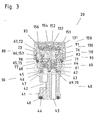
- Fig. 3 shows the structure of the elastomeric membrane breather 20 in a sectional view.
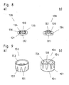
- the main body 60 of the valve core 30 - Fig. 5 - is - like the insert 40 - Fig. 4 - Is substantially hollow cylindrical shape 61 , is integrally releasably latched with the insert 45, 46, 62, has both at its lower and at its upper end depending on an external thread 1, 2 64, 66 with an intermediate, a further sealing ring 2 65 supporting Groove 75.
- This lower external thread 1 64 corresponds to the internal thread 15 of the central middle part 14 of the T-fitting 10; screwed seals the sealing ring 2 65 from the inside space between insert and center piece.
- the upper threads 66 form the releasable connection to the internal thread 153 of the lid 150 .
- the tubular 2-channel continuation of the insert 47 in the body is filled with a spiralfedergelagertem ball valve 70, 71 , wherein the valve springs 70 are supported on the one hand on the tubular projections 47 of the insert and on the other hand against two, each as a pronounced ram 92 pin of the lid insert 90 guided valve balls 71 press. These two ball valves then close the two hitherto separate channels 68 , 69 - to prevent leakage of the heating medium - when the vent attachment 80 is removed for maintenance or repair.
- an intermediate disc 130 is releasably engaged via latched on the disc latching hooks 132 ; the washer has around the center through holes for the vent 133 and in the edge zones radial slots 134 for receiving corresponding locking hooks 93 of the lid insert 90 .
- Lid, washer and lid insert are substantially cylindrical body 91 , 131 151; each half-sided axial recesses 95, 135 between the slots 134 on the underside of the washer and between the locking hooks 93 on the top of the lid insert 90 create a disc-shaped space for receiving the elasto-mergespritzten semipermeable membrane 110 as an insert 111th
- axial through holes 94 are provided as channel A, B in height of the membrane of the Dekkelencieses.
- vent cap 80 To ensure that the degassing of the heating medium takes place without exception through the holes of the lid insert and washer and semipermeable mem bran, the vent cap 80 must otherwise have a very good tightness; this is promoted by the edge 112 and transverse reinforcement 113 of the membrane or taking into account at the recesses 95, 135th
- an approximately hollow cylindrical seal 3 76 is fitted in the axial direction; this seal defined in the installed state of the lid insert with the body the way of the heating medium through the axial through holes 94 of the lid insert to the semipermeable membrane 110 and ensures the tightness of the breather 20 safely.
- the cylindrical disposition of the latching hook 132 of the intermediate disk 130 inserted into the cover bore 154 under tension takes up the hollow-cylindrical clamping device of the decorative cover 152 .
- the valve insert consisting of body and insert is tight and tight with the central center of the T-fitting screwed.
- the axially displaceable lid insert has two diametrically arranged oval projections 99, which are guided in corresponding recesses 74 of the body and ensure anti-rotation.
- the intermediate disc has arranged in the edge zones radial slots 134 for receiving corresponding latching hooks 93 of the lid insert, said compound tolerates no rotational movement, which also applies to the introduced in the space between the two components 95, 135 semipermeable membrane - grooves 97 , 136 each half Diameter take the transverse reinforcement 113 of the diaphragm positionally correct and against rotation.
- the heating medium flows through the two opposite supply / return connection pieces 11 , 12 of the T-fitting 10 in the central centerpiece 13, 14, there over the two channels A, B 42 , 43 of the insert 40 and the channels A, B 68, 69 of the base body 60 to the ball valves 70, 71, via the opened by the plunger 92 of the lid insert 90 ball valves through the holes 94 of the lid insert to the semipermeable membrane 110 for degassing via the gas channel 133, 155.
Priority Applications (1)
| Application Number | Priority Date | Filing Date | Title |
|---|---|---|---|
| PL15000978T PL2988043T3 (pl) | 2014-08-11 | 2015-04-07 | Złączka z odpowietrznikiem z membraną elastomerową |
Applications Claiming Priority (1)
| Application Number | Priority Date | Filing Date | Title |
|---|---|---|---|
| DE202014006323.0U DE202014006323U1 (de) | 2014-08-11 | 2014-08-11 | Anschlußstück mit Elastomermembran-Entlüfter 2 |
Publications (2)
| Publication Number | Publication Date |
|---|---|
| EP2988043A1 true EP2988043A1 (fr) | 2016-02-24 |
| EP2988043B1 EP2988043B1 (fr) | 2018-03-07 |
Family
ID=51618781
Family Applications (1)
| Application Number | Title | Priority Date | Filing Date |
|---|---|---|---|
| EP15000978.5A Active EP2988043B1 (fr) | 2014-08-11 | 2015-04-07 | Pièce de raccordement avec ventilateur à membrane élastomère |
Country Status (4)
| Country | Link |
|---|---|
| EP (1) | EP2988043B1 (fr) |
| DE (1) | DE202014006323U1 (fr) |
| DK (1) | DK2988043T3 (fr) |
| PL (1) | PL2988043T3 (fr) |
Families Citing this family (4)
| Publication number | Priority date | Publication date | Assignee | Title |
|---|---|---|---|---|
| DE102015004532B3 (de) * | 2015-04-02 | 2016-09-29 | Capricorn S. A. | Belüftungsventil für ein Kanalisationsrohr |
| DE102019103431B3 (de) * | 2019-02-12 | 2020-04-09 | Hugo Benzing Gmbh & Co. Kg | Druckentlastungsventil zum Abbau von in einem zellenartigen Hohlraum, wie einer Batteriezelle, entstehendem Druck |
| CN110566703B (zh) * | 2019-10-09 | 2024-04-19 | 西安广核阀门科技有限公司 | 一种低温精密调压阀 |
| DE102020116127A1 (de) | 2020-06-18 | 2021-12-23 | Rahrbach Gmbh | Verriegelungsvorrichtung mit Entlüftungskanal |
Citations (21)
| Publication number | Priority date | Publication date | Assignee | Title |
|---|---|---|---|---|
| DE2208204A1 (de) | 1971-02-22 | 1972-09-07 | Vychoodoslovenske zheleziarne, N.P., Koshice (Tschechoslowakei) | Anschlußstück für einen zweireihigen Heizkörper |
| DE7802144U1 (de) | 1978-01-25 | 1978-07-13 | Buedinger Metallwarenfabrik Linn & Lange Gmbh, 6470 Buedingen | Anschlusstueck fuer heizkoerper |
| DE7802277U1 (de) | 1978-01-26 | 1978-07-20 | Buedinger Metallwarenfabrik Linn & Lange Gmbh, 6470 Buedingen | Anschlusstueck fuer heizkoerper |
| DE2803363A1 (de) | 1978-01-26 | 1979-08-02 | Buedinger Metallwarenfab Linn | Anschlusstueck fuer heizkoerper und verfahren zu seiner herstellung |
| ES2025436A6 (es) | 1990-06-28 | 1992-03-16 | Manaut S A | Racord monopieza perfeccionado, para paneles radiadores de calefaccion. |
| DE29500101U1 (de) | 1995-01-04 | 1995-03-02 | Thermo Technik Buedingen Gmbh | Anschlußelement für einen Heizkörper |
| DE19614330C1 (de) | 1996-04-11 | 1997-03-13 | Oventrop Sohn Kg F W | Mehrlagiger Plattenheizkörper mit integrierter Ventilgarnitur |
| DE20104315U1 (de) | 2001-03-13 | 2001-05-23 | Koenig Christel | Anschlußteil für einen Heizkörper sowie Heizkörperanordnung |
| WO2003008849A1 (fr) * | 2001-07-18 | 2003-01-30 | National Oilwell Norway As | Dispositif de clapet de retenue multibilles |
| DE20313142U1 (de) * | 2003-08-22 | 2003-12-24 | Bohatsch, Axel | Vorrichtung zum Steuern der Luftzirkulation in einem Abwasserschacht |
| DE202004001139U1 (de) * | 2004-01-27 | 2004-04-01 | Rabe, Wolfgang | Druckausgleichselement |
| DE102006021454A1 (de) * | 2006-04-01 | 2007-12-06 | Hidde, Axel R., Dr. Ing. | Be- und Entlüftungsautomat mit Membran |
| DE202009007149U1 (de) | 2009-05-18 | 2010-10-14 | Caradon Heating Europe B.V. | Anschlussteil einer Heizplatte eines Heizkörpers sowie Plattenheizkörper |
| DE102009048402A1 (de) | 2009-10-06 | 2011-04-07 | Wilhelm Schauerte Gmbh & Co. Kg | Be- und Entlüftungsautomat mit Membran als Systembaukasten |
| DE202011109189U1 (de) | 2011-12-19 | 2012-02-03 | Wilhelm Schauerte Gmbh & Co. Kg | Anschlußstück mit Elastomermembran-Entlüfter |
| DE102010051890A1 (de) | 2010-11-22 | 2012-05-24 | Wilhelm Schauerte Gmbh & Co. Kg | Be-/Entlüftungsautomat mit Elasto-mer-Membran |
| DE102010055886A1 (de) | 2010-12-25 | 2012-06-28 | Wilhelm Schauerte Gmbh & Co. Kg | Be-/Entlüftungsautomat mit Elastomer-Membran 2 |
| EP2525121A1 (fr) | 2011-05-19 | 2012-11-21 | Caradon Stelrad B.V. | Élément de garniture de soupape |
| DE102011050475A1 (de) | 2011-05-19 | 2012-11-22 | Caradon Stelrad B.V. | Ventileinsatzelement |
| DE102011109164A1 (de) | 2011-08-03 | 2013-02-07 | Axel R. Hidde | Luft- und Schmutzabscheider mit Elastomermembran-Entlüfter |
| DE102012100433A1 (de) | 2012-01-19 | 2013-07-25 | Caradon Stelrad B.V. | Ventileinsatzelement |
Family Cites Families (1)
| Publication number | Priority date | Publication date | Assignee | Title |
|---|---|---|---|---|
| DE1066722B (fr) | 1959-10-08 |
-
2014
- 2014-08-11 DE DE202014006323.0U patent/DE202014006323U1/de not_active Expired - Lifetime
-
2015
- 2015-04-07 EP EP15000978.5A patent/EP2988043B1/fr active Active
- 2015-04-07 PL PL15000978T patent/PL2988043T3/pl unknown
- 2015-04-07 DK DK15000978.5T patent/DK2988043T3/en active
Patent Citations (24)
| Publication number | Priority date | Publication date | Assignee | Title |
|---|---|---|---|---|
| DE2208204A1 (de) | 1971-02-22 | 1972-09-07 | Vychoodoslovenske zheleziarne, N.P., Koshice (Tschechoslowakei) | Anschlußstück für einen zweireihigen Heizkörper |
| DE7802144U1 (de) | 1978-01-25 | 1978-07-13 | Buedinger Metallwarenfabrik Linn & Lange Gmbh, 6470 Buedingen | Anschlusstueck fuer heizkoerper |
| DE7802277U1 (de) | 1978-01-26 | 1978-07-20 | Buedinger Metallwarenfabrik Linn & Lange Gmbh, 6470 Buedingen | Anschlusstueck fuer heizkoerper |
| DE2803363A1 (de) | 1978-01-26 | 1979-08-02 | Buedinger Metallwarenfab Linn | Anschlusstueck fuer heizkoerper und verfahren zu seiner herstellung |
| ES2025436A6 (es) | 1990-06-28 | 1992-03-16 | Manaut S A | Racord monopieza perfeccionado, para paneles radiadores de calefaccion. |
| DE29500101U1 (de) | 1995-01-04 | 1995-03-02 | Thermo Technik Buedingen Gmbh | Anschlußelement für einen Heizkörper |
| DE29503555U1 (de) | 1995-01-04 | 1995-05-18 | Koenig Christel | Anschlußelement für einen Heizkörper |
| DE19614330C1 (de) | 1996-04-11 | 1997-03-13 | Oventrop Sohn Kg F W | Mehrlagiger Plattenheizkörper mit integrierter Ventilgarnitur |
| DE20104315U1 (de) | 2001-03-13 | 2001-05-23 | Koenig Christel | Anschlußteil für einen Heizkörper sowie Heizkörperanordnung |
| EP1249285A2 (fr) | 2001-03-13 | 2002-10-16 | Christel König | Procédé de fabrication d'un raccord pour un radiateur de chauffage ainsi que radiateur de chauffage |
| WO2003008849A1 (fr) * | 2001-07-18 | 2003-01-30 | National Oilwell Norway As | Dispositif de clapet de retenue multibilles |
| DE20313142U1 (de) * | 2003-08-22 | 2003-12-24 | Bohatsch, Axel | Vorrichtung zum Steuern der Luftzirkulation in einem Abwasserschacht |
| DE202004001139U1 (de) * | 2004-01-27 | 2004-04-01 | Rabe, Wolfgang | Druckausgleichselement |
| DE102006021454A1 (de) * | 2006-04-01 | 2007-12-06 | Hidde, Axel R., Dr. Ing. | Be- und Entlüftungsautomat mit Membran |
| DE202009007149U1 (de) | 2009-05-18 | 2010-10-14 | Caradon Heating Europe B.V. | Anschlussteil einer Heizplatte eines Heizkörpers sowie Plattenheizkörper |
| DE102009048402A1 (de) | 2009-10-06 | 2011-04-07 | Wilhelm Schauerte Gmbh & Co. Kg | Be- und Entlüftungsautomat mit Membran als Systembaukasten |
| DE102010051890A1 (de) | 2010-11-22 | 2012-05-24 | Wilhelm Schauerte Gmbh & Co. Kg | Be-/Entlüftungsautomat mit Elasto-mer-Membran |
| DE102010055886A1 (de) | 2010-12-25 | 2012-06-28 | Wilhelm Schauerte Gmbh & Co. Kg | Be-/Entlüftungsautomat mit Elastomer-Membran 2 |
| EP2525121A1 (fr) | 2011-05-19 | 2012-11-21 | Caradon Stelrad B.V. | Élément de garniture de soupape |
| DE102011050475A1 (de) | 2011-05-19 | 2012-11-22 | Caradon Stelrad B.V. | Ventileinsatzelement |
| DE102011109164A1 (de) | 2011-08-03 | 2013-02-07 | Axel R. Hidde | Luft- und Schmutzabscheider mit Elastomermembran-Entlüfter |
| DE202011109189U1 (de) | 2011-12-19 | 2012-02-03 | Wilhelm Schauerte Gmbh & Co. Kg | Anschlußstück mit Elastomermembran-Entlüfter |
| EP2607798A2 (fr) | 2011-12-19 | 2013-06-26 | Wilhelm Schauerte GmbH & Co. KG Geschäftsführung | Pièce de raccordement avec désaérateur à membrane élastomère |
| DE102012100433A1 (de) | 2012-01-19 | 2013-07-25 | Caradon Stelrad B.V. | Ventileinsatzelement |
Also Published As
| Publication number | Publication date |
|---|---|
| DK2988043T3 (en) | 2018-04-23 |
| EP2988043B1 (fr) | 2018-03-07 |
| DE202014006323U1 (de) | 2014-09-05 |
| PL2988043T3 (pl) | 2018-07-31 |
Similar Documents
| Publication | Publication Date | Title |
|---|---|---|
| EP2988043B1 (fr) | Pièce de raccordement avec ventilateur à membrane élastomère | |
| DE4128153A1 (de) | Scheibenoelkuehler | |
| DE2312520A1 (de) | Ventilpatrone fuer wasserhaehne o.dgl | |
| EP1696158A1 (fr) | Tête de robinet | |
| DE102008056245A1 (de) | Thermostatventil | |
| EP1655551A2 (fr) | Raccord pour deux plaques d'un radiateur et radiateur | |
| WO2013034757A1 (fr) | Robinet de lavabo sanitaire à levier unique | |
| EP3037699B1 (fr) | Vanne mélangeuse | |
| EP1728541A1 (fr) | Element filtrant pour filtre a liquide | |
| DE102013200533B4 (de) | Ventilpatrone | |
| DE2829216C2 (de) | Heizmittelverteiler | |
| EP1376289A1 (fr) | Dispositif de commande de pression | |
| EP0458076B1 (fr) | Distributeur pour branchement de tuyaux parcourus par au moins un fluide | |
| DE19713953A1 (de) | Armatur zum Anschluß eines Heizkörpers an die Zulauf- und Rücklaufrohrleitungen einer Zweirohrheizanlage | |
| DE202011109189U1 (de) | Anschlußstück mit Elastomermembran-Entlüfter | |
| DE19854848A1 (de) | Anschlußeinrichtung für Heizkörper | |
| EP1367306A1 (fr) | Cartouche de soupape | |
| WO2012084296A1 (fr) | Corps de boîtier de soupape | |
| DE19647026A1 (de) | Heizkörperventil | |
| EP4058638B1 (fr) | Robinetterie sanitaire | |
| EP3822420B1 (fr) | Un robinet de mélangeur et un système de raccordement, destinés à l'utilisation comme robinetterie haute pression ou basse pression | |
| DE202018000709U1 (de) | Be-/Entlüftungsautomat mit Hand-/Schnellentlüftung | |
| DE4305694A1 (de) | Verteileraggregat für mit einem strömungsfähigen Wärmeträgermedium arbeitende Heiz- oder Kühlanlagen | |
| EP3467212B1 (fr) | Robinetterie sanitaire | |
| EP1632702B1 (fr) | Robinet mitigeur |
Legal Events
| Date | Code | Title | Description |
|---|---|---|---|
| PUAI | Public reference made under article 153(3) epc to a published international application that has entered the european phase |
Free format text: ORIGINAL CODE: 0009012 |
|
| AK | Designated contracting states |
Kind code of ref document: A1 Designated state(s): AL AT BE BG CH CY CZ DE DK EE ES FI FR GB GR HR HU IE IS IT LI LT LU LV MC MK MT NL NO PL PT RO RS SE SI SK SM TR |
|
| AX | Request for extension of the european patent |
Extension state: BA ME |
|
| 17P | Request for examination filed |
Effective date: 20160422 |
|
| RBV | Designated contracting states (corrected) |
Designated state(s): AL AT BE BG CH CY CZ DE DK EE ES FI FR GB GR HR HU IE IS IT LI LT LU LV MC MK MT NL NO PL PT RO RS SE SI SK SM TR |
|
| GRAP | Despatch of communication of intention to grant a patent |
Free format text: ORIGINAL CODE: EPIDOSNIGR1 |
|
| RIC1 | Information provided on ipc code assigned before grant |
Ipc: F16K 24/04 20060101AFI20171114BHEP Ipc: F24D 19/08 20060101ALI20171114BHEP Ipc: B01D 19/00 20060101ALI20171114BHEP |
|
| GRAS | Grant fee paid |
Free format text: ORIGINAL CODE: EPIDOSNIGR3 |
|
| INTG | Intention to grant announced |
Effective date: 20171220 |
|
| GRAA | (expected) grant |
Free format text: ORIGINAL CODE: 0009210 |
|
| AK | Designated contracting states |
Kind code of ref document: B1 Designated state(s): AL AT BE BG CH CY CZ DE DK EE ES FI FR GB GR HR HU IE IS IT LI LT LU LV MC MK MT NL NO PL PT RO RS SE SI SK SM TR |
|
| REG | Reference to a national code |
Ref country code: GB Ref legal event code: FG4D Free format text: NOT ENGLISH |
|
| REG | Reference to a national code |
Ref country code: CH Ref legal event code: EP Ref country code: AT Ref legal event code: REF Ref document number: 976926 Country of ref document: AT Kind code of ref document: T Effective date: 20180315 |
|
| REG | Reference to a national code |
Ref country code: FR Ref legal event code: PLFP Year of fee payment: 4 |
|
| REG | Reference to a national code |
Ref country code: IE Ref legal event code: FG4D Free format text: LANGUAGE OF EP DOCUMENT: GERMAN |
|
| REG | Reference to a national code |
Ref country code: DE Ref legal event code: R096 Ref document number: 502015003268 Country of ref document: DE |
|
| REG | Reference to a national code |
Ref country code: DK Ref legal event code: T3 Effective date: 20180420 |
|
| REG | Reference to a national code |
Ref country code: SE Ref legal event code: TRGR |
|
| REG | Reference to a national code |
Ref country code: NL Ref legal event code: FP |
|
| REG | Reference to a national code |
Ref country code: LT Ref legal event code: MG4D |
|
| PG25 | Lapsed in a contracting state [announced via postgrant information from national office to epo] |
Ref country code: FI Free format text: LAPSE BECAUSE OF FAILURE TO SUBMIT A TRANSLATION OF THE DESCRIPTION OR TO PAY THE FEE WITHIN THE PRESCRIBED TIME-LIMIT Effective date: 20180307 Ref country code: NO Free format text: LAPSE BECAUSE OF FAILURE TO SUBMIT A TRANSLATION OF THE DESCRIPTION OR TO PAY THE FEE WITHIN THE PRESCRIBED TIME-LIMIT Effective date: 20180607 Ref country code: CY Free format text: LAPSE BECAUSE OF FAILURE TO SUBMIT A TRANSLATION OF THE DESCRIPTION OR TO PAY THE FEE WITHIN THE PRESCRIBED TIME-LIMIT Effective date: 20180307 Ref country code: LT Free format text: LAPSE BECAUSE OF FAILURE TO SUBMIT A TRANSLATION OF THE DESCRIPTION OR TO PAY THE FEE WITHIN THE PRESCRIBED TIME-LIMIT Effective date: 20180307 Ref country code: HR Free format text: LAPSE BECAUSE OF FAILURE TO SUBMIT A TRANSLATION OF THE DESCRIPTION OR TO PAY THE FEE WITHIN THE PRESCRIBED TIME-LIMIT Effective date: 20180307 Ref country code: ES Free format text: LAPSE BECAUSE OF FAILURE TO SUBMIT A TRANSLATION OF THE DESCRIPTION OR TO PAY THE FEE WITHIN THE PRESCRIBED TIME-LIMIT Effective date: 20180307 |
|
| PG25 | Lapsed in a contracting state [announced via postgrant information from national office to epo] |
Ref country code: BG Free format text: LAPSE BECAUSE OF FAILURE TO SUBMIT A TRANSLATION OF THE DESCRIPTION OR TO PAY THE FEE WITHIN THE PRESCRIBED TIME-LIMIT Effective date: 20180607 Ref country code: GR Free format text: LAPSE BECAUSE OF FAILURE TO SUBMIT A TRANSLATION OF THE DESCRIPTION OR TO PAY THE FEE WITHIN THE PRESCRIBED TIME-LIMIT Effective date: 20180608 Ref country code: LV Free format text: LAPSE BECAUSE OF FAILURE TO SUBMIT A TRANSLATION OF THE DESCRIPTION OR TO PAY THE FEE WITHIN THE PRESCRIBED TIME-LIMIT Effective date: 20180307 Ref country code: RS Free format text: LAPSE BECAUSE OF FAILURE TO SUBMIT A TRANSLATION OF THE DESCRIPTION OR TO PAY THE FEE WITHIN THE PRESCRIBED TIME-LIMIT Effective date: 20180307 |
|
| PG25 | Lapsed in a contracting state [announced via postgrant information from national office to epo] |
Ref country code: MT Free format text: LAPSE BECAUSE OF FAILURE TO SUBMIT A TRANSLATION OF THE DESCRIPTION OR TO PAY THE FEE WITHIN THE PRESCRIBED TIME-LIMIT Effective date: 20180307 |
|
| PG25 | Lapsed in a contracting state [announced via postgrant information from national office to epo] |
Ref country code: RO Free format text: LAPSE BECAUSE OF FAILURE TO SUBMIT A TRANSLATION OF THE DESCRIPTION OR TO PAY THE FEE WITHIN THE PRESCRIBED TIME-LIMIT Effective date: 20180307 Ref country code: EE Free format text: LAPSE BECAUSE OF FAILURE TO SUBMIT A TRANSLATION OF THE DESCRIPTION OR TO PAY THE FEE WITHIN THE PRESCRIBED TIME-LIMIT Effective date: 20180307 Ref country code: AL Free format text: LAPSE BECAUSE OF FAILURE TO SUBMIT A TRANSLATION OF THE DESCRIPTION OR TO PAY THE FEE WITHIN THE PRESCRIBED TIME-LIMIT Effective date: 20180307 |
|
| PG25 | Lapsed in a contracting state [announced via postgrant information from national office to epo] |
Ref country code: SK Free format text: LAPSE BECAUSE OF FAILURE TO SUBMIT A TRANSLATION OF THE DESCRIPTION OR TO PAY THE FEE WITHIN THE PRESCRIBED TIME-LIMIT Effective date: 20180307 Ref country code: SM Free format text: LAPSE BECAUSE OF FAILURE TO SUBMIT A TRANSLATION OF THE DESCRIPTION OR TO PAY THE FEE WITHIN THE PRESCRIBED TIME-LIMIT Effective date: 20180307 |
|
| REG | Reference to a national code |
Ref country code: DE Ref legal event code: R097 Ref document number: 502015003268 Country of ref document: DE |
|
| PG25 | Lapsed in a contracting state [announced via postgrant information from national office to epo] |
Ref country code: PT Free format text: LAPSE BECAUSE OF FAILURE TO SUBMIT A TRANSLATION OF THE DESCRIPTION OR TO PAY THE FEE WITHIN THE PRESCRIBED TIME-LIMIT Effective date: 20180709 |
|
| PLBE | No opposition filed within time limit |
Free format text: ORIGINAL CODE: 0009261 |
|
| STAA | Information on the status of an ep patent application or granted ep patent |
Free format text: STATUS: NO OPPOSITION FILED WITHIN TIME LIMIT |
|
| REG | Reference to a national code |
Ref country code: IE Ref legal event code: MM4A |
|
| PG25 | Lapsed in a contracting state [announced via postgrant information from national office to epo] |
Ref country code: MC Free format text: LAPSE BECAUSE OF FAILURE TO SUBMIT A TRANSLATION OF THE DESCRIPTION OR TO PAY THE FEE WITHIN THE PRESCRIBED TIME-LIMIT Effective date: 20180307 |
|
| 26N | No opposition filed |
Effective date: 20181210 |
|
| PG25 | Lapsed in a contracting state [announced via postgrant information from national office to epo] |
Ref country code: SI Free format text: LAPSE BECAUSE OF FAILURE TO SUBMIT A TRANSLATION OF THE DESCRIPTION OR TO PAY THE FEE WITHIN THE PRESCRIBED TIME-LIMIT Effective date: 20180307 |
|
| PG25 | Lapsed in a contracting state [announced via postgrant information from national office to epo] |
Ref country code: IE Free format text: LAPSE BECAUSE OF NON-PAYMENT OF DUE FEES Effective date: 20180407 |
|
| PGFP | Annual fee paid to national office [announced via postgrant information from national office to epo] |
Ref country code: GB Payment date: 20190130 Year of fee payment: 5 Ref country code: CZ Payment date: 20190320 Year of fee payment: 5 Ref country code: LU Payment date: 20190325 Year of fee payment: 5 Ref country code: GB Payment date: 20190320 Year of fee payment: 5 Ref country code: PL Payment date: 20190320 Year of fee payment: 5 |
|
| PGFP | Annual fee paid to national office [announced via postgrant information from national office to epo] |
Ref country code: SE Payment date: 20190320 Year of fee payment: 5 |
|
| PG25 | Lapsed in a contracting state [announced via postgrant information from national office to epo] |
Ref country code: TR Free format text: LAPSE BECAUSE OF FAILURE TO SUBMIT A TRANSLATION OF THE DESCRIPTION OR TO PAY THE FEE WITHIN THE PRESCRIBED TIME-LIMIT Effective date: 20180307 |
|
| PG25 | Lapsed in a contracting state [announced via postgrant information from national office to epo] |
Ref country code: MK Free format text: LAPSE BECAUSE OF NON-PAYMENT OF DUE FEES Effective date: 20180307 Ref country code: HU Free format text: LAPSE BECAUSE OF FAILURE TO SUBMIT A TRANSLATION OF THE DESCRIPTION OR TO PAY THE FEE WITHIN THE PRESCRIBED TIME-LIMIT; INVALID AB INITIO Effective date: 20150407 |
|
| PG25 | Lapsed in a contracting state [announced via postgrant information from national office to epo] |
Ref country code: IS Free format text: LAPSE BECAUSE OF FAILURE TO SUBMIT A TRANSLATION OF THE DESCRIPTION OR TO PAY THE FEE WITHIN THE PRESCRIBED TIME-LIMIT Effective date: 20180707 |
|
| PGFP | Annual fee paid to national office [announced via postgrant information from national office to epo] |
Ref country code: CH Payment date: 20200406 Year of fee payment: 6 |
|
| PGFP | Annual fee paid to national office [announced via postgrant information from national office to epo] |
Ref country code: IT Payment date: 20200406 Year of fee payment: 6 |
|
| PG25 | Lapsed in a contracting state [announced via postgrant information from national office to epo] |
Ref country code: CZ Free format text: LAPSE BECAUSE OF NON-PAYMENT OF DUE FEES Effective date: 20200407 |
|
| REG | Reference to a national code |
Ref country code: DK Ref legal event code: EBP Effective date: 20200430 |
|
| PG25 | Lapsed in a contracting state [announced via postgrant information from national office to epo] |
Ref country code: SE Free format text: LAPSE BECAUSE OF NON-PAYMENT OF DUE FEES Effective date: 20200408 Ref country code: FR Free format text: LAPSE BECAUSE OF NON-PAYMENT OF DUE FEES Effective date: 20200430 Ref country code: LU Free format text: LAPSE BECAUSE OF NON-PAYMENT OF DUE FEES Effective date: 20200407 |
|
| GBPC | Gb: european patent ceased through non-payment of renewal fee |
Effective date: 20200407 |
|
| PG25 | Lapsed in a contracting state [announced via postgrant information from national office to epo] |
Ref country code: GB Free format text: LAPSE BECAUSE OF NON-PAYMENT OF DUE FEES Effective date: 20200407 Ref country code: DK Free format text: LAPSE BECAUSE OF NON-PAYMENT OF DUE FEES Effective date: 20200430 |
|
| PG25 | Lapsed in a contracting state [announced via postgrant information from national office to epo] |
Ref country code: LI Free format text: LAPSE BECAUSE OF NON-PAYMENT OF DUE FEES Effective date: 20210430 Ref country code: CH Free format text: LAPSE BECAUSE OF NON-PAYMENT OF DUE FEES Effective date: 20210430 |
|
| PG25 | Lapsed in a contracting state [announced via postgrant information from national office to epo] |
Ref country code: PL Free format text: LAPSE BECAUSE OF NON-PAYMENT OF DUE FEES Effective date: 20200407 |
|
| PG25 | Lapsed in a contracting state [announced via postgrant information from national office to epo] |
Ref country code: IT Free format text: LAPSE BECAUSE OF NON-PAYMENT OF DUE FEES Effective date: 20200407 |
|
| PGFP | Annual fee paid to national office [announced via postgrant information from national office to epo] |
Ref country code: NL Payment date: 20230430 Year of fee payment: 9 Ref country code: DE Payment date: 20230502 Year of fee payment: 9 |
|
| PGFP | Annual fee paid to national office [announced via postgrant information from national office to epo] |
Ref country code: AT Payment date: 20230502 Year of fee payment: 9 |
|
| PGFP | Annual fee paid to national office [announced via postgrant information from national office to epo] |
Ref country code: BE Payment date: 20230501 Year of fee payment: 9 |