EP2988043A1 - Connecting piece with elastomer membrane vent - Google Patents
Connecting piece with elastomer membrane vent Download PDFInfo
- Publication number
- EP2988043A1 EP2988043A1 EP15000978.5A EP15000978A EP2988043A1 EP 2988043 A1 EP2988043 A1 EP 2988043A1 EP 15000978 A EP15000978 A EP 15000978A EP 2988043 A1 EP2988043 A1 EP 2988043A1
- Authority
- EP
- European Patent Office
- Prior art keywords
- insert
- connecting piece
- piece
- central
- lid
- Prior art date
- Legal status (The legal status is an assumption and is not a legal conclusion. Google has not performed a legal analysis and makes no representation as to the accuracy of the status listed.)
- Granted
Links
Images


Classifications
-
- F—MECHANICAL ENGINEERING; LIGHTING; HEATING; WEAPONS; BLASTING
- F16—ENGINEERING ELEMENTS AND UNITS; GENERAL MEASURES FOR PRODUCING AND MAINTAINING EFFECTIVE FUNCTIONING OF MACHINES OR INSTALLATIONS; THERMAL INSULATION IN GENERAL
- F16K—VALVES; TAPS; COCKS; ACTUATING-FLOATS; DEVICES FOR VENTING OR AERATING
- F16K24/00—Devices, e.g. valves, for venting or aerating enclosures
- F16K24/04—Devices, e.g. valves, for venting or aerating enclosures for venting only
-
- B—PERFORMING OPERATIONS; TRANSPORTING
- B01—PHYSICAL OR CHEMICAL PROCESSES OR APPARATUS IN GENERAL
- B01D—SEPARATION
- B01D19/00—Degasification of liquids
- B01D19/0031—Degasification of liquids by filtration
-
- F—MECHANICAL ENGINEERING; LIGHTING; HEATING; WEAPONS; BLASTING
- F24—HEATING; RANGES; VENTILATING
- F24D—DOMESTIC- OR SPACE-HEATING SYSTEMS, e.g. CENTRAL HEATING SYSTEMS; DOMESTIC HOT-WATER SUPPLY SYSTEMS; ELEMENTS OR COMPONENTS THEREFOR
- F24D19/00—Details
- F24D19/08—Arrangements for drainage, venting or aerating
Definitions
- the invention relates to a fitting with further functions for a water technical device - in particular a 3-way or T-fitting with an elastomeric membrane breather.
- connection devices and fittings are required in the installation technology in water technical systems such as sanitary facilities, hot water and heating systems in many forms. Piping transitions require couplings and couplings, pipe diameter changes require reducers, pipe branches require tees, and piping connections and piping connections are made by fittings.
- the number of subsequent devices to such connectors is as varied as the number of line inputs and outputs. In the present case, it is an example of a line inlet and outlet as well as the connection or the connection to / to an elastomeric membrane breather.
- a T-shaped fitting for heating systems is presented, with an approximately at the outlet for the heat consumer to be connected in the main flow direction obliquely arranged baffle for the hot water.
- Such deflections have already been introduced in a stepped form in the tee with the disadvantage of uneven flow and vortex formation.
- a cylindrical hollow body is introduced in the main flow direction, the outgoing surface of which forms the sector of a conical surface, which kinks at the upper end in the main flow direction and on both sides down to one with the inner circumference of the main pipe approximately matching, in Main flow direction is complemented on both sides open hollow body.
- the main stream is divided at the beginning of the baffle in three sub-streams - the flowing part of the main stream, diverted to the departure partial flow and flowing through a remaining small channel dam and vortex preventing partial flow in the main flow direction.
- the dimensioning of the baffle already causes problems that meet the calculated non-adjustable body completely different heat demand-dependent flows;
- the partial flow diverted to the outlet is also dependent on the local local heat demand.
- the production of the body and its position-appropriate permanent introduction into the T-piece are expensive.
- a controlling valve arrangement is not provided.
- the publication DE 22 08 204 treated a fitting for a double-row radiator peculiarity that the connector according to the invention over the commercial T-piece can shrink the distance between two parallel radiator plates by approximately half.
- the T-piece provides for the installation of the heating flow the connection of an actuating valve and the introduction of a vent valve in the hotplate connection head.
- the plate distance reduction is achieved on the one hand by changing the terminal profile of the T-piece in a rectangular profile for Schwarzplattenmontage and on the other hand by considerable depth reduction of the Schuplatten connection thread.
- the change in profile has a volume-reducing and possibly noise-reducing effect on the water flow, in any case, strong turbulence is expected at the transition point.
- the greatly reduced hotplate connection thread requires the radiator also shortened union nuts for connection, which means an increase in the variety of types.
- the fitting does not allow a serial filling of the radiator plates; the venting valve in the connection head can only ventilate both heating plates at the same time.
- German disclosure DE 28 03 363 / utility model DE 78 02 277 and utility models DE 78 02 144 disclose a connecting piece for the connection of a line leading the heating medium to one, preferably two-layer radiator, wherein the connecting piece consists of a connection to the heating plate (s) certain connection part and a welded thereto, for connection to the line of the heating medium certain connection part, wherein the connecting part is continuously made of a cylindrical piece of pipe, that in the lateral surface thereof a cutout is provided and that the connecting part has at one of its ends end edges of such a shape that they are surrounding the cutout, fed on the pipe section resting thereon welded or that on the end face (s) of the connecting part, a solder joint is welded.
- the publications are devoted to the manufacturing process of T-shaped fittings; No indication of system technology with ventilation.
- the Spanish application ES 2 025 436 shows a one-piece connection for flow / inlet and return / drain radiator plates, exemplified executed in L and T shape.
- the outgoing side is dual-channeled and on the input side the riser pipe forms a channel and, outside the riser pipe, the second channel is arranged.
- the center port on two baffles which serve the one-piece recording of the riser, so that the medium is passed on the one hand via an inlet side of the fitting in the riser and on the other hand, the channel between the riser and center port as a drain on the second, the drain side of the connector leads.
- the T-fitting design can also be used to some extent for the development of such a vent valve; in the publication, the ventilation is not considered.
- connection element for a radiator, which are needed especially for flat or plate radiators for connecting heating plates with flow and return lines or with a control valve.
- flat radiators in particular L- or T-shaped connecting pipe pieces are used. These connecting pipe pieces are welded on the one hand to the radiator, creating a dense and mechanically stable connection; For connection to the piping is often provided a threaded connection. It is proposed to carry out the connection element as a plastic molded part with at least one metal insert firmly connected thereto; No specifications are made about the assignment of the connections.
- the German patent DE 196 14 330 presents a multi-layer panel radiator or a group with integrated valve set for inlet, outlet, valve control and ventilation such that the radiator inlet and outlet are connected on the bottom side with the Schuvorvor- and return that the two plates or plate groups trained only as a valve Connecting piece at the upper, the bottom opposite plate end are fluidly connected and at the other upper end of the rectangular plate assembly venting devices - three variants - are provided, wherein the first, connected to the heating flow plate the flow channel and the second, connected to the return plate forms the return channel and the serial filling of the plates takes place via the valve assembly.
- a venting device provides independent ventilation from the other heater plate via one L-piece each; another variant provides a connecting the two heating plates pipe section, which has a ball valve with L-passage in its center, so that depending on the valve position by turning the functions 'Closed', 'plate 1 open' or 'plate 2 open' are set can.
- a double seat formation with a radially directed vent screw is provided in the middle of the plate-connecting pipe section; this function remains unclear, the announced separate ventilation of the plates is not given.
- the German Utility Model DE 201 04 315 / European registration EP 1 249 285 presents a method for producing a connection part - in particular for a radiator - with at least two connecting pieces, which are arranged on a center piece, in which a flow connection is provided.
- a workpiece is formed by cold extrusion into a one-piece body with a solid center piece and at least two tubular connecting pieces arranged thereon.
- As a flow connection at least one channel is introduced into the middle piece.
- the center piece accommodates various devices, such as a blind plug, valve insert or vent insert, but is not designed for continuous venting with elastomeric membrane breather.
- the connecting part has two connecting portions, each having an end-side opening cross-section and a valve portion in the end opening cross section, a valve with its connecting portion is sealingly insertable, wherein in the interior of the connecting part, a pipe section is arranged, which defines a flow channel, which opens into a connecting portion, wherein an inner circumferential surface of the connecting portion of the valve an outer circumferential surface of the pipe section or vice versa is sealingly umschbeckbar.
- the valve insert element consists of a valve body and a tubular connecting portion which connects by means of a circumferential sealing element sealingly connected to a connecting portion of the connecting part.
- the connecting portion has two circumferential sealing elements, wherein the first sealing element is arranged on a lower end side of the connecting portion and the second sealing element on a lateral surface of the connecting portion.
- a valve insert element for use in a connection tee consisting of a valve body and a connecting portion, which connects by means of a circumferential sealing member sealingly to a connecting portion of the connecting piece, wherein the sealing element viewed both along the longitudinal axis of the connecting portion axially over an end face of the Connecting portion and the same radially inwardly over an inner circumferential surface of the same and / or over an outer circumferential surface of the same projects outwardly to compensate for dimensional tolerances and as a valve insert for connecting tees with front seal.
- valve insert element can be used both for connecting parts with face-side flat cylindrical seal as well as for connecting parts with inner through-flowed pipe section, wherein the seal is made on the inner or outer circumferential surface of the pipe section.
- the dimensions of the universal valve insert element must first be dimensioned on the flat cylinder seal.
- the German utility model DE 20 2011 109 189 / European registration EP 2 607 798 describes a fitting with elastomeric membrane breather for water technical equipment, in particular for the automatic venting of serially to be filled multi-plate radiators of home and building technology.
- the 3-way or T-fitting consists of a fitting with three, lying in a plane, each offset by 90 °, emanating from a central portion of the fitting connecting piece 1, 2, 3, wherein the central connecting piece 3 through a one of transitions formed in the middle conical sealing surface unilaterally sealed, hollow cylindrical air stoppers, the medium of the connecting piece 1, 2 inside and outside the air plug separated from the middle piece leads to the outlet of the connecting piece 3, wherein the open, remote from the middle end of the connecting piece 3 carrier of a
- a selectable membrane duration vent can be connected which is fluidically connected to the venting insert or diaphragm ventilator lower part with valve functions led media.
- Entlcityerschi or Membranentlformater base is by a spring-mounted in the axial direction sealing cone, which seals one of the connector facing away from the bore, integrally connected to the sealing plunger tappet with dichtringbehaftetem valve plate which seals against the inner bore of the air plug, and by a Preßbuchse, which is supported on a connecting piece facing away from the sealing surface of the air plug with its lower circular surface and with the upper circular surface of the sealing cone facing away from the end of the spring, so as to build an axially directed force between the press bushing and sealing cone designed.
- elastomeric membrane Automatic vents with elastomeric membrane are known in the prior art and usually consist of a cover cap, an upper part, a membrane and a lower part.
- the plastic parts cover cap and upper part are sprayed in two parts, but are integrally by joining and welding, pressing and / or gluing.
- Upper and lower parts are bolted together as an insert with / without support or better with molded in the upper part in the 2K or multi-K (component) method membrane as a sealing part.
- the preferably plastic lower part also has a ball valve, which seals by means of a ball and a coil spring against a central bore in the lower part, but influenced by a plunger of the upper part, depending on the screw depth between the upper and lower part releases a gas and liquid channel.
- the lower part has - similar to a double socket - another external thread, which, provided with a sealing ring, the connection to the heating or hot water system or other closed pipe circuits forms.
- the German application 'automatic ventilation with membrane as modular system', DE 10 2009 048 402 proposes as a ventilation machine with elastomeric membrane 1 before a vent cap, which acts in conjunction with a valve body fitting as a continuous venting.
- the screw cap has a small channel / hole in the lid, which establishes the connection between the valve interior and exterior space.
- a semi-permeable membrane cartridge belongs to the scope of the device, which is positioned in the media channel and causes a positive guidance of the venting via the cartridge.
- the vent screw has inside in its center a guide pin as an opener, which acts on the spring-loaded ball seal of the check valve in dependence on the cap screwing depth and this is to open in a position. Through the semipermeable membrane gases are discharged and liquid media are retained.
- the automatic ventilation machine with elastomeric membrane 3 - German patent application DE 10 2010 055 886 - consists of a lid, a bonnet, a membrane, a base and a ball valve.
- the plastic parts cover and upper part are molded in two parts, but are integrally by joining and welding, pressing and / or gluing.
- the upper and lower parts are bolted together as a sealing part via the membrane molded in the upper part in the 2K (component) process.
- the advantage of the automatic vending machine 3 over that of the previous application is that the guidance of the liquid and gas channel is designed such that the semipermeable elastomer membrane is introduced in the 2K (component) plastic injection process during the ongoing production process.
- elastomeric membrane 4 which also consists of a lid, an adapter, a diaphragm, a lower part and a ball valve and whose function is as above.
- the adapter has an upwardly facing hole for the membrane continuous venting.
- U-shaped disk-shaped semipermeable membrane seal In a cylindrical cavity between adapter and double nipple is the integrally connected to the adapter, U-shaped disk-shaped semipermeable membrane seal. It performs an up / down movement with the left / right screw connection of cover and adapter and thus forms an open / close valve for the quick exhaust and, if necessary, via the valve tappet for the ball valve.
- the invention is therefore based on the object, a device according to the preamble of claim 1, a connecting piece with other functions for a water technical equipment - to create a 3-way or T-fitting with an elastomeric membrane breather.
- a 3-way or T-fitting is known and is used, inter alia, for connecting radiators to hot water circuits or mechanical and fluidic connection between at least two radiator plates, with a third port is at leisure, such as for connecting a thermal valve, a sealing stopper or a lockable vent insert for the purpose of constructing a valve or manifold.
- the fitting consists of a central piece and three, usually in the plane offset at right angles connecting piece, wherein the middle piece corresponding channels are provided, which are provided by transitions and sealing surfaces, and form desired open or adjustable flow connections.
- the connector for each connection piece in the middle piece has its own channel, so that influence by different applications on the central connection piece influence on the flow conditions between the channels of the two outer connecting piece can be taken.
- a further embodiment of the invention provides that the connecting piece has in its middle part a pronounced as a sealing surface, flat cylindrical transition and against which the valve stem of a valve insert or the dummy plug face of a blind terminal sealingly.
- the blind plug is designed as a vent insert to which a vent valve can be connected, through which the radiator is to vent.
- the flat cylinder transition can also be pronounced as a sealing element, depending on the material components on one or the other side of the seal.
- a further embodiment provides a sealing surface as a hollow cylindrical projection, wherein the seal is effected by means of an insert via its likewise designed as a hollow cylinder outer or inner wall corresponding. While in the flat cylindrical seal there is only a 'up' or 'to' position, the hollow cylinder solution allows depending on the height of the cylinder a travel and thus a path-dependent seal or opening with reusable valve character.
- the kit 'fitting with elastomer diaphragm vent 2' is based on a known 3-way or T-connector with a flow - channel A - and a 180 ° offset return connection piece - channel B - and another, in the Spaced by the two above-mentioned nozzle level and offset from these by 90 ° each mounted central connecting piece with a central center piece with separate channel guide, from which go out the nozzle.
- the 3-way or T-fitting is a commodity; the central center piece has a flat or an inside orpartanschsted hollow cylindrical sealing surface for the middle function terminal.
- the fitting is - as shown above - part of a commodity and is available in the version with central end seal and in the version with central hollow cylinder seal on the market.
- the components are essentially made of plastic except for the spring elements; the seals are elastomer parts.
- the plastic parts can also be made as turned or milled parts made of metal - such as brass or gunmetal.
- the components are joined in one piece to form an operational module.
- the elastomer diaphragm breather - consisting of the valve insert and venting unit assemblies - is tightly screwed into the central center piece of the T-fitting.
- sealing rings can be used as standard parts or a sealing sleeve as a structural part, which can seal both inside, front and outside. Since there are no other requirements at this point - e.g. a valve function, or similar - are set, the flat cylinder variant is the most economical solution. However, it makes sense to universally execute the connection, since both T-piece variants are performed on the market and a confusion can be excluded.
- the second inlet of the T-fitting leads - separated from the first - via a lateral inlet in the second channel of the insert;
- This space is sealed only by means of a sealing ring of the body by a screw connection between the central center piece of the T-fitting with the elastomeric membrane breather.
- the 2-channel insert is integrally tightly connected to the main body of the elastomer membrane deaerator via a mechanical separable interface; Two springs of the main body snap into the grooves of the insert over two lateral transverse grooves of the insert.
- the two symmetrically arranged, hollow cylindrical channels of the insert have at the top of each a tubular projection, each occupied by two sealing rings find their hollow cylindrical, still separate continuation in the body.
- a further advantageous embodiment of the invention provides that the base body of the valve core - as the insert - is substantially hollow cylindrical shape, is integrally releasably latched with the insert and each at its lower and at its upper end an external thread with an intermediate, another groove bearing groove has.
- This lower external thread corresponds to the internal thread of the central center of the T-fitting; screwed seals the sealing ring from the space between insert and center piece.
- the upper threads form the releasable connection to the internal thread of the lid.
- the tubular 2-channel continuation of the insert in the body is filled with a spiralfedergelagertem ball valve, the valve springs are supported on the one hand on the tubular projections of the insert and on the other hand pressed against two, each pronounced as a ram pin of the lid insert guided balls. These two ball valves then close the two hitherto separate channels - to prevent leakage of the heating medium - when the vent attachment is removed for maintenance or repair.
- lid, washer, semipermeable membrane, lid insert, seal and decorative lid form the cylindrical vent attachment on the type of the above-described automatic ventilation with semipermeable elastomeric membrane.
- an intermediate disc is releasably engaged via molded onto the disc latch hooks; the intermediate disc has through the center through holes for the vent and in the edge zones radial slots for receiving corresponding latching hooks of the lid insert.
- Lid, washer and lid insert are substantially cylindrical body; each half-sided axial recesses between the oblong holes on the underside of the washer and between the latching hooks on the top of the lid insert create a disc-shaped space for receiving the elastomergespritzten semipermeable membrane as an insert.
- a combination of washer and diaphragm or lid insert and diaphragm made in a multi-K spray process or a diaphragm insert including all three components shall also be tested.
- For the functionality of an automated venting axial through holes are also provided at the level of the membrane of the lid insert.
- the combination of lid insert, membrane and washer must withstand the system test pressure over the test time and on the other hand, the combination must be such that sufficient permeation takes place between the system and the environment. For this purpose, it is essential to ensure that the degassing of the system without exception takes place via the holes in the lid insert and washer and semi-permeable membrane, and that the ventilation attachment otherwise has a very good seal.
- a further embodiment of the invention provides that to complete the vent attachment of the lid attachment gets slipped over the underside in the axial direction an approximately hollow cylindrical seal; this seal defines in the installed state of the lid insert with the body the way of the heating medium on the axial through holes of the lid insert to the semipermeable membrane and ensures the tightness of the essay safe.
- the cylindrical release of the inserted into the cover hole locking hooks of the intermediate disc under tension on the hollow cylindrical clamping device of the decorative cover and thus secures the washer against removal or failure.
- the decorative cover adds to the appearance of the vent attachment, covers the Technique of the lid off and its visible surface is suitable for attaching promotional statements, such as proper name, manufacturer's name, type, article numbers, or similar.
- diaphragm and washer are in line with each other.
- the valve insert consisting of body and insert is firmly seated and tightly bolted to the central center piece of the T-fitting.
- the axially displaceable lid insert has two diametrically arranged oval projections, which are guided in corresponding recesses of the body and ensure anti-rotation.
- the intermediate disc has arranged in the edge zones radial slots for receiving corresponding locking hooks of the lid insert, said compound tolerates no rotational movement, which also applies to the introduced in the space between the two components semipermeable membrane.
- the heating medium flows through the two opposite connection piece of the T-fitting in the central centerpiece, where conducted over the two channels of the insert in the space between insert and body and to the ball valves, through the open ball valves through the holes in the lid insert to the semipermeable membrane for degassing.
- Points b) - c) are important for the venting of plates of flat radiators connected in series, point d) is of importance for the ventilation of parallel plates of flat radiators.
- Fig. 2 - Connector piece with elastomeric membrane breather in exploded view - is the kit 'fitting with elastomeric diaphragm breather 2' 1 on a known 3-way or T-fitting 10 with a flow connection-connection 11 - Channel A - and a 180 ° offset return connection piece 12 - channel B - and another, in the plane spanned by the two above spigot and these offset by 90 ° each mounted central connection piece 13 with a central center piece 14 with separate channel guide, from which the nozzle out.
- the 3-way or T-fitting is available as a commodity on the market; the central middle piece has a flat bottomed an inner orphaseanschsted hollow cylindrical, with the sealing surface of the insert 40 corresponding sealing surface for the middle function connection.
- the fitting 10 is - as shown above - part of a commodity and is available in the version with central end seal and in the version with central hollow cylinder seal on the market.
- the components are essentially made of plastic except for the spring elements; the seals are elastomer parts.
- the plastic parts can also be made as turned or milled parts made of metal - such as brass or gunmetal.
- the components are joined in one piece to form an operational assembly 'elastomer diaphragm deaerator' 20 .
- the elastomeric membrane breather - consisting of the assemblies valve insert 30 and vent attachment 80 - is sealingly screwed into the central center piece 14 of the T-fitting.
- the second inlet 11 of the T-fitting 10 leads - separated from the first via a lateral inlet 42 into the second channel of the insert 40 of the valve core 30 ;
- This space is first sealed by means of a sealing ring 3 76 in a groove 75 of the base body 60 by a screw 64 between the central center piece 14 of the T-fitting 10 with the elastomeric membrane breather 20th
- the 2-channel insert is connected to the main body of the elastomeric membrane breather via a mechanical separable interface 45, 46, 62 integrally sealed by sealing ring 1 63 ; via two lateral transverse grooves 2 46 of the insert two springs of the main body 62 snap into the grooves of the insert.
- the two symmetrically arranged, hollow cylindrical channels A, B 42, 43 of the insert piece have at their upper end depending on a tubular projection 47 , each occupied by two sealing rings 1 63 find their hollow cylindrical, continue to run separately continuation in the body.
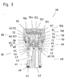
- Fig. 3 shows the structure of the elastomeric membrane breather 20 in a sectional view.
- the main body 60 of the valve core 30 - Fig. 5 - is - like the insert 40 - Fig. 4 - Is substantially hollow cylindrical shape 61 , is integrally releasably latched with the insert 45, 46, 62, has both at its lower and at its upper end depending on an external thread 1, 2 64, 66 with an intermediate, a further sealing ring 2 65 supporting Groove 75.
- This lower external thread 1 64 corresponds to the internal thread 15 of the central middle part 14 of the T-fitting 10; screwed seals the sealing ring 2 65 from the inside space between insert and center piece.
- the upper threads 66 form the releasable connection to the internal thread 153 of the lid 150 .
- the tubular 2-channel continuation of the insert 47 in the body is filled with a spiralfedergelagertem ball valve 70, 71 , wherein the valve springs 70 are supported on the one hand on the tubular projections 47 of the insert and on the other hand against two, each as a pronounced ram 92 pin of the lid insert 90 guided valve balls 71 press. These two ball valves then close the two hitherto separate channels 68 , 69 - to prevent leakage of the heating medium - when the vent attachment 80 is removed for maintenance or repair.
- an intermediate disc 130 is releasably engaged via latched on the disc latching hooks 132 ; the washer has around the center through holes for the vent 133 and in the edge zones radial slots 134 for receiving corresponding locking hooks 93 of the lid insert 90 .
- Lid, washer and lid insert are substantially cylindrical body 91 , 131 151; each half-sided axial recesses 95, 135 between the slots 134 on the underside of the washer and between the locking hooks 93 on the top of the lid insert 90 create a disc-shaped space for receiving the elasto-mergespritzten semipermeable membrane 110 as an insert 111th
- axial through holes 94 are provided as channel A, B in height of the membrane of the Dekkelencieses.
- vent cap 80 To ensure that the degassing of the heating medium takes place without exception through the holes of the lid insert and washer and semipermeable mem bran, the vent cap 80 must otherwise have a very good tightness; this is promoted by the edge 112 and transverse reinforcement 113 of the membrane or taking into account at the recesses 95, 135th
- an approximately hollow cylindrical seal 3 76 is fitted in the axial direction; this seal defined in the installed state of the lid insert with the body the way of the heating medium through the axial through holes 94 of the lid insert to the semipermeable membrane 110 and ensures the tightness of the breather 20 safely.
- the cylindrical disposition of the latching hook 132 of the intermediate disk 130 inserted into the cover bore 154 under tension takes up the hollow-cylindrical clamping device of the decorative cover 152 .
- the valve insert consisting of body and insert is tight and tight with the central center of the T-fitting screwed.
- the axially displaceable lid insert has two diametrically arranged oval projections 99, which are guided in corresponding recesses 74 of the body and ensure anti-rotation.
- the intermediate disc has arranged in the edge zones radial slots 134 for receiving corresponding latching hooks 93 of the lid insert, said compound tolerates no rotational movement, which also applies to the introduced in the space between the two components 95, 135 semipermeable membrane - grooves 97 , 136 each half Diameter take the transverse reinforcement 113 of the diaphragm positionally correct and against rotation.
- the heating medium flows through the two opposite supply / return connection pieces 11 , 12 of the T-fitting 10 in the central centerpiece 13, 14, there over the two channels A, B 42 , 43 of the insert 40 and the channels A, B 68, 69 of the base body 60 to the ball valves 70, 71, via the opened by the plunger 92 of the lid insert 90 ball valves through the holes 94 of the lid insert to the semipermeable membrane 110 for degassing via the gas channel 133, 155.
Abstract
Anschlußstück mit weiteren Funktionen für eine wassertechnische Einrichtung - insbesondere ein 3-Wege- oder T-Anschlußstück mit einem Elastomermembran-Entlüfter (1), bestehend aus einem Anschlußstück (10) mit drei, in einer Ebene liegenden, je um 90° versetzten, von einem zentralen Mittelstück (14) des Anschlußstücks ausgehenden Anschlußstutzen - nämlich einem Vorlaufstutzen (11), einem dem gegenüberliegenden Rücklaufstutzen (12) und einem mittleren Anschlußstutzen (13) - wobei das zentrale Mittelstück Mittel aufweist, die Medien Vor- und Rücklauf in dem mittleren Anschlußstutzen getrennt zu führen, dadurch gekennzeichnet, daß der Elastomermembran-Entlüfter (20) aus - einer Baugruppe Ventileinsatz (30) mit -- einem 2-kanaligen Einsatzstück (40) -- einem Kugelventil (70, 71) pro Kanal und -- einem 2-kanaligen Grundkörper (60) und - einer Baugruppe Entlüftungsaufsatz (80) mit -- einem Deckeleinsatz (90) -- einer semipermeablen Membran (110) -- einer Zwischenscheibe (130) und -- einem Schraubdeckel (150) mit Zierdeckel (152) besteht, die Baugruppen (30, 80) zu einem Entlüfter (20) gedichtet montiert sind und dieser in dem zentralen Mittelstück (14) mit den Mitteln dicht verbunden, die Medien Vor- und Rücklauf - bei geöffneten Kugelventilen, auch unter Prüfdruck - bis zur Membrane (110) getrennt führt und mittels dieser über Gaskanäle (133, 155) entgast.Connecting piece with other functions for a water technical device - in particular a 3-way or T-fitting with an elastomeric diaphragm breather (1) consisting of a connecting piece (10) with three, lying in a plane, each offset by 90 °, from a central center piece (14) of the connecting piece outgoing connecting piece - namely a flow pipe (11), the opposite return pipe (12) and a central connecting piece (13) - wherein the central center piece comprises means, the media flow and return in the central connecting piece to lead separated, characterized in that the elastomeric membrane breather (20) - An assembly valve insert (30) with - a 2-channel insert (40) - A ball valve (70, 71) per channel and a 2-channel base body (60) and - An assembly venting (80) with a lid insert (90) a semipermeable membrane (110) - An intermediate disc (130) and - a screw cap (150) with decorative lid (152) consists, the assemblies (30, 80) are mounted sealed to a breather (20) and this in the central center piece (14) with the means tightly connected, the media flow and return - with open ball valves, even under test pressure - leads to the diaphragm (110) separated and degassed by means of this via gas channels (133, 155).
Description
Die Erfindung betrifft ein Anschlußstück mit weiteren Funktionen für eine wassertechnische Einrichtung - insbesondere ein 3-Wege- oder T-Anschlußstück mit einem Elastomermembran-Entlüfter.The invention relates to a fitting with further functions for a water technical device - in particular a 3-way or T-fitting with an elastomeric membrane breather.
Anschlußeinrichtungen und Anschlußstücke werden in der Installationstechnik in wassertechnischen Anlagen wie für sanitäre Einrichtungen, Warmwasser- und Heizungsanlagen in vielfältiger Form benötigt. Rohrleitungsübergänge benötigen Kupplungs- und Verbindungsstücke, Durchmesserveränderungen von Rohrleitungen benötigen Reduzierstücke, Leitungs-Verzweigungen benötigen T-Stücke und Verbindungen von wassertechnischen Einrichtungen und Geräten mit Rohrleitungen werden mittels Anschlußstücken hergestellt. Die Anzahl der anschließenden Einrichtungen an solche Anschlußstücke ist so vielfältig wie die Anzahl leitungsmäßiger Zuund Abgänge. Im vorliegenden Fall handelt es sich beispielhaft um je einen leitungsmäßigen Zu- und Abgang sowie den Anschluß oder die Verbindung an einen/zu einem Elastomermembran-Entlüfter.Connection devices and fittings are required in the installation technology in water technical systems such as sanitary facilities, hot water and heating systems in many forms. Piping transitions require couplings and couplings, pipe diameter changes require reducers, pipe branches require tees, and piping connections and piping connections are made by fittings. The number of subsequent devices to such connectors is as varied as the number of line inputs and outputs. In the present case, it is an example of a line inlet and outlet as well as the connection or the connection to / to an elastomeric membrane breather.
Es handelt sich dabei jedoch nicht nur um eine einfache leitungsmäßige Durchgangsverbindung mit einer Geräte- oder Einrichtungs-Anschlußmöglichkeit, sondern im Bereich des Anschlusses wird noch weitere Funktionalität gefordert und dazu sind leitungsmäßige Hindernisse, Umleitungen, Schikanen oder Sperren vorgesehen. So sei an dieser Stelle beispielhaft für eine heizungstechnische Anlage vorgetragen, daß Flachheizkörper aus Platten aufgebaut sind und diese Hohlkörper parallel oder seriell mit Wasser versorgt werden können. Bei der Parallelschaltung der Heizkörperplatten werden dieselben durch Rohrleitungen so verbunden, daß das Wasser gleichzeitig in den Platten steigt und es an höchster Stelle eine Rohrverbindung zwischen den Platten mit einer Entlüftung gibt. Bei der Serienschaltung muß die Rohrverbindung zwischen den Platten so gestaltet sein, daß erst nach der Befüllung der ersten Platte - Vorlauf - das Wasser in die weitere Platte geleitet wird - Rücklauf. Diese Rohrverbindung zwischen den Platten wird üblicherweise durch ein thermisches Ventil volumengesteuert, welches den Wasserfluß bei ausreichender Raumtemperatur unterbricht. Auf der dem Ventil gegenüberliegenden Seite befindet sich ebenfalls eine Rohrverbindung zwischen den Platten mit einer Entlüftungseinrichtung, die nur im Fall des Entlüftens die Verbindung öffnet.However, this is not just a simple circuit-through connection with a device or device connection option, but in the area of the connection is still required more functionality and this are line obstacles, diversions, harassment or locks provided. Thus, for example, at this point for a heating system that flat radiators are constructed from plates and these hollow body can be supplied in parallel or in series with water. In the parallel connection of the radiator panels they are connected by pipes so that the water rises simultaneously in the plates and there is at the highest point a pipe connection between the plates with a vent. In the series connection, the pipe connection between the plates must be designed so that only after the filling of the first plate - flow - the water is passed into the other plate - return. This pipe connection between the plates is usually volume controlled by a thermal valve which interrupts the flow of water at sufficient room temperature. On the opposite side of the valve is also a pipe connection between the plates with a venting device, which opens the connection only in the case of venting.
Im folgenden wird der Stand der Technik von Anschlußstücken mit weiteren Funktionen für eine wassertechnische Einrichtung - insbesondere von 3-Wege- oder T-Anschlußstücken mit Elastomermembran-Entlüfter gewürdigt; gemäß dem Stand der Technik sind, je nach Anwendungsbezug, eine Vielzahl von Typen von Anschlußstücken mit weiteren Funktionen für eine wassertechnische Einrichtung - insbesondere ein 3-Wege- oder T-Anschlußstück mit einem Elastomermembran-Entlüfter im Einsatz.In the following, the prior art of fittings with other functions for a water technical equipment - especially of 3-way or T-fittings appreciated with elastomer membrane breather; According to the prior art, depending on the application, a variety of types of fittings with other functions for a water technical equipment - in particular a 3-way or T-fitting with an elastomeric membrane breather in use.
Mit der Patentschrift
Die Dimensionierung des Ablenkkörpers bereitet schon deshalb Probleme, daß auf den berechneten nicht einstellbaren Körper vollkommen unterschiedliche wärmebedarfsabhängige Strömungen treffen; auch der zum Abgang umgelenkte Teilstrom ist vom örtlichen lokalen Wärmebedarf abhängig. Die Fertigung des Körpers und seine lagegerechte dauerhafte Einbringung in das T-Stück sind aufwendig. Eine steuernde Ventilanordnung ist nicht vorgesehen.With the
The dimensioning of the baffle already causes problems that meet the calculated non-adjustable body completely different heat demand-dependent flows; The partial flow diverted to the outlet is also dependent on the local local heat demand. The production of the body and its position-appropriate permanent introduction into the T-piece are expensive. A controlling valve arrangement is not provided.
Die Offenlegungsschrift
Die Profiländerung wirkt sich volumenreduzierend und ggf. geräuschemittierend auf den Wasserdurchfluß aus, auf jeden Fall sind starke Verwirbelungen an der Übergangsstelle zu erwarten. Das stark reduzierte Heizplatten-Anschlußgewinde setzt beim Heizkörper ebenfalls verkürzte Überwurfmuttern für den Anschluß voraus, was eine Erhöhung der Typenvielfalt bedeutet. Das Anschlußstück läßt eine serielle Befüllung der Heizkörperplatten nicht zu; das Entlüftungsventil im Verbindungskopf kann nur beide Heizplatten gleichzeitig be-/entlüften.The publication
The change in profile has a volume-reducing and possibly noise-reducing effect on the water flow, in any case, strong turbulence is expected at the transition point. The greatly reduced hotplate connection thread requires the radiator also shortened union nuts for connection, which means an increase in the variety of types. The fitting does not allow a serial filling of the radiator plates; the venting valve in the connection head can only ventilate both heating plates at the same time.
Die deutsche Offenlegung DE 28 03 363 / Gebrauchsmuster
Die Veröffentlichungen widmen sich den Herstellungsverfahren T-förmiger Anschlußstücke; kein Hinweis auf Anlagentechnik mit Entlüftung.German disclosure DE 28 03 363 / utility model
The publications are devoted to the manufacturing process of T-shaped fittings; No indication of system technology with ventilation.
Die spanische Anmeldung
Wesenszüge der T-Anschlußstück-Konstruktion können auch ansatzweise für die Entwicklung eines derartigen Entlüftungsventils genutzt werden; in der Veröffentlichung ist die Entlüftung nicht berücksichtigt.The Spanish application
Features of the T-fitting design can also be used to some extent for the development of such a vent valve; in the publication, the ventilation is not considered.
Gebrauchsmuster
Es wird vorgeschlagen, das Anschlußelement als Kunststoff-Formteil mit wenigstens einem damit fest verbundenen Metalleinsatz auszuführen; über die Belegung der Anschlüsse werden keine Vorgaben gemacht.utility Models
It is proposed to carry out the connection element as a plastic molded part with at least one metal insert firmly connected thereto; No specifications are made about the assignment of the connections.
Die deutsche Patentschrift
Eine Entlüftungsvorrichtung sieht eine von der anderen Heizungsplatte unabhängige Entlüftung über je ein L-Stück vor; eine weitere Variante sieht ein die beiden Heizungsplatten verbindendes Rohrstück vor, welches in seiner Mitte ein Kugelventil mit L-Durchgang aufweist, so daß je nach Ventilstellung durch Drehen die Funktionen 'Geschlossen', 'Platte 1 geöffnet' oder 'Platte 2 geöffnet' eingestellt werden können.
Bei der dritten Varianten ist in der Mitte des plattenverbindenden Rohrstücks eine Doppelsitzausbildung mit einer radial gerichteten Entlüftungsschraube vorgesehen; diese Funktion bleibt unklar, die angekündigte separate Entlüftung der Platten ist nicht gegeben.A venting device provides independent ventilation from the other heater plate via one L-piece each; another variant provides a connecting the two heating plates pipe section, which has a ball valve with L-passage in its center, so that depending on the valve position by turning the functions 'Closed', '
In the third variants, a double seat formation with a radially directed vent screw is provided in the middle of the plate-connecting pipe section; this function remains unclear, the announced separate ventilation of the plates is not given.
Die deutsche Gebrauchsmusterschrift
Das Mittelstück gestattet die Aufnahme verschiedener Einrichtungen, wie einen Blindstopfen, einen Ventileinsatz oder einen Entlüftungseinsatz, ist jedoch nicht für eine Dauerentlüftung mit Elastomermembran-Entlüfter ausgelegt.The German Utility Model
The center piece accommodates various devices, such as a blind plug, valve insert or vent insert, but is not designed for continuous venting with elastomeric membrane breather.
Gebrauchsmuster
Das Ventileinsatzelement besteht aus einem Ventilkörper und einem rohrförmigen Anschlußabschnitt, der mittels eines umlaufenden Dichtungselements dichtend an einen Verbindungsabschnitt des Anschlußteils steuerbar anschließt. Um ein universelles, unabhängig von der Art des Anschlußteils einsetzbares Ventileinsatzelement zu erhalten, besitzt der Anschlußabschnitt zwei umlaufende Dichtungselemente, wobei das erste Dichtungselement an einer unteren Stirnseite des Anschlußabschnitts und das zweite Dichtungselement an einer Mantelfläche des Anschlußabschnitts angeordnet ist.
Gemäß der deutschen Offenlegung
Anschlußteil und Ventileinsatzelement bilden ein Systembaukasten; das Ventileinsatzelement kann sowohl für Anschlußteile mit stirnseitiger Flachzylinderabdichtung als auch für Anschlußteile mit innerem durchströmten Rohrabschnitt zum Einsatz kommen, wobei die Dichtung an der inneren oder äußeren Mantelfläche des Rohrabschnitts erfolgt. Die Abmessungen des universellen Ventileinsatzelements müssen zunächst an der Flachzylinderabdichtung bemessen werden.utility Models
The valve insert element consists of a valve body and a tubular connecting portion which connects by means of a circumferential sealing element sealingly connected to a connecting portion of the connecting part. In order to obtain a universal, usable regardless of the type of connector valve insert element, the connecting portion has two circumferential sealing elements, wherein the first sealing element is arranged on a lower end side of the connecting portion and the second sealing element on a lateral surface of the connecting portion.
According to the
Connecting part and valve insert form a modular system; the valve insert element can be used both for connecting parts with face-side flat cylindrical seal as well as for connecting parts with inner through-flowed pipe section, wherein the seal is made on the inner or outer circumferential surface of the pipe section. The dimensions of the universal valve insert element must first be dimensioned on the flat cylinder seal.
Das deutsche Gebrauchsmuster
Die Teilevielfalt verbunden mit einer zwingend notwendigen, einzuhaltenden Maßhaltigkeit geringer Toleranzbreite zwingt zu einer Verschlankung des Produkts - nicht zuletzt wegen einzuhaltender Stückkosten für ein konsumerorientiertes Produkt.The German
The variety of parts associated with a mandatory, to be complied with dimensional tolerance narrow tolerance width forces to a slimming of the product - not least because of persevering unit costs for a consumer-oriented product.
Be- und Entlüftungsautomaten mit Elastomermembran sind gemäß des Stands der Technik bekannt und bestehen üblicherweise aus einer Deckelkappe, einem Oberteil, einer Membran sowie einem Unterteil. Die Kunststoffteile Deckelkappe und Oberteil sind zweiteilig gespritzt, werden aber durch Fügen und Schweißen, Pressen und/oder Kleben einstückig. Ober- und Unterteil werden miteinander über die zwischengefügte Membran als Einlegeteil mit/ohne Träger oder besser mit im Oberteil im 2K oder Mehr-K (Komponenten)-Verfahren angespritzte Membran als Dichtteil verschraubt. Das vorzugsweise Kunststoff-Unterteil besitzt darüber hinaus ein Kugelventil, welches mittels einer Kugel und einer Schraubenfeder gegen eine Zentralbohrung im Unterteil dichtet, beeinflußt jedoch durch einen Stößel des Oberteils, der je nach Schraubtiefe zwischen Ober- und Unterteil einen Gas- und Flüssigkeitskanal freigibt. Das Unterteil besitzt - ähnlich einer Doppelmuffe - ein weiteres Außengewinde, welches, mit einem Dichtring versehen, die Verbindung zur Heizungs- oder Warmwasseranlage oder sonstigen geschlossenen Rohrkreisläufen bildet.Automatic vents with elastomeric membrane are known in the prior art and usually consist of a cover cap, an upper part, a membrane and a lower part. The plastic parts cover cap and upper part are sprayed in two parts, but are integrally by joining and welding, pressing and / or gluing. Upper and lower parts are bolted together as an insert with / without support or better with molded in the upper part in the 2K or multi-K (component) method membrane as a sealing part. The preferably plastic lower part also has a ball valve, which seals by means of a ball and a coil spring against a central bore in the lower part, but influenced by a plunger of the upper part, depending on the screw depth between the upper and lower part releases a gas and liquid channel. The lower part has - similar to a double socket - another external thread, which, provided with a sealing ring, the connection to the heating or hot water system or other closed pipe circuits forms.
Die deutsche Anmeldung 'Be- und Entlüftungsautomat mit Membran als Systembaukasten',
Gemäß der deutschen Patentanmeldung
Der Vorteil des Be- und Entlüftungsautomaten 2 gegenüber dem der vorangegangenen Anmeldung ist, daß die aufwendige Anfertigung und Prüfung der aus Membranfolie und Träger bestehenden semipermeablen Membranpatrone entfällt.According to the German
The advantage of the automatic vending machine 2 over that of the previous application is that the elaborate preparation and testing of the membrane film and carrier existing semipermeable membrane cartridge is eliminated.
Der Be- und Entlüftungsautomat mit Elastomermembran 3 - deutsche Patentanmeldung
Vorgestellt wird ein weiterer Be- und Entlüftungsautomat mit Elastomermembran 4, gemäß Patentanmeldung
Der Adapter besitzt eine nach oben weisende Bohrung für die Membran-Dauerentlüftung. In einem zylinderförmigen Hohlraum zwischen Adapter und Doppelnippel befindet sich die einstückig mit dem Adapter verbundene, U-scheibenförmig ausgebildete semipermeable Membrandichtung. Sie führt mit der Links-/Rechts-Verschrau-bung von Deckel und Adapter eine Auf-/Ab-Bewegung aus und bildet somit ein Offen-/Zu-Ventil für die Schnellentlüftung und ggf. über den Ventilstößel für das Kugelventil. Ein weiterer Vorteil des Be- und Entlüftungsautomaten 4 gegenüber den vorangegangenen Veröffentlichungen ist neben der einstückigen Membranausführung mit Träger die Separierbarkeit und Eigenständigkeit des aufgebrachten Deckels; der Deckel überdeckt vollständig den Elastomermembran-Entlüfter und seine Ausführungsform und Gestaltung bestimmen das Erscheinungsbild des Automaten in Formund Farbgebung.Presented is another automatic ventilation with elastomeric membrane 4, according to the
The adapter has an upwardly facing hole for the membrane continuous venting. In a cylindrical cavity between adapter and double nipple is the integrally connected to the adapter, U-shaped disk-shaped semipermeable membrane seal. It performs an up / down movement with the left / right screw connection of cover and adapter and thus forms an open / close valve for the quick exhaust and, if necessary, via the valve tappet for the ball valve. Another advantage of the automatic vending machine 4 compared to the previous publications, in addition to the one-piece membrane design with carrier separability and independence of the applied lid; the lid completely covers the elastomeric membrane breather and its embodiment and design determine the appearance of the machine in shape and color.
Bei der Entlüftung wird ganz auf bekannte halbautomatische oder automatische Entlüfter mit Schwimmertechnologie verzichtet und die ohne mechanisch bewegliche Teile auskommende Membran-Technologie bevorzugt eingesetzt. Mit dem Verzicht auf die Schwimmertechnologie geht auch der Verzicht auf eine automatische Anlagen-Schnellentlüftung einher, die jedoch abschließender Bestandteil bei allen Installations-, Instandsetzungs- und Reparatur- und Wartungsarbeiten an wasserführenden Anlagen ist.When venting is completely dispensed with known semi-automatic or automatic deaerator with float technology and preferably used without mechanical moving parts membrane technology. The waiver of the float technology is also the waiver of an automatic system quick exhaust, but this is a final component in all installation, repair and repair and maintenance of water-bearing systems.
Alle vorgestellten Veröffentlichungen eignen sich nur bedingt oder gar nicht für den spezifischen Einsatz als Anschlußstück mit weiteren Funktionen für eine wassertechnische Einrichtung - insbesondere nicht als 3-Wege- oder T-Anschlußstück mit einem Elastomermembran-Entlüfter.All publications presented are only partially or not at all for the specific use as a fitting with other functions for a water technical equipment - especially not as a 3-way or T-fitting with an elastomeric membrane breather.
Der Erfindung liegt daher die Aufgabe zu Grunde, eine Einrichtung nach dem Oberbegriff des Anspruchs 1, ein Anschlußstück mit weiteren Funktionen für eine wassertechnische Einrichtung - insbesondere ein 3-Wege- oder T-Anschlußstück mit einem Elastomermembran-Entlüfter zu schaffen.The invention is therefore based on the object, a device according to the preamble of
Diese Aufgabe wird erfindungsgemäß durch die kennzeichnenden Merkmale des Anspruchs 1 gelöst; auf vorteilhafte Ausgestaltungen nehmen die Unteransprüche Bezug.This object is achieved by the characterizing features of
Ein 3-Wege- oder T-Anschlußstück ist bekannt und wird u.a. zum Anschließen von Heizkörpern an Warmwasserkreisläufe oder mechanische und strömungstechnische Verbindung zwischen mindestens zwei Heizkörperplatten, wobei ein dritter Anschluß zur freien Verfügung steht, wie zum Anschluß eines thermischen Ventils, eines dichtenden Verschlußstopfens oder eines verschließbaren Entlüftungseinsatzes, zwecks Aufbau eines Ventils oder eines Verteilers. Das Anschlußstück besteht aus einem Mittelstück und drei, meist in der Ebene je im rechten Winkel versetzten Anschlußstutzen, wobei im Mittelstück entsprechende Kanäle vorgesehen sind, die durch Übergänge und Dichtflächen geschaffen sind, und gewünschte offene oder einstellbare Strömungsverbindungen bilden. Üblicherweise weist das Anschlußstück für jeden Anschlußstutzen im Mittelstück einen eigenen Kanal auf, so daß durch unterschiedliche Einsätze am mittleren Anschlußstutzen Einfluß auf die Strömungsverhältnisse zwischen den Kanälen der beiden außenliegenden Anschlußstutzen genommen werden kann.A 3-way or T-fitting is known and is used, inter alia, for connecting radiators to hot water circuits or mechanical and fluidic connection between at least two radiator plates, with a third port is at leisure, such as for connecting a thermal valve, a sealing stopper or a lockable vent insert for the purpose of constructing a valve or manifold. The fitting consists of a central piece and three, usually in the plane offset at right angles connecting piece, wherein the middle piece corresponding channels are provided, which are provided by transitions and sealing surfaces, and form desired open or adjustable flow connections. Usually, the connector for each connection piece in the middle piece has its own channel, so that influence by different applications on the central connection piece influence on the flow conditions between the channels of the two outer connecting piece can be taken.
Eine weitere Ausgestaltung der Erfindung sieht vor, daß das Anschlußstück in seinem Mittelstück einen als Dichtfläche ausgeprägten, flachzylinderförmigen Übergang aufweist und an dem der Ventilstößel eines Ventileinsatzes oder die BlindstopfenStirnseite eines Blindanschlusses dichtend anliegt. In einer weiteren Ausprägungsform ist der Blindstopfen als Entlüftungseinsatz ausgebildet, an dem ein Entlüftungsventil anschließbar ist, durch welches der Heizkörper zu entlüften ist. Umgekehrt kann der Flachzylinder-Übergang auch als Dichtelement ausgeprägt sein, je nach Werkstoffkomponenten auf der einen oder der anderen Seite der Dichtung. Eine weitere Ausführung sieht eine Dichtfläche als hohlzylinderförmigen Ansatz vor, wobei die Dichtung mittels eines Einsatzes über dessen ebenfalls als Hohlzylinder ausgeführten Außen- oder Innenwand korrespondierend erfolgt. Während bei der flachzylinderförmigen Dichtung es nur eine 'Auf'- oder 'Zu'-Stellung gibt, läßt die Hohlzylinder-Lösung je nach Höhe des Zylinders einen Verfahrweg und damit eine wegabhängige Dichtung oder Öffnung auch mit Mehrweg-Ventilcharakter zu.A further embodiment of the invention provides that the connecting piece has in its middle part a pronounced as a sealing surface, flat cylindrical transition and against which the valve stem of a valve insert or the dummy plug face of a blind terminal sealingly. In a further embodiment, the blind plug is designed as a vent insert to which a vent valve can be connected, through which the radiator is to vent. Conversely, the flat cylinder transition can also be pronounced as a sealing element, depending on the material components on one or the other side of the seal. A further embodiment provides a sealing surface as a hollow cylindrical projection, wherein the seal is effected by means of an insert via its likewise designed as a hollow cylinder outer or inner wall corresponding. While in the flat cylindrical seal there is only a 'up' or 'to' position, the hollow cylinder solution allows depending on the height of the cylinder a travel and thus a path-dependent seal or opening with reusable valve character.
Der Baukasten 'Anschlußstück mit Elastomer-Membranentlüfter 2' setzt auf einem bekannten 3-Wege- oder T-Anschlußstück mit einem Vorlauf- - Kanal A - und einem um 180°-versetzten Rücklauf-Anschlußstutzen - Kanal B - sowie einem weiteren, in der von den beiden obigen Stutzen aufgespannten Ebene und von diesen um je 90° versetzt gelagerten mittleren Anschlußstutzen mit einem zentralen Mittelstück mit getrennter Kanalführung auf, von dem aus die Stutzen ausgehen. Das 3-Wege- oder T-Anschlußstück ist Handelsware; das zentrale Mittelstück besitzt eine flach- oder eine innen- oder außenanschließbare hohlzylinderförmige Dichtfläche für den mittleren Funktionsanschluß.The kit 'fitting with elastomer diaphragm vent 2' is based on a known 3-way or T-connector with a flow - channel A - and a 180 ° offset return connection piece - channel B - and another, in the Spaced by the two above-mentioned nozzle level and offset from these by 90 ° each mounted central connecting piece with a central center piece with separate channel guide, from which go out the nozzle. The 3-way or T-fitting is a commodity; the central center piece has a flat or an inside or Außenanschließbare hollow cylindrical sealing surface for the middle function terminal.
Der Baukasten 'Anschlußstück mit Elastomer-Membranentlüfter 2' besteht - vom Anschlußstück aus gesehen - aus einer Baugruppe Ventileinsatz und einer Baugruppe Entlüftungsaufsatz, die folgende, im wesentlichen zylinderförmige Bauteile beinhalten
- Baugruppe Ventileinsatz
- -- 2-kanaliges Einsatzstück
- -- Kugelventil pro Kanal
- -- 2-kanaliger Grundkörper sowie
- -- Satz diverser Federn und Dichtungen
- Baugruppe Entlüftungsaufsatz
- -- Deckeleinsatz
- -- Semipermeable Membran
- -- Zwischenscheibe
- -- Deckel mit Zierdeckel sowie
- -- Satz diverser Federn und Dichtungen.
- Assembly valve insert
- - 2-channel insert
- - Ball valve per channel
- - 2-channel body as well
- - Set of various springs and seals
- Assembly venting attachment
- - Lid insert
- - Semipermeable membrane
- - washer
- - Lid with decorative lid as well
- - Set of various springs and seals.
Das Anschlußstück ist - wie oben dargestellt - Teil einer Handelsware und ist in der Ausführung mit Mittelstück-Stirndichtung und in der Ausführung mit Mittelstück-Hohlzylinderdichtung am Markt erhältlich. Die Bauteile sind im wesentlichen - bis auf die Federelemente - aus Kunststoff gefertigt; die Dichtungen sind Elastomer-Teile. Die Kunststoff-Teile können auch als Dreh- oder Frästeile aus Metall - wie Messing oder Rotguß - hergestellt sein. Die Bauteile sind zu einer einsatzfähigen Baugruppe einstückig gefügt. Der Elastomermembran-Entlüfter - bestehend aus den Baugruppen Ventileinsatz und Entlüftungsaufsatz - wird in das zentrale Mittelstück des T-Anschlußstücks dicht verschraubt.The fitting is - as shown above - part of a commodity and is available in the version with central end seal and in the version with central hollow cylinder seal on the market. The components are essentially made of plastic except for the spring elements; the seals are elastomer parts. The plastic parts can also be made as turned or milled parts made of metal - such as brass or gunmetal. The components are joined in one piece to form an operational module. The elastomer diaphragm breather - consisting of the valve insert and venting unit assemblies - is tightly screwed into the central center piece of the T-fitting.
Eine weitere Ausprägung der Erfindung sieht vor, daß das 2-kanalige Kanal A-/Kanal B-Einsatzstück des Ventileinsatzes an seinem unteren Ende einen dichtenden Anschluß für einen Kanal des zentralen Mittelstücks des Anschlußstücks besitzt; der zu dichtende Anschluß des Mittelstücks ist mechanisch entweder
- als Flachzylinder ausgeführt und die stirnseitige Flachdichtung des Einsatzstücks dichtet gegen den Flachzylinder oder
- als hohlzylinderförmiger Stutzen ausgeführt und das Gegenstück des Einsatzstücks ist ebenfalls mit einem Rohransatz versehen und dichtet innen, außen oder stirnseitig am Stutzen.
- designed as a flat cylinder and the end-face gasket of the insert seals against the flat cylinder or
- designed as a hollow cylindrical neck and the counterpart of the insert is also provided with a pipe socket and seals inside, outside or front side of the nozzle.
Im zweiten Fall können auch mehrere Dichtringe als Normteile zum Einsatz kommen oder auch eine Dichtmanschette als Konstruktionsteil, die sowohl innen, stirnseitig und außen dichten kann. Da an dieser Stelle keine weiteren Anforderungen - wie z.B. eine Ventilfunktion, o.ä. - gestellt sind, ist die Flachzylinder-Variante die wirtschaftlichste Lösung. Jedoch ist es sinnvoll, den Anschluß universell auszuführen, da beide T-Stückvarianten am Markt geführt werden und eine Verwechselung ausgeschlossen werden kann.In the second case, several sealing rings can be used as standard parts or a sealing sleeve as a structural part, which can seal both inside, front and outside. Since there are no other requirements at this point - e.g. a valve function, or similar - are set, the flat cylinder variant is the most economical solution. However, it makes sense to universally execute the connection, since both T-piece variants are performed on the market and a confusion can be excluded.
Gemäß einer weiteren Ausgestaltung der Erfindung führt der zweite Zulauf des T-Anschlußstücks führt - von dem ersten getrennt - über einen seitlichen Einlaß in den zweiten Kanal des Einsatzstücks; gedichtet wird dieser Raum erst mittels eines Dichtrings des Grundkörpers durch eine Schraubverbindung zwischen dem zentralen Mittelstück des T-Anschlußstücks mit dem Elastomermembran-Entlüfter. Das 2-kanalige Einsatzstück ist mit dem Grundkörper des Elastomermem-bran-Entlüfters über eine mechanische trennbare Schnittstelle einstückig dicht verbunden; über zwei seitliche Quernuten des Einsatzstücks rasten zwei Federn des Grundkörpers in den Nuten des Einsatzstücks. Die beiden symmetrisch angeordneten, hohlzylinderförmigen Kanäle des Einsatzstücks weisen am oberen Ende je einen rohrförmigen Überstand auf, die je mit zwei Dichtringen belegt ihre hohlzylinderförmige, weiterhin getrennte Fortsetzung in dem Grundkörper finden.According to a further embodiment of the invention, the second inlet of the T-fitting leads - separated from the first - via a lateral inlet in the second channel of the insert; This space is sealed only by means of a sealing ring of the body by a screw connection between the central center piece of the T-fitting with the elastomeric membrane breather. The 2-channel insert is integrally tightly connected to the main body of the elastomer membrane deaerator via a mechanical separable interface; Two springs of the main body snap into the grooves of the insert over two lateral transverse grooves of the insert. The two symmetrically arranged, hollow cylindrical channels of the insert have at the top of each a tubular projection, each occupied by two sealing rings find their hollow cylindrical, still separate continuation in the body.
Eine weitere vorteilhafte Ausgestaltung der Erfindung sieht vor, daß der Grundkörper des Ventileinsatzes - wie das Einsatzstück - im wesentlichen hohlzylinderförmiger Gestalt ist, mit dem Einsatzstück einstückig trennbar verrastet ist und sowohl an seinem unteren als auch an seinem oberen Ende je ein Außengewinde mit einer dazwischenliegenden, einen weiteren Dichtring tragenden Nut hat. Dieses untere Außengewinde korrespondiert mit dem Innengewinde des zentralen Mittelstücks des T-Anschlußstücks; eingeschraubt dichtet der Dichtring den Raum zwischen Einsatzstück und Mittelstück ab. Die oberen Gewindegänge bilden die lösbare Verbindung zu dem Innengewinde des Deckels. Die rohrförmige 2-kanalige Fortsetzung des Einsatzstücks in den Grundkörper ist ausgefüllt mit je einem spiralfedergelagertem Kugelventil, wobei die Ventilfedern sich einerseits auf den rohrförmigen Überständen des Einsatzstücks abstützen und andererseits gegen zwei, über je einen als Stößel ausgeprägten Stift des Deckeleinsatzes geführte Kugeln drücken. Diese beiden Kugelventile schließen die beiden bisher getrennt geführten Kanäle dann ab - um ein Auslaufen des Heizungsmediums zu verhindern - wenn der Entlüftungsaufsatz zu Wartungszwecken oder Reparaturarbeiten entfernt ist.A further advantageous embodiment of the invention provides that the base body of the valve core - as the insert - is substantially hollow cylindrical shape, is integrally releasably latched with the insert and each at its lower and at its upper end an external thread with an intermediate, another groove bearing groove has. This lower external thread corresponds to the internal thread of the central center of the T-fitting; screwed seals the sealing ring from the space between insert and center piece. The upper threads form the releasable connection to the internal thread of the lid. The tubular 2-channel continuation of the insert in the body is filled with a spiralfedergelagertem ball valve, the valve springs are supported on the one hand on the tubular projections of the insert and on the other hand pressed against two, each pronounced as a ram pin of the lid insert guided balls. These two ball valves then close the two hitherto separate channels - to prevent leakage of the heating medium - when the vent attachment is removed for maintenance or repair.
Eine weitere Ausprägungsform der erfinderischen Neuheit ist dadurch gegeben, daß Deckel, Zwischenscheibe, semipermeable Membran, Deckeleinsatz, Dichtung und Zierdeckel den zylinderförmigen Entlüftungsaufsatz nach Art des oben beschriebenen Be- und Entlüftungsautomaten mit semipermeabler Elastomermembran bilden. In eine Zentralbohrung des Deckels wird eine Zwischenscheibe über an der Scheibe angespritzte Rasthaken lösbar eingerastet; die Zwischenscheibe weist um das Zentrum Durchgangsbohrungen für die Entlüftung und in den Randzonen radiale Langlöcher zur Aufnahme von korrespondierenden Rasthaken des Deckeleinsatzes auf. Deckel, Zwischenscheibe und Deckeleinsatz sind im wesentlichen zylinderförmige Körper; je halbseitige axiale Aussparungen zwischen den Langlöchern auf der Unterseite der Zwischenscheibe und zwischen den Rasthaken auf der Oberseite des Deckeleinsatzes schaffen einen scheibenförmigen Zwischenraum zwecks Aufnahme der elastomergespritzten semipermeablen Membran als Einlegeteil. Ein im Mehr-K-Spritzverfahren hergestellte Kombination aus Zwischenscheibe und Membran oder Deckeleinsatz und Membran oder einen alle drei Bauteile einschließende Membraneinsatz ist ebenfalls zu prüfen. Für die Funktionsfähigkeit einer automatisierten Entlüftung sind in Höhe der Membran des Deckeleinsatzes ebenfalls axiale Durchgangsbohrungen vorgesehen. Einerseits muß die Kombination aus Deckeleinsatz, Membran und Zwischenscheibe dem Anlagenprüfdruck über die Prüfzeit standhalten und andererseits ist die Kombination so zu bemessen, daß ausreichend Permeation zwischen der Anlage und dem Umfeld stattfindet. Zu diesem Zweck ist unbedingt sicherzustellen, daß die Entgasung der Anlage ausnahmslos über die Bohrungen von Deckeleinsatz und Zwischenscheibe und semipermeabler Membran stattfindet und der Entlüftungsaufsatz ansonsten eine sehr gute Dichtigkeit aufweist.A further embodiment of the inventive novelty is given by the fact that lid, washer, semipermeable membrane, lid insert, seal and decorative lid form the cylindrical vent attachment on the type of the above-described automatic ventilation with semipermeable elastomeric membrane. In a central bore of the lid, an intermediate disc is releasably engaged via molded onto the disc latch hooks; the intermediate disc has through the center through holes for the vent and in the edge zones radial slots for receiving corresponding latching hooks of the lid insert. Lid, washer and lid insert are substantially cylindrical body; each half-sided axial recesses between the oblong holes on the underside of the washer and between the latching hooks on the top of the lid insert create a disc-shaped space for receiving the elastomergespritzten semipermeable membrane as an insert. A combination of washer and diaphragm or lid insert and diaphragm made in a multi-K spray process or a diaphragm insert including all three components shall also be tested. For the functionality of an automated venting axial through holes are also provided at the level of the membrane of the lid insert. On the one hand, the combination of lid insert, membrane and washer must withstand the system test pressure over the test time and on the other hand, the combination must be such that sufficient permeation takes place between the system and the environment. For this purpose, it is essential to ensure that the degassing of the system without exception takes place via the holes in the lid insert and washer and semi-permeable membrane, and that the ventilation attachment otherwise has a very good seal.
Eine weitere Ausgestaltung der Erfindung sieht vor, daß zur Komplettierung des Entlüftungsaufsatzes der Deckelaufsatz unterseitig in axialer Richtung eine etwa hohlzylinderförmige Dichtung übergestülpt bekommt; diese Dichtung definiert im verbauten Zustand des Deckeleinsatzes mit dem Grundkörper den Weg des Heizungsmediums über die axialen Durchgangsbohrungen des Deckeleinsatzes bis zur semipermeablen Membran und stellt die Dichtigkeit des Aufsatzes sicher. Außerdem nimmt die zylinderförmige Auflassung der in die Deckelbohrung gesteckten Rasthaken der Zwischenscheibe unter Spannung die hohlzylinderförmig ausgeprägte Klemmeinrichtung des Zierdeckels auf und sichert so die Zwischenscheibe gegen Entnahme oder Ausfall. Der Zierdeckel trägt zur Wertanmutung des Entlüftungsaufsatzes bei, deckt die Technik des Deckels ab und seine sichtbare Oberfläche eignet sich zur Anbringung werbetechnischer Aussagen, wie Eigennamen, Herstellerbezeichnung, Typangaben, Artikelnummern, o.ä.A further embodiment of the invention provides that to complete the vent attachment of the lid attachment gets slipped over the underside in the axial direction an approximately hollow cylindrical seal; this seal defines in the installed state of the lid insert with the body the way of the heating medium on the axial through holes of the lid insert to the semipermeable membrane and ensures the tightness of the essay safe. In addition, the cylindrical release of the inserted into the cover hole locking hooks of the intermediate disc under tension on the hollow cylindrical clamping device of the decorative cover and thus secures the washer against removal or failure. The decorative cover adds to the appearance of the vent attachment, covers the Technique of the lid off and its visible surface is suitable for attaching promotional statements, such as proper name, manufacturer's name, type, article numbers, or similar.
Nach Montage des Ventileinsatzes - des Grundkörpers mit dem gerasteten Einsatz und den Kugelventilen - in dem zentralen Mittelstück des T-Anschlußstücks durch Verschrauben und Dichten, wozu der Grundkörper an seiner Oberseite über einen Vierkant-Schlüsselansatz zum Nachziehen verfügt, wird der vollständige Entlüftungaufsatz über das Innengewinde an der Unterseite des Deckels mit dem dann aus dem zentralen Mittelstück herausragenden Teil des Grundkörpers mit seinem korrespondierenden Außengewinde verschraubt, wobei aus der Dreh- eine Längsbewegung erzeugt wird, wobei mit dem Deckel auch die Zwischenscheibe, die Membrane und der Deckeleinsatz verfahren werden und die bis dahin die Kanäle dichtenden Kugeln der beiden Kugelventile im Innenraum zwischen Grundkörper und Einsatz durch die auf die Kugeln drückenden als Stößel ausgebildete Stifte des Deckeleinsatzes die Kugelventile öffnen - oder durch Lösen des Deckels schließen.After mounting the valve core - the main body with the notched insert and the ball valves - in the central center of the T-fitting by screwing and sealing, including the main body has a square key approach to retighten at its top, the complete venting essay on the internal thread screwed to the underside of the lid with the then protruding from the central part of the main body with its corresponding external thread, wherein from the rotary is generated a longitudinal movement, wherein with the cover and the intermediate disc, the membrane and the lid insert are moved and the bis to the channels sealing balls of the two ball valves in the interior space between the base body and insert through the pressing on the balls designed as a ram pins of the lid insert the ball valves open - or close by loosening the lid.
Gemäß einer weiteren bevorzugten Ausprägung der Erfindung bleiben außer dem durch ein Loslager drehbar gelagerten Deckel die Bauteile des Ventileinsatzes Einsatz und Grundkörper sowie des Entlüftungsaufsatzes Deckeleinsatz, Membrane und Zwischenscheibe lagegerecht zueinander. Der Ventileinsatz bestehend aus Grundkörper und Einsatz ist fest sitzend und dicht mit dem zentralen Mittelstück des T-Anschlußstücks verschraubt. Der axial verschiebliche Deckeleinsatz besitzt zwei diametral angeordnete ovale Auskragungen, die in korrespondierenden Ausnehmungen des Grundkörpers geführt werden und eine Verdrehsicherheit gewährleisten. Die Zwischenscheibe weist in den Randzonen angeordnete radiale Langlöcher zur Aufnahme von korrespondierenden Rasthaken des Deckeleinsatzes auf, wobei diese Verbindung keine Drehbewegung toleriert, was auch auf die im Zwischenraum der beiden Bauteile eingebrachte semipermeable Membrane zutrifft.According to a further preferred embodiment of the invention except for the rotatably mounted by a floating bearing lid components of the valve core insert and body and the vent cap lid insert, diaphragm and washer are in line with each other. The valve insert consisting of body and insert is firmly seated and tightly bolted to the central center piece of the T-fitting. The axially displaceable lid insert has two diametrically arranged oval projections, which are guided in corresponding recesses of the body and ensure anti-rotation. The intermediate disc has arranged in the edge zones radial slots for receiving corresponding locking hooks of the lid insert, said compound tolerates no rotational movement, which also applies to the introduced in the space between the two components semipermeable membrane.
Ist in einer weiteren bevorzugten Ausführung der erfinderischen Neuheit zwischen den beiden Platten eines Plattenheizkörpers ein T-Anschlußstück mit Elastomermembran-Entlüfter installiert, strömt das Heizungsmedium durch die beiden gegenüberliegenden Anschlußstutzen des T-Anschlußstücks in das zentrale Mittelstück, dort geleitet über die beiden Kanäle des Einsatzes in den Raum zwischen Einsatz und Grundkörper und zu den Kugelventilen, über die geöffneten Kugelventile durch die Bohrungen des Deckeleinsatzes zu der semipermeablen Membran zum Entgasen.Is installed in a further preferred embodiment of the inventive novelty between the two plates of a panel radiator a tee with elastomeric membrane breather, the heating medium flows through the two opposite connection piece of the T-fitting in the central centerpiece, where conducted over the two channels of the insert in the space between insert and body and to the ball valves, through the open ball valves through the holes in the lid insert to the semipermeable membrane for degassing.
Eine vorteilhafte Variation in der Steuerung der Kugelventile von z.Zt. beide Ventile 'Auf' oder 'Zu' in das ein oder andere Ventil 'Auf oder 'Zu' ergibt sich dadurch, daß der Deckeleinsatz mit einem weiteren als Stößel ausgeprägten Stift versehen wird, der in einer um 45° axial gedrehten Stellung des Deckeleinsatzes wirksam wird und auf die eine oder andere Kugel bei Verschrauben des Deckels wirkt. Mit einer Bedienung von außen wird die Festeinstellung umgangen und kann zu Prüfzwecken oder Wartungsarbeiten von Bedeutung sein. In diesem Fall muß dem Grundkörper an geeigneter Stelle eine oder zwei weitere 45°-versetzte Ausnehmungen hinzugefügt werden, wenn beide Kugelventile auch getrennt angesprochen werden sollen, so daß vier Betriebszustände möglich sind, wie
- a) Vor- und Rücklauf geschlossen
- b) Vorlauf geöffnet, Rücklauf geschlossen
- c) Vorlauf geschlossen, Rücklauf geöffnet
- d) Vor- und Rücklauf geöffnet.
- a) flow and return are closed
- b) Flow open, return closed
- c) flow closed, return flow open
- d) supply and return open.
Unter Pkt. b) wird der Vorlauf der wassertechnischen Anlage über Kanal A entlüftet, unter Pkt. c) wird der Rücklauf der Anlage über Kanal B entlüftet und unter Pkt. d) werden Vor- und Rücklauf der Anlage über Kanal A und Kanal B entlüftet. Die Pkte. b) - c) sind für die Entlüftung von seriell geschalteten Platten von Flachheizkörpern von Bedeutung, Pkt. d) ist für die Entlüftung von parallel arbeitenden Platten von Flachheizkörpern von Belang.Under point b), the supply of the water-technical system is vented via duct A, under point c) the return of the system is vented via duct B and under point d) the flow and return of the system via duct A and duct B are vented , Points b) - c) are important for the venting of plates of flat radiators connected in series, point d) is of importance for the ventilation of parallel plates of flat radiators.
Der Gegenstand der Erfindung wird nachfolgend anhand der als Anlage beigefügten Zeichnungen von Ausführungsbeispielen weiter verdeutlicht. Es zeigen
- Fig. 1
- Elastomermembran-Entlüfter, in Perspektive
- a) Unteransicht
- b) Draufsicht
- Fig. 2
- Anschlußstück mit Elastomermembran-Entlüfter, Explosionsdarstellung
- Fig. 3
- Elastomermembran-Entlüfter, Schnittdarstellung
- Fig. 1
- Elastomer membrane breather, in perspective
- a) bottom view
- b) top view
- Fig. 2
- Connecting piece with elastomer diaphragm breather, exploded view
- Fig. 3
- Elastomer membrane deaerator, sectional view
Die folgenden Figuren zeigen in Perspektive und je in a) Unteransicht und b) Draufsicht
- Fig. 4
- Einsatzstück
- Fig. 5
- Grundkörper
- Fig. 6
- Deckeleinsatz
- Fig. 7
- Semipermeable Membran
- Fig. 8
- Zwischenscheibe
- Fig. 9
- Schraubdeckel.
- Fig. 4
- insert
- Fig. 5
- body
- Fig. 6
- lid insert
- Fig. 7
- Semipermeable membrane
- Fig. 8
- washer
- Fig. 9
- Screw cap.
Gleiche und gleichwirkende Bestandteile der Ausführungsbeispiele sind in den Figuren jeweils mit denselben Bezugszeichen versehen.The same and equivalent components of the embodiments are each provided with the same reference numerals in the figures.
Die Beschreibung der erfindungsgemäßen Einrichtung wird fortgesetzt anhand der Erläuterung der Figuren.The description of the device according to the invention will be continued with reference to the explanation of the figures.
Wie aus
- Baugruppe Ventileinsatz
- -- 2-
kanaliges Einsatzstück 40 - -- Kugelventil pro Kanal
- -- 2-
kanaliger Grundkörper 60 - -- Satz diverser Federn und Dichtungen
- -- 2-
- Baugruppe Entlüftungsaufsatz
- --
Deckeleinsatz 90 - --
Semipermeable Membran 110 - --
Zwischenscheibe 130 - --
Deckel 150 mit Zierdeckel sowie - -- Satz diverser Federn und Dichtungen.
- --
- Assembly valve insert
- - 2-
channel insert 40 - - Ball valve per channel
- 2-
channel base body 60 - - Set of various springs and seals
- - 2-
- Assembly venting attachment
- -
Lid insert 90 -
Semipermeable membrane 110 - -
Washer 130 - -
Lid 150 with decorative lid as well - - Set of various springs and seals.
- -
Gemäß
Das Anschlußstück 10 ist - wie oben dargestellt - Teil einer Handelsware und ist in der Ausführung mit Mittelstück-Stirndichtung und in der Ausführung mit Mittelstück-Hohlzylinderdichtung am Markt erhältlich. Die Bauteile sind im wesentlichen - bis auf die Federelemente - aus Kunststoff gefertigt; die Dichtungen sind Elastomer-Teile. Die Kunststoff-Teile können auch als Dreh- oder Frästeile aus Metall - wie Messing oder Rotguß - hergestellt sein. Die Bauteile sind zu einer einsatzfähigen Baugruppe 'Elastomermembran-Entlüfter' 20 einstückig gefügt. Der Elastomermembran-Entlüfter - bestehend aus den Baugruppen Ventileinsatz 30 und Entlüftungsaufsatz 80 - wird in das zentrale Mittelstück 14 des T-Anschlußstücks dichtend verschraubt.The fitting 10 is - as shown above - part of a commodity and is available in the version with central end seal and in the version with central hollow cylinder seal on the market. The components are essentially made of plastic except for the spring elements; the seals are elastomer parts. The plastic parts can also be made as turned or milled parts made of metal - such as brass or gunmetal. The components are joined in one piece to form an operational assembly 'elastomer diaphragm deaerator' 20 . The elastomeric membrane breather - consisting of the
Das 2-kanalige Kanal A 42 /Kanal B 43 -Einsatzstück 40 des Ventileinsatzes 30 besitzt an seinem unteren Ende einen dichtenden Anschluß 43, 44 , 48 für einen Kanal 12 , 13 des zentralen Mittelstücks 14 des Änschlußstücks 10 ; der zu dichtende Anschluß des Mittelstücks ist mechanisch entweder
- als Flachzylinder ausgeführt und eine stirnseitige Flachdichtung oder ein Dichtring des Einsatzstücks dichtet gegen den Flachzylinder oder
- als hohlzylinderförmiger Stutzen ausgeführt und das Gegenstück des Einsatzstücks ist ebenfalls mit einem Rohransatz versehen und dichtet innen, außen oder stirnseitig am Stutzen.
- designed as a flat cylinder and a frontal flat seal or a sealing ring of the insert seals against the flat cylinder or
- designed as a hollow cylindrical neck and the counterpart of the insert is also provided with a pipe socket and seals inside, outside or front side of the nozzle.
Der zweite Zulauf 11 des T-Anschlußstücks 10 führt - von dem ersten getrenntüber einen seitlichen Einlaß 42 in den zweiten Kanal des Einsatzstücks 40 des Ventileinsatzes 30 ; gedichtet wird dieser Raum erst mittels eines Dichtrings 3 76 in einer Nut 75 des Grundkörpers 60 durch eine Schraubverbindung 64 zwischen dem zentralen Mittelstück 14 des T-Anschlußstücks 10 mit dem Elastomermembran-Entlüfter 20 . Das 2-kanalige Einsatzstück ist mit dem Grundkörper des Elastomermembran-Entlüfters über eine mechanische trennbare Schnittstelle 45 , 46 , 62 einstückig dicht durch Dichtring 1 63 verbunden; über zwei seitliche Quernuten 2 46 des Einsatzstücks rasten zwei Federn des Grundkörpers 62 in den Nuten des Einsatzstücks. Die beiden symmetrisch angeordneten, hohlzylinderförmigen Kanäle A, B 42 , 43 des Einsatzstücks weisen an ihrem oberen Ende je einen rohrförmigen Überstand 47 auf, die je mit zwei Dichtringen 1 63 belegt ihre hohlzylinderförmige, weiterhin getrennt geführte Fortsetzung in dem Grundkörper finden.The
Der Grundkörper 60 des Ventileinsatzes 30 -
Deckel 150 -
An der mechanischen Schnittstelle zwischen Ventileinsatz 30 und Entlüftungsaufsatz 80 , zwischen Grundkörper 60 und Deckeleinsatz 90 , unterseitig, wird in axialer Richtung eine etwa hohlzylinderförmige Dichtung 3 76 eingepaßt; diese Dichtung definiert im verbauten Zustand des Deckeleinsatzes mit dem Grundkörper den Weg des Heizungsmediums über die axialen Durchgangsbohrungen 94 des Deckeleinsatzes bis zur semipermeablen Membran 110 und stellt die Dichtigkeit des Entlüfters 20 sicher. Außerdem nimmt die zylinderförmige Auflassung der in die Deckelbohrung 154 gesteckten Rasthaken 132 der Zwischenscheibe 130 unter Spannung die hohlzylinderförmig ausgeprägte Klemmeinrichtung des Zierdeckels 152 auf.At the mechanical interface between
Nach Montage des Ventileinsatzes 30 - des Grundkörpers 60 mit dem gerasteten Einsatz 40 und den Kugelventilen - in dem zentralen Mittelstück 14 des T-Anschlußstücks 10 durch Verschrauben und Dichten, wozu der Grundkörper an seiner Oberseite über einen Vierkant-Schlüsselansatz 72 zum Nachziehen verfügt, wird der vollständige Entlüftungsaufsatz 80 über das Innengewinde 153 an der unteren Innenseite des Deckels 150 mit dem dann aus dem zentralen Mittelstück herausragenden Teil des Grundkörpers mit seinem korrespondierenden Außengewinde 2 66 verschraubt, wobei aus der Dreh- eine Längsbewegung erzeugt wird und mit dem Deckel auch die Zwischenscheibe 130 , die Membrane 110 und der Deckeleinsatz 90 verfahren werden und die bis dahin die Kanäle 68 , 69 dichtenden Kugeln der beiden Kugelventile 70 , 71 im Innenraum zwischen Grundkörper und Einsatz durch die auf die Kugeln drückenden als Stößel 92 ausgebildete Stifte des Deckeleinsatzes die Kugelventile öffnen - oder durch Lösen des Deckels schließen.After mounting the valve core 30 - the
Außer dem durch ein Loslager 154 drehbar gelagerten Deckel 150 bleiben die Bauteile des Ventileinsatzes 30 - Einsatzstück 40 und Grundkörper 60 - sowie des Entlüftungsaufsatzes 80 - Deckeleinsatz 90, Membrane 110 und Zwischenscheibe 130 - lagegerecht zueinander. Der Ventileinsatz bestehend aus Grundkörper und Einsatzstück ist fest sitzend und dicht mit dem zentralen Mittelstück des T-Anschlußstücks verschraubt. Der axial verschiebliche Deckeleinsatz besitzt zwei diametral angeordnete ovale Auskragungen 99 , die in korrespondierenden Ausnehmungen 74 des Grundkörpers geführt werden und eine Verdrehsicherheit gewährleisten. Die Zwischenscheibe weist in den Randzonen angeordnete radiale Langlöcher 134 zur Aufnahme von korrespondierenden Rasthaken 93 des Deckeleinsatzes auf, wobei diese Verbindung keine Drehbewegung toleriert, was auch auf die im Zwischenraum der beiden Bauteile 95 , 135 eingebrachte semipermeable Membrane zutrifft - Nuten 97, 136 je halben Durchmessers nehmen die Querverstärkung 113 der Membrane lagegerecht und verdrehsicher auf.
Ist ein T-Anschlußstück mit Elastomermembran-Entlüfter 1 zwischen den beiden Platten eines Heizkörpers installiert, strömt das Heizungsmedium durch die beiden gegenüberliegenden Vor-/Rücklauf-Anschlußstutzen 11, 12 des T-Anschlußstücks 10 in das zentrale Mittelstück 13 , 14 , dort geleitet über die beiden Kanäle A, B 42 , 43 des Einsatzes 40 und die Kanäle A, B 68 , 69 des Grundkörpers 60 zu den Kugelventilen 70 , 71 , über die durch die Stößel 92 des Deckeleinsatzes 90 geöffneten Kugelventile durch die Bohrungen 94 des Deckeleinsatzes zu der semipermeablen Membran 110 zum Entgasen über den Gaskanal 133, 155 . Is a T-fitting with
Vorteilhafte Weiterentwicklungen der Erfindung sind Gegenstand der Unteransprüche; die zahlreichen Möglichkeiten und Vorteile der Ausgestaltung der Erfindung spiegeln sich in der Anzahl der Schutzansprüche wider.Advantageous developments of the invention are the subject of the dependent claims; the numerous possibilities and advantages of the embodiment of the invention are reflected in the number of protection claims.
- 11
- 3-Wege- oder T-Anschlußstück mit 2-kanaligem Elastomermembran-Entlüfter3-way or T-fitting with 2-channel elastomeric membrane breather
- 1010
- 3-Wege- oder T-Anschlußstück3-way or T-fitting
- 1111
- VorlaufstutzenFlow nozzles
- 1212
- RücklaufstutzenReturn connectors
- 1313
- Mittlerer AnschlußstutzenMiddle connecting piece
- 1414
- Zentrales MittelstückCentral center piece
- 1515
- Innengewindeinner thread
- 2020
- Elastomermembran-EntlüfterElastomer Membrane Ventilator
- 3030
- Ventileinsatzvalve core
- 4040
- Einsatzstückinsert
- 4141
- Körperbody
- 4242
- Einlaß Kanal AInlet channel A
- 4343
- Einlaß Kanal BInlet channel B
- 4444
- Dichtringseal
- 4545
- Rasthakenlatch hook
- 4646
- Nut 2Groove 2
- 4747
- Führungguide
- 4848
-
Nut 1
Groove 1
- 6060
- Grundkörperbody
- 6161
- Körperbody
- 6262
- Federhakenspring hooks
- 6363
-
Dichtring 1
Sealing ring 1 - 6464
-
Außengewinde 1
External thread 1 - 6565
- Dichtring 2Sealing ring 2
- 6666
- Außengewinde 2External thread 2
- 6767
- Aufnahmeadmission
- 6868
- Kanal AChannel A
- 6969
- Kanal BChannel B
- 7070
- Spiralfederspiral spring
- 7171
- KugelBullet
- 7272
- Schlüsselansatzkey approach
- 7373
- Bohrungdrilling
- 7474
- Ausnehmungrecess
- 7575
- Nutgroove
- 7676
- Dichtring 3Sealing ring 3
- 7777
- Dichtring 4Sealing ring 4
- 8080
- Entlüftungsaufsatzventilation system
- 9090
- Deckeleinsatzlid insert
- 9191
- Körperbody
- 9292
- Stößeltappet
- 9393
- Rasthakenlatch hook
- 9494
- Kanal A, BChannel A, B
- 9595
- Aussparungrecess
- 9696
-
Nut 1
Groove 1 - 9797
- Nut 2Groove 2
- 9898
- Nut 3Groove 3
- 9999
- Auskragungprojection
- 110110
- Semipermeable MembranSemipermeable membrane
- 111111
- Körperbody
- 112112
- Randverstärkungedge reinforcement
- 113113
- Querverstärkungtransverse reinforcement
- 130130
- Zwischenscheibewasher
- 131131
- Körperbody
- 132132
- Rasthakenlatch hook
- 133133
- Durchgangsbohrung, GaskanalThrough hole, gas channel
- 134134
- LanglochLong hole
- 135135
- Aussparungrecess
- 136136
- Nutgroove
- 150150
- Schraubdeckel mit ZierdeckelScrew cap with decorative lid
- 151151
- Körperbody
- 152152
- Zierdeckeldecorative cover
- 153153
- Innengewindeinner thread
- 154154
- Loslagermovable bearing
- 155155
- Durchgangsbohrung, GaskanalThrough hole, gas channel
- 156156
- Aufnahmeadmission
- 157157
- Griffmuldenhandholds
Claims (10)
die Baugruppen (30, 80) zu einem Entlüfter (20) gedichtet montiert sind und
dieser in dem zentralen Mittelstück (14) mit den Mitteln dicht verbunden,
die Medien Vor- und Rücklauf - bei geöffneten Kugelventilen, auch unter Prüfdruck - bis zur Membrane (110) getrennt führt und mittels dieser über Gaskanäle (133, 155) entgast.
the assemblies (30, 80) are mounted sealed to a breather (20) and
this in the central center piece (14) with the means tightly connected,
the media flow and return - with open ball valves, even under test pressure - leads to the diaphragm (110) separated and degassed by means of this via gas channels (133, 155).
der Elastomermembran-Entlüfter (20) aus dem Ventileinsatz (30) und dem Entlüftungsaufsatz (80) dicht verbaut,
im zentralen Mittelstück (14) des Anschlußstücks (10) eingesetzt,
über das Einsatzstück (40) eine bodenseitige (44), mit dem Rücklauf verbundene und über den Grundkörper (60) eine am Innenkragen (15) des mittleren Anschlußstutzens (13) mit dem Vorlauf verbundene Dichtstelle 2 (65) aufweist.Connector with an elastomeric membrane breather according to claim 1, characterized in that
the elastomeric diaphragm breather (20) from the valve insert (30) and the breather attachment (80) tightly installed,
inserted in the central center piece (14) of the connecting piece (10),
Having on the insert (40) has a bottom side (44) connected to the return and the base body (60) on the inner collar (15) of the central connecting piece (13) connected to the flow sealing point 2 (65).
das Einsatzstück (40) an seinem oberen, dem zentralen Mittelstück (14) abgewendeten Ende
eine mechanische und hydraulische, einstückig mittels einer Rastverbindung (45, 62) trenn- und lösbar verbundene, dichtringgedichtete (63) Schnittstelle zu einem dem zentralen Mittelstück zugewendeten Ende des Grundkörpers (60) aufweist.Connecting piece with an elastomeric membrane breather according to at least one of claims 1 and 2, characterized in that
the insert (40) at its upper, the central centerpiece (14) averted end
a mechanical and hydraulic, integrally by means of a latching connection (45, 62) separable and releasably connected, sealing ring sealed (63) interface to a central center piece facing the end of the base body (60).
die Kugelventile je Kanal (42, 68 und 43, 69) in axialer Richtung in der hydraulischen Schnittstelle von Einsatzstück (40) und Grundkörper (60) liegen,
die Spiralfedern (70) der Kugelventile durch die Führungen (47) des Einsatzstücks (40) gestützt werden,
die Kugeln (71) der Kugelventile gegen einstückig mit dem Grundkörper (60) verbundene Dichtringe 4 (77) dichten und
die Spiralfedern mechanisch, in axialer und in einer dem zentralen Mittelstück (14) abgewendeten Richtung auf die Kugeln wirken.Connecting piece with an elastomeric membrane breather according to at least one of claims 1 to 3, characterized in that
the ball valves per channel (42, 68 and 43, 69) lie in the axial direction in the hydraulic interface of insert piece (40) and base body (60),
the spiral springs (70) of the ball valves are supported by the guides (47) of the insert (40),
the balls (71) of the ball valves seal against integral with the base body (60) sealing rings 4 (77) and
the coil springs act mechanically on the balls in the axial direction and in a direction away from the central center piece (14).
der Deckeleinsatz (90) des Entlüftungsaufsatzes (80) an seinem dem zentralen Mittelstück (14) zugewendeten Ende zwei in die Kanäle A, B (68, 69) ragende Stößel (92) aufweist,
die in axialer Richtung auf die Kugeln (71) der Kugelventile so wirken, daß bei einer in Richtung des zentralen Mittelstücks (14) aus einer Drehbewegung des Schraubdeckels (15) umgewandelten Axialbewegung des Deckeleinsatzes (90) die Stößel (92) die Kugelventile öffnen und
eine umgekehrte Deckel-Drehbewegung die Stößel die Ventile schließen.Connecting piece with an elastomeric membrane breather according to at least one of claims 1 to 4, characterized in that
the lid insert (90) of the vent cap (80) has two tappets (92) projecting into the channels A, B (68, 69) at its end facing the central center piece (14),
acting in the axial direction of the balls (71) of the ball valves so that at a in the direction of the central center piece (14) from a rotational movement of the screw (15) converted axial movement of the lid insert (90), the plunger (92) open the ball valves and
a reversed lid rotary motion the plungers close the valves.
der Deckeleinsatz (90) des Entlüftungsaufsatzes (80) in seinem Zentrum die beiden Kanäle A, B (94) mittels Bohrungen fortsetzt,
an seinem dem zentralen Mittelstück (14) abgewendeten Ende in der radialen Randzone axial gerichtete Rasthaken (93) aufweist,
die in korrespondierender Lage befindliche radiale Langlöcher (134) der Zwischenscheibe (130) gerastet,
eine dauerhaft feste lösbare Verbindung zwischen den Bauteilen bildet.Connecting piece with an elastomeric membrane breather according to at least one of claims 1 to 5, characterized in that
the lid insert (90) of the venting attachment (80) continues in its center the two channels A, B (94) by means of bores,
Has axially directed locking hooks (93) at its end facing away from the central center piece (14) in the radial edge zone,
the radial elongated holes (134) of the intermediate disc (130) located in a corresponding position,
forms a permanently fixed detachable connection between the components.
der Deckeleinsatz (90) des Entlüftungsaufsatzes (80) an seinem dem zentralen Mittelstück (14) abgewendeten Ende und
die Zwischenscheibe (130) desselben an ihrem dem zentralen Mittelstück (14) zugewendeten Ende je eine scheibenförmige axial gerichtete korrespondierende Aussparung (95, 135) aufweisen,
die zusammen zur dichten Aufnahme der semipermeablen Membran (110) befähigt sind, wobei
die Oberflächen der Aussparungen je ein Abbild der Membranoberfläche darstellen.Connecting piece with an elastomeric membrane breather according to at least one of claims 1 to 6, characterized in that
the lid insert (90) of the vent cap (80) at its the central centerpiece (14) averted end and
the intermediate disc (130) of the same at its end facing the central middle piece (14) each have a disc-shaped, axially directed corresponding recess (95, 135),
which together are capable of sealing the semipermeable membrane (110), wherein
the surfaces of the recesses each represent an image of the membrane surface.
die Zwischenscheibe (130) des Entlüftungsaufsatzes (80) um ihr Zentrum Entlüftungsbohrungen als Gaskanal (133) aufweist und
an ihrem dem zentralen Mittelstück (14) abgewendeten Ende einen in axiale Richtung weisenden, radial ausgedehnten Rasthaken (132) besitzt,
der in mechanischer Verbindung mit dem Schraubdeckel (150) ein Loslager (154) bildet.Connecting piece with an elastomeric membrane breather according to at least one of claims 1 to 7, characterized in that
the intermediate disc (130) of the vent cap (80) has vent holes around its center as the gas passage (133) and
has at its end facing away from the central center piece (14) an axially extending, radially extended latching hook (132),
in mechanical connection with the screw cap (150) forms a movable bearing (154).
der über das Loslager (154) drehbar gelagerte Schraubdeckel (150) des Entlüftungsaufsatzes (80) bei Drehbewegung über sein Innengewinde (153) gegen das Außengewinde 2 (66) des festsitzenden Grundkörpers (60) eine Axialbewegung der Baugruppe aus Zwischenscheibe (130), semipermeabler Membran (110) und Deckeleinsatz (90) erzeugt, deren Wirkung sich über die Stößel (92) des Deckeleinsatzes an den Kugelventilen (70, 71) des Grundkörpers entfaltet, wobei
die Zwischenscheibe mit dem Deckeleinsatz nicht drehbar verrastet ist und
der Deckeleinsatz über seine Auskragung (99) in der Ausnehmung (74) des Grundkörpers axial verschieblich gelagert ist.Connecting piece with an elastomeric membrane breather according to at least one of claims 1 to 8, characterized in that
the rotary cover (154) rotatably mounted screw cap (150) of the vent attachment (80) upon rotation via its internal thread (153) against the external thread 2 (66) of the fixed body (60) an axial movement of the assembly of intermediate disc (130), semi-permeable Membrane (110) and lid insert (90) produced, the effect of which unfolds via the plunger (92) of the lid insert on the ball valves (70, 71) of the body, wherein
the washer is not rotatably locked to the lid insert and
the lid insert is mounted axially displaceably over its projection (99) in the recess (74) of the base body.
das dem zentralen Mittelstück (14) zugewendete Ende des Einsatzstücks (40) des Ventileinsatzes (30) des Elastomermembran-Entlüfters (20) als mechanische und dichtungsmäßige Schnittstelle zum zentralen Mittelstück des 3-Wege- oder T-Anschlußstücks (10) sowohl als eine 2-kanalige Stirn-Flachdichtung als auch eine 2-kanalige Hohlzylinderdichtung durch mehrere axial und radial angeordnete Dichtringe als Handelsware oder eine innen, stirnseitig und außen dichtende Dichtmanschette als Konstruktions-Spritzteil ausgeprägt ist.Connecting piece with an elastomeric membrane breather according to at least one of claims 1 to 9, characterized in that
the center of the piece (14) facing the end of the insert (40) of the valve core (30) of the elastomeric membrane breather (20) as a mechanical and Dichtungsungsmäßige interface to the central center of the 3-way or T-fitting (10) both as a -kanalige face-flat gasket and a 2-channel hollow cylinder seal by a plurality of axially and radially arranged sealing rings as a commodity or an inside, frontally and externally sealing sealing sleeve as a structural molded part is pronounced.
Priority Applications (1)
| Application Number | Priority Date | Filing Date | Title |
|---|---|---|---|
| PL15000978T PL2988043T3 (en) | 2014-08-11 | 2015-04-07 | Connecting piece with elastomer membrane vent |
Applications Claiming Priority (1)
| Application Number | Priority Date | Filing Date | Title |
|---|---|---|---|
| DE202014006323.0U DE202014006323U1 (en) | 2014-08-11 | 2014-08-11 | Connecting piece with elastomer diaphragm breather 2 |
Publications (2)
| Publication Number | Publication Date |
|---|---|
| EP2988043A1 true EP2988043A1 (en) | 2016-02-24 |
| EP2988043B1 EP2988043B1 (en) | 2018-03-07 |
Family
ID=51618781
Family Applications (1)
| Application Number | Title | Priority Date | Filing Date |
|---|---|---|---|
| EP15000978.5A Active EP2988043B1 (en) | 2014-08-11 | 2015-04-07 | Connecting piece with elastomer membrane vent |
Country Status (4)
| Country | Link |
|---|---|
| EP (1) | EP2988043B1 (en) |
| DE (1) | DE202014006323U1 (en) |
| DK (1) | DK2988043T3 (en) |
| PL (1) | PL2988043T3 (en) |
Families Citing this family (3)
| Publication number | Priority date | Publication date | Assignee | Title |
|---|---|---|---|---|
| DE102015004532B3 (en) * | 2015-04-02 | 2016-09-29 | Capricorn S. A. | Ventilation valve for a sewer pipe |
| DE102019103431B3 (en) * | 2019-02-12 | 2020-04-09 | Hugo Benzing Gmbh & Co. Kg | Pressure relief valve for relieving pressure generated in a cell-like cavity, such as a battery cell |
| DE102020116127A1 (en) | 2020-06-18 | 2021-12-23 | Rahrbach Gmbh | Locking device with ventilation channel |
Citations (21)
| Publication number | Priority date | Publication date | Assignee | Title |
|---|---|---|---|---|
| DE2208204A1 (en) | 1971-02-22 | 1972-09-07 | Vychoodoslovenske zheleziarne, N.P., Koshice (Tschechoslowakei) | Connection piece for a two-row radiator |
| DE7802144U1 (en) | 1978-01-25 | 1978-07-13 | Buedinger Metallwarenfabrik Linn & Lange Gmbh, 6470 Buedingen | CONNECTOR FOR RADIATOR |
| DE7802277U1 (en) | 1978-01-26 | 1978-07-20 | Buedinger Metallwarenfabrik Linn & Lange Gmbh, 6470 Buedingen | CONNECTOR FOR RADIATOR |
| DE2803363A1 (en) | 1978-01-26 | 1979-08-02 | Buedinger Metallwarenfab Linn | Flow connector between two adjacent heating radiators - has rectangular hole in tube connected to transverse welded tube |
| ES2025436A6 (en) | 1990-06-28 | 1992-03-16 | Manaut S A | Improved single-piece connector for heating radiator panels |
| DE29500101U1 (en) | 1995-01-04 | 1995-03-02 | Thermo Technik Buedingen Gmbh | Connection element for a radiator |
| DE19614330C1 (en) | 1996-04-11 | 1997-03-13 | Oventrop Sohn Kg F W | Multi panel space heater with control valve |
| DE20104315U1 (en) | 2001-03-13 | 2001-05-23 | Koenig Christel | Connection part for a radiator and radiator arrangement |
| WO2003008849A1 (en) * | 2001-07-18 | 2003-01-30 | National Oilwell Norway As | Arrangement at a multi ball check valve |
| DE20313142U1 (en) * | 2003-08-22 | 2003-12-24 | Bohatsch, Axel | Device for controlling air circulation in a sewer manhole comprises a tank having a throttle-free outlet opening having an adjustable throttle element with a protective leaf and sand collector |
| DE202004001139U1 (en) * | 2004-01-27 | 2004-04-01 | Rabe, Wolfgang | Pressure equalization element comprises a base section, a lid, and a gas exchange channel with a filter element |
| DE102006021454A1 (en) * | 2006-04-01 | 2007-12-06 | Hidde, Axel R., Dr. Ing. | Exhaust and ventilation automat e.g. for small units and systems has guide pin is connected with screw plug for controlling valve opening closing mechanism of membrane components and floats |
| DE202009007149U1 (en) | 2009-05-18 | 2010-10-14 | Caradon Heating Europe B.V. | Connecting part of a heating plate of a radiator and panel radiator |
| DE102009048402A1 (en) | 2009-10-06 | 2011-04-07 | Wilhelm Schauerte Gmbh & Co. Kg | Automatic ventilator with membrane as modular system |
| DE202011109189U1 (en) | 2011-12-19 | 2012-02-03 | Wilhelm Schauerte Gmbh & Co. Kg | Connector with elastomeric diaphragm breather |
| DE102010051890A1 (en) | 2010-11-22 | 2012-05-24 | Wilhelm Schauerte Gmbh & Co. Kg | Aeration and de-aeration machine i.e. two-way or angle valve, for e.g. water-bearing system, has lid flap joined with upper part by welding, and central bore and channels semipermeably reduced by diaphragm body connected with passage body |
| DE102010055886A1 (en) | 2010-12-25 | 2012-06-28 | Wilhelm Schauerte Gmbh & Co. Kg | Automatic ventilation or air bleeder valve for use with elastomer membrane, has cover that is joined with hollow cylindrical upper part by welding, pressing or gluing |
| EP2525121A1 (en) | 2011-05-19 | 2012-11-21 | Caradon Stelrad B.V. | Valve insert element |
| DE102011050475A1 (en) | 2011-05-19 | 2012-11-22 | Caradon Stelrad B.V. | Valve insert element for use in connector for connecting heating plates of radiator, has sealing elements positioned in lower face and lateral surface of tubular connecting portion |
| DE102011109164A1 (en) | 2011-08-03 | 2013-02-07 | Axel R. Hidde | Air- and dirt separator useful for water technology and in sanitary and heating industry, comprises hollow cylindrical pot, which is downwardly conically tapered or collecting container, bottom cover and screw cap with brushes |
| DE102012100433A1 (en) | 2012-01-19 | 2013-07-25 | Caradon Stelrad B.V. | Valve insert element for inserting into connecting piece, particularly for connecting two heat plates of heating device, has valve body and attachment section, which is connected to connecting section of connecting piece in sealing manner |
Family Cites Families (1)
| Publication number | Priority date | Publication date | Assignee | Title |
|---|---|---|---|---|
| DE1066722B (en) | 1959-10-08 |
-
2014
- 2014-08-11 DE DE202014006323.0U patent/DE202014006323U1/en not_active Expired - Lifetime
-
2015
- 2015-04-07 EP EP15000978.5A patent/EP2988043B1/en active Active
- 2015-04-07 DK DK15000978.5T patent/DK2988043T3/en active
- 2015-04-07 PL PL15000978T patent/PL2988043T3/en unknown
Patent Citations (24)
| Publication number | Priority date | Publication date | Assignee | Title |
|---|---|---|---|---|
| DE2208204A1 (en) | 1971-02-22 | 1972-09-07 | Vychoodoslovenske zheleziarne, N.P., Koshice (Tschechoslowakei) | Connection piece for a two-row radiator |
| DE7802144U1 (en) | 1978-01-25 | 1978-07-13 | Buedinger Metallwarenfabrik Linn & Lange Gmbh, 6470 Buedingen | CONNECTOR FOR RADIATOR |
| DE7802277U1 (en) | 1978-01-26 | 1978-07-20 | Buedinger Metallwarenfabrik Linn & Lange Gmbh, 6470 Buedingen | CONNECTOR FOR RADIATOR |
| DE2803363A1 (en) | 1978-01-26 | 1979-08-02 | Buedinger Metallwarenfab Linn | Flow connector between two adjacent heating radiators - has rectangular hole in tube connected to transverse welded tube |
| ES2025436A6 (en) | 1990-06-28 | 1992-03-16 | Manaut S A | Improved single-piece connector for heating radiator panels |
| DE29500101U1 (en) | 1995-01-04 | 1995-03-02 | Thermo Technik Buedingen Gmbh | Connection element for a radiator |
| DE29503555U1 (en) | 1995-01-04 | 1995-05-18 | Koenig Christel | Connection element for a radiator |
| DE19614330C1 (en) | 1996-04-11 | 1997-03-13 | Oventrop Sohn Kg F W | Multi panel space heater with control valve |
| DE20104315U1 (en) | 2001-03-13 | 2001-05-23 | Koenig Christel | Connection part for a radiator and radiator arrangement |
| EP1249285A2 (en) | 2001-03-13 | 2002-10-16 | Christel König | Method for the manufacture of a fitting for a heating radiator as well as a heating radiator |
| WO2003008849A1 (en) * | 2001-07-18 | 2003-01-30 | National Oilwell Norway As | Arrangement at a multi ball check valve |
| DE20313142U1 (en) * | 2003-08-22 | 2003-12-24 | Bohatsch, Axel | Device for controlling air circulation in a sewer manhole comprises a tank having a throttle-free outlet opening having an adjustable throttle element with a protective leaf and sand collector |
| DE202004001139U1 (en) * | 2004-01-27 | 2004-04-01 | Rabe, Wolfgang | Pressure equalization element comprises a base section, a lid, and a gas exchange channel with a filter element |
| DE102006021454A1 (en) * | 2006-04-01 | 2007-12-06 | Hidde, Axel R., Dr. Ing. | Exhaust and ventilation automat e.g. for small units and systems has guide pin is connected with screw plug for controlling valve opening closing mechanism of membrane components and floats |
| DE202009007149U1 (en) | 2009-05-18 | 2010-10-14 | Caradon Heating Europe B.V. | Connecting part of a heating plate of a radiator and panel radiator |
| DE102009048402A1 (en) | 2009-10-06 | 2011-04-07 | Wilhelm Schauerte Gmbh & Co. Kg | Automatic ventilator with membrane as modular system |
| DE102010051890A1 (en) | 2010-11-22 | 2012-05-24 | Wilhelm Schauerte Gmbh & Co. Kg | Aeration and de-aeration machine i.e. two-way or angle valve, for e.g. water-bearing system, has lid flap joined with upper part by welding, and central bore and channels semipermeably reduced by diaphragm body connected with passage body |
| DE102010055886A1 (en) | 2010-12-25 | 2012-06-28 | Wilhelm Schauerte Gmbh & Co. Kg | Automatic ventilation or air bleeder valve for use with elastomer membrane, has cover that is joined with hollow cylindrical upper part by welding, pressing or gluing |
| EP2525121A1 (en) | 2011-05-19 | 2012-11-21 | Caradon Stelrad B.V. | Valve insert element |
| DE102011050475A1 (en) | 2011-05-19 | 2012-11-22 | Caradon Stelrad B.V. | Valve insert element for use in connector for connecting heating plates of radiator, has sealing elements positioned in lower face and lateral surface of tubular connecting portion |
| DE102011109164A1 (en) | 2011-08-03 | 2013-02-07 | Axel R. Hidde | Air- and dirt separator useful for water technology and in sanitary and heating industry, comprises hollow cylindrical pot, which is downwardly conically tapered or collecting container, bottom cover and screw cap with brushes |
| DE202011109189U1 (en) | 2011-12-19 | 2012-02-03 | Wilhelm Schauerte Gmbh & Co. Kg | Connector with elastomeric diaphragm breather |
| EP2607798A2 (en) | 2011-12-19 | 2013-06-26 | Wilhelm Schauerte GmbH & Co. KG Geschäftsführung | Connecting piece with elastomer membrane vent |
| DE102012100433A1 (en) | 2012-01-19 | 2013-07-25 | Caradon Stelrad B.V. | Valve insert element for inserting into connecting piece, particularly for connecting two heat plates of heating device, has valve body and attachment section, which is connected to connecting section of connecting piece in sealing manner |
Also Published As
| Publication number | Publication date |
|---|---|
| DE202014006323U1 (en) | 2014-09-05 |
| EP2988043B1 (en) | 2018-03-07 |
| DK2988043T3 (en) | 2018-04-23 |
| PL2988043T3 (en) | 2018-07-31 |
Similar Documents
| Publication | Publication Date | Title |
|---|---|---|
| DE4128153A1 (en) | DISC OIL COOLER | |
| DE2312520A1 (en) | VALVE CARTRIDGE FOR WATER TAP O.DGL | |
| EP1696158A1 (en) | Valve head | |
| DE102008056245A1 (en) | thermostatic valve | |
| EP2988043B1 (en) | Connecting piece with elastomer membrane vent | |
| EP1655551A2 (en) | Connector for two plates of a radiator and radiator | |
| WO2013034757A1 (en) | Sanitary single-lever washstand fitting | |
| EP3037699B1 (en) | Mixer valve | |
| EP1728541A1 (en) | Filter element for a liquid filter | |
| DE102013200533B4 (en) | VALVE CARTRIDGE | |
| DE2829216C2 (en) | Heating agent distributor | |
| EP1376289A1 (en) | Pressure control member | |
| EP0458076B1 (en) | Dispenser for a pipe manifold conveying at least one medium | |
| DE19713953A1 (en) | Radiator connection fitting for two-reed heating system | |
| DE102012018731A1 (en) | Safety shut-off device and method for its manufacture | |
| DE202011109189U1 (en) | Connector with elastomeric diaphragm breather | |
| DE19854848A1 (en) | Connector for radiator body has housing with interchangeable control body insertable to form with housing a fluid control shut-off system | |
| EP1367306A1 (en) | Valve cartridge | |
| WO2012084296A1 (en) | Valve housing body | |
| DE19647026A1 (en) | Radiator valve | |
| EP4058638B1 (en) | Sanitary fitting | |
| EP3822420B1 (en) | Tap with mixer and connection system, for use as a high-pressure or low-pressure faucet | |
| DE202018000709U1 (en) | Automatic ventilation / ventilation unit with manual / quick exhaust | |
| DE4305694A1 (en) | Distribution unit for heating or cooling systems working with a fluid heat transfer medium | |
| EP1632702B1 (en) | Mixing valve |
Legal Events
| Date | Code | Title | Description |
|---|---|---|---|
| PUAI | Public reference made under article 153(3) epc to a published international application that has entered the european phase |
Free format text: ORIGINAL CODE: 0009012 |
|
| AK | Designated contracting states |
Kind code of ref document: A1 Designated state(s): AL AT BE BG CH CY CZ DE DK EE ES FI FR GB GR HR HU IE IS IT LI LT LU LV MC MK MT NL NO PL PT RO RS SE SI SK SM TR |
|
| AX | Request for extension of the european patent |
Extension state: BA ME |
|
| 17P | Request for examination filed |
Effective date: 20160422 |
|
| RBV | Designated contracting states (corrected) |
Designated state(s): AL AT BE BG CH CY CZ DE DK EE ES FI FR GB GR HR HU IE IS IT LI LT LU LV MC MK MT NL NO PL PT RO RS SE SI SK SM TR |
|
| GRAP | Despatch of communication of intention to grant a patent |
Free format text: ORIGINAL CODE: EPIDOSNIGR1 |
|
| RIC1 | Information provided on ipc code assigned before grant |
Ipc: F16K 24/04 20060101AFI20171114BHEP Ipc: F24D 19/08 20060101ALI20171114BHEP Ipc: B01D 19/00 20060101ALI20171114BHEP |
|
| GRAS | Grant fee paid |
Free format text: ORIGINAL CODE: EPIDOSNIGR3 |
|
| INTG | Intention to grant announced |
Effective date: 20171220 |
|
| GRAA | (expected) grant |
Free format text: ORIGINAL CODE: 0009210 |
|
| AK | Designated contracting states |
Kind code of ref document: B1 Designated state(s): AL AT BE BG CH CY CZ DE DK EE ES FI FR GB GR HR HU IE IS IT LI LT LU LV MC MK MT NL NO PL PT RO RS SE SI SK SM TR |
|
| REG | Reference to a national code |
Ref country code: GB Ref legal event code: FG4D Free format text: NOT ENGLISH |
|
| REG | Reference to a national code |
Ref country code: CH Ref legal event code: EP Ref country code: AT Ref legal event code: REF Ref document number: 976926 Country of ref document: AT Kind code of ref document: T Effective date: 20180315 |
|
| REG | Reference to a national code |
Ref country code: FR Ref legal event code: PLFP Year of fee payment: 4 |
|
| REG | Reference to a national code |
Ref country code: IE Ref legal event code: FG4D Free format text: LANGUAGE OF EP DOCUMENT: GERMAN |
|
| REG | Reference to a national code |
Ref country code: DE Ref legal event code: R096 Ref document number: 502015003268 Country of ref document: DE |
|
| REG | Reference to a national code |
Ref country code: DK Ref legal event code: T3 Effective date: 20180420 |
|
| REG | Reference to a national code |
Ref country code: SE Ref legal event code: TRGR |
|
| REG | Reference to a national code |
Ref country code: NL Ref legal event code: FP |
|
| REG | Reference to a national code |
Ref country code: LT Ref legal event code: MG4D |
|
| PG25 | Lapsed in a contracting state [announced via postgrant information from national office to epo] |
Ref country code: FI Free format text: LAPSE BECAUSE OF FAILURE TO SUBMIT A TRANSLATION OF THE DESCRIPTION OR TO PAY THE FEE WITHIN THE PRESCRIBED TIME-LIMIT Effective date: 20180307 Ref country code: NO Free format text: LAPSE BECAUSE OF FAILURE TO SUBMIT A TRANSLATION OF THE DESCRIPTION OR TO PAY THE FEE WITHIN THE PRESCRIBED TIME-LIMIT Effective date: 20180607 Ref country code: CY Free format text: LAPSE BECAUSE OF FAILURE TO SUBMIT A TRANSLATION OF THE DESCRIPTION OR TO PAY THE FEE WITHIN THE PRESCRIBED TIME-LIMIT Effective date: 20180307 Ref country code: LT Free format text: LAPSE BECAUSE OF FAILURE TO SUBMIT A TRANSLATION OF THE DESCRIPTION OR TO PAY THE FEE WITHIN THE PRESCRIBED TIME-LIMIT Effective date: 20180307 Ref country code: HR Free format text: LAPSE BECAUSE OF FAILURE TO SUBMIT A TRANSLATION OF THE DESCRIPTION OR TO PAY THE FEE WITHIN THE PRESCRIBED TIME-LIMIT Effective date: 20180307 Ref country code: ES Free format text: LAPSE BECAUSE OF FAILURE TO SUBMIT A TRANSLATION OF THE DESCRIPTION OR TO PAY THE FEE WITHIN THE PRESCRIBED TIME-LIMIT Effective date: 20180307 |
|
| PG25 | Lapsed in a contracting state [announced via postgrant information from national office to epo] |
Ref country code: BG Free format text: LAPSE BECAUSE OF FAILURE TO SUBMIT A TRANSLATION OF THE DESCRIPTION OR TO PAY THE FEE WITHIN THE PRESCRIBED TIME-LIMIT Effective date: 20180607 Ref country code: GR Free format text: LAPSE BECAUSE OF FAILURE TO SUBMIT A TRANSLATION OF THE DESCRIPTION OR TO PAY THE FEE WITHIN THE PRESCRIBED TIME-LIMIT Effective date: 20180608 Ref country code: LV Free format text: LAPSE BECAUSE OF FAILURE TO SUBMIT A TRANSLATION OF THE DESCRIPTION OR TO PAY THE FEE WITHIN THE PRESCRIBED TIME-LIMIT Effective date: 20180307 Ref country code: RS Free format text: LAPSE BECAUSE OF FAILURE TO SUBMIT A TRANSLATION OF THE DESCRIPTION OR TO PAY THE FEE WITHIN THE PRESCRIBED TIME-LIMIT Effective date: 20180307 |
|
| PG25 | Lapsed in a contracting state [announced via postgrant information from national office to epo] |
Ref country code: MT Free format text: LAPSE BECAUSE OF FAILURE TO SUBMIT A TRANSLATION OF THE DESCRIPTION OR TO PAY THE FEE WITHIN THE PRESCRIBED TIME-LIMIT Effective date: 20180307 |
|
| PG25 | Lapsed in a contracting state [announced via postgrant information from national office to epo] |
Ref country code: RO Free format text: LAPSE BECAUSE OF FAILURE TO SUBMIT A TRANSLATION OF THE DESCRIPTION OR TO PAY THE FEE WITHIN THE PRESCRIBED TIME-LIMIT Effective date: 20180307 Ref country code: EE Free format text: LAPSE BECAUSE OF FAILURE TO SUBMIT A TRANSLATION OF THE DESCRIPTION OR TO PAY THE FEE WITHIN THE PRESCRIBED TIME-LIMIT Effective date: 20180307 Ref country code: AL Free format text: LAPSE BECAUSE OF FAILURE TO SUBMIT A TRANSLATION OF THE DESCRIPTION OR TO PAY THE FEE WITHIN THE PRESCRIBED TIME-LIMIT Effective date: 20180307 |
|
| PG25 | Lapsed in a contracting state [announced via postgrant information from national office to epo] |
Ref country code: SK Free format text: LAPSE BECAUSE OF FAILURE TO SUBMIT A TRANSLATION OF THE DESCRIPTION OR TO PAY THE FEE WITHIN THE PRESCRIBED TIME-LIMIT Effective date: 20180307 Ref country code: SM Free format text: LAPSE BECAUSE OF FAILURE TO SUBMIT A TRANSLATION OF THE DESCRIPTION OR TO PAY THE FEE WITHIN THE PRESCRIBED TIME-LIMIT Effective date: 20180307 |
|
| REG | Reference to a national code |
Ref country code: DE Ref legal event code: R097 Ref document number: 502015003268 Country of ref document: DE |
|
| PG25 | Lapsed in a contracting state [announced via postgrant information from national office to epo] |
Ref country code: PT Free format text: LAPSE BECAUSE OF FAILURE TO SUBMIT A TRANSLATION OF THE DESCRIPTION OR TO PAY THE FEE WITHIN THE PRESCRIBED TIME-LIMIT Effective date: 20180709 |
|
| PLBE | No opposition filed within time limit |
Free format text: ORIGINAL CODE: 0009261 |
|
| STAA | Information on the status of an ep patent application or granted ep patent |
Free format text: STATUS: NO OPPOSITION FILED WITHIN TIME LIMIT |
|
| REG | Reference to a national code |
Ref country code: IE Ref legal event code: MM4A |
|
| PG25 | Lapsed in a contracting state [announced via postgrant information from national office to epo] |
Ref country code: MC Free format text: LAPSE BECAUSE OF FAILURE TO SUBMIT A TRANSLATION OF THE DESCRIPTION OR TO PAY THE FEE WITHIN THE PRESCRIBED TIME-LIMIT Effective date: 20180307 |
|
| 26N | No opposition filed |
Effective date: 20181210 |
|
| PG25 | Lapsed in a contracting state [announced via postgrant information from national office to epo] |
Ref country code: SI Free format text: LAPSE BECAUSE OF FAILURE TO SUBMIT A TRANSLATION OF THE DESCRIPTION OR TO PAY THE FEE WITHIN THE PRESCRIBED TIME-LIMIT Effective date: 20180307 |
|
| PG25 | Lapsed in a contracting state [announced via postgrant information from national office to epo] |
Ref country code: IE Free format text: LAPSE BECAUSE OF NON-PAYMENT OF DUE FEES Effective date: 20180407 |
|
| PGFP | Annual fee paid to national office [announced via postgrant information from national office to epo] |
Ref country code: GB Payment date: 20190130 Year of fee payment: 5 Ref country code: CZ Payment date: 20190320 Year of fee payment: 5 Ref country code: LU Payment date: 20190325 Year of fee payment: 5 Ref country code: GB Payment date: 20190320 Year of fee payment: 5 Ref country code: PL Payment date: 20190320 Year of fee payment: 5 |
|
| PGFP | Annual fee paid to national office [announced via postgrant information from national office to epo] |
Ref country code: SE Payment date: 20190320 Year of fee payment: 5 |
|
| PG25 | Lapsed in a contracting state [announced via postgrant information from national office to epo] |
Ref country code: TR Free format text: LAPSE BECAUSE OF FAILURE TO SUBMIT A TRANSLATION OF THE DESCRIPTION OR TO PAY THE FEE WITHIN THE PRESCRIBED TIME-LIMIT Effective date: 20180307 |
|
| PG25 | Lapsed in a contracting state [announced via postgrant information from national office to epo] |
Ref country code: MK Free format text: LAPSE BECAUSE OF NON-PAYMENT OF DUE FEES Effective date: 20180307 Ref country code: HU Free format text: LAPSE BECAUSE OF FAILURE TO SUBMIT A TRANSLATION OF THE DESCRIPTION OR TO PAY THE FEE WITHIN THE PRESCRIBED TIME-LIMIT; INVALID AB INITIO Effective date: 20150407 |
|
| PG25 | Lapsed in a contracting state [announced via postgrant information from national office to epo] |
Ref country code: IS Free format text: LAPSE BECAUSE OF FAILURE TO SUBMIT A TRANSLATION OF THE DESCRIPTION OR TO PAY THE FEE WITHIN THE PRESCRIBED TIME-LIMIT Effective date: 20180707 |
|
| PGFP | Annual fee paid to national office [announced via postgrant information from national office to epo] |
Ref country code: CH Payment date: 20200406 Year of fee payment: 6 |
|
| PGFP | Annual fee paid to national office [announced via postgrant information from national office to epo] |
Ref country code: IT Payment date: 20200406 Year of fee payment: 6 |
|
| PG25 | Lapsed in a contracting state [announced via postgrant information from national office to epo] |
Ref country code: CZ Free format text: LAPSE BECAUSE OF NON-PAYMENT OF DUE FEES Effective date: 20200407 |
|
| REG | Reference to a national code |
Ref country code: DK Ref legal event code: EBP Effective date: 20200430 |
|
| PG25 | Lapsed in a contracting state [announced via postgrant information from national office to epo] |
Ref country code: SE Free format text: LAPSE BECAUSE OF NON-PAYMENT OF DUE FEES Effective date: 20200408 Ref country code: FR Free format text: LAPSE BECAUSE OF NON-PAYMENT OF DUE FEES Effective date: 20200430 Ref country code: LU Free format text: LAPSE BECAUSE OF NON-PAYMENT OF DUE FEES Effective date: 20200407 |
|
| GBPC | Gb: european patent ceased through non-payment of renewal fee |
Effective date: 20200407 |
|
| PG25 | Lapsed in a contracting state [announced via postgrant information from national office to epo] |
Ref country code: GB Free format text: LAPSE BECAUSE OF NON-PAYMENT OF DUE FEES Effective date: 20200407 Ref country code: DK Free format text: LAPSE BECAUSE OF NON-PAYMENT OF DUE FEES Effective date: 20200430 |
|
| PG25 | Lapsed in a contracting state [announced via postgrant information from national office to epo] |
Ref country code: LI Free format text: LAPSE BECAUSE OF NON-PAYMENT OF DUE FEES Effective date: 20210430 Ref country code: CH Free format text: LAPSE BECAUSE OF NON-PAYMENT OF DUE FEES Effective date: 20210430 |
|
| PG25 | Lapsed in a contracting state [announced via postgrant information from national office to epo] |
Ref country code: PL Free format text: LAPSE BECAUSE OF NON-PAYMENT OF DUE FEES Effective date: 20200407 |
|
| PG25 | Lapsed in a contracting state [announced via postgrant information from national office to epo] |
Ref country code: IT Free format text: LAPSE BECAUSE OF NON-PAYMENT OF DUE FEES Effective date: 20200407 |
|
| PGFP | Annual fee paid to national office [announced via postgrant information from national office to epo] |
Ref country code: NL Payment date: 20230430 Year of fee payment: 9 Ref country code: DE Payment date: 20230502 Year of fee payment: 9 |
|
| PGFP | Annual fee paid to national office [announced via postgrant information from national office to epo] |
Ref country code: AT Payment date: 20230502 Year of fee payment: 9 |
|
| PGFP | Annual fee paid to national office [announced via postgrant information from national office to epo] |
Ref country code: BE Payment date: 20230501 Year of fee payment: 9 |