EP4058638B1 - Robinetterie sanitaire - Google Patents
Robinetterie sanitaire Download PDFInfo
- Publication number
- EP4058638B1 EP4058638B1 EP20816152.1A EP20816152A EP4058638B1 EP 4058638 B1 EP4058638 B1 EP 4058638B1 EP 20816152 A EP20816152 A EP 20816152A EP 4058638 B1 EP4058638 B1 EP 4058638B1
- Authority
- EP
- European Patent Office
- Prior art keywords
- cartridge
- hose
- opening
- connection element
- sanitary fitting
- Prior art date
- Legal status (The legal status is an assumption and is not a legal conclusion. Google has not performed a legal analysis and makes no representation as to the accuracy of the status listed.)
- Active
Links
Images


Classifications
-
- E—FIXED CONSTRUCTIONS
- E03—WATER SUPPLY; SEWERAGE
- E03C—DOMESTIC PLUMBING INSTALLATIONS FOR FRESH WATER OR WASTE WATER; SINKS
- E03C1/00—Domestic plumbing installations for fresh water or waste water; Sinks
- E03C1/02—Plumbing installations for fresh water
- E03C1/04—Water-basin installations specially adapted to wash-basins or baths
- E03C1/0403—Connecting the supply lines to the tap body
-
- E—FIXED CONSTRUCTIONS
- E03—WATER SUPPLY; SEWERAGE
- E03C—DOMESTIC PLUMBING INSTALLATIONS FOR FRESH WATER OR WASTE WATER; SINKS
- E03C1/00—Domestic plumbing installations for fresh water or waste water; Sinks
- E03C1/02—Plumbing installations for fresh water
- E03C1/04—Water-basin installations specially adapted to wash-basins or baths
- E03C1/0404—Constructional or functional features of the spout
-
- F—MECHANICAL ENGINEERING; LIGHTING; HEATING; WEAPONS; BLASTING
- F16—ENGINEERING ELEMENTS AND UNITS; GENERAL MEASURES FOR PRODUCING AND MAINTAINING EFFECTIVE FUNCTIONING OF MACHINES OR INSTALLATIONS; THERMAL INSULATION IN GENERAL
- F16K—VALVES; TAPS; COCKS; ACTUATING-FLOATS; DEVICES FOR VENTING OR AERATING
- F16K11/00—Multiple-way valves, e.g. mixing valves; Pipe fittings incorporating such valves
- F16K11/02—Multiple-way valves, e.g. mixing valves; Pipe fittings incorporating such valves with all movable sealing faces moving as one unit
- F16K11/06—Multiple-way valves, e.g. mixing valves; Pipe fittings incorporating such valves with all movable sealing faces moving as one unit comprising only sliding valves, i.e. sliding closure elements
- F16K11/078—Multiple-way valves, e.g. mixing valves; Pipe fittings incorporating such valves with all movable sealing faces moving as one unit comprising only sliding valves, i.e. sliding closure elements with pivoted and linearly movable closure members
-
- F—MECHANICAL ENGINEERING; LIGHTING; HEATING; WEAPONS; BLASTING
- F16—ENGINEERING ELEMENTS AND UNITS; GENERAL MEASURES FOR PRODUCING AND MAINTAINING EFFECTIVE FUNCTIONING OF MACHINES OR INSTALLATIONS; THERMAL INSULATION IN GENERAL
- F16L—PIPES; JOINTS OR FITTINGS FOR PIPES; SUPPORTS FOR PIPES, CABLES OR PROTECTIVE TUBING; MEANS FOR THERMAL INSULATION IN GENERAL
- F16L39/00—Joints or fittings for double-walled or multi-channel pipes or pipe assemblies
- F16L39/02—Joints or fittings for double-walled or multi-channel pipes or pipe assemblies for hoses
-
- F—MECHANICAL ENGINEERING; LIGHTING; HEATING; WEAPONS; BLASTING
- F16—ENGINEERING ELEMENTS AND UNITS; GENERAL MEASURES FOR PRODUCING AND MAINTAINING EFFECTIVE FUNCTIONING OF MACHINES OR INSTALLATIONS; THERMAL INSULATION IN GENERAL
- F16L—PIPES; JOINTS OR FITTINGS FOR PIPES; SUPPORTS FOR PIPES, CABLES OR PROTECTIVE TUBING; MEANS FOR THERMAL INSULATION IN GENERAL
- F16L39/00—Joints or fittings for double-walled or multi-channel pipes or pipe assemblies
- F16L39/04—Joints or fittings for double-walled or multi-channel pipes or pipe assemblies allowing adjustment or movement
-
- F—MECHANICAL ENGINEERING; LIGHTING; HEATING; WEAPONS; BLASTING
- F16—ENGINEERING ELEMENTS AND UNITS; GENERAL MEASURES FOR PRODUCING AND MAINTAINING EFFECTIVE FUNCTIONING OF MACHINES OR INSTALLATIONS; THERMAL INSULATION IN GENERAL
- F16L—PIPES; JOINTS OR FITTINGS FOR PIPES; SUPPORTS FOR PIPES, CABLES OR PROTECTIVE TUBING; MEANS FOR THERMAL INSULATION IN GENERAL
- F16L41/00—Branching pipes; Joining pipes to walls
- F16L41/08—Joining pipes to walls or pipes, the joined pipe axis being perpendicular to the plane of a wall or to the axis of another pipe
Definitions
- Sanitary outlet fittings serve to provide the fluid required at a withdrawal point in the desired quality and quantity.
- the previously known sanitary fittings have a fitting housing which can be mounted, for example, on a washbasin serving as a tapping point.
- the faucet housing has a housing interior into which a cartridge is inserted, with the help of which the amount of water or also the temperature of the water flowing out of the faucet outlet of the outlet faucet can be regulated.
- Ceramic discs are used as a shut-off element in the previously known cartridges. These ceramic discs rotate against each other and shift, gradually releasing the flow of water.
- the position of the lever of the single-lever fitting which corresponds to a certain relative position of the discs to one another, indicates the degree of opening of the cartridge.
- Sanitary fittings of the type mentioned at the outset are already known, for example, which have a fitting housing designed as a hollow body.
- the fitting housing has a housing interior space into which either a cartridge or a cartridge adapter is inserted, which cartridge adapter contains a cartridge provided in a cartridge receptacle of the cartridge adapter. Since the cartridge having the valve disks is manufactured as a standardized component, the sanitary fitting can be adapted to the standardized cartridge with the aid of the cartridge adapter.
- the cartridge has at least one inlet opening which is connected to at least one outlet opening in order to carry at least one fluid through the cartridge. At least one hose line is routed into the housing interior of the fitting housing, which is used to bring the at least one fluid to the cartridge.
- This hose line has a hose connection element at least on its hose end facing the cartridge.
- At least one fluid in particular cold and/or hot water, can be passed through the cartridge via the hose line and its hose connection element from at least one inlet opening of the cartridge to at least one outlet opening, with the quantity or at least one property of the fluid, for example its temperature, being in the cartridge can be adjusted.
- the at least one fluid is fed to the cartridge of the previously known sanitary fitting via the at least one hose line.
- This hose line rests with a hose fitting or similar hose connection element of the hose line on the cartridge adapter in such a way that the fluid carried in the at least one hose line can be routed into the cartridge via the hose connection element and the cartridge adapter.
- at least one hose holder which is integrally formed on the inner circumference of the housing of the fitting housing, protrudes from the fitting housing. This at least one hose holder is penetrated by at least one insertion opening, through which at least one insertion opening a hose line can be inserted.
- a circumferential retaining groove is provided on the circumference of the hose connection element, and after the hose line has been threaded into the insertion opening, a snap ring, a retaining clip or the like can be used to secure it axially. This axial securing secures the hose line and its hose connection element against being pulled out of the insertion opening.
- the hose connection element of the at least one hose line is in contact with the cartridge adapter in the area of the channel inlet opening of a throughflow channel, which throughflow channel leads to an inlet opening of the cartridge.
- a hose fastening element for a sanitary or kitchen fitting with at least two insertion channels, each of which extends to at least one receiving position at which a collar of a hose nipple can be fixed axially to a connection hose, the hose fastening element having an internal recess which consists of a feed area and the insertion channels is formed, wherein the insertion channels are turned off at an angle to each other and open into the common feed area, is known.
- the device for attaching the end of a line to a sanitary fitting in the Sanitary fitting includes a receptacle for a nipple that can be inserted into this recording.
- U1 is a hose connection arrangement with a base body on which at least two hose receptacles are formed, with at least two hoses, the respective ends of which are inserted into one of the at least two hose receptacles, with a retaining edge being formed on each of the at least two hoses, with a retaining plate , in which at least two recesses are formed corresponding to the at least two hose receptacles, in each of which one of the at least two hoses can be inserted by means of an insertion movement aligned transversely to a longitudinal direction of the respective hose, so that the associated holding edge overlaps the holding plates in order to prevent the hoses from being pulled off to prevent from the hose recordings known.
- a sanitary fitting which contains an adapter component in its base that contains a through-channel for a water supply leading to a mixing valve in the sanitary fitting.
- a mixing faucet which has a battery body on which a water outlet pipe is arranged, with a receiving space for an insert with a mixing valve cartridge being provided in the battery body.
- the object is therefore to create a sanitary fitting of the type mentioned at the outset, the production of which involves significantly less effort.
- a solution to this problem according to the invention consists in the sanitary fitting of the type mentioned in particular in that the hose connection element of the at least one hose line is held in a holding position on the cartridge or on the cartridge adapter and is secured against being pulled off the hose line, and with its free front end surrounding a hose opening rests against the edge area of the cartridge surrounding the associated inlet opening.
- the sanitary fitting according to the invention has a fitting housing which has a housing interior. In the housing interior of the fitting housing is either a cartridge or a Cartridge adapter used, in which a cartridge is provided in a cartridge holder.
- the cartridge holder of the cartridge adapter is intended for inserting a valve, mixing or similar cartridge.
- the cartridge has at least one inlet opening, which is connected to at least one outlet opening for the passage of at least one fluid through the cartridge.
- the desired fluid can be selected, the required quantity can be regulated and/or its temperature or similar fluid properties can be determined, for example by mixing cold and hot water.
- the at least one fluid which can be, for example, hot water, cold water, boiling hot water or also carbonated water, ie water mixed with CO2, is fed to the cartridge in each case by means of a hose line.
- the hose connection element of the at least one hose line is secured in a holding position on the cartridge or on the cartridge adapter to prevent the hose line from being pulled off.
- the hose connection element rests with its free front end, which delimits a hose opening, in a liquid-tight manner on the edge area of the cartridge, which delimits the associated inlet opening. Since the hose connection element of the at least one hose line is secured in the holding position on the cartridge or on the cartridge adapter to prevent the hose line from being pulled off, the hose connection element cannot be unintentionally pulled off the cartridge or the cartridge adapter. In the sanitary fitting according to the invention, the hose line is therefore held with its hose connection element on the cartridge or on the cartridge adapter and not on the fitting housing. This already simplifies the manufacture of the fitting housing.
- the at least one hose line with the free front end delimiting a hose opening is If the hose connection element rests in a liquid-tight manner on the edge region of the cartridge surrounding an inlet opening, a further ring seal between the hose line and the cartridge adapter can be dispensed with, which reduces the production costs. If the sanitary fitting according to the invention requires a cartridge adapter at all, this cartridge adapter is merely penetrated by the hose line and no long and possibly also intersecting through-flow channels are to be provided in the cartridge adapter.
- the cartridge adapter can be designed with a reduced installation length or the cartridge adapter can be dispensed with entirely, which results in material savings both in the cartridge adapter and in the fitting housing that accommodates the cartridge adapter or the cartridge.
- a particularly advantageous development according to the invention provides that a reach-through opening is provided on the cartridge adapter or on the cartridge, that an insertion slot opens out into the reach-through opening, which is open at an insertion opening transversely to the longitudinal axis of the cartridge adapter or of the cartridge, that the at least a passage opening is assigned a hose connection element receptacle, and that it has a receptacle shoulder or a receiving slope delimiting the passage opening, and that the hose line assigned to the passage opening can be inserted through the insertion opening via the insertion slot into the passage opening in such a way that the hose connection element has a Cross-sectional enlargement secured against the hose line being pulled off rests on the receiving shoulder or on the receiving bevel.
- the hose connection element is inserted through the insertion opening into the insertion slot arranged transversely to the longitudinal axis of the cartridge adapter or the cartridge, in order to be transferred from there into the access opening become.
- a receiving shoulder or a receiving bevel is provided in this reach-through opening.
- the at least one hose line assigned to the reach-through opening can thus be inserted through the insertion opening via the insertion slot into the reach-through opening in such a way that the hose connection element with a cross-sectional enlargement is secured against the hose line being pulled off the receiving shoulder or the receiving bevel.
- the at least one hose line is thus inserted from the insertion opening, which is open transversely to the longitudinal axis of the cartridge adapter or the cartridge, into the insertion slot, which ends in the reach-through opening on its side facing away from the insertion opening.
- the hose connection element receptacle in the cartridge adapter or in the cartridge which has a receptacle shoulder or a receptacle bevel delimiting this passage opening, is assigned to this passage opening.
- the hose line inserted through the insertion opening into the insertion slot can thus be inserted from the insertion opening provided on the inside or on the circumference of the cartridge adapter or the cartridge into the associated reach-through opening in such a way that the hose connection element of this at least one hose line that passes through the reach-through opening has a cross-sectional enlargement to prevent it from being unintentionally pulled off the hose line from the cartridge or the cartridge adapter is secured against the mounting shoulder or the mounting slope.
- the hose line is effectively secured against being unintentionally pulled off in the direction away from the cartridge or the cartridge adapter.
- a further proposal for solving the above task provides for a sanitary fitting of the type mentioned at the beginning, in which the hose connection element of the at least one hose line passes through a reach-through opening on the fitting housing in a holding position, that an insertion slot opens into the at least one reach-through opening, which has an insertion opening at a slit end or partial slit area spaced apart from the access opening, which has an opening cross section that is larger than the access opening and/or which is open at the edge, so that the at least one access opening is assigned a hose connection element receptacle, which is a receptacle delimiting the access opening -Has a shoulder or a receiving slope, and that the hose line assigned to the reach-through opening can be inserted through the insertion opening and via the insertion slot into the reach-through opening in such a way that the hose connection element is held on the receiving shoulder or on the receiving slope and secured with a cross-sectional enlargement against the hose line being pulled off and with its free front end
- This cartridge adapter has a cartridge holder that is intended for inserting a cartridge. At least one fluid is guided through the cartridge, which fluid flows through the cartridge from at least one inlet opening to at least one outlet opening. With the help of the cartridge, the desired fluid can be selected, the required quantity can be regulated and/or its temperature or similar fluid properties can be determined, for example by mixing cold and hot water. In this case, the at least one fluid is fed to the cartridge in each case by means of a hose line. In order to allow the fluid coming from the at least one hose line to flow into the cartridge, which may also be located in a cartridge adapter, the at least one hose line rests with its hose connection element on the cartridge adapter or on the cartridge.
- the hose connection element of the at least one hose line passes through a reach-through opening in a holding position, which is provided on the fitting housing in the case of the sanitary fitting according to this proposed invention.
- An insertion slot opens into the at least one reach-through opening and has an insertion opening at a slot end or partial area of the slot spaced apart from the reach-through opening.
- This insertion opening can have an opening cross section that is larger than the reach-through opening and can additionally or instead be designed to be open at the edge. If, on the other hand, the insertion opening is closed and only has an opening cross section that is larger than the access opening, this insertion opening, the access opening and the insertion slot connecting the two openings are designed in the shape of a keyhole.
- the at least one reach-through opening is assigned a hose connection element receptacle which has a receiving shoulder or a receiving slope delimiting the reach-through opening.
- the hose line associated with the reach-through opening extends through the insertion opening can be inserted via the insertion slot into the reach-through opening in such a way that the hose connection element with a cross-sectional enlargement against the push-through direction rests against the receiving shoulder or the receiving bevel in a secured manner.
- At least one retaining flange protrudes into the housing interior on the inner circumference of the fitting housing, which retaining flange has at least one of the reach-through openings and the insertion slot with insertion opening assigned to it.
- the cross-sectional enlargement on the hose connection element of the at least one hose line can be designed as an annular shoulder or as an annular flange.
- the annular flange or the same cross-sectional enlargement is adapted in shape in his/her outer contour to the clear cross-section of the hose connection element receptacle.
- a preferred embodiment according to the invention provides that the hose connection element is held on the cartridge, on the cartridge adapter or on the retaining flange in such a way that the end face of the annular flange facing away from the hose line is approximately in or below the through the inside of the cartridge, the cartridge adapter or the retaining flange formed plane is arranged.
- the receiving bevel for receiving the spherical or teardrop-shaped hose connection element is designed in the shape of a spherical cap.
- the hose connection element on the one hand and the receiving bevel of the hose connection element receptacle in the area of the reach-through opening on the other hand can interact in the manner of a ball joint.
- the position of the ring seal can be determined in a simple manner if this ring seal dips into the associated hose connection element receptacle in some areas, such that the ring seal is secured in the hose connection element receptacle.
- An axial seal between the hose connection element and the adjacent cartridge can be achieved in a simple manner if a sealing ring designed as a ring seal is clamped between the free front end of the hose connection element bordering the hose opening and the adjacent edge region of the cartridge bordering the associated inlet opening.
- the free front end of the hose connection element rests with the aid of the sealing ring on the adjacent edge area of the cartridge surrounding the associated inlet opening.
- the cartridge has a receiving cavity designed as a hose connection element receptacle, and that the ring seal is provided between the hose connection element on the one hand and the peripheral wall of the cartridge surrounding the receiving cavity on the other hand.
- a sanitary fitting 201 according to the previously known generic prior art is shown.
- the sanitary fitting 201 known from the prior art has a fitting housing 202 designed as a hollow body, in whose housing interior 203 a cartridge adapter 204 is inserted in the insertion direction Pf1 up to an insertion stop 205 .
- the cartridge adapter 204 has a cartridge receptacle 206 designed as a blind hole, which is intended for the insertion of a cartridge not shown here.
- At least one fluid, in particular cold and/or hot water can be passed through the cartridge from at least one inlet opening of the cartridge to at least one outlet opening, with the quantity or at least one property of the fluid, for example its temperature, being able to be regulated in the cartridge .
- the at least one fluid is fed to the cartridge of the previously known sanitary fitting 201 via at least one hose line 208 .
- This hose line 208 rests with a hose connection element 209 of the hose line 208 on the cartridge adapter 204 in such a way that the fluid conveyed in the at least one hose line 208 can be routed into the cartridge via the hose connection element 209 and the cartridge adapter 204.
- at least one hose holder 210 protrudes in the housing interior 203 of the fitting housing 202 and is molded onto the inner circumference of the fitting housing 202 .
- This at least one hose holder 210 has at least one insertion opening 211 passing through it, through which a hose line 208 can be inserted in each case.
- a circumferential retaining groove 212 is provided on the circumference of the hose connection element 209 , into which a snap ring, a retaining clip 213 or the like can be inserted after the hose line 208 has been threaded into the insertion opening 211 .
- This axial securing secures the hose line 208 and its hose connection element 209 against being pulled out of the insertion opening 211.
- the hose connection element 209 of the at least one hose line 208 rests on the cartridge adapter 204 in the area of the channel inlet opening 214 of a throughflow channel 215, which throughflow channel 215 leads to an inlet opening of the cartridge.
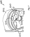
- FIG. 1 to 5 , 6, 7 to 9 and 12 are shown essentially three different versions 100, 101 and 601 of a sanitary fitting according to the invention and some of its components.
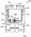
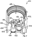
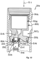
- the sanitary fittings 100, 101 and 601 have a in the 1 , 6 , 7 to 9 and 12 represented Fitting housing 102, 602, which has a housing interior 103, 603. While in accordance with the sanitary fitting 100 6 the cartridge 106 is inserted directly into the housing interior 103 in the insertion direction Pf1 up to an insertion stop, a cartridge adapter 104, 604 is inserted into the housing interior 103, 603 of the sanitary fittings 101, 601, which has a cartridge receptacle 105 for inserting a cartridge 106.
- At least one fluid which can be, for example, warm water, cold water, boiling hot water and/or carbonated water, can be passed through the cartridge 106 from at least one inlet opening to at least one outlet opening of the cartridge 106 .
- the at least one fluid flowing through in the cartridge can be regulated, for example with regard to the required quantity and/or with regard to certain fluid properties.
- valve discs 620, 621 or other control elements can be provided in the cartridge 106, which can be operated by means of an actuating pin 107 that protrudes from the cartridge 106 and can be actuated, for example, by means of a handle that is not shown in detail.
- the at least one fluid is fed to the cartridge 106 via at least one flexible hose line 108, 608.
- This at least one hose line 108, 608 is in liquid-tight contact with a hose connection element 109, 609 of the hose line 108, 608 on the cartridge 106 or on the cartridge adapter 104, 604.
- the hose connection element 109 of the at least one hose line 108 in the holding position shown here passes through a reach-through opening 110 on the cartridge 106 (cf. 6 ) or on the cartridge adapter 104 ( 1 ). It's up to the cartridge 106 (cf. 6 ) or on the cartridge adapter 104 (cf.
- hose connection element 109 of the sanitary fittings 100, 101 held hose connection element 109 of the sanitary fittings 100, 101 with its free end bordering a hose opening 111, optionally with the intermediary or clamping of a ring seal 117, in a liquid-tight manner on the edge region of the cartridge 106 bordering an associated inlet opening, so that the fluid supplied in the hose line 108 can flow into the cartridge 106 via the hose opening 111 and the inlet opening of the cartridge without a leak in the flow guide between the hose line 108 and the cartridge 106 having to be feared.
- the hose connection element 109 of the at least one hose line 108 is secured in the direction Pf2 facing away from the cartridge 106 through the access opening 110 on the cartridge 106 or on the Cartridge adapter 104 held.
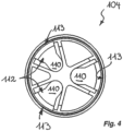
- the cartridge adapter 104 of the sanitary fitting 101 shown in more detail here is designed approximately in the shape of a pot and has, for example, three such access openings 110 at the bottom of its pot shape.
- the cartridge housing is also the in 6 cartridge 106 shown pot-shaped and also has three such access openings 110.
- an insertion slot 112 opens, which here is designed to be open towards an insertion opening 113 arranged on the outside on the circumference of the cartridge adapter 104 or the cartridge 106 .
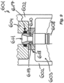
- the cartridge adapter 104 designed here in the shape of a pot or that is also pot-shaped configured cartridge housing of the cartridge 106 has, for example, three such access openings 110 at the bottom of its pot shape. Each of these reach-through openings 110 is assigned a hose connection element receptacle 114 which has a receiving shoulder 115 delimiting the reach-through opening 110 .
- the hose line 108 assigned to one of the reach-through openings 110 can be inserted through the insertion opening 113 and via the insertion slot 112 into the reach-through opening 110 in such a way that the hose connection element 109, with a cross-sectional enlargement embodied here as an annular flange 116 on the end face, is secured against the insertion direction Pf2 on the receiving shoulder 115 applied.
- the outer contour of the annular flange 116 is adapted in shape to the clear cross section of the hose connection element receptacle 114.
- the hose connection element 109 of the at least one hose line 108 is connected to the cartridge 106 or to the in the Figures 1 to 5 and 7 to 9
- the cartridge adapter 104 shown is held such that the end face of the annular flange 116 facing away from the hose line 108 is arranged below the plane formed by the inside of the cartridge housing or of the cartridge adapter 104 .
- a ring seal 117 can, for example, dip into the remaining recess of the hose connection element receptacle 114 and lateral slipping of the ring seal 117 is prevented.
- the hose connection element receptacle 114 has a cross-sectional enlargement adapted to the outer contour of the ring seal 117 in the area of the depression receiving the ring seal 117 .
- the ring seal 117 seals the hose opening 111 on the hose connection element 109 on the one hand and the opposite inlet opening on the cartridge, which is thus aligned in the direction of flow, on the other hand outwards.
- the hose connection element 109 and the adjacent inlet opening of the cartridge 106 can be sealed radially and/or axially by means of the ring seal 117 .
- the ring seal 117 designed here as a sealing ring, is clamped between the free front end of the hose connection element 109 surrounding the hose opening 111 and the adjacent edge area of the cartridge surrounding the associated inlet opening and axially seals the liquid flow in this area to the outside.
- the cartridge 106 in 12 a receiving cavity designed as a hose connection element receptacle, with the annular seal 117 being provided between the hose connection element 109 and the peripheral wall of the cartridge 106 surrounding the receiving cavity 12 shown embodiment, the liquid seal seals radially to the outside.
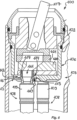
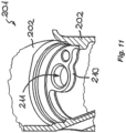
- the sanitary fitting 601 shown in the area of the longitudinally sectioned housing interior 603 of its fitting housing 602 has at least one access opening 610 which is provided on the inner circumference of the fitting housing 602.
- a hose line 608 is also secured against being pulled out of the reach-through opening 610 against the push-through direction Pf2.
- an insertion slot 612 opens, which has an insertion opening 613 at a slot end or slot portion spaced apart from the reach-through opening 610, which has an im
- Compared to reach-through opening 610 has an enlarged opening cross-section and/or--as here--is designed to be open at the edge.
- At least one retaining flange 618 projects into the housing interior on the inner circumference of the fitting housing 602, which retaining flange 618 has at least one of the reach-through openings 610 and the insertion slot 612 assigned to it, including the insertion opening 613 open towards the edge of the retaining flange 618.
- the at least one reach-through opening 610 is assigned a hose connection element receptacle 614, which has a receiving shoulder or a receiving bevel 619 delimiting the reach-through opening 610.
- the hose line 608 assigned to the reach-through opening 610 can thus be inserted through the insertion opening 613 via the insertion slot 612 into the reach-through opening 610 in such a way that the hose connection element 609 is secured with a cross-sectional enlargement counter to the push-through direction Pf2 on the receiving shoulder or - as here - on the receiving bevel 619 rests against the hose connection element receptacle 614.
- This cross-sectional enlargement provided at the free end of the hose connection element 609 is spherical or teardrop-shaped here.
- This teardrop-shaped configuration of the cross-sectional enlargement provided at the free end of the hose connection element 609 and the receiving bevel 619 acted upon by the cross-sectional enlargement allow misalignments of the hose connection element 609 and manufacturing tolerances to be compensated for.
- This compensation of misalignments and manufacturing tolerances is further promoted if the receiving bevel 619 has a spherical cap-shaped shape adapted to the spherical or teardrop shape of the cross-sectional enlargement provided on the tube element 609 .
- the sanitary fitting 601 shown is the hose connection element 609 of the at least one Hose line 608 and the adjacent inlet opening of the cartridge adapter 604 are sealed by means of a ring seal 617, with the hose connection element 609 here also resting with its free front end bordering the hose opening 611 on the edge region of the cartridge adapter 604 bordering the associated inlet opening.
- At least two hose lines 608, which are assigned to different fluids, for example cold water, warm water, boiling hot water or carbonated water, are also preferably held on the fitting housing 602 of the sanitary fitting 601.
Landscapes
- Engineering & Computer Science (AREA)
- General Engineering & Computer Science (AREA)
- Mechanical Engineering (AREA)
- Health & Medical Sciences (AREA)
- Life Sciences & Earth Sciences (AREA)
- Hydrology & Water Resources (AREA)
- Public Health (AREA)
- Water Supply & Treatment (AREA)
- Quick-Acting Or Multi-Walled Pipe Joints (AREA)
- Infusion, Injection, And Reservoir Apparatuses (AREA)
- Orthopedics, Nursing, And Contraception (AREA)
- Absorbent Articles And Supports Therefor (AREA)
Claims (15)
- Robinet sanitaire (100, 101, 601) comportant un corps de robinet (102, 602) qui possède un espace intérieur de corps (103, 603) dans lequel une cartouche (106) ou un adaptateur de cartouche (104, 604) avec une cartouche (106) prévue dans un réceptacle de cartouche (105) est inséré,laquelle cartouche (106) a au moins une ouverture d'admission qui est reliée à au moins une ouverture d'évacuation de la cartouche (106) pour permettre le passage d'au moins un fluide à travers la cartouche,et comportant au moins une conduite en tuyau (108, 608) pour permettre l'accès de l'au moins un fluide à la cartouche (106), laquelle conduite en tuyau (108, 608) présente au moins à son extrémité de tuyau orientée vers la cartouche (106) un élément de raccord de tuyau (109, 609), caractérisé en ce que l'élément de raccord de tuyau (109, 609) de l'au moins une conduite en tuyau (108, 608) est maintenu dans une position de maintien sur la cartouche (106) ou sur l'adaptateur de cartouche (104, 604), protégé contre un retrait de la conduite en tuyau (108, 608), et est appliqué avec son extrémité frontale libre délimitant une ouverture de tuyau (111) contre la zone périphérique de la cartouche (106) délimitant l'ouverture d'admission associée.
- Robinet sanitaire (100, 101) selon la revendication 1, caractérisé en ce que sur l'adaptateur de cartouche (104, 604) ou sur la cartouche (106) est prévue une ouverture de passage (110), que dans l'ouverture de passage (110) débouche une fente d'insertion (112) qui est ouverte au niveau d'une ouverture d'insertion (113) perpendiculairement à l'axe longitudinal de l'adaptateur de cartouche (104, 604) ou de la cartouche (106), qu'à l'au moins une ouverture de passage (110) est associé un réceptacle d'élément de raccord de tuyau (114) qui présente un ressaut de réception (115) délimitant l'ouverture de passage (110) ou une pente de réception, et que la conduite en tuyau (108) associée à l'ouverture de passage (110) peut être insérée à travers l'ouverture d'insertion (113) via la fente d'insertion (112) dans l'ouverture de passage (110) de telle sorte que l'élément de raccord de tuyau (109) est appliqué sur le ressaut de réception (115) ou sur la pente de réception, protégé contre un retrait de la conduite en tuyau par un élargissement de section transversale.
- Robinet sanitaire (601) selon le concept générique de la revendication 1, dans lequel l'élément de raccord de tuyau (609) de l'au moins une conduite en tuyau (608) traverse dans une position de maintien une ouverture de passage (610) sur le corps de robinet (602), caractérisé en ce que dans l'au moins une ouverture de passage (610) débouche une fente d'insertion (612) qui possède, à une extrémité de fente ou une portion de fente distante de l'ouverture de passage (610), une ouverture d'insertion (613) qui présente une section transversale d'ouverture agrandie par rapport à l'ouverture de passage (610) et/ou qui est ouverte sur le bord, qu'à l'au moins une ouverture de passage (610) est associé un réceptacle d'élément de raccord de tuyau (614) qui présente un ressaut de réception délimitant l'ouverture de passage (610) ou une pente de réception (619), et que la conduite en tuyau (608) associée à l'ouverture de passage (610) peut être insérée à travers l'ouverture d'insertion (613) via la fente d'insertion (612) dans l'ouverture de passage (610) de telle sorte que l'élément de raccord de tuyau (609) est appliqué sur le ressaut de réception ou sur la pente de réception (619), protégé contre un retrait de la conduite en tuyau (608) par un élargissement de section transversale et est appliqué avec son extrémité frontale libre délimitant une ouverture de tuyau contre la zone périphérique de la cartouche (106) ou de l'adaptateur de cartouche (604) délimitant l'ouverture d'admission associée.
- Robinet sanitaire (601) selon la revendication 3, caractérisé en ce que sur le pourtour de corps du corps de robinet (602) dépasse au moins une bride de maintien (618), laquelle bride de maintien (618) comporte au moins une des ouvertures de passage (610) ainsi que la fente d'insertion (612) avec l'ouverture d'insertion (613) qui lui est associée.
- Robinet sanitaire (100, 101) selon la revendication 2, caractérisé en ce que l'élargissement de section transversale sur l'au moins un élément de raccord de tuyau est configuré comme un ressaut annulaire ou comme une bride annulaire (116).
- Robinet sanitaire (100, 101) selon la revendication 5, caractérisé en ce que la bride annulaire (116) ou l'élargissement de section transversale de celle-ci est de forme adaptée, au niveau de son contour extérieur, à la section transversale intérieure du réceptacle d'élément de raccord de tuyau (114).
- Robinet sanitaire (100, 101, 601) selon une des revendications 1 à 6, caractérisé en ce que l'élément de raccord de tuyau (109, 609) de l'au moins une conduite en tuyau (108, 608) est maintenu de telle sorte sur la cartouche (106), sur l'adaptateur de cartouche (104) ou sur la bride de maintien (618) que la face frontale de la bride annulaire (116) éloignée de la conduite en tuyau (108, 608) est disposée à peu près dans ou sous le niveau formé par la face intérieure de la cartouche (106), de l'adaptateur de cartouche (104) ou de la bride de maintien (618).
- Robinet sanitaire (601) selon une des revendications 1 à 7, caractérisé en ce que l'élément de raccord de tuyau (609) est configuré en forme de bille ou de goutte à son extrémité libre.
- Robinet sanitaire (601) selon la revendication 8, caractérisé en ce que la pente de réception (619) est configurée en forme de calotte sphérique pour recevoir l'élément de raccord de tuyau (609) en forme de bille ou de goutte.
- Robinet sanitaire (100, 101, 601) selon une des revendications 1 à 9, caractérisé en ce que l'élément de raccord de tuyau (109, 609) et l'ouverture d'admission voisine de la cartouche (106) sont étanchéifiés au moyen d'un joint annulaire (117, 617).
- Robinet sanitaire (101) selon la revendication 10 et 2, caractérisé en ce que le joint annulaire (117) plonge par endroits dans le réceptacle d'élément de raccord de tuyau (114) associé de telle sorte que le joint annulaire (117) est sécurisé dans le réceptacle d'élément de raccord de tuyau (114).
- Robinet sanitaire (100, 101, 601) selon une des revendications 1 à 11, caractérisé en ce qu'au moins deux conduites en tuyau (108, 608) sont maintenues sur la cartouche (106), sur l'adaptateur de cartouche (104) ou sur le corps de robinet (602).
- Robinet sanitaire (100, 101, 601) selon une des revendications 1 à 12, caractérisé en ce que l'élément de raccord de tuyau (109) et l'ouverture d'admission voisine de la cartouche (106) sont étanchéifiés radialement et/ou axialement au moyen d'un joint annulaire (117).
- Robinet sanitaire (100, 101, 601) selon une des revendications 5 à 13, caractérisé en ce qu'entre la face frontale libre de l'élément de raccord de tuyau (109) délimitant l'ouverture de tuyau et la zone périphérique de la cartouche délimitant l'ouverture d'admission associée est serrée une bague d'étanchéité configurée comme un joint annulaire (117).
- Robinet sanitaire (100, 101, 601) selon une des revendications 10 à 14, caractérisé en ce que la cartouche (106) présente une cavité de réception configurée comme un réceptacle d'élément de raccord de tuyau et que le joint annulaire (117) est prévu entre l'élément de raccord de tuyau (109) et la paroi périphérique de la cartouche (106) délimitant la cavité de réception.
Applications Claiming Priority (2)
| Application Number | Priority Date | Filing Date | Title |
|---|---|---|---|
| DE202019106666.0U DE202019106666U1 (de) | 2019-11-29 | 2019-11-29 | Sanitärarmatur |
| PCT/EP2020/083542 WO2021105302A1 (fr) | 2019-11-29 | 2020-11-26 | Robinetterie sanitaire |
Publications (2)
| Publication Number | Publication Date |
|---|---|
| EP4058638A1 EP4058638A1 (fr) | 2022-09-21 |
| EP4058638B1 true EP4058638B1 (fr) | 2023-05-31 |
Family
ID=73642892
Family Applications (1)
| Application Number | Title | Priority Date | Filing Date |
|---|---|---|---|
| EP20816152.1A Active EP4058638B1 (fr) | 2019-11-29 | 2020-11-26 | Robinetterie sanitaire |
Country Status (6)
| Country | Link |
|---|---|
| US (1) | US12352020B2 (fr) |
| EP (1) | EP4058638B1 (fr) |
| CN (1) | CN114761644B (fr) |
| DE (1) | DE202019106666U1 (fr) |
| ES (1) | ES2948514T3 (fr) |
| WO (1) | WO2021105302A1 (fr) |
Families Citing this family (2)
| Publication number | Priority date | Publication date | Assignee | Title |
|---|---|---|---|---|
| DE202020106539U1 (de) * | 2020-11-13 | 2022-02-17 | Neoperl Gmbh | Multilumen |
| US20240059473A1 (en) * | 2022-08-16 | 2024-02-22 | Mixxy Products, Llc | Modular systems and devices for combining fluids |
Citations (8)
| Publication number | Priority date | Publication date | Assignee | Title |
|---|---|---|---|---|
| DE19911066A1 (de) * | 1999-03-12 | 2000-09-14 | Hansgrohe Ag | Sanitärarmatur und Montageverfahren |
| EP1435480B1 (fr) * | 2002-12-30 | 2011-09-14 | Hansgrohe AG | Robinetterie sanitaire |
| DE202013002188U1 (de) * | 2013-03-08 | 2014-06-11 | Neoperl Gmbh | Sanitäres Einbauteil, Innenschlauchanordnung für eine Sanitärarmatur und Sanitärarmatur |
| US20140251451A1 (en) * | 2013-10-29 | 2014-09-11 | Globe Union Industrial Corp. | Positioning structure of water supply hose for pull-out faucet |
| EP2778300A1 (fr) * | 2013-03-15 | 2014-09-17 | Kohler Co. | Ensemble vanne de mélange pour robinet |
| EP1798348B1 (fr) * | 2005-12-19 | 2017-07-12 | Grohe AG | Robinet mélangeur |
| EP2497866B1 (fr) * | 2011-03-11 | 2019-08-21 | Ideal Standard International NV | Robinet doté d'une sortie orientable |
| EP2995838B1 (fr) * | 2013-05-08 | 2019-11-20 | Nippon Pillar Packing Co., Ltd. | Bague interne |
Family Cites Families (17)
| Publication number | Priority date | Publication date | Assignee | Title |
|---|---|---|---|---|
| DE3119313C2 (de) | 1981-05-15 | 1985-10-03 | Hansa Metallwerke Ag, 7000 Stuttgart | Sanitärarmatur |
| DE3141475C2 (de) * | 1981-10-20 | 1986-10-02 | Gewerkschaft Eisenhütte Westfalia, 4670 Lünen | Schlauchkupplung für mehradrige hydraulische Kabel zur Verwendung bei hydraulischen Ausbausystemen in Bergbaubetrieben |
| DE19527985A1 (de) | 1995-07-31 | 1997-02-06 | Grohe Armaturen Friedrich | Mischbatterie |
| US6484953B2 (en) | 2001-02-06 | 2002-11-26 | Kohler Co. | Water spout with removable laminar flow cartridge |
| DE10234206A1 (de) * | 2002-07-19 | 2004-01-29 | Hansgrohe Ag | Steckverbindung für Sanitärarmaturen |
| DE10311801A1 (de) | 2003-03-12 | 2004-09-23 | Hansgrohe Ag | Einrichtung zum Befestigen einer Leitung |
| DE10330685A1 (de) | 2003-07-08 | 2005-02-03 | Kludi Gmbh & Co. Kg | Formschlüssige Verbindung des Anschlussstücks einer Rohrleitung |
| JP4594714B2 (ja) | 2004-12-07 | 2010-12-08 | サンデン株式会社 | 配管継手構造およびその製造方法 |
| EP2220297B1 (fr) | 2007-11-19 | 2011-08-17 | Kludi GmbH & Co. KG | Élément de fixation de tuyau souple pour une robinetterie sanitaire ou de cuisine |
| DE102010023962A1 (de) * | 2010-06-16 | 2011-12-22 | Neoperl Gmbh | Dichtring, Durchflussmengenregler sowie Brausearmatur mit einem Durchflussmengenregler |
| TWI504830B (zh) | 2013-10-31 | 2015-10-21 | Yi Jhong Dev Co Ltd | The quick connector structure of the cleaner |
| DE202014101116U1 (de) | 2014-03-12 | 2014-04-07 | Flühs Drehtechnik GmbH | Sanitärarmatur |
| DE202017100423U1 (de) | 2017-01-26 | 2018-04-27 | Neoperl Gmbh | Schlauchanschlussanordnung, Verwendung einer Schlauchanschlussanordnung und Sanitärarmatur |
| DE102017101566B3 (de) * | 2017-01-26 | 2018-06-28 | Neoperl Gmbh | Schlauchanschlussanordnung, Verwendung einer Schlauchanschlussanordnung und Sanitärarmatur |
| GB201710279D0 (en) | 2017-06-28 | 2017-08-09 | Ge Healthcare Bio Sciences Ab | Improvements in and relating to bioprocessing equipment and fluid couplings therefor |
| SE542174C2 (en) * | 2018-07-04 | 2020-03-10 | Villeroy & Boch Gustavsberg Ab | A fluid distribution assembly for a faucet and a faucet |
| CN209041741U (zh) | 2018-08-20 | 2019-06-28 | 路达(厦门)工业有限公司 | 一种抽取式龙头 |
-
2019
- 2019-11-29 DE DE202019106666.0U patent/DE202019106666U1/de active Active
-
2020
- 2020-11-26 CN CN202080082666.XA patent/CN114761644B/zh active Active
- 2020-11-26 US US17/779,745 patent/US12352020B2/en active Active
- 2020-11-26 ES ES20816152T patent/ES2948514T3/es active Active
- 2020-11-26 WO PCT/EP2020/083542 patent/WO2021105302A1/fr not_active Ceased
- 2020-11-26 EP EP20816152.1A patent/EP4058638B1/fr active Active
Patent Citations (8)
| Publication number | Priority date | Publication date | Assignee | Title |
|---|---|---|---|---|
| DE19911066A1 (de) * | 1999-03-12 | 2000-09-14 | Hansgrohe Ag | Sanitärarmatur und Montageverfahren |
| EP1435480B1 (fr) * | 2002-12-30 | 2011-09-14 | Hansgrohe AG | Robinetterie sanitaire |
| EP1798348B1 (fr) * | 2005-12-19 | 2017-07-12 | Grohe AG | Robinet mélangeur |
| EP2497866B1 (fr) * | 2011-03-11 | 2019-08-21 | Ideal Standard International NV | Robinet doté d'une sortie orientable |
| DE202013002188U1 (de) * | 2013-03-08 | 2014-06-11 | Neoperl Gmbh | Sanitäres Einbauteil, Innenschlauchanordnung für eine Sanitärarmatur und Sanitärarmatur |
| EP2778300A1 (fr) * | 2013-03-15 | 2014-09-17 | Kohler Co. | Ensemble vanne de mélange pour robinet |
| EP2995838B1 (fr) * | 2013-05-08 | 2019-11-20 | Nippon Pillar Packing Co., Ltd. | Bague interne |
| US20140251451A1 (en) * | 2013-10-29 | 2014-09-11 | Globe Union Industrial Corp. | Positioning structure of water supply hose for pull-out faucet |
Also Published As
| Publication number | Publication date |
|---|---|
| DE202019106666U1 (de) | 2021-03-03 |
| CN114761644B (zh) | 2025-03-21 |
| EP4058638A1 (fr) | 2022-09-21 |
| WO2021105302A1 (fr) | 2021-06-03 |
| US12352020B2 (en) | 2025-07-08 |
| ES2948514T3 (es) | 2023-09-13 |
| US20230003006A1 (en) | 2023-01-05 |
| CN114761644A (zh) | 2022-07-15 |
Similar Documents
| Publication | Publication Date | Title |
|---|---|---|
| WO2005077543A1 (fr) | Recipient a ecoulement pour pistolet pulverisateur de peinture | |
| DE112017000317T5 (de) | Mischeineit, mit diesem verbundenen Wasserhahn mit Mischbatterie und Verfahren zur Herstellung eines derartigen Wasserhahns mit Mischbatterie | |
| DE2211046B2 (de) | Regeleinrichtung für einen mit einem Strömungssystem verbundenen Wärmetauscher, insbesondere für einen Heizkörper | |
| EP4058638B1 (fr) | Robinetterie sanitaire | |
| EP2988043B1 (fr) | Pièce de raccordement avec ventilateur à membrane élastomère | |
| DE10324307B3 (de) | Schnellkupplungseinheit mit integriertem Rückschlagventil | |
| DE2328361A1 (de) | Mischarmatur, insbesondere wasserhahn fuer warmes und kaltes wasser | |
| DE202017103194U1 (de) | Sanitärventil | |
| EP1707692B1 (fr) | Robinet pourvu d'un bec téléscopique | |
| EP3105380B1 (fr) | Robinet à bec pivotant | |
| DE4421387B4 (de) | Einlochmischbatterie | |
| DE102013205250B9 (de) | Rohranschlussadapter und Sanitärarmatur | |
| EP3105381B1 (fr) | Robinet à bec pivotant | |
| DE102007009409B4 (de) | Armatur mit Schwenkauslauf | |
| EP1818461A1 (fr) | Armature sanitaire | |
| EP0899452A2 (fr) | Filtre pour liquides pour filtrer du carburant | |
| EP4060133A1 (fr) | Agencement de soupape, utilisation et série correspondantes | |
| DE102019132475A1 (de) | Sanitärarmatur | |
| EP3931474B1 (fr) | Robinet avec tuyau extensible | |
| DE102015226383A1 (de) | Sanitäre Auslaufarmatur | |
| DE102007014251A1 (de) | Sanitärarmatur | |
| EP3112540A1 (fr) | Partie superieure de soupape | |
| DE19930623A1 (de) | Ventilkartuschenbefestigung | |
| DE4443895A1 (de) | Sanitärarmatur | |
| EP1650362B1 (fr) | Aérateur de tuyaux et soupape d'arrêt |
Legal Events
| Date | Code | Title | Description |
|---|---|---|---|
| STAA | Information on the status of an ep patent application or granted ep patent |
Free format text: STATUS: UNKNOWN |
|
| STAA | Information on the status of an ep patent application or granted ep patent |
Free format text: STATUS: THE INTERNATIONAL PUBLICATION HAS BEEN MADE |
|
| PUAI | Public reference made under article 153(3) epc to a published international application that has entered the european phase |
Free format text: ORIGINAL CODE: 0009012 |
|
| STAA | Information on the status of an ep patent application or granted ep patent |
Free format text: STATUS: REQUEST FOR EXAMINATION WAS MADE |
|
| 17P | Request for examination filed |
Effective date: 20220617 |
|
| AK | Designated contracting states |
Kind code of ref document: A1 Designated state(s): AL AT BE BG CH CY CZ DE DK EE ES FI FR GB GR HR HU IE IS IT LI LT LU LV MC MK MT NL NO PL PT RO RS SE SI SK SM TR |
|
| GRAP | Despatch of communication of intention to grant a patent |
Free format text: ORIGINAL CODE: EPIDOSNIGR1 |
|
| STAA | Information on the status of an ep patent application or granted ep patent |
Free format text: STATUS: GRANT OF PATENT IS INTENDED |
|
| DAV | Request for validation of the european patent (deleted) | ||
| DAX | Request for extension of the european patent (deleted) | ||
| INTG | Intention to grant announced |
Effective date: 20221209 |
|
| GRAS | Grant fee paid |
Free format text: ORIGINAL CODE: EPIDOSNIGR3 |
|
| GRAA | (expected) grant |
Free format text: ORIGINAL CODE: 0009210 |
|
| STAA | Information on the status of an ep patent application or granted ep patent |
Free format text: STATUS: THE PATENT HAS BEEN GRANTED |
|
| AK | Designated contracting states |
Kind code of ref document: B1 Designated state(s): AL AT BE BG CH CY CZ DE DK EE ES FI FR GB GR HR HU IE IS IT LI LT LU LV MC MK MT NL NO PL PT RO RS SE SI SK SM TR |
|
| REG | Reference to a national code |
Ref country code: GB Ref legal event code: FG4D Free format text: NOT ENGLISH Ref country code: CH Ref legal event code: EP |
|
| REG | Reference to a national code |
Ref country code: AT Ref legal event code: REF Ref document number: 1570988 Country of ref document: AT Kind code of ref document: T Effective date: 20230615 Ref country code: DE Ref legal event code: R096 Ref document number: 502020003406 Country of ref document: DE |
|
| REG | Reference to a national code |
Ref country code: IE Ref legal event code: FG4D Free format text: LANGUAGE OF EP DOCUMENT: GERMAN |
|
| REG | Reference to a national code |
Ref country code: ES Ref legal event code: FG2A Ref document number: 2948514 Country of ref document: ES Kind code of ref document: T3 Effective date: 20230913 |
|
| REG | Reference to a national code |
Ref country code: LT Ref legal event code: MG9D |
|
| REG | Reference to a national code |
Ref country code: NL Ref legal event code: MP Effective date: 20230531 |
|
| PG25 | Lapsed in a contracting state [announced via postgrant information from national office to epo] |
Ref country code: SE Free format text: LAPSE BECAUSE OF FAILURE TO SUBMIT A TRANSLATION OF THE DESCRIPTION OR TO PAY THE FEE WITHIN THE PRESCRIBED TIME-LIMIT Effective date: 20230531 Ref country code: NO Free format text: LAPSE BECAUSE OF FAILURE TO SUBMIT A TRANSLATION OF THE DESCRIPTION OR TO PAY THE FEE WITHIN THE PRESCRIBED TIME-LIMIT Effective date: 20230831 |
|
| PG25 | Lapsed in a contracting state [announced via postgrant information from national office to epo] |
Ref country code: RS Free format text: LAPSE BECAUSE OF FAILURE TO SUBMIT A TRANSLATION OF THE DESCRIPTION OR TO PAY THE FEE WITHIN THE PRESCRIBED TIME-LIMIT Effective date: 20230531 Ref country code: PL Free format text: LAPSE BECAUSE OF FAILURE TO SUBMIT A TRANSLATION OF THE DESCRIPTION OR TO PAY THE FEE WITHIN THE PRESCRIBED TIME-LIMIT Effective date: 20230531 Ref country code: NL Free format text: LAPSE BECAUSE OF FAILURE TO SUBMIT A TRANSLATION OF THE DESCRIPTION OR TO PAY THE FEE WITHIN THE PRESCRIBED TIME-LIMIT Effective date: 20230531 Ref country code: LV Free format text: LAPSE BECAUSE OF FAILURE TO SUBMIT A TRANSLATION OF THE DESCRIPTION OR TO PAY THE FEE WITHIN THE PRESCRIBED TIME-LIMIT Effective date: 20230531 Ref country code: LT Free format text: LAPSE BECAUSE OF FAILURE TO SUBMIT A TRANSLATION OF THE DESCRIPTION OR TO PAY THE FEE WITHIN THE PRESCRIBED TIME-LIMIT Effective date: 20230531 Ref country code: IS Free format text: LAPSE BECAUSE OF FAILURE TO SUBMIT A TRANSLATION OF THE DESCRIPTION OR TO PAY THE FEE WITHIN THE PRESCRIBED TIME-LIMIT Effective date: 20230930 Ref country code: HR Free format text: LAPSE BECAUSE OF FAILURE TO SUBMIT A TRANSLATION OF THE DESCRIPTION OR TO PAY THE FEE WITHIN THE PRESCRIBED TIME-LIMIT Effective date: 20230531 Ref country code: GR Free format text: LAPSE BECAUSE OF FAILURE TO SUBMIT A TRANSLATION OF THE DESCRIPTION OR TO PAY THE FEE WITHIN THE PRESCRIBED TIME-LIMIT Effective date: 20230901 |
|
| PG25 | Lapsed in a contracting state [announced via postgrant information from national office to epo] |
Ref country code: FI Free format text: LAPSE BECAUSE OF FAILURE TO SUBMIT A TRANSLATION OF THE DESCRIPTION OR TO PAY THE FEE WITHIN THE PRESCRIBED TIME-LIMIT Effective date: 20230531 |
|
| PG25 | Lapsed in a contracting state [announced via postgrant information from national office to epo] |
Ref country code: SK Free format text: LAPSE BECAUSE OF FAILURE TO SUBMIT A TRANSLATION OF THE DESCRIPTION OR TO PAY THE FEE WITHIN THE PRESCRIBED TIME-LIMIT Effective date: 20230531 |
|
| PG25 | Lapsed in a contracting state [announced via postgrant information from national office to epo] |
Ref country code: SM Free format text: LAPSE BECAUSE OF FAILURE TO SUBMIT A TRANSLATION OF THE DESCRIPTION OR TO PAY THE FEE WITHIN THE PRESCRIBED TIME-LIMIT Effective date: 20230531 Ref country code: SK Free format text: LAPSE BECAUSE OF FAILURE TO SUBMIT A TRANSLATION OF THE DESCRIPTION OR TO PAY THE FEE WITHIN THE PRESCRIBED TIME-LIMIT Effective date: 20230531 Ref country code: RO Free format text: LAPSE BECAUSE OF FAILURE TO SUBMIT A TRANSLATION OF THE DESCRIPTION OR TO PAY THE FEE WITHIN THE PRESCRIBED TIME-LIMIT Effective date: 20230531 Ref country code: PT Free format text: LAPSE BECAUSE OF FAILURE TO SUBMIT A TRANSLATION OF THE DESCRIPTION OR TO PAY THE FEE WITHIN THE PRESCRIBED TIME-LIMIT Effective date: 20231002 Ref country code: EE Free format text: LAPSE BECAUSE OF FAILURE TO SUBMIT A TRANSLATION OF THE DESCRIPTION OR TO PAY THE FEE WITHIN THE PRESCRIBED TIME-LIMIT Effective date: 20230531 Ref country code: DK Free format text: LAPSE BECAUSE OF FAILURE TO SUBMIT A TRANSLATION OF THE DESCRIPTION OR TO PAY THE FEE WITHIN THE PRESCRIBED TIME-LIMIT Effective date: 20230531 Ref country code: CZ Free format text: LAPSE BECAUSE OF FAILURE TO SUBMIT A TRANSLATION OF THE DESCRIPTION OR TO PAY THE FEE WITHIN THE PRESCRIBED TIME-LIMIT Effective date: 20230531 |
|
| REG | Reference to a national code |
Ref country code: DE Ref legal event code: R097 Ref document number: 502020003406 Country of ref document: DE |
|
| PLBE | No opposition filed within time limit |
Free format text: ORIGINAL CODE: 0009261 |
|
| STAA | Information on the status of an ep patent application or granted ep patent |
Free format text: STATUS: NO OPPOSITION FILED WITHIN TIME LIMIT |
|
| PG25 | Lapsed in a contracting state [announced via postgrant information from national office to epo] |
Ref country code: SI Free format text: LAPSE BECAUSE OF FAILURE TO SUBMIT A TRANSLATION OF THE DESCRIPTION OR TO PAY THE FEE WITHIN THE PRESCRIBED TIME-LIMIT Effective date: 20230531 |
|
| 26N | No opposition filed |
Effective date: 20240301 |
|
| PG25 | Lapsed in a contracting state [announced via postgrant information from national office to epo] |
Ref country code: SI Free format text: LAPSE BECAUSE OF FAILURE TO SUBMIT A TRANSLATION OF THE DESCRIPTION OR TO PAY THE FEE WITHIN THE PRESCRIBED TIME-LIMIT Effective date: 20230531 |
|
| REG | Reference to a national code |
Ref country code: CH Ref legal event code: PL |
|
| PG25 | Lapsed in a contracting state [announced via postgrant information from national office to epo] |
Ref country code: MC Free format text: LAPSE BECAUSE OF FAILURE TO SUBMIT A TRANSLATION OF THE DESCRIPTION OR TO PAY THE FEE WITHIN THE PRESCRIBED TIME-LIMIT Effective date: 20230531 |
|
| PG25 | Lapsed in a contracting state [announced via postgrant information from national office to epo] |
Ref country code: LU Free format text: LAPSE BECAUSE OF NON-PAYMENT OF DUE FEES Effective date: 20231126 |
|
| PG25 | Lapsed in a contracting state [announced via postgrant information from national office to epo] |
Ref country code: CH Free format text: LAPSE BECAUSE OF NON-PAYMENT OF DUE FEES Effective date: 20231130 |
|
| PG25 | Lapsed in a contracting state [announced via postgrant information from national office to epo] |
Ref country code: MC Free format text: LAPSE BECAUSE OF FAILURE TO SUBMIT A TRANSLATION OF THE DESCRIPTION OR TO PAY THE FEE WITHIN THE PRESCRIBED TIME-LIMIT Effective date: 20230531 Ref country code: LU Free format text: LAPSE BECAUSE OF NON-PAYMENT OF DUE FEES Effective date: 20231126 Ref country code: CH Free format text: LAPSE BECAUSE OF NON-PAYMENT OF DUE FEES Effective date: 20231130 |
|
| REG | Reference to a national code |
Ref country code: BE Ref legal event code: MM Effective date: 20231130 |
|
| REG | Reference to a national code |
Ref country code: IE Ref legal event code: MM4A |
|
| PG25 | Lapsed in a contracting state [announced via postgrant information from national office to epo] |
Ref country code: IE Free format text: LAPSE BECAUSE OF NON-PAYMENT OF DUE FEES Effective date: 20231126 |
|
| PG25 | Lapsed in a contracting state [announced via postgrant information from national office to epo] |
Ref country code: BE Free format text: LAPSE BECAUSE OF NON-PAYMENT OF DUE FEES Effective date: 20231130 |
|
| PG25 | Lapsed in a contracting state [announced via postgrant information from national office to epo] |
Ref country code: FR Free format text: LAPSE BECAUSE OF NON-PAYMENT OF DUE FEES Effective date: 20231130 |
|
| PG25 | Lapsed in a contracting state [announced via postgrant information from national office to epo] |
Ref country code: IE Free format text: LAPSE BECAUSE OF NON-PAYMENT OF DUE FEES Effective date: 20231126 Ref country code: FR Free format text: LAPSE BECAUSE OF NON-PAYMENT OF DUE FEES Effective date: 20231130 Ref country code: BE Free format text: LAPSE BECAUSE OF NON-PAYMENT OF DUE FEES Effective date: 20231130 |
|
| PG25 | Lapsed in a contracting state [announced via postgrant information from national office to epo] |
Ref country code: BG Free format text: LAPSE BECAUSE OF FAILURE TO SUBMIT A TRANSLATION OF THE DESCRIPTION OR TO PAY THE FEE WITHIN THE PRESCRIBED TIME-LIMIT Effective date: 20230531 |
|
| PG25 | Lapsed in a contracting state [announced via postgrant information from national office to epo] |
Ref country code: BG Free format text: LAPSE BECAUSE OF FAILURE TO SUBMIT A TRANSLATION OF THE DESCRIPTION OR TO PAY THE FEE WITHIN THE PRESCRIBED TIME-LIMIT Effective date: 20230531 |
|
| GBPC | Gb: european patent ceased through non-payment of renewal fee |
Effective date: 20241126 |
|
| PG25 | Lapsed in a contracting state [announced via postgrant information from national office to epo] |
Ref country code: CY Free format text: LAPSE BECAUSE OF FAILURE TO SUBMIT A TRANSLATION OF THE DESCRIPTION OR TO PAY THE FEE WITHIN THE PRESCRIBED TIME-LIMIT; INVALID AB INITIO Effective date: 20201126 |
|
| PG25 | Lapsed in a contracting state [announced via postgrant information from national office to epo] |
Ref country code: HU Free format text: LAPSE BECAUSE OF FAILURE TO SUBMIT A TRANSLATION OF THE DESCRIPTION OR TO PAY THE FEE WITHIN THE PRESCRIBED TIME-LIMIT; INVALID AB INITIO Effective date: 20201126 |
|
| PG25 | Lapsed in a contracting state [announced via postgrant information from national office to epo] |
Ref country code: GB Free format text: LAPSE BECAUSE OF NON-PAYMENT OF DUE FEES Effective date: 20241126 |
|
| PGFP | Annual fee paid to national office [announced via postgrant information from national office to epo] |
Ref country code: AT Payment date: 20260113 Year of fee payment: 5 |
|
| PGFP | Annual fee paid to national office [announced via postgrant information from national office to epo] |
Ref country code: IT Payment date: 20251128 Year of fee payment: 6 |
|
| PGFP | Annual fee paid to national office [announced via postgrant information from national office to epo] |
Ref country code: TR Payment date: 20251120 Year of fee payment: 6 |
|
| PGFP | Annual fee paid to national office [announced via postgrant information from national office to epo] |
Ref country code: ES Payment date: 20251216 Year of fee payment: 6 |
|
| PGFP | Annual fee paid to national office [announced via postgrant information from national office to epo] |
Ref country code: DE Payment date: 20260128 Year of fee payment: 6 |