EP1632702B1 - Robinet mitigeur - Google Patents
Robinet mitigeur Download PDFInfo
- Publication number
- EP1632702B1 EP1632702B1 EP05018228A EP05018228A EP1632702B1 EP 1632702 B1 EP1632702 B1 EP 1632702B1 EP 05018228 A EP05018228 A EP 05018228A EP 05018228 A EP05018228 A EP 05018228A EP 1632702 B1 EP1632702 B1 EP 1632702B1
- Authority
- EP
- European Patent Office
- Prior art keywords
- thermostat
- valve seat
- valve according
- mixer valve
- seat slider
- Prior art date
- Legal status (The legal status is an assumption and is not a legal conclusion. Google has not performed a legal analysis and makes no representation as to the accuracy of the status listed.)
- Active
Links
- XLYOFNOQVPJJNP-UHFFFAOYSA-N water Substances O XLYOFNOQVPJJNP-UHFFFAOYSA-N 0.000 claims abstract description 42
- 238000011144 upstream manufacturing Methods 0.000 claims description 3
- 229920003023 plastic Polymers 0.000 claims description 2
- 239000004033 plastic Substances 0.000 claims description 2
- 239000000463 material Substances 0.000 claims 1
- 230000001419 dependent effect Effects 0.000 abstract 1
- 229920001971 elastomer Polymers 0.000 abstract 1
- 239000000806 elastomer Substances 0.000 abstract 1
- 230000000717 retained effect Effects 0.000 abstract 1
- 238000004519 manufacturing process Methods 0.000 description 3
- 230000006835 compression Effects 0.000 description 2
- 238000007906 compression Methods 0.000 description 2
- 238000013459 approach Methods 0.000 description 1
- 239000000203 mixture Substances 0.000 description 1
- 238000003908 quality control method Methods 0.000 description 1
- 238000007789 sealing Methods 0.000 description 1
Images

Classifications
-
- G—PHYSICS
- G05—CONTROLLING; REGULATING
- G05D—SYSTEMS FOR CONTROLLING OR REGULATING NON-ELECTRIC VARIABLES
- G05D23/00—Control of temperature
- G05D23/01—Control of temperature without auxiliary power
- G05D23/13—Control of temperature without auxiliary power by varying the mixing ratio of two fluids having different temperatures
- G05D23/1306—Control of temperature without auxiliary power by varying the mixing ratio of two fluids having different temperatures for liquids
- G05D23/132—Control of temperature without auxiliary power by varying the mixing ratio of two fluids having different temperatures for liquids with temperature sensing element
- G05D23/134—Control of temperature without auxiliary power by varying the mixing ratio of two fluids having different temperatures for liquids with temperature sensing element measuring the temperature of mixed fluid
- G05D23/1346—Control of temperature without auxiliary power by varying the mixing ratio of two fluids having different temperatures for liquids with temperature sensing element measuring the temperature of mixed fluid with manual temperature setting means
Definitions
- the invention relates to a mixing valve for cold and hot water with thermostatic control of the mixed water temperature according to the preamble of réelles1.
- the invention has for its object to improve the mixing valve specified in the preamble of claim 1 and in particular form so that a more cost-effective production and accurate assembly is possible.
- This object is achieved in a generic mixing valve characterized in that between the double valve seat slide and the thermostat via a rubber-elastic ring an axially and radially backlash-free connection is provided. Further embodiments of the invention are specified in claims 2 to 11.
- the double valve seat slide can be provided with an inwardly projecting flange which engages in the inserted position radially between the snap ring and the rubber-elastic ring.
- the end face of the thermostat may be conical.
- the mixing valve taken in the mixing valve to achieve a particularly high quality control behind the inflow the cold water and hot water from separate openings in the double valve seat slide and mixed when passing through a provided on the double valve slide separating sleeve to tempered mixed water and delivered to the thermostat is, can be achieved with the rubber-elastic ring at the same time sealing the cold water area to the temperature sensor of the thermostat.
- the separate openings at the two end faces of the double valve seat slide can be suitably designed as inclined slots which meet in the wall of the separating sleeve and a ring slot-shaped passage of the mixed cold and hot water to the upstream region of the Relay temperature sensor of the thermostat, so that the double valve seat slide can be inexpensively manufactured in one piece from plastic.
- the slanted slots can be conveniently arranged inclined at an angle of 20 ° to 50 ° to the central axis.
- four symmetrically arranged annular segment-shaped oblique slots are provided on each of the two end faces.
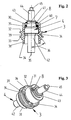
- the thermostatically controlled mixing valve shown in FIG. 1 contains a housing 1 with a cold water inlet 10, a hot water inlet 11 and a mixed water outlet 12.
- a valve cartridge housing 2 of a valve cartridge is sealed in a receiving bore 13.
- an eyebolt 14 is provided in the housing 1 by means of a thread.
- the valve cartridge housing 2 is closed at the downstream end region with a cover 21.
- an inlet cross section 22 which is in communication with the cold water inlet 10, and an inlet cross section 23, which communicates with the hot water inlet 11, is provided.
- a shoulder 24 is designed as a cold water valve seat and on the cover 21, a shoulder 25 as a hot water valve seat.
- a double valve seat slide 3 is arranged, the two parallel arranged end faces 32, 33, the two inlet cross-sections 22, 23 determine. In an axial movement of the double valve seat slide 3 relative to the valve cartridge housing 2 thus change the two inlet cross-sections 22, 23 in opposite directions.
- a separating sleeve 31 is formed with a reduced diameter in each case on an end face 32, 33.
- the separating sleeve 31 With the separating sleeve 31, the respectively depending on the inlet cross-sections 22, 23 metered supplied cold water and hot water from the thermostat 4 is shielded.
- the separating sleeve is sealed on the one hand via an O-ring 37 to the inner wall of the lid 21 and on the other hand with a rubber-elastic ring 7 to the thermostat 4.
- O-ring 37 to the inner wall of the lid 21
- a rubber-elastic ring 7 to the thermostat 4.
- a arranged in an annular groove 39 of the double valve seat slide 3 O-ring which rests sealingly in the inner wall of the valve cartridge housing 2, the cold water inflow space separated from the hot water inflow space.
- the inflowing cold water can thus flow only through arranged downstream of the double valve seat slide 3 in the end face 32 annular slanted 34 and the inflowing hot water only through downstream behind the double valve seat slide 3 in the region of the end face 33 arranged annular inclined slots 34.
- the oblique slits 34 in this case penetrate the separating sleeve 31 and unite shortly before emerging on the inner annular wall of the separating sleeve 31, so that in the region of the separating sleeve 31, a mixture of cold and hot water to tempered mixed water takes place, which then radially to the upstream region of a Temperature sensor 42 of Thermostat 4 emerges.
- the oblique slots 34 are formed inclined to the central axis 35 at an angle 36 of about 45 °, as can be seen in particular from Figure 2 of the drawing.
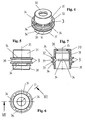
- the separating sleeve 31 has an inwardly projecting flange 30, which is formed so that the thermostat 4 can be inserted from the side with the enlarged opening in the separating sleeve 31 with the ring 7.
- the opening is provided with a reduced diameter portion 310 in the region of the flange 30, so that a radial compression takes place in the inserted position.
- the thermostat 4 with a projection 43 passes through the flange 30, whereby the rubber-elastic ring 7 can be pressed on the one hand by the flange 30 and on the other hand by a front side 40 of the thermostat 4.
- a snap ring 8 can then be inserted into an annular groove 41 of the thermostat 4 for axial securing.
- the double-seat valve slide 3 is thus kept free of play both radially and axially to the thermostat 4, as can be seen in particular from Figure 2 of the drawing.
- the axial fixation of the double valve seat slide 3 to the thermostat 4 is predetermined by the snap ring 8.
- the assembly shown in Figure 2 and 3 can be inserted axially with the cover 21 in the valve cartridge housing 2, wherein a pin 44 sealed out of the water acted upon space of the valve cartridge housing 2 is led out. Then, a return spring 6 is pushed against the downstream end face of the separating sleeve 31 and then the lid 21 is screwed into the valve cartridge housing 2 by means of thread. Thereafter, the so completed valve cartridge can be inserted with the valve cartridge housing 2 in the receiving bore 13 of the housing 1, wherein in the inserted position, the individual inflow channels are sealed by means of O-rings against each other and to the outside. To secure in the inserted position, the eye bolt 14 is screwed into the housing 1.
- a temperature selection device 5 is arranged non-rotatably but axially displaceable in the valve cartridge housing 2.
- a movement thread 50 is formed, with which a not shown in the drawing axially held on the valve cartridge housing 2 rotary handle with an adjusting nut is engaged, so that by a rotary movement of the control handle the Temperaturvor techlvorides 5 axially to the valve cartridge housing 2 is movable.
- the axial movement is transmitted via a plunger 45 to the thermostat 4 and the double-seat valve slide 3, so that in this way the setpoint temperature of the mixed water is adjustable.
Claims (11)
- Mitigeur pour eau froide et eau chaude avec réglage thermostatique de la température de l'eau sortant du robinet par un thermostat (4) positionné par un dispositif de présélection de la température (5) et relié à une vanne à double siège (3), disposée dans un boitier (1, 2) comportant au moins une arrivée d'eau froide et une arrivée d'eau chaude (10, 11) ainsi qu'au moins une sortie d'eau mélangée (12), les sections d'arrivée (22, 23) étant commandées en sens inverse sur deux fentes d'alimentation du mitigeur par le collier à double siège (3) avec ses deux faces avant (32, 33), la vanne à double siège (3) étant placée sur le thermostat (4), en butée axiale sur une face avant (40) et reliée au thermostat (4) par l'intermédiaire d'un circlip (8),
caractérisé par
une liaison axialement et radialement sans jeu entre la vanne à double siège (3) et le thermostat (4) par l'intermédiaire d'une bague en caoutchouc élastique (7). - Mitigeur selon la revendication 1,
caractérisé en ce qu'
une bride (30) en saillie vers l'intérieur est rapportée sur une zone tubulaire, entre le circlip (8) et la bague en caoutchouc élastique (7) sur la vanne à double siège (3). - Mitigeur selon la revendication 1 ou la revendication 2,
caractérisé en ce que
la face avant (40) du thermostat (4) est conique pour que la bague en caoutchouc élastique (7) puisse venir en butée. - Mitigeur selon au moins l'une des revendications précédentes,
caractérisé en ce que
le circlip (8) est logé dans une rainure annulaire (41) du thermostat (4). - Mitigeur selon au moins l'une des revendications précédentes,
dans lequel l'eau froide et l'eau chaude sont admises en aval des sections d'alimentation, dans la vanne à double siège (3) par des ouvertures séparées et mélangées lors du passage par un manchon de séparation (31), sur la vanne à double siège (3) en une eau tempérée délivrée en fonction du thermostat (4),
caractérisé en ce que
la bague en caoutchouc élastique (7) ferme hermétiquement la zone d'eau froide, limitée par le manchon de séparation (31) par rapport à la sonde thermique (42) du thermostat (5). - Mitigeur selon la revendication 5,
caractérisé en ce que
l'ouverture dans le manchon de séparation (31) est munie d'une pièce (310) au diamètre réduit pour loger la bague (7) dans le manchon de séparation (31) au niveau de la bride (30). - Mitigeur selon la revendication 5 ou la revendication 6,
caractérisé en ce que
les ouvertures sur les deux faces avant (32, 33) de la vanne à double siège (3) en aval des sections d'alimentation (22, 23) sont des fentes diagonales annulaires (34) qui se rencontrent dans la paroi du manchon de séparation (31) et dégagent le passage vers la zone située en amont de la sonde thermique (42). - Mitigeur selon la revendication 7,
caractérisé en ce que
des fentes diagonales (34) symétriques sont aménagées respectivement sur les deux faces avant (32, 33). - Mitigeur selon la revendication 7 ou la revendication 8,
caractérisé en ce que
les fentes diagonales (34) forment, avec l'axe central (35), un angle (36) compris entre 20° et 50°. - Mitigeur selon au moins l'une des revendications 7 à 9,
caractérisé par
quatre fentes diagonales (34) sur chaque face avant (32, 33). - Mitigeur selon au moins l'une quelconque des revendications précédentes,
caractérisé par
la vanne à double siège (3) fabriquée d'une seule pièce, en matière plastique.
Applications Claiming Priority (1)
| Application Number | Priority Date | Filing Date | Title |
|---|---|---|---|
| DE102004042961A DE102004042961A1 (de) | 2004-09-02 | 2004-09-02 | Mischventil |
Publications (2)
| Publication Number | Publication Date |
|---|---|
| EP1632702A1 EP1632702A1 (fr) | 2006-03-08 |
| EP1632702B1 true EP1632702B1 (fr) | 2007-04-18 |
Family
ID=35064825
Family Applications (1)
| Application Number | Title | Priority Date | Filing Date |
|---|---|---|---|
| EP05018228A Active EP1632702B1 (fr) | 2004-09-02 | 2005-08-23 | Robinet mitigeur |
Country Status (5)
| Country | Link |
|---|---|
| EP (1) | EP1632702B1 (fr) |
| AT (1) | ATE360168T1 (fr) |
| DE (2) | DE102004042961A1 (fr) |
| DK (1) | DK1632702T3 (fr) |
| ES (1) | ES2286747T3 (fr) |
Families Citing this family (1)
| Publication number | Priority date | Publication date | Assignee | Title |
|---|---|---|---|---|
| FR3078787B1 (fr) * | 2018-03-07 | 2021-01-22 | Delabie | Robinet mitigeur thermostatique |
Family Cites Families (4)
| Publication number | Priority date | Publication date | Assignee | Title |
|---|---|---|---|---|
| DE1206240B (de) * | 1964-05-09 | 1965-12-02 | Kosmos Armaturen Und Appbau Fr | Thermostatisch betaetigtes Ventil, z. B. fuer Klimatruhen |
| JPS60256512A (ja) * | 1984-06-01 | 1985-12-18 | Sanshin Ind Co Ltd | 直冷式水冷エンジンのサ−モスタツト |
| JP4068761B2 (ja) * | 1999-05-26 | 2008-03-26 | 日本サーモスタット株式会社 | 湯水自動混合弁 |
| DE10228212A1 (de) * | 2002-06-24 | 2004-01-22 | Grohe Water Technology Ag & Co. Kg | Mischventil |
-
2004
- 2004-09-02 DE DE102004042961A patent/DE102004042961A1/de not_active Withdrawn
-
2005
- 2005-08-23 AT AT05018228T patent/ATE360168T1/de not_active IP Right Cessation
- 2005-08-23 DE DE502005000601T patent/DE502005000601D1/de active Active
- 2005-08-23 DK DK05018228T patent/DK1632702T3/da active
- 2005-08-23 ES ES05018228T patent/ES2286747T3/es active Active
- 2005-08-23 EP EP05018228A patent/EP1632702B1/fr active Active
Non-Patent Citations (1)
| Title |
|---|
| None * |
Also Published As
| Publication number | Publication date |
|---|---|
| ATE360168T1 (de) | 2007-05-15 |
| ES2286747T3 (es) | 2007-12-01 |
| DK1632702T3 (da) | 2007-08-06 |
| DE502005000601D1 (de) | 2007-05-31 |
| DE102004042961A1 (de) | 2006-03-09 |
| EP1632702A1 (fr) | 2006-03-08 |
Similar Documents
| Publication | Publication Date | Title |
|---|---|---|
| DE60209666T2 (de) | Vierteldrehungsthermostatischekartusche mit konzentrischem Antrieb, mit keramischen Scheiben, und eine Mischbatterie die diese enthält | |
| EP3420430B1 (fr) | Vanne de mélange thermostatique | |
| EP2226697B1 (fr) | Régulateur de débit | |
| DE10228212A1 (de) | Mischventil | |
| EP2634464B1 (fr) | Cartouche de mélangeur à levier à une main | |
| EP2710940B1 (fr) | Soupape à plusieurs voies | |
| EP2634463B1 (fr) | Cartouche de mélangeur à levier à une main | |
| EP2771600B1 (fr) | Cartouche pour mélangeur monocommande | |
| DE4423240C1 (de) | Thermostatventil | |
| EP1632702B1 (fr) | Robinet mitigeur | |
| DE3518698C2 (de) | Mischventil | |
| DE3409968C2 (fr) | ||
| DE102011003537A1 (de) | Ventilgehäusekörper | |
| DE2716831C2 (de) | Mischventil | |
| DE3941106C2 (de) | Sanitäre Mischbatterie für den Wandanschluß | |
| DE102004049253B4 (de) | Thermostatventil | |
| EP2461223B1 (fr) | Mélangeur thermostatique | |
| EP0905454A2 (fr) | Armature de connexion pour connecter un vase d'expansion à une tuyauterie | |
| DE4123048C2 (de) | Thermostatgeregeltes Mischventil | |
| DE19813296A1 (de) | Mischbatterie | |
| DE10305394A1 (de) | Flüssigkeitsventil für Heiz- und/oder Kühlanlagen | |
| EP1367306A1 (fr) | Cartouche de soupape | |
| EP3931474B1 (fr) | Robinet avec tuyau extensible | |
| DE4345539B4 (de) | Kartuschenbaugruppe für ein Mischventil für Flüssigkeiten | |
| DE102015001025A1 (de) | Sanitärarmatur |
Legal Events
| Date | Code | Title | Description |
|---|---|---|---|
| PUAI | Public reference made under article 153(3) epc to a published international application that has entered the european phase |
Free format text: ORIGINAL CODE: 0009012 |
|
| AK | Designated contracting states |
Kind code of ref document: A1 Designated state(s): AT BE BG CH CY CZ DE DK EE ES FI FR GB GR HU IE IS IT LI LT LU LV MC NL PL PT RO SE SI SK TR |
|
| AX | Request for extension of the european patent |
Extension state: AL BA HR MK YU |
|
| RAP1 | Party data changed (applicant data changed or rights of an application transferred) |
Owner name: GROHE AG |
|
| 17P | Request for examination filed |
Effective date: 20060508 |
|
| AKX | Designation fees paid |
Designated state(s): AT BE BG CH CY CZ DE DK EE ES FI FR GB GR HU IE IS IT LI LT LU LV MC NL PL PT RO SE SI SK TR |
|
| GRAP | Despatch of communication of intention to grant a patent |
Free format text: ORIGINAL CODE: EPIDOSNIGR1 |
|
| GRAS | Grant fee paid |
Free format text: ORIGINAL CODE: EPIDOSNIGR3 |
|
| GRAA | (expected) grant |
Free format text: ORIGINAL CODE: 0009210 |
|
| AK | Designated contracting states |
Kind code of ref document: B1 Designated state(s): AT BE BG CH CY CZ DE DK EE ES FI FR GB GR HU IE IS IT LI LT LU LV MC NL PL PT RO SE SI SK TR |
|
| PG25 | Lapsed in a contracting state [announced via postgrant information from national office to epo] |
Ref country code: SI Free format text: LAPSE BECAUSE OF FAILURE TO SUBMIT A TRANSLATION OF THE DESCRIPTION OR TO PAY THE FEE WITHIN THE PRESCRIBED TIME-LIMIT Effective date: 20070418 |
|
| REG | Reference to a national code |
Ref country code: CH Ref legal event code: EP |
|
| REG | Reference to a national code |
Ref country code: IE Ref legal event code: FG4D Free format text: LANGUAGE OF EP DOCUMENT: GERMAN |
|
| REF | Corresponds to: |
Ref document number: 502005000601 Country of ref document: DE Date of ref document: 20070531 Kind code of ref document: P |
|
| REG | Reference to a national code |
Ref country code: SE Ref legal event code: TRGR |
|
| REG | Reference to a national code |
Ref country code: DK Ref legal event code: T3 |
|
| PG25 | Lapsed in a contracting state [announced via postgrant information from national office to epo] |
Ref country code: IS Free format text: LAPSE BECAUSE OF FAILURE TO SUBMIT A TRANSLATION OF THE DESCRIPTION OR TO PAY THE FEE WITHIN THE PRESCRIBED TIME-LIMIT Effective date: 20070818 |
|
| GBT | Gb: translation of ep patent filed (gb section 77(6)(a)/1977) |
Effective date: 20070806 |
|
| PG25 | Lapsed in a contracting state [announced via postgrant information from national office to epo] |
Ref country code: PT Free format text: LAPSE BECAUSE OF FAILURE TO SUBMIT A TRANSLATION OF THE DESCRIPTION OR TO PAY THE FEE WITHIN THE PRESCRIBED TIME-LIMIT Effective date: 20070918 |
|
| ET | Fr: translation filed | ||
| PG25 | Lapsed in a contracting state [announced via postgrant information from national office to epo] |
Ref country code: PL Free format text: LAPSE BECAUSE OF FAILURE TO SUBMIT A TRANSLATION OF THE DESCRIPTION OR TO PAY THE FEE WITHIN THE PRESCRIBED TIME-LIMIT Effective date: 20070418 |
|
| REG | Reference to a national code |
Ref country code: IE Ref legal event code: FD4D |
|
| REG | Reference to a national code |
Ref country code: ES Ref legal event code: FG2A Ref document number: 2286747 Country of ref document: ES Kind code of ref document: T3 |
|
| PG25 | Lapsed in a contracting state [announced via postgrant information from national office to epo] |
Ref country code: IE Free format text: LAPSE BECAUSE OF FAILURE TO SUBMIT A TRANSLATION OF THE DESCRIPTION OR TO PAY THE FEE WITHIN THE PRESCRIBED TIME-LIMIT Effective date: 20070418 Ref country code: CZ Free format text: LAPSE BECAUSE OF FAILURE TO SUBMIT A TRANSLATION OF THE DESCRIPTION OR TO PAY THE FEE WITHIN THE PRESCRIBED TIME-LIMIT Effective date: 20070418 Ref country code: BG Free format text: LAPSE BECAUSE OF FAILURE TO SUBMIT A TRANSLATION OF THE DESCRIPTION OR TO PAY THE FEE WITHIN THE PRESCRIBED TIME-LIMIT Effective date: 20070718 |
|
| PLBE | No opposition filed within time limit |
Free format text: ORIGINAL CODE: 0009261 |
|
| STAA | Information on the status of an ep patent application or granted ep patent |
Free format text: STATUS: NO OPPOSITION FILED WITHIN TIME LIMIT |
|
| PG25 | Lapsed in a contracting state [announced via postgrant information from national office to epo] |
Ref country code: SK Free format text: LAPSE BECAUSE OF FAILURE TO SUBMIT A TRANSLATION OF THE DESCRIPTION OR TO PAY THE FEE WITHIN THE PRESCRIBED TIME-LIMIT Effective date: 20070418 Ref country code: LT Free format text: LAPSE BECAUSE OF FAILURE TO SUBMIT A TRANSLATION OF THE DESCRIPTION OR TO PAY THE FEE WITHIN THE PRESCRIBED TIME-LIMIT Effective date: 20070418 Ref country code: LV Free format text: LAPSE BECAUSE OF FAILURE TO SUBMIT A TRANSLATION OF THE DESCRIPTION OR TO PAY THE FEE WITHIN THE PRESCRIBED TIME-LIMIT Effective date: 20070418 |
|
| 26N | No opposition filed |
Effective date: 20080121 |
|
| PG25 | Lapsed in a contracting state [announced via postgrant information from national office to epo] |
Ref country code: MC Free format text: LAPSE BECAUSE OF NON-PAYMENT OF DUE FEES Effective date: 20070831 Ref country code: GR Free format text: LAPSE BECAUSE OF FAILURE TO SUBMIT A TRANSLATION OF THE DESCRIPTION OR TO PAY THE FEE WITHIN THE PRESCRIBED TIME-LIMIT Effective date: 20070719 |
|
| PG25 | Lapsed in a contracting state [announced via postgrant information from national office to epo] |
Ref country code: RO Free format text: LAPSE BECAUSE OF FAILURE TO SUBMIT A TRANSLATION OF THE DESCRIPTION OR TO PAY THE FEE WITHIN THE PRESCRIBED TIME-LIMIT Effective date: 20070418 |
|
| PGFP | Annual fee paid to national office [announced via postgrant information from national office to epo] |
Ref country code: DK Payment date: 20080814 Year of fee payment: 4 |
|
| PGFP | Annual fee paid to national office [announced via postgrant information from national office to epo] |
Ref country code: AT Payment date: 20080814 Year of fee payment: 4 |
|
| PG25 | Lapsed in a contracting state [announced via postgrant information from national office to epo] |
Ref country code: EE Free format text: LAPSE BECAUSE OF FAILURE TO SUBMIT A TRANSLATION OF THE DESCRIPTION OR TO PAY THE FEE WITHIN THE PRESCRIBED TIME-LIMIT Effective date: 20070418 |
|
| PGFP | Annual fee paid to national office [announced via postgrant information from national office to epo] |
Ref country code: SE Payment date: 20080815 Year of fee payment: 4 Ref country code: BE Payment date: 20080918 Year of fee payment: 4 |
|
| PG25 | Lapsed in a contracting state [announced via postgrant information from national office to epo] |
Ref country code: CY Free format text: LAPSE BECAUSE OF FAILURE TO SUBMIT A TRANSLATION OF THE DESCRIPTION OR TO PAY THE FEE WITHIN THE PRESCRIBED TIME-LIMIT Effective date: 20070418 |
|
| PG25 | Lapsed in a contracting state [announced via postgrant information from national office to epo] |
Ref country code: LU Free format text: LAPSE BECAUSE OF NON-PAYMENT OF DUE FEES Effective date: 20070823 |
|
| PG25 | Lapsed in a contracting state [announced via postgrant information from national office to epo] |
Ref country code: HU Free format text: LAPSE BECAUSE OF FAILURE TO SUBMIT A TRANSLATION OF THE DESCRIPTION OR TO PAY THE FEE WITHIN THE PRESCRIBED TIME-LIMIT Effective date: 20071019 Ref country code: TR Free format text: LAPSE BECAUSE OF FAILURE TO SUBMIT A TRANSLATION OF THE DESCRIPTION OR TO PAY THE FEE WITHIN THE PRESCRIBED TIME-LIMIT Effective date: 20070418 |
|
| PGFP | Annual fee paid to national office [announced via postgrant information from national office to epo] |
Ref country code: FI Payment date: 20090814 Year of fee payment: 5 |
|
| BERE | Be: lapsed |
Owner name: GROHE A.G. Effective date: 20090831 |
|
| REG | Reference to a national code |
Ref country code: CH Ref legal event code: PL |
|
| REG | Reference to a national code |
Ref country code: DK Ref legal event code: EBP |
|
| PG25 | Lapsed in a contracting state [announced via postgrant information from national office to epo] |
Ref country code: LI Free format text: LAPSE BECAUSE OF NON-PAYMENT OF DUE FEES Effective date: 20090831 Ref country code: CH Free format text: LAPSE BECAUSE OF NON-PAYMENT OF DUE FEES Effective date: 20090831 |
|
| PG25 | Lapsed in a contracting state [announced via postgrant information from national office to epo] |
Ref country code: BE Free format text: LAPSE BECAUSE OF NON-PAYMENT OF DUE FEES Effective date: 20090831 Ref country code: AT Free format text: LAPSE BECAUSE OF NON-PAYMENT OF DUE FEES Effective date: 20090823 |
|
| PG25 | Lapsed in a contracting state [announced via postgrant information from national office to epo] |
Ref country code: DK Free format text: LAPSE BECAUSE OF NON-PAYMENT OF DUE FEES Effective date: 20090831 |
|
| PG25 | Lapsed in a contracting state [announced via postgrant information from national office to epo] |
Ref country code: FI Free format text: LAPSE BECAUSE OF NON-PAYMENT OF DUE FEES Effective date: 20100823 Ref country code: SE Free format text: LAPSE BECAUSE OF NON-PAYMENT OF DUE FEES Effective date: 20090824 |
|
| REG | Reference to a national code |
Ref country code: FR Ref legal event code: PLFP Year of fee payment: 12 |
|
| REG | Reference to a national code |
Ref country code: FR Ref legal event code: PLFP Year of fee payment: 13 |
|
| REG | Reference to a national code |
Ref country code: FR Ref legal event code: PLFP Year of fee payment: 14 |
|
| PGFP | Annual fee paid to national office [announced via postgrant information from national office to epo] |
Ref country code: IT Payment date: 20200826 Year of fee payment: 16 |
|
| PGFP | Annual fee paid to national office [announced via postgrant information from national office to epo] |
Ref country code: ES Payment date: 20201023 Year of fee payment: 16 |
|
| PG25 | Lapsed in a contracting state [announced via postgrant information from national office to epo] |
Ref country code: IT Free format text: LAPSE BECAUSE OF NON-PAYMENT OF DUE FEES Effective date: 20210823 |
|
| REG | Reference to a national code |
Ref country code: ES Ref legal event code: FD2A Effective date: 20220930 |
|
| PG25 | Lapsed in a contracting state [announced via postgrant information from national office to epo] |
Ref country code: ES Free format text: LAPSE BECAUSE OF NON-PAYMENT OF DUE FEES Effective date: 20210824 |
|
| PGFP | Annual fee paid to national office [announced via postgrant information from national office to epo] |
Ref country code: GB Payment date: 20220822 Year of fee payment: 18 |
|
| P01 | Opt-out of the competence of the unified patent court (upc) registered |
Effective date: 20230526 |
|
| PGFP | Annual fee paid to national office [announced via postgrant information from national office to epo] |
Ref country code: NL Payment date: 20230821 Year of fee payment: 19 |
|
| PGFP | Annual fee paid to national office [announced via postgrant information from national office to epo] |
Ref country code: FR Payment date: 20230822 Year of fee payment: 19 Ref country code: DE Payment date: 20230821 Year of fee payment: 19 |