EP1632702B1 - Mischventil - Google Patents
Mischventil Download PDFInfo
- Publication number
- EP1632702B1 EP1632702B1 EP05018228A EP05018228A EP1632702B1 EP 1632702 B1 EP1632702 B1 EP 1632702B1 EP 05018228 A EP05018228 A EP 05018228A EP 05018228 A EP05018228 A EP 05018228A EP 1632702 B1 EP1632702 B1 EP 1632702B1
- Authority
- EP
- European Patent Office
- Prior art keywords
- thermostat
- valve seat
- valve according
- mixer valve
- seat slider
- Prior art date
- Legal status (The legal status is an assumption and is not a legal conclusion. Google has not performed a legal analysis and makes no representation as to the accuracy of the status listed.)
- Expired - Lifetime
Links
Images

Classifications
-
- G—PHYSICS
- G05—CONTROLLING; REGULATING
- G05D—SYSTEMS FOR CONTROLLING OR REGULATING NON-ELECTRIC VARIABLES
- G05D23/00—Control of temperature
- G05D23/01—Control of temperature without auxiliary power
- G05D23/13—Control of temperature without auxiliary power by varying the mixing ratio of two fluids having different temperatures
- G05D23/1306—Control of temperature without auxiliary power by varying the mixing ratio of two fluids having different temperatures for liquids
- G05D23/132—Control of temperature without auxiliary power by varying the mixing ratio of two fluids having different temperatures for liquids with temperature sensing element
- G05D23/134—Control of temperature without auxiliary power by varying the mixing ratio of two fluids having different temperatures for liquids with temperature sensing element measuring the temperature of mixed fluid
- G05D23/1346—Control of temperature without auxiliary power by varying the mixing ratio of two fluids having different temperatures for liquids with temperature sensing element measuring the temperature of mixed fluid with manual temperature setting means
Definitions
- the invention relates to a mixing valve for cold and hot water with thermostatic control of the mixed water temperature according to the preamble of réelles1.
- the invention has for its object to improve the mixing valve specified in the preamble of claim 1 and in particular form so that a more cost-effective production and accurate assembly is possible.
- This object is achieved in a generic mixing valve characterized in that between the double valve seat slide and the thermostat via a rubber-elastic ring an axially and radially backlash-free connection is provided. Further embodiments of the invention are specified in claims 2 to 11.
- the double valve seat slide can be provided with an inwardly projecting flange which engages in the inserted position radially between the snap ring and the rubber-elastic ring.
- the end face of the thermostat may be conical.
- the mixing valve taken in the mixing valve to achieve a particularly high quality control behind the inflow the cold water and hot water from separate openings in the double valve seat slide and mixed when passing through a provided on the double valve slide separating sleeve to tempered mixed water and delivered to the thermostat is, can be achieved with the rubber-elastic ring at the same time sealing the cold water area to the temperature sensor of the thermostat.
- the separate openings at the two end faces of the double valve seat slide can be suitably designed as inclined slots which meet in the wall of the separating sleeve and a ring slot-shaped passage of the mixed cold and hot water to the upstream region of the Relay temperature sensor of the thermostat, so that the double valve seat slide can be inexpensively manufactured in one piece from plastic.
- the slanted slots can be conveniently arranged inclined at an angle of 20 ° to 50 ° to the central axis.
- four symmetrically arranged annular segment-shaped oblique slots are provided on each of the two end faces.
- the thermostatically controlled mixing valve shown in FIG. 1 contains a housing 1 with a cold water inlet 10, a hot water inlet 11 and a mixed water outlet 12.
- a valve cartridge housing 2 of a valve cartridge is sealed in a receiving bore 13.
- an eyebolt 14 is provided in the housing 1 by means of a thread.
- the valve cartridge housing 2 is closed at the downstream end region with a cover 21.
- an inlet cross section 22 which is in communication with the cold water inlet 10, and an inlet cross section 23, which communicates with the hot water inlet 11, is provided.
- a shoulder 24 is designed as a cold water valve seat and on the cover 21, a shoulder 25 as a hot water valve seat.
- a double valve seat slide 3 is arranged, the two parallel arranged end faces 32, 33, the two inlet cross-sections 22, 23 determine. In an axial movement of the double valve seat slide 3 relative to the valve cartridge housing 2 thus change the two inlet cross-sections 22, 23 in opposite directions.
- a separating sleeve 31 is formed with a reduced diameter in each case on an end face 32, 33.
- the separating sleeve 31 With the separating sleeve 31, the respectively depending on the inlet cross-sections 22, 23 metered supplied cold water and hot water from the thermostat 4 is shielded.
- the separating sleeve is sealed on the one hand via an O-ring 37 to the inner wall of the lid 21 and on the other hand with a rubber-elastic ring 7 to the thermostat 4.
- O-ring 37 to the inner wall of the lid 21
- a rubber-elastic ring 7 to the thermostat 4.
- a arranged in an annular groove 39 of the double valve seat slide 3 O-ring which rests sealingly in the inner wall of the valve cartridge housing 2, the cold water inflow space separated from the hot water inflow space.
- the inflowing cold water can thus flow only through arranged downstream of the double valve seat slide 3 in the end face 32 annular slanted 34 and the inflowing hot water only through downstream behind the double valve seat slide 3 in the region of the end face 33 arranged annular inclined slots 34.
- the oblique slits 34 in this case penetrate the separating sleeve 31 and unite shortly before emerging on the inner annular wall of the separating sleeve 31, so that in the region of the separating sleeve 31, a mixture of cold and hot water to tempered mixed water takes place, which then radially to the upstream region of a Temperature sensor 42 of Thermostat 4 emerges.
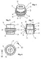
- the oblique slots 34 are formed inclined to the central axis 35 at an angle 36 of about 45 °, as can be seen in particular from Figure 2 of the drawing.
- the separating sleeve 31 has an inwardly projecting flange 30, which is formed so that the thermostat 4 can be inserted from the side with the enlarged opening in the separating sleeve 31 with the ring 7.
- the opening is provided with a reduced diameter portion 310 in the region of the flange 30, so that a radial compression takes place in the inserted position.
- the thermostat 4 with a projection 43 passes through the flange 30, whereby the rubber-elastic ring 7 can be pressed on the one hand by the flange 30 and on the other hand by a front side 40 of the thermostat 4.
- a snap ring 8 can then be inserted into an annular groove 41 of the thermostat 4 for axial securing.
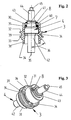
- the double-seat valve slide 3 is thus kept free of play both radially and axially to the thermostat 4, as can be seen in particular from Figure 2 of the drawing.
- the axial fixation of the double valve seat slide 3 to the thermostat 4 is predetermined by the snap ring 8.
- the assembly shown in Figure 2 and 3 can be inserted axially with the cover 21 in the valve cartridge housing 2, wherein a pin 44 sealed out of the water acted upon space of the valve cartridge housing 2 is led out. Then, a return spring 6 is pushed against the downstream end face of the separating sleeve 31 and then the lid 21 is screwed into the valve cartridge housing 2 by means of thread. Thereafter, the so completed valve cartridge can be inserted with the valve cartridge housing 2 in the receiving bore 13 of the housing 1, wherein in the inserted position, the individual inflow channels are sealed by means of O-rings against each other and to the outside. To secure in the inserted position, the eye bolt 14 is screwed into the housing 1.
- a temperature selection device 5 is arranged non-rotatably but axially displaceable in the valve cartridge housing 2.
- a movement thread 50 is formed, with which a not shown in the drawing axially held on the valve cartridge housing 2 rotary handle with an adjusting nut is engaged, so that by a rotary movement of the control handle the Temperaturvor techlvorides 5 axially to the valve cartridge housing 2 is movable.
- the axial movement is transmitted via a plunger 45 to the thermostat 4 and the double-seat valve slide 3, so that in this way the setpoint temperature of the mixed water is adjustable.
Landscapes
- Physics & Mathematics (AREA)
- General Physics & Mathematics (AREA)
- Engineering & Computer Science (AREA)
- Automation & Control Theory (AREA)
- Temperature-Responsive Valves (AREA)
- Valve-Gear Or Valve Arrangements (AREA)
- Multiple-Way Valves (AREA)
Description
- Die Erfindung betrifft ein Mischventil für Kalt- und Heißwasser mit thermostatischer Regelung der Mischwassertemperatur gemäß dem Oberbegriff des Anspruchs1.
- Ein solches Mischventil wurde bereits in JP 2000 337535 offenbart.
- Andere Mischventile sind aus den Druckschriften EP 0 242 680 A2 und DE 102 28 212 A1 bekannt. Bei diesen bekannten Mischventilen ist der Doppelventilsitzschieber mittels Gewinde oder von einer Schraubenfeder gegen einen Anschlag am Thermostaten gedrückt. Diese Anordnung ist kostenaufwendig und wenig geeignet für eine automatisierte Montage des Doppelventilsitzschiebers auf dem Thermostaten.
- Der Erfindung liegt die Aufgabe zugrunde, das im Oberbegriff des Anspruchs 1 angegebenen Mischventil zu verbessern und insbesondere so auszubilden, dass eine kostengünstigere Herstellung und genaue Montage ermöglicht wird.
Diese Aufgabe wird bei einem gattungsgemäßen Mischventil dadurch gelöst, dass zwischen dem Doppelventilsitzschieber und dem Thermostaten über einen gummielastischen Ring eine axial und radial spielfreie Verbindung vorgesehen ist.
Weitere Ausgestaltungen der Erfindung sind in den Ansprüchen 2 bis 11 angegeben. - Mit dem Einsatz des gummielastischen Ringes zusammen mit dem Sprengring kann eine einfach herstellbare und eine sichere automatisierte Montage ermöglichende Steckverbindung zwischen dem Doppelsitzventilschieber und dem Thermostaten gebildet werden. Mit dem gummielastischen Ring können ferner Fertigungstoleranzen kompensiert werden, wobei eine axial als auch radial spielfreie Verbindung zwischen dem Doppelsitzventilschieber und dem Thermostat hergestellt werden kann. Mit Hilfe der flexiblen Halterung über dem gummielastischen Ring können auch in einem gewissen Bereich Schiefstellungen des Doppelventilsitzschiebers zum Thermostaten ermöglicht werden, so dass die Schieberkanten an den zugehörigen Ventilsitzen dicht zur Anlage gelangen können. Die exakte axiale Sicherung des Doppelventilsitzschiebers am Thermostaten erfolgt dabei von dem am Thermostaten gehaltenen Sprengring.
- In einer bevorzugten Ausgestaltung der Erfindung kann der Doppelventilsitzschieber mit einem nach innen vorstehenden Flansch versehen werden, der in der Stecklage radial zwischen dem Sprengring und dem gummielastischen Ring einfasst. Um ein relativ einfaches Verpressen des gummielastischen Ringes zu erreichen, kann vorteilhaft die Stirnseite des Thermostaten konisch ausgebildet sein.
- In einer weiteren bevorzugten Ausgestaltung der Erfindung, bei der im Mischventil zur Erreichung einer besonders hohen Regelgüte hinter den Einströmquerschnitten das Kaltwasser und das Heißwasser von separaten Öffnungen im Doppelventilsitzschieber aufgenommen und beim Durchtritt durch eine am Doppelventilsitzschieber vorgesehene Trennhülse zu temperiertem Mischwasser gemischt und an den Thermostaten abgegeben wird, kann mit dem gummielastischen Ring gleichzeitig eine Abdichtung des Kaltwasserbereiches zum Temperaturfühler des Thermostaten erzielt werden.
Die separaten Öffnungen an den beiden Stirnseiten des Doppelventilsitzschiebers können hierbei zweckmäßig als Schrägschlitze ausgebildet sein, die sich in der Wandung der Trennhülse treffen und einen ringschlitzförmigen Durchtritt des hier gemischten Kalt- und Heißwassers zum stromaufwärts gelegenen Bereich des Temperaturfühlers des Thermostaten abgeben, so dass der Doppelventilsitzschieber kostengünstig einstückig aus Kunststoff hergestellt werden kann.
Die Schrägschlitze können zweckmäßig mit einem Winkel von 20° bis 50° zur Mittelachse geneigt angeordnet werden. Vorteilhaft werden an jeder der beiden Stirnseiten jeweils vier symmetrisch angeordnete ringsegmentförmige Schrägschlitze vorgesehen. - Ein Ausführungsbeispiel der Erfindung ist in der Zeichnung dargestellt und wird im folgenden näher beschrieben. Es zeigt in der Zeichnung
- Figur 1
- ein thermostatgeregeltes Mischventil in schematischer Darstellung im Längsschnitt;
- Figur 2
- die in Figur 1 gezeigte Baugruppe aus dem Thermostaten und dem Doppelventilsitzschieber;
- Figur 3
- die in Figur 2 gezeigte Baugruppe in Perspektivansicht;
- Figur4
- den in Figur 2 gezeigten Doppelventilsitzschieber in Perspektivansicht;
- Figur 5
- den in Figur 4 gezeigten Doppelventilsitzschieber in Seitenansicht;
- Figur 6
- den in Figur 5 gezeigten Doppelventilsitzschieber in Ansicht von oben;
- Figur 7
- den in Figur 6 gezeigten Doppelventilsitzschieber in der Schnittebenen VII.
- Das in Figur 1 gezeigte thermostatgeregelte Mischventil enthält ein Gehäuse 1 mit einem Kaltwassereinlass 10, einem Heißwassereinlass 11 und einem Mischwasserauslass 12. In einer Aufnahmebohrung 13 ist ein Ventilkartuschengehäuse 2 einer Ventilkartusche gedichtet angeordnet. Zur Axialsicherung des Ventilkartuschengehäuses 2 ist in dem Gehäuse 1 mittels Gewinde eine Ringschraube 14 vorgesehen.
- Das Ventilkartuschengehäuse 2 ist am stromabwärtsgelegenen Endbereich mit einem Deckel 21 verschlossen. In der Mantelfläche des Ventilkartuschengehäuses 2 ist ein Einlassquerschnitt 22, der mit dem Kaltwassereinlass 10 in Verbindung steht, und ein Einlassquerschnitt 23, der mit dem Heißwassereinlass 11 in Verbindung steht, vorgesehen. An dem Ventilkartuschengehäuse 2 ist eine Schulter 24 als Kaltwasserventilsitz und an dem Deckel 21 eine Schulter 25 als Heißwasserventilsitz ausgebildet. In dem Freiraum zwischen den beiden Schultern 24, 25 ist ein Doppelventilsitzschieber 3 angeordnet, dessen beide parallel angeordnete Stirnseiten 32, 33 die beiden Einlassquerschnitte 22, 23 bestimmen. Bei einer Axialbewegung des Doppelventilsitzschiebers 3 relativ zum Ventilkartuschengehäuse 2 verändern sich somit die beiden Einlassquerschnitte 22, 23 gegenläufig.
An dem Doppelventilsitzschieber 3 ist jeweils an einer Stirnseite 32, 33 eine Trennhülse 31 mit verringertem Durchmesser angeformt. Mit der Trennhülse 31 wird das je entsprechend den Einlassquerschnitten 22, 23 dosiert zugeführte Kaltwasser und Heißwasser vom Thermostaten 4 abgeschirmt. Zu diesem Zweck ist die Trennhülse einerseits über einen O-Ring 37 zur Innenwandung des Deckels 21 und andererseits mit einem gummielastischen Ring 7 zu dem Thermostaten 4 abgedichtet. Außerdem werden von einem in einer Ringnut 39 des Doppelventilsitzschiebers 3 angeordneten O-Ring, der dichtend in der Innenwandung des Ventilkartuschengehäuses 2 anliegt, der Kaltwasserzuflussraum vom Heißwasserzuflussraum getrennt.
Das zuströmende Kaltwasser kann somit nur durch stromabwärts hinter dem Doppelventilsitzschieber 3 in der Stirnseite 32 angeordnete ringförmige Schrägschlitze 34 und das zuströmende Heißwasser nur durch stromabwärts hinter dem Doppelventilsitzschieber 3 im Bereich der Stirnseite 33 angeordnete ringförmige Schrägschlitze 34 abfließen. Die Schrägschlitze 34 durchdringen dabei die Trennhülse 31 und vereinigen sich kurz vor dem Austritt an der inneren Ringwandung der Trennhülse 31, so dass im Bereich der Trennhülse 31 eine Mischung von Kalt- und Heißwasser zu temperiertem Mischwasser erfolgt, welches dann radial zum stromaufwärts gelegenen Bereich eines Temperaturfühlers 42 des Thermostaten 4 austritt. Die Schrägschlitze 34 sind zur Mittelachse 35 mit einem Winkel 36 von etwa 45° geneigt ausgebildet, wie es insbesondere aus Figur 2 der Zeichnung zu entnehmen ist.
Im Bereich des gummielastischen Rings 7 weist die Trennhülse 31 einen nach innen vorstehenden Flansch 30 auf, der so ausgebildet ist, dass der Thermostat 4 von der Seite mit der erweiterten Öffnung aus in die Trennhülse 31 mit dem Ring 7 eingeschoben werden kann. Für die Aufnahme des Rings 7 in der Trennhülse 31 ist im Bereich des Flansches 30 die Öffnung mit einem im Durchmesser verringerten Teil 310 versehen, so dass eine radiale Verpressung in der Stecklage erfolgt. In der Stecklage durchgreift der Thermostat 4 mit einem Ansatz 43 den Flansch 30, wodurch der gummielastische Ring 7 einerseits von dem Flansch 30 und andererseits von einer Stirnseite 40 des Thermostaten 4 verpresst werden kann. Von der Außenseite her kann dann ein Sprengring 8 in eine Ringnut 41 des Thermostaten 4 zur Axialsicherung eingesetzt werden. Der Doppelsitzventilschieber 3 wird somit sowohl radial als auch axial zum Thermostaten 4 spielfrei gehalten, wie es insbesondere aus Figur 2 der Zeichnung zu entnehmen ist. Die axiale Fixierung des Doppelventilsitzschiebers 3 zum Thermostaten 4 wird dabei vom Sprengring 8 vorgegeben. Da zwischen der Innenwandung der Trennhülse 31 und dem Thermostaten 4 ein Spiel vorgegeben ist, ist ein begrenztes Verschwenken des Doppelventilsitzschiebers 3 zur Mittelachse des Thermostaten 4 möglich, wodurch Fertigungstoleranzen ausgeglichen werden können, so dass beim Aufsetzen des Doppelventilsitzschiebers 3 auf einer Schulter 24 des Kaltwassersitzes oder auf einer Schulter 25 des Heißwassersitzes ein sicherer Abschluss gewährleistet ist. - Die in Figur 2 und 3 dargestellte Baugruppe kann bei entferntem Deckel 21 in das Ventilkartuschengehäuse 2 axial eingeschoben werden, wobei ein Zapfen 44 gedichtet aus dem vom Wasser beaufschlagen Raum des Ventilkartuschengehäuses 2 herausgeführt ist. Sodann wird eine Rückstellfeder 6 gegen die stromabwärts gelegene Stirnseite der Trennhülse 31 geschoben und anschließend der Deckel 21 in das Ventilkartuschengehäuse 2 mittels Gewinde eingeschraubt. Hiernach kann die so komplettierte Ventilkartusche mit dem Ventilkartuschengehäuse 2 in die Aufnahmebohrung 13 des Gehäuses 1 eingeschoben werden, wobei in der Stecklage die einzelnen Zuflusskanäle mit Hilfe von O-Ringen gegeneinander und nach außen abgedichtet sind. Zur Sicherung in der Stecklage wird die Ringschraube 14 in das Gehäuse 1 eingedreht.
Eine Temperaturvorwähleinrichtung 5 ist unverdrehbar aber axial begrenzt verschiebbar in dem Ventilkartuschengehäuse 2 angeordnet. Am äußeren Endbereich der Temperaturvorwählvorrichtung 5 ist ein Bewegungsgewinde 50 ausgebildet, mit dem ein in der Zeichnung nicht dargestellter axial am Ventilkartuschengehäuse 2 gehaltener Drehgriff mit einer Stellmutter in Eingriff steht, so dass durch eine Drehbewegung des Stellgriffes die Temperaturvorwählvorrichtung 5 axial zum Ventilkartuschengehäuse 2 bewegbar ist. Die Axialbewegung wird über einen Stößel 45 auf den Thermostaten 4 und den Doppelsitzventilschieber 3 übertragen, so dass hierdurch die Sollwerttemperatur des Mischwassers einstellbar ist.
Bei einer Mischwasserentnahme aus dem Mischwasserauslass 12 strömen somit durch die Einlassquerschnitte 22, 23 entsprechende Mengen von Kalt- und Heißwasser, so dass die voreingestellte Mischwassertemperatur am Austrittsbereich der Schrägschlitze 34 sich einstellt. Weicht die Isttemperatur von der Sollwerttemperatur ab, so wird diese Temperaturänderung von dem Temperaturfühler 42 des Thermostaten 4 erfasst und entsprechend eine axiale Auslenkung des Stößels 45 erzeugt, so dass sich die Isttemperatur dem Sollwert der Mischwassertemperatur wieder annähert.
Claims (11)
- Mischventil für Kalt- und Heißwasser mit thermostatischer Regelung der Mischwassertemperatur- durch einen von einer Temperaturvorwählvorrichtung (5) positionierten,- mit einem Doppelventilsitzschieber (3) verbundenen Thermostaten (4),- - der in einem Gehäuse (1,2)- - - mit wenigstens je einem Kalt- und Heißwassereinlass (10,11)
sowie- - - - wenigstens einem Mischwasserauslass (12) angeordnet ist,- wobei Einlassquerschnitte (22,23) an beiden Einströmspalten des Mischventils vom Doppelventilsitzschieber (3) mit seinen beiden Stirnseiten (32,33) gegensinnig gesteuert sind, unddadurch gekennzeichnet, dass- - der Doppelventilsitzschieber (3) auf dem Thermostaten (4) aufgebracht,- - axial an einer Stirnseite (40) anliegt und- - über einen Sprengring (8) mit dem Thermostaten (4) verbunden ist,
zwischen dem Doppelventilsitzschieber (3) und dem Thermostaten (4) über einen gummielastischen Ring (7) eine axial und radial spielfreie Verbindung vorgesehen ist. - Mischventil nach Anspruch 1, dadurch gekennzeichnet, dass zwischen dem Sprengring (8) und dem gummielastischem Ring (7) am Doppelventilsitzschieber (3) an einem rohrförmigen Bereich ein nach innen vorstehender Flansch (30) angeformt ist.
- Mischventil nach Anspruch 1 oder 2, dadurch gekennzeichnet, dass die am Thermostaten (4) ausgebildete Stirnseite (40) für die Anlage des gummielastischen Ringes (7) konisch ausgebildet ist.
- Mischventil nach wenigstens einem der vorhergehenden Ansprüche, dadurch gekennzeichnet, dass der Sprengring (8) von einer im Thermostat (4) ausgebildeten Ringnut (41) aufgenommen ist.
- Mischventil nach wenigstens einem der vorhergehenden Ansprüche, wobei außerdem stromabwärts hinter den Einströmquerschnitten das Kaltwasser und das Heißwasser von separaten Öffnungen im Doppelventilsitzschieber (3) aufgenommen und beim Durchtritt durch eine am Doppelventilsitzschieber (3) vorgesehene Trennhülse (31) zu temperiertem Wasser gemischt und gerichtet auf den Thermostaten (4) abgegeben ist, dadurch gekennzeichnet, dass der gummielastische Ring (7) den von der Trennhülse (31) begrenzten Kaltwasserbereich zum Temperaturfühler (42) des Thermostaten (5) abdichtet.
- Mischventil nach Anspruch 5, dadurch gekennzeichnet, dass für die Aufnahme des Rings (7) in der Trennhülse (31) im Bereich des Flansches (30) die Öffnung in der Trennhülse (31) mit einem im Durchmesser verringerten Teil (310) versehen ist.
- Mischventil nach Anspruch 5 oder 6, dadurch gekennzeichnet, dass die Öffnungen an den beiden Stirnseiten (32, 33) des Doppelventilsitzschiebers (3) stromabwärts hinter den Einlassquerschnitten (22, 23) als ringförmige Schrägschlitze (34) ausgebildet sind, die sich in der Wandung der Trennhülse (31) treffen und den Durchtritt zum stromaufwärts gelegenen Bereich des Temperaturfühlers (42) freigeben.
- Mischventil nach Anspruch 7, dadurch gekennzeichnet, dass an beiden Stirnseiten (32, 33) jeweils symmetrisch angeordnete Schrägschlitze (34) ausgebildet sind.
- Mischventil nach Anspruch 7 oder 8, dadurch gekennzeichnet, dass die Schrägschlitze (34) zur Mittelachse (35) um einen Winkel (36) von 20° bis 50° geneigt angeordnet sind.
- Mischventil nach wenigstens einem der Ansprüche 7 bis 9, dadurch gekennzeichnet, dass jeweils vier Schrägschlitze (34) an einer Stirnseite (32, 33) ausgebildet sind.
- Mischventil nach wenigstens einem der vorhergehenden Ansprüche, dadurch gekennzeichnet, dass der Doppelventilsitzschieber (3) einstückig aus Kunststoff hergestellt ist.
Applications Claiming Priority (1)
| Application Number | Priority Date | Filing Date | Title |
|---|---|---|---|
| DE102004042961A DE102004042961A1 (de) | 2004-09-02 | 2004-09-02 | Mischventil |
Publications (2)
| Publication Number | Publication Date |
|---|---|
| EP1632702A1 EP1632702A1 (de) | 2006-03-08 |
| EP1632702B1 true EP1632702B1 (de) | 2007-04-18 |
Family
ID=35064825
Family Applications (1)
| Application Number | Title | Priority Date | Filing Date |
|---|---|---|---|
| EP05018228A Expired - Lifetime EP1632702B1 (de) | 2004-09-02 | 2005-08-23 | Mischventil |
Country Status (5)
| Country | Link |
|---|---|
| EP (1) | EP1632702B1 (de) |
| AT (1) | ATE360168T1 (de) |
| DE (2) | DE102004042961A1 (de) |
| DK (1) | DK1632702T3 (de) |
| ES (1) | ES2286747T3 (de) |
Families Citing this family (1)
| Publication number | Priority date | Publication date | Assignee | Title |
|---|---|---|---|---|
| FR3078787B1 (fr) * | 2018-03-07 | 2021-01-22 | Delabie | Robinet mitigeur thermostatique |
Family Cites Families (4)
| Publication number | Priority date | Publication date | Assignee | Title |
|---|---|---|---|---|
| DE1206240B (de) * | 1964-05-09 | 1965-12-02 | Kosmos Armaturen Und Appbau Fr | Thermostatisch betaetigtes Ventil, z. B. fuer Klimatruhen |
| JPS60256512A (ja) * | 1984-06-01 | 1985-12-18 | Sanshin Ind Co Ltd | 直冷式水冷エンジンのサ−モスタツト |
| JP4068761B2 (ja) * | 1999-05-26 | 2008-03-26 | 日本サーモスタット株式会社 | 湯水自動混合弁 |
| DE10228212A1 (de) * | 2002-06-24 | 2004-01-22 | Grohe Water Technology Ag & Co. Kg | Mischventil |
-
2004
- 2004-09-02 DE DE102004042961A patent/DE102004042961A1/de not_active Withdrawn
-
2005
- 2005-08-23 DE DE502005000601T patent/DE502005000601D1/de not_active Expired - Lifetime
- 2005-08-23 ES ES05018228T patent/ES2286747T3/es not_active Expired - Lifetime
- 2005-08-23 EP EP05018228A patent/EP1632702B1/de not_active Expired - Lifetime
- 2005-08-23 AT AT05018228T patent/ATE360168T1/de not_active IP Right Cessation
- 2005-08-23 DK DK05018228T patent/DK1632702T3/da active
Non-Patent Citations (1)
| Title |
|---|
| None * |
Also Published As
| Publication number | Publication date |
|---|---|
| DE102004042961A1 (de) | 2006-03-09 |
| ATE360168T1 (de) | 2007-05-15 |
| EP1632702A1 (de) | 2006-03-08 |
| DE502005000601D1 (de) | 2007-05-31 |
| DK1632702T3 (da) | 2007-08-06 |
| ES2286747T3 (es) | 2007-12-01 |
Similar Documents
| Publication | Publication Date | Title |
|---|---|---|
| DE60209666T2 (de) | Vierteldrehungsthermostatischekartusche mit konzentrischem Antrieb, mit keramischen Scheiben, und eine Mischbatterie die diese enthält | |
| EP3420430B1 (de) | Thermostat-mischventil | |
| EP0242675A2 (de) | Mischbatterie | |
| DE69623637T2 (de) | Eine kugelventilkartusche für ein mischventil | |
| EP2634464B1 (de) | Einhandhebelmischerkartusche | |
| EP2634463B1 (de) | Einhandhebelmischerkartusche | |
| EP2710940B1 (de) | Mehrwegeventil | |
| EP2771600B1 (de) | Einhandhebelmischerkartusche | |
| EP0884539A1 (de) | Anschlussarmatur zum Anschliessen eines Druckausdehnungs-Gefässes für erwärmtes Trinkwasser | |
| DE4423240C1 (de) | Thermostatventil | |
| DE3518698C2 (de) | Mischventil | |
| DE112016005186B4 (de) | Thermostatkartusche zum Regeln von zu mischenden warmen und kalten Fluiden | |
| EP1632702B1 (de) | Mischventil | |
| DE102004049253B4 (de) | Thermostatventil | |
| DE3941106C2 (de) | Sanitäre Mischbatterie für den Wandanschluß | |
| DE4123048C2 (de) | Thermostatgeregeltes Mischventil | |
| DE19813296A1 (de) | Mischbatterie | |
| DE2716831A1 (de) | Mischventil | |
| DE10305394A1 (de) | Flüssigkeitsventil für Heiz- und/oder Kühlanlagen | |
| EP3931474B1 (de) | Armatur mit ausziehbarem schlauch | |
| EP2461223B1 (de) | Thermostatventil | |
| EP0905454A2 (de) | Anschlussarmatur zum Anschliessen eines Druckausdehnungs-Gefässes an ein Leitungssystem | |
| EP1367306A1 (de) | Ventileinsatz | |
| CH691134A5 (de) | Steuerpatrone für eine Mischarmatur. | |
| EP3112540A1 (de) | Ventiloberteil |
Legal Events
| Date | Code | Title | Description |
|---|---|---|---|
| PUAI | Public reference made under article 153(3) epc to a published international application that has entered the european phase |
Free format text: ORIGINAL CODE: 0009012 |
|
| AK | Designated contracting states |
Kind code of ref document: A1 Designated state(s): AT BE BG CH CY CZ DE DK EE ES FI FR GB GR HU IE IS IT LI LT LU LV MC NL PL PT RO SE SI SK TR |
|
| AX | Request for extension of the european patent |
Extension state: AL BA HR MK YU |
|
| RAP1 | Party data changed (applicant data changed or rights of an application transferred) |
Owner name: GROHE AG |
|
| 17P | Request for examination filed |
Effective date: 20060508 |
|
| AKX | Designation fees paid |
Designated state(s): AT BE BG CH CY CZ DE DK EE ES FI FR GB GR HU IE IS IT LI LT LU LV MC NL PL PT RO SE SI SK TR |
|
| GRAP | Despatch of communication of intention to grant a patent |
Free format text: ORIGINAL CODE: EPIDOSNIGR1 |
|
| GRAS | Grant fee paid |
Free format text: ORIGINAL CODE: EPIDOSNIGR3 |
|
| GRAA | (expected) grant |
Free format text: ORIGINAL CODE: 0009210 |
|
| AK | Designated contracting states |
Kind code of ref document: B1 Designated state(s): AT BE BG CH CY CZ DE DK EE ES FI FR GB GR HU IE IS IT LI LT LU LV MC NL PL PT RO SE SI SK TR |
|
| PG25 | Lapsed in a contracting state [announced via postgrant information from national office to epo] |
Ref country code: SI Free format text: LAPSE BECAUSE OF FAILURE TO SUBMIT A TRANSLATION OF THE DESCRIPTION OR TO PAY THE FEE WITHIN THE PRESCRIBED TIME-LIMIT Effective date: 20070418 |
|
| REG | Reference to a national code |
Ref country code: CH Ref legal event code: EP |
|
| REG | Reference to a national code |
Ref country code: IE Ref legal event code: FG4D Free format text: LANGUAGE OF EP DOCUMENT: GERMAN |
|
| REF | Corresponds to: |
Ref document number: 502005000601 Country of ref document: DE Date of ref document: 20070531 Kind code of ref document: P |
|
| REG | Reference to a national code |
Ref country code: SE Ref legal event code: TRGR |
|
| REG | Reference to a national code |
Ref country code: DK Ref legal event code: T3 |
|
| PG25 | Lapsed in a contracting state [announced via postgrant information from national office to epo] |
Ref country code: IS Free format text: LAPSE BECAUSE OF FAILURE TO SUBMIT A TRANSLATION OF THE DESCRIPTION OR TO PAY THE FEE WITHIN THE PRESCRIBED TIME-LIMIT Effective date: 20070818 |
|
| GBT | Gb: translation of ep patent filed (gb section 77(6)(a)/1977) |
Effective date: 20070806 |
|
| PG25 | Lapsed in a contracting state [announced via postgrant information from national office to epo] |
Ref country code: PT Free format text: LAPSE BECAUSE OF FAILURE TO SUBMIT A TRANSLATION OF THE DESCRIPTION OR TO PAY THE FEE WITHIN THE PRESCRIBED TIME-LIMIT Effective date: 20070918 |
|
| ET | Fr: translation filed | ||
| PG25 | Lapsed in a contracting state [announced via postgrant information from national office to epo] |
Ref country code: PL Free format text: LAPSE BECAUSE OF FAILURE TO SUBMIT A TRANSLATION OF THE DESCRIPTION OR TO PAY THE FEE WITHIN THE PRESCRIBED TIME-LIMIT Effective date: 20070418 |
|
| REG | Reference to a national code |
Ref country code: IE Ref legal event code: FD4D |
|
| REG | Reference to a national code |
Ref country code: ES Ref legal event code: FG2A Ref document number: 2286747 Country of ref document: ES Kind code of ref document: T3 |
|
| PG25 | Lapsed in a contracting state [announced via postgrant information from national office to epo] |
Ref country code: IE Free format text: LAPSE BECAUSE OF FAILURE TO SUBMIT A TRANSLATION OF THE DESCRIPTION OR TO PAY THE FEE WITHIN THE PRESCRIBED TIME-LIMIT Effective date: 20070418 Ref country code: CZ Free format text: LAPSE BECAUSE OF FAILURE TO SUBMIT A TRANSLATION OF THE DESCRIPTION OR TO PAY THE FEE WITHIN THE PRESCRIBED TIME-LIMIT Effective date: 20070418 Ref country code: BG Free format text: LAPSE BECAUSE OF FAILURE TO SUBMIT A TRANSLATION OF THE DESCRIPTION OR TO PAY THE FEE WITHIN THE PRESCRIBED TIME-LIMIT Effective date: 20070718 |
|
| PLBE | No opposition filed within time limit |
Free format text: ORIGINAL CODE: 0009261 |
|
| STAA | Information on the status of an ep patent application or granted ep patent |
Free format text: STATUS: NO OPPOSITION FILED WITHIN TIME LIMIT |
|
| PG25 | Lapsed in a contracting state [announced via postgrant information from national office to epo] |
Ref country code: SK Free format text: LAPSE BECAUSE OF FAILURE TO SUBMIT A TRANSLATION OF THE DESCRIPTION OR TO PAY THE FEE WITHIN THE PRESCRIBED TIME-LIMIT Effective date: 20070418 Ref country code: LT Free format text: LAPSE BECAUSE OF FAILURE TO SUBMIT A TRANSLATION OF THE DESCRIPTION OR TO PAY THE FEE WITHIN THE PRESCRIBED TIME-LIMIT Effective date: 20070418 Ref country code: LV Free format text: LAPSE BECAUSE OF FAILURE TO SUBMIT A TRANSLATION OF THE DESCRIPTION OR TO PAY THE FEE WITHIN THE PRESCRIBED TIME-LIMIT Effective date: 20070418 |
|
| 26N | No opposition filed |
Effective date: 20080121 |
|
| PG25 | Lapsed in a contracting state [announced via postgrant information from national office to epo] |
Ref country code: MC Free format text: LAPSE BECAUSE OF NON-PAYMENT OF DUE FEES Effective date: 20070831 Ref country code: GR Free format text: LAPSE BECAUSE OF FAILURE TO SUBMIT A TRANSLATION OF THE DESCRIPTION OR TO PAY THE FEE WITHIN THE PRESCRIBED TIME-LIMIT Effective date: 20070719 |
|
| PG25 | Lapsed in a contracting state [announced via postgrant information from national office to epo] |
Ref country code: RO Free format text: LAPSE BECAUSE OF FAILURE TO SUBMIT A TRANSLATION OF THE DESCRIPTION OR TO PAY THE FEE WITHIN THE PRESCRIBED TIME-LIMIT Effective date: 20070418 |
|
| PGFP | Annual fee paid to national office [announced via postgrant information from national office to epo] |
Ref country code: DK Payment date: 20080814 Year of fee payment: 4 |
|
| PGFP | Annual fee paid to national office [announced via postgrant information from national office to epo] |
Ref country code: AT Payment date: 20080814 Year of fee payment: 4 |
|
| PG25 | Lapsed in a contracting state [announced via postgrant information from national office to epo] |
Ref country code: EE Free format text: LAPSE BECAUSE OF FAILURE TO SUBMIT A TRANSLATION OF THE DESCRIPTION OR TO PAY THE FEE WITHIN THE PRESCRIBED TIME-LIMIT Effective date: 20070418 |
|
| PGFP | Annual fee paid to national office [announced via postgrant information from national office to epo] |
Ref country code: SE Payment date: 20080815 Year of fee payment: 4 Ref country code: BE Payment date: 20080918 Year of fee payment: 4 |
|
| PG25 | Lapsed in a contracting state [announced via postgrant information from national office to epo] |
Ref country code: CY Free format text: LAPSE BECAUSE OF FAILURE TO SUBMIT A TRANSLATION OF THE DESCRIPTION OR TO PAY THE FEE WITHIN THE PRESCRIBED TIME-LIMIT Effective date: 20070418 |
|
| PG25 | Lapsed in a contracting state [announced via postgrant information from national office to epo] |
Ref country code: LU Free format text: LAPSE BECAUSE OF NON-PAYMENT OF DUE FEES Effective date: 20070823 |
|
| PG25 | Lapsed in a contracting state [announced via postgrant information from national office to epo] |
Ref country code: HU Free format text: LAPSE BECAUSE OF FAILURE TO SUBMIT A TRANSLATION OF THE DESCRIPTION OR TO PAY THE FEE WITHIN THE PRESCRIBED TIME-LIMIT Effective date: 20071019 Ref country code: TR Free format text: LAPSE BECAUSE OF FAILURE TO SUBMIT A TRANSLATION OF THE DESCRIPTION OR TO PAY THE FEE WITHIN THE PRESCRIBED TIME-LIMIT Effective date: 20070418 |
|
| PGFP | Annual fee paid to national office [announced via postgrant information from national office to epo] |
Ref country code: FI Payment date: 20090814 Year of fee payment: 5 |
|
| BERE | Be: lapsed |
Owner name: GROHE A.G. Effective date: 20090831 |
|
| REG | Reference to a national code |
Ref country code: CH Ref legal event code: PL |
|
| REG | Reference to a national code |
Ref country code: DK Ref legal event code: EBP |
|
| PG25 | Lapsed in a contracting state [announced via postgrant information from national office to epo] |
Ref country code: LI Free format text: LAPSE BECAUSE OF NON-PAYMENT OF DUE FEES Effective date: 20090831 Ref country code: CH Free format text: LAPSE BECAUSE OF NON-PAYMENT OF DUE FEES Effective date: 20090831 |
|
| PG25 | Lapsed in a contracting state [announced via postgrant information from national office to epo] |
Ref country code: BE Free format text: LAPSE BECAUSE OF NON-PAYMENT OF DUE FEES Effective date: 20090831 Ref country code: AT Free format text: LAPSE BECAUSE OF NON-PAYMENT OF DUE FEES Effective date: 20090823 |
|
| PG25 | Lapsed in a contracting state [announced via postgrant information from national office to epo] |
Ref country code: DK Free format text: LAPSE BECAUSE OF NON-PAYMENT OF DUE FEES Effective date: 20090831 |
|
| PG25 | Lapsed in a contracting state [announced via postgrant information from national office to epo] |
Ref country code: FI Free format text: LAPSE BECAUSE OF NON-PAYMENT OF DUE FEES Effective date: 20100823 Ref country code: SE Free format text: LAPSE BECAUSE OF NON-PAYMENT OF DUE FEES Effective date: 20090824 |
|
| REG | Reference to a national code |
Ref country code: FR Ref legal event code: PLFP Year of fee payment: 12 |
|
| REG | Reference to a national code |
Ref country code: FR Ref legal event code: PLFP Year of fee payment: 13 |
|
| REG | Reference to a national code |
Ref country code: FR Ref legal event code: PLFP Year of fee payment: 14 |
|
| PGFP | Annual fee paid to national office [announced via postgrant information from national office to epo] |
Ref country code: IT Payment date: 20200826 Year of fee payment: 16 |
|
| PGFP | Annual fee paid to national office [announced via postgrant information from national office to epo] |
Ref country code: ES Payment date: 20201023 Year of fee payment: 16 |
|
| PG25 | Lapsed in a contracting state [announced via postgrant information from national office to epo] |
Ref country code: IT Free format text: LAPSE BECAUSE OF NON-PAYMENT OF DUE FEES Effective date: 20210823 |
|
| REG | Reference to a national code |
Ref country code: ES Ref legal event code: FD2A Effective date: 20220930 |
|
| PG25 | Lapsed in a contracting state [announced via postgrant information from national office to epo] |
Ref country code: ES Free format text: LAPSE BECAUSE OF NON-PAYMENT OF DUE FEES Effective date: 20210824 |
|
| PGFP | Annual fee paid to national office [announced via postgrant information from national office to epo] |
Ref country code: GB Payment date: 20220822 Year of fee payment: 18 |
|
| P01 | Opt-out of the competence of the unified patent court (upc) registered |
Effective date: 20230526 |
|
| PGFP | Annual fee paid to national office [announced via postgrant information from national office to epo] |
Ref country code: NL Payment date: 20230821 Year of fee payment: 19 |
|
| PGFP | Annual fee paid to national office [announced via postgrant information from national office to epo] |
Ref country code: FR Payment date: 20230822 Year of fee payment: 19 Ref country code: DE Payment date: 20230821 Year of fee payment: 19 |
|
| GBPC | Gb: european patent ceased through non-payment of renewal fee |
Effective date: 20230823 |
|
| PG25 | Lapsed in a contracting state [announced via postgrant information from national office to epo] |
Ref country code: GB Free format text: LAPSE BECAUSE OF NON-PAYMENT OF DUE FEES Effective date: 20230823 |
|
| PG25 | Lapsed in a contracting state [announced via postgrant information from national office to epo] |
Ref country code: GB Free format text: LAPSE BECAUSE OF NON-PAYMENT OF DUE FEES Effective date: 20230823 |
|
| REG | Reference to a national code |
Ref country code: DE Ref legal event code: R119 Ref document number: 502005000601 Country of ref document: DE |
|
| REG | Reference to a national code |
Ref country code: NL Ref legal event code: MM Effective date: 20240901 |
|
| PG25 | Lapsed in a contracting state [announced via postgrant information from national office to epo] |
Ref country code: NL Free format text: LAPSE BECAUSE OF NON-PAYMENT OF DUE FEES Effective date: 20240901 |
|
| PG25 | Lapsed in a contracting state [announced via postgrant information from national office to epo] |
Ref country code: DE Free format text: LAPSE BECAUSE OF NON-PAYMENT OF DUE FEES Effective date: 20250301 |
|
| PG25 | Lapsed in a contracting state [announced via postgrant information from national office to epo] |
Ref country code: FR Free format text: LAPSE BECAUSE OF NON-PAYMENT OF DUE FEES Effective date: 20240831 |