EP1367306A1 - Cartouche de soupape - Google Patents
Cartouche de soupape Download PDFInfo
- Publication number
- EP1367306A1 EP1367306A1 EP02012055A EP02012055A EP1367306A1 EP 1367306 A1 EP1367306 A1 EP 1367306A1 EP 02012055 A EP02012055 A EP 02012055A EP 02012055 A EP02012055 A EP 02012055A EP 1367306 A1 EP1367306 A1 EP 1367306A1
- Authority
- EP
- European Patent Office
- Prior art keywords
- valve insert
- sealing
- insert according
- base body
- rod
- Prior art date
- Legal status (The legal status is an assumption and is not a legal conclusion. Google has not performed a legal analysis and makes no representation as to the accuracy of the status listed.)
- Withdrawn
Links
Images

Classifications
-
- F—MECHANICAL ENGINEERING; LIGHTING; HEATING; WEAPONS; BLASTING
- F16—ENGINEERING ELEMENTS AND UNITS; GENERAL MEASURES FOR PRODUCING AND MAINTAINING EFFECTIVE FUNCTIONING OF MACHINES OR INSTALLATIONS; THERMAL INSULATION IN GENERAL
- F16K—VALVES; TAPS; COCKS; ACTUATING-FLOATS; DEVICES FOR VENTING OR AERATING
- F16K27/00—Construction of housing; Use of materials therefor
- F16K27/02—Construction of housing; Use of materials therefor of lift valves
- F16K27/0263—Construction of housing; Use of materials therefor of lift valves multiple way valves
-
- F—MECHANICAL ENGINEERING; LIGHTING; HEATING; WEAPONS; BLASTING
- F16—ENGINEERING ELEMENTS AND UNITS; GENERAL MEASURES FOR PRODUCING AND MAINTAINING EFFECTIVE FUNCTIONING OF MACHINES OR INSTALLATIONS; THERMAL INSULATION IN GENERAL
- F16K—VALVES; TAPS; COCKS; ACTUATING-FLOATS; DEVICES FOR VENTING OR AERATING
- F16K11/00—Multiple-way valves, e.g. mixing valves; Pipe fittings incorporating such valves
- F16K11/02—Multiple-way valves, e.g. mixing valves; Pipe fittings incorporating such valves with all movable sealing faces moving as one unit
- F16K11/04—Multiple-way valves, e.g. mixing valves; Pipe fittings incorporating such valves with all movable sealing faces moving as one unit comprising only lift valves
- F16K11/048—Multiple-way valves, e.g. mixing valves; Pipe fittings incorporating such valves with all movable sealing faces moving as one unit comprising only lift valves with valve seats positioned between movable valve members
Definitions
- the invention relates to a valve insert for a compact heating system according to the features specified in the preamble of claim 1.
- Compact heating systems of the type mentioned are for example known from EP 0 797 057 B1. With these plants, a variety of system components in a very small space. For this are usually one or more structurally complex Injection molded parts are provided to which the piping, the heat exchanger, the pump and other components can be connected immediately. These systems are typically used to supply space heating on the one hand and for the production of hot water on the other hand. The heat supplied to the fluid in a primary heat exchanger Depending on the operating mode, the room heating, d. H. the radiators or a secondary heat exchanger, which too withdrawing hot water heated, supplied.
- EP 0 797 057 B1 does not specifically describe how the valve insert is used is designed constructively, but currently have essentially two types established on the market.
- the valve insert is installed in the system from two sides, which is expensive and also a closure body on one side conditional, in the other the valve insert is in from one side inserted the system.
- Such valve inserts are, for example known from EP 0 679 821 B1 or DE 201 03 992 U 1.
- valve inserts have generally proven themselves because they are in they can usually be integrated into the system from the front have the disadvantage, however, that the system has very high manufacturing accuracies be required to ensure functionality.
- the system has very high manufacturing accuracies be required to ensure functionality.
- Dirt particles entering the sealing seat when closing the corresponding part of the system can be replaced with what is extremely costly and labor intensive.
- the invention is based on the object Generic valve insert in such a way that the aforementioned Disadvantages are avoided or at least reduced and that the plant side simplifies production.
- the basic idea of the present invention is not only the or the sealing body, but to integrate both sealing seats in the valve insert.
- the manufacturing accuracy of the heating system, in particular the receptacle for the valve insert is considerably less Requirements than were previously required. Because it has to neither the valve insert in its length and arrangement exactly to the system side Recording must be coordinated or vice versa still needs to be provided on the system side a sealing seat, which is also high Manufacturing accuracy required.
- These precise and coordinated Components are all in the valve insert according to the invention provided so that even in the event of a leak, a defect or any other failure, only the valve insert has to be replaced and no components of the compact heating system. In particular if a sealing seat is damaged, it can be replaced by replacing the Valve insert are fixed.
- the sealing seats are advantageously both arranged in the base body because then, for example, when repairing the valve insert, only this basic body must be replaced if one or both sealing seats should be renewed.
- the actuator is preferably displaceable in the base body supported rod formed on which the sealing body (or the common body that unites both sealing bodies) in a given Distance to each other are attached. Then if this rod, as provided according to the invention, positively with a drive unit is connected, the valve position can be independent of pressure can be controlled without the risk of water hammer or Influences of flow exist.
- the distance between the sealing body can be easily by a spacer arranged on the rod between the sealing bodies be determined, so that also lower requirements manufacturing accuracy.
- the sealing bodies themselves are preferably made of elastomeric washers, for example made of rubber or an elastomeric plastic, they can be between the spacer on the one hand and support washers on the other hand, between a shoulder of the rod and a fastening element be clamped.
- the Base body on a coupling body which is also part of the valve insert and in which the rod seals to the outside to form a mechanical Drive is guided and is coupled to this.
- the basic body then forms the part of the insert in which the sealing seats are provided are, whereas the coupling body for setting the insert is provided in the system and also for connecting the Drive unit.
- a sealing ring in particular an O-ring, which seals the insert against the receptacle between Base body and coupling body is arranged, for example by a groove formed between them.
- a sealing ring in particular an O-ring, which seals the insert against the receptacle between Base body and coupling body is arranged, for example by a groove formed between them.
- One formed from two components Groove has compared to a circumferential groove in an injection molded component the advantage that it is free of burrs and thus a better sealing effect guaranteed.
- the tool can be essential for the components can be designed more easily, because one-way demolding is possible.
- the coupling body advantageously has a link guide into which the mechanical drive, in particular in the form of a drive unit is preferably inserted transversely.
- the mechanical drive in particular in the form of a drive unit is preferably inserted transversely.
- By pushing in transversely can not just lock in the direction of actuation without further constructive measures take place, but it can be done simultaneously the defined positioning also a coupling with the actuator take place, also positively.
- the actuator has a recess on one side, which at the end when inserting the drive unit overlaps the actuating rod and thus positively in the axial direction the rod couples to the actuator of the drive unit.
- the drive unit can therefore operate the operating rod in both directions press, it is therefore not necessary to reset the spring, which has the known and the disadvantages described above.
- the drive unit preferably has a stepper motor with a downstream one Spindle drive on, so that an exclusively electrical control sufficient to fit the sealing body in relation to sealing seats to move the defined position.
- the valve insert according to the invention is preferably in the direction of insertion graduated or tapered so that it has no major frictional resistance and without the circumferential seals, in particular Damage O-rings in their surface, in the system side Recording can be inserted.
- the O-rings are therefore constructive, which seal the insert against the intake - this are typically three in the training according to the invention dimensioned that seen from the inside out, the diameter enlarged, the same applies to the grooves or the receiving side Sealing surfaces.
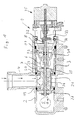
- Fig. 1 is a valve insert 1 in the installed position in a structural unit 2 of a compact heating system shown.
- the assembly 2 has a receptacle 3 for the valve insert 1.
- Open within the intake 3 an inlet port 4 and two outlet-side channels 5 and 6, which by means of the valve.
- the flow direction is typical according to the arrow from the inlet port 4 to output side channel 5 and / or channel 6.
- the valve insert 1 has a base body 7 and an adjoining one Coupling body 8, which has a bayonet connection 9, 10 positively connected to each other with the incorporation of an O-ring 11 are.
- the base body 7 is a structure of essentially hollow cylindrical shape with in the direction of the recording 3 is formed smaller and smaller outside diameter it together with the clutch body 8 with as little friction as possible in the To be able to insert recording 3.
- the base body 7 points to his to the coupling body 8 facing end with a bayonet ring 9 two inward-facing projections 12, which in a coupling body side provided bayonet receptacle 10 insertable and can be locked by turning them.
- the base body 7 has two sealing seats 13 and 14, in the area of these Sealing seats, the base body 7 is annular, in between connected by longitudinal webs 15 or by webs 16 with the bayonet ring 9.
- the Base body 7 has a groove 17 and a groove 18 on its outer circumference larger diameter to that for incorporating an O-ring 19 or an O-ring 20 are provided.
- the O-ring 19 has a smaller one Diameter than the O-ring 20 and the O-ring 20 is smaller Diameter than the O-ring 11.
- the inner wall of the holder 3 is dimensioned accordingly in these areas, so that after Insert the valve insert 1 into the receptacle 3 with a seal these areas between base body 7 and coupling body 8 and the recording 3 results.
- An actuating rod is located within the base body 7 and the coupling body 8 21 slidably mounted in the direction of its longitudinal axis.
- the actuating rod 21 is guided within the coupling body 8, sealed by means of two O-rings 22 and against this.
- the above components are on the operating rod slipped on and are pushed through the final clamping washer 29, whose inner diameter is smaller than the outer diameter of the cylindrical end portion of the actuating rod 21 is non-positive held by the five sheet metal sections formed on the inner circumference 30 are clamped on the operating rod 21 and on this way hold the aforementioned components.
- the sealing body 25 is the sealing seat 13 and the sealing body 27 Seal seat 14 assigned.
- the spacer 26 is dimensioned such that in the intermediate position shown in Fig. 1, the inlet 4 with the channels 5 and 6 is wired, but only with half each Cross-section. The full cross section of the sewer connection is only in the respective end positions reached, d. H. the line connection between the inlet 4 and the channel 5 is fully open when the Sealing body 25 sits on the sealing seat 13 or vice versa when the Sealing body 27 sits on the sealing seat 14, the line connection between Inlet 4 and channel 6 completely made.
- the O-rings 19 and 20 are in the direction of insertion the valve insert 1 seen behind or in front of the inlet 4 arranged, so seal it in the area between the base body 7 and recording 3 opposite channels 5 and 6 respectively.
- the seal outwards via the O-ring 11, the seat of which is on the valve insert side 1 is formed by a shoulder in the coupling body.
- the coupling body 8 seals the valve insert via its wall 31 1 outwards, d. H. compared to the recording 3, and on the circumference in connection with the O-ring 11 and in the area of the bushing the operating rod 21 by means of the O-rings 22.
- the actuating rod 21 faces away from the base body 7 End on an end projection 32, the circumference protrudes from the slender end portion of the operating rod 21.
- This projection 32 is used for positive coupling with an actuator 33 of a drive unit 35, which in turn has a positive fit in a link guide 34 at the end of the coupling body 8 by transverse insertion is incorporated.
- the drive unit can 35 from above, d. H. transverse to the direction of displacement of the actuating rod 21 are inserted into the link guide 34, wherein at the same time the free end of the actuator 33 the projection 32 at the end of the Actuating rod 21 engages in such a way that in the directions of travel the actuating rod 21 is positive.
- the drive unit 35 consists of a not shown here in detail Stepper motor, which is also not shown in detail Spindle drive is connected in such a way that according to the Direction of rotation and the angle of rotation of the stepper motor of the actuator 33 predetermined dimension in a predetermined direction in the axial direction the actuating rod 21 moves and thus the position of the sealing body 25 and 27 controls in relation to the associated seal sets 13 and 14.
- valve insert 1 formed in this way can be connected to it Drive unit 35 inserted into the receptacle 3 and by means of a bracket 36 can be locked in this.
- the valve insert 1 is then sealed against the receptacle 3 in the intended manner and location-oriented. It can be seen that in this respect the recording side the tolerances can be relatively large without the function of To influence valve insert.
- the control takes place exclusively by appropriate control of the stepper motor.
- the drive unit can be installed as well as with the valve insert removed be replaced. In the event that a sealing seat is damaged or is worn out, only the base body 7 needs to be replaced or to be reworked.
- the sealing body 25 and 27 can also comparatively easy to replace after the valve insert 1 is removed from the receptacle 3.
- the 3/2-way valve shown can both behind the primary heat exchanger and in front of the primary heat exchanger to be ordered.
- it is, as can be seen from the flow direction indicated by arrows in FIG. 1 is located behind the primary heat exchanger, which also has the particular advantage that both sealing bodies 25 and 27 when closing the respective channel 5 or 6 against the flow direction be moved, which means that the Risk of water hammer is excluded. Beyond that even with a different arrangement, this risk is at least reduced because the sealing body 25 and 27 always on the operating rod 21 and the drive is positively coupled to it in both directions of travel is guided with almost no play.
Landscapes
- Engineering & Computer Science (AREA)
- General Engineering & Computer Science (AREA)
- Mechanical Engineering (AREA)
- Multiple-Way Valves (AREA)
Priority Applications (2)
| Application Number | Priority Date | Filing Date | Title |
|---|---|---|---|
| DE20221441U DE20221441U1 (de) | 2002-05-31 | 2002-05-31 | Ventileinsatz |
| EP02012055A EP1367306A1 (fr) | 2002-05-31 | 2002-05-31 | Cartouche de soupape |
Applications Claiming Priority (1)
| Application Number | Priority Date | Filing Date | Title |
|---|---|---|---|
| EP02012055A EP1367306A1 (fr) | 2002-05-31 | 2002-05-31 | Cartouche de soupape |
Publications (1)
| Publication Number | Publication Date |
|---|---|
| EP1367306A1 true EP1367306A1 (fr) | 2003-12-03 |
Family
ID=29414736
Family Applications (1)
| Application Number | Title | Priority Date | Filing Date |
|---|---|---|---|
| EP02012055A Withdrawn EP1367306A1 (fr) | 2002-05-31 | 2002-05-31 | Cartouche de soupape |
Country Status (2)
| Country | Link |
|---|---|
| EP (1) | EP1367306A1 (fr) |
| DE (1) | DE20221441U1 (fr) |
Cited By (6)
| Publication number | Priority date | Publication date | Assignee | Title |
|---|---|---|---|---|
| WO2005097454A1 (fr) * | 2004-04-01 | 2005-10-20 | Microcell | Dispositif de commande d'un courant de fluide de preference a des pressions tres elevees |
| EP1655527A1 (fr) * | 2004-11-05 | 2006-05-10 | Grundfos a/s | Soupape pour une installation compacte de chauffage |
| EP1884717A1 (fr) * | 2006-07-28 | 2008-02-06 | Grundfos Management A/S | Appareil de chauffage |
| EP2530365A1 (fr) * | 2011-05-31 | 2012-12-05 | Hansgrohe SE | Garniture de soupape pour une armature sanitaire |
| EP2558751B1 (fr) | 2010-04-13 | 2015-10-07 | Pierburg GmbH | Disposition d'une soupape dans un alésage d'un logement de conduit |
| EP3067603A1 (fr) * | 2015-03-12 | 2016-09-14 | Grundfos Holding A/S | Vanne hydraulique |
Citations (6)
| Publication number | Priority date | Publication date | Assignee | Title |
|---|---|---|---|---|
| DE8817151U1 (de) * | 1988-02-10 | 1993-05-19 | Westfalia Becorit Industrietechnik GmbH, 4670 Lünen | Hydraulisch schaltbares Wegeventil, vorzugsweise für hydraulische Ausbausysteme u.dgl. |
| DE4240839A1 (de) * | 1992-12-04 | 1994-06-09 | Rexroth Mannesmann Gmbh | 3/2-Wege-Sitzventil |
| US5582209A (en) * | 1993-04-15 | 1996-12-10 | Emhart Glass Machinery Investments Inc. | Valve block assembly for I.S. machine |
| EP0953794A2 (fr) * | 1998-04-29 | 1999-11-03 | Emhart Glass S.A. | Soupape à cartouche pneumatique |
| US6234202B1 (en) * | 1998-02-09 | 2001-05-22 | Sturman Bg, Llc | Balanced fluid control valve |
| DE10058516A1 (de) * | 2000-11-24 | 2002-05-29 | Obrist Engineering Gmbh Lusten | Mehrwegeventil |
-
2002
- 2002-05-31 EP EP02012055A patent/EP1367306A1/fr not_active Withdrawn
- 2002-05-31 DE DE20221441U patent/DE20221441U1/de not_active Expired - Lifetime
Patent Citations (6)
| Publication number | Priority date | Publication date | Assignee | Title |
|---|---|---|---|---|
| DE8817151U1 (de) * | 1988-02-10 | 1993-05-19 | Westfalia Becorit Industrietechnik GmbH, 4670 Lünen | Hydraulisch schaltbares Wegeventil, vorzugsweise für hydraulische Ausbausysteme u.dgl. |
| DE4240839A1 (de) * | 1992-12-04 | 1994-06-09 | Rexroth Mannesmann Gmbh | 3/2-Wege-Sitzventil |
| US5582209A (en) * | 1993-04-15 | 1996-12-10 | Emhart Glass Machinery Investments Inc. | Valve block assembly for I.S. machine |
| US6234202B1 (en) * | 1998-02-09 | 2001-05-22 | Sturman Bg, Llc | Balanced fluid control valve |
| EP0953794A2 (fr) * | 1998-04-29 | 1999-11-03 | Emhart Glass S.A. | Soupape à cartouche pneumatique |
| DE10058516A1 (de) * | 2000-11-24 | 2002-05-29 | Obrist Engineering Gmbh Lusten | Mehrwegeventil |
Cited By (9)
| Publication number | Priority date | Publication date | Assignee | Title |
|---|---|---|---|---|
| WO2005097454A1 (fr) * | 2004-04-01 | 2005-10-20 | Microcell | Dispositif de commande d'un courant de fluide de preference a des pressions tres elevees |
| EP1655527A1 (fr) * | 2004-11-05 | 2006-05-10 | Grundfos a/s | Soupape pour une installation compacte de chauffage |
| EP1884717A1 (fr) * | 2006-07-28 | 2008-02-06 | Grundfos Management A/S | Appareil de chauffage |
| EP2558751B1 (fr) | 2010-04-13 | 2015-10-07 | Pierburg GmbH | Disposition d'une soupape dans un alésage d'un logement de conduit |
| EP2530365A1 (fr) * | 2011-05-31 | 2012-12-05 | Hansgrohe SE | Garniture de soupape pour une armature sanitaire |
| US8857460B2 (en) | 2011-05-31 | 2014-10-14 | Hansgrohe Se | Valve insert for a sanitary fitting |
| EP3067603A1 (fr) * | 2015-03-12 | 2016-09-14 | Grundfos Holding A/S | Vanne hydraulique |
| RU2645389C2 (ru) * | 2015-03-12 | 2018-02-21 | Грундфос Холдинг А/С | Гидравлический клапан |
| US10119629B2 (en) | 2015-03-12 | 2018-11-06 | Grundfos Holding A/S | Hydraulic valve |
Also Published As
| Publication number | Publication date |
|---|---|
| DE20221441U1 (de) | 2005-12-15 |
Similar Documents
| Publication | Publication Date | Title |
|---|---|---|
| DE2627526C2 (de) | Anlage zum Heizen oder Kühlen mit einem umschaltbaren Kältemittelkreislauf | |
| EP2218949B1 (fr) | Dispositif d'aération | |
| AT407291B (de) | Dreiwegeventil | |
| CH645444A5 (de) | Steuerungs- und absperrventil fuer stroemende medien. | |
| EP2092970B1 (fr) | Dispositif de filtrage d'un liquide | |
| DE102009060785A1 (de) | Koaxialventil mit Dichtelement | |
| EP0638154B1 (fr) | Soupape pour la regulation du debit d'un fluide s'ecoulant sous pression | |
| DE102021111839A1 (de) | Vorrichtung zur Handhabung von Fluid eines zumindest teilweise elektrisch angetriebenen Fahrzeugs | |
| EP1367306A1 (fr) | Cartouche de soupape | |
| DE10353840A1 (de) | Proportional-Magnetventil | |
| DE2829216C2 (de) | Heizmittelverteiler | |
| DE102023120030A1 (de) | Kugelventil | |
| EP2484944B1 (fr) | Corps de boîtier de soupape | |
| EP2113698A2 (fr) | Fil dentaire et emballage le contenant | |
| DE10349925A1 (de) | Einbauventil für einen Heizkörper, insbesondere Gliederheizkörper | |
| DE4315530C2 (de) | Anschlußgarnitur zum Anschluß eines Heizkörpers | |
| EP0351664B1 (fr) | Dispositif de nettoyage de tuyauteries, en particulier de canalisations de bière | |
| EP4133199A1 (fr) | Système de soupape | |
| DE69715199T2 (de) | Ventilanordnung für Heizsysteme und Wasserheizgeräte und Verfahren zu ihrer Herstellung | |
| DE29915384U1 (de) | Kombination aus einer Haupteinheit und wenigstens einer Anbau-Funktionseinheit | |
| DE9421935U1 (de) | Anschlußvorrichtung zum Anschluß eines Heizkörpers und Patrone zum Einbau in diese | |
| DE102018114849A1 (de) | Dichtsystem für umschaltbare Wasserventile | |
| DE102019117272A1 (de) | Geräuscharmes Dichtsystem für umschaltbare Wasserventile | |
| DE3909482A1 (de) | Ventil mit einer dichtung | |
| DE10064976A1 (de) | Armatur mit Anschlussadapter |
Legal Events
| Date | Code | Title | Description |
|---|---|---|---|
| PUAI | Public reference made under article 153(3) epc to a published international application that has entered the european phase |
Free format text: ORIGINAL CODE: 0009012 |
|
| AK | Designated contracting states |
Kind code of ref document: A1 Designated state(s): AT BE CH CY DE DK ES FI FR GB GR IE IT LI LU MC NL PT SE TR |
|
| AX | Request for extension of the european patent |
Extension state: AL LT LV MK RO SI |
|
| 17P | Request for examination filed |
Effective date: 20040311 |
|
| 17Q | First examination report despatched |
Effective date: 20040503 |
|
| AKX | Designation fees paid |
Designated state(s): DE FR GB IT |
|
| STAA | Information on the status of an ep patent application or granted ep patent |
Free format text: STATUS: THE APPLICATION IS DEEMED TO BE WITHDRAWN |
|
| 18D | Application deemed to be withdrawn |
Effective date: 20050921 |