EP2986510B1 - Translucent seal cap - Google Patents
Translucent seal cap Download PDFInfo
- Publication number
- EP2986510B1 EP2986510B1 EP14722961.1A EP14722961A EP2986510B1 EP 2986510 B1 EP2986510 B1 EP 2986510B1 EP 14722961 A EP14722961 A EP 14722961A EP 2986510 B1 EP2986510 B1 EP 2986510B1
- Authority
- EP
- European Patent Office
- Prior art keywords
- seal cap
- fastener
- sealant
- cured
- translucent
- Prior art date
- Legal status (The legal status is an assumption and is not a legal conclusion. Google has not performed a legal analysis and makes no representation as to the accuracy of the status listed.)
- Active
Links
Images


Classifications
-
- B—PERFORMING OPERATIONS; TRANSPORTING
- B64—AIRCRAFT; AVIATION; COSMONAUTICS
- B64D—EQUIPMENT FOR FITTING IN OR TO AIRCRAFT; FLIGHT SUITS; PARACHUTES; ARRANGEMENT OR MOUNTING OF POWER PLANTS OR PROPULSION TRANSMISSIONS IN AIRCRAFT
- B64D37/00—Arrangements in connection with fuel supply for power plant
- B64D37/02—Tanks
- B64D37/06—Constructional adaptations thereof
-
- F—MECHANICAL ENGINEERING; LIGHTING; HEATING; WEAPONS; BLASTING
- F16—ENGINEERING ELEMENTS AND UNITS; GENERAL MEASURES FOR PRODUCING AND MAINTAINING EFFECTIVE FUNCTIONING OF MACHINES OR INSTALLATIONS; THERMAL INSULATION IN GENERAL
- F16B—DEVICES FOR FASTENING OR SECURING CONSTRUCTIONAL ELEMENTS OR MACHINE PARTS TOGETHER, e.g. NAILS, BOLTS, CIRCLIPS, CLAMPS, CLIPS OR WEDGES; JOINTS OR JOINTING
- F16B33/00—Features common to bolt and nut
- F16B33/004—Sealing; Insulation
-
- B—PERFORMING OPERATIONS; TRANSPORTING
- B64—AIRCRAFT; AVIATION; COSMONAUTICS
- B64D—EQUIPMENT FOR FITTING IN OR TO AIRCRAFT; FLIGHT SUITS; PARACHUTES; ARRANGEMENT OR MOUNTING OF POWER PLANTS OR PROPULSION TRANSMISSIONS IN AIRCRAFT
- B64D37/00—Arrangements in connection with fuel supply for power plant
- B64D37/02—Tanks
-
- B—PERFORMING OPERATIONS; TRANSPORTING
- B64—AIRCRAFT; AVIATION; COSMONAUTICS
- B64D—EQUIPMENT FOR FITTING IN OR TO AIRCRAFT; FLIGHT SUITS; PARACHUTES; ARRANGEMENT OR MOUNTING OF POWER PLANTS OR PROPULSION TRANSMISSIONS IN AIRCRAFT
- B64D45/00—Aircraft indicators or protectors not otherwise provided for
- B64D45/02—Lightning protectors; Static dischargers
-
- F—MECHANICAL ENGINEERING; LIGHTING; HEATING; WEAPONS; BLASTING
- F16—ENGINEERING ELEMENTS AND UNITS; GENERAL MEASURES FOR PRODUCING AND MAINTAINING EFFECTIVE FUNCTIONING OF MACHINES OR INSTALLATIONS; THERMAL INSULATION IN GENERAL
- F16B—DEVICES FOR FASTENING OR SECURING CONSTRUCTIONAL ELEMENTS OR MACHINE PARTS TOGETHER, e.g. NAILS, BOLTS, CIRCLIPS, CLAMPS, CLIPS OR WEDGES; JOINTS OR JOINTING
- F16B37/00—Nuts or like thread-engaging members
- F16B37/14—Cap nuts; Nut caps or bolt caps
-
- F—MECHANICAL ENGINEERING; LIGHTING; HEATING; WEAPONS; BLASTING
- F16—ENGINEERING ELEMENTS AND UNITS; GENERAL MEASURES FOR PRODUCING AND MAINTAINING EFFECTIVE FUNCTIONING OF MACHINES OR INSTALLATIONS; THERMAL INSULATION IN GENERAL
- F16B—DEVICES FOR FASTENING OR SECURING CONSTRUCTIONAL ELEMENTS OR MACHINE PARTS TOGETHER, e.g. NAILS, BOLTS, CIRCLIPS, CLAMPS, CLIPS OR WEDGES; JOINTS OR JOINTING
- F16B33/00—Features common to bolt and nut
Definitions
- This disclosure relates to methods and articles useful in sealing fasteners and preventing electrical arcing around the fasteners, including seal caps and in particular translucent or transparent seals or seal caps.
- EP 2 465 777 A2 relates to a lightning-resistant fastener and its mounting structure.
- US 3,470,787 A discloses a protective cap for fastening devices comprising: a hollow imperforate dome shaped member open at the base thereof and adapted to fit over said fastening device; a sealant material substantially filling said hollow imperforate dome shaped member; and said hollow imperforate dome shaped member being adapted to maintain the sealant material therein as an intact part thereof.
- JP 02 138488 A refers to a specific corrosion preventive method for a bolt and a nut.
- JP 03 069808 A relates to a specific anticorrosion method for a bolt and a nut and a protective cap.
- US 2008/134971 A1 discloses an injection nozzle for encapsulating a component in sealant in situ, the injection nozzle having a nozzle body defining an injection cavity and at least one sealant curing device integrally formed within the nozzle body.
- the present disclosure provides a method of protecting a fastener comprising the steps of: a) providing a fastener; b) providing a seal cap which defines an interior, wherein the seal cap is optically translucent; c) applying an uncured sealant to the interior of the seal cap or to the fastener or to both; and d) positioning the seal cap over the fastener such that at least a portion of the fastener resides in the interior of the seal cap.
- the method may additionally comprise the step of: e) curing the sealant by application of actinic radiation to the sealant through the seal cap.
- the fastener protrudes from a first surface of a substrate article and, following steps c), d) and e), every portion of the fastener which protrudes from the first surface of the substrate article is covered by cured sealant or seal cap or both.
- the present disclosure provides a method of protecting a fastener comprising the steps of: f) providing a fastener; g) providing a seal cap which defines an interior, wherein the seal cap is optically translucent, and wherein the interior of the seal cap contains a quantity of an uncured sealant; and h) positioning the seal cap over the fastener such that at least a portion of the fastener resides in the interior of the seal cap.
- the seal cap and uncured sealant recited in step g) are at a temperature of less than 5°C, and wherein the method additionally comprises the step of: i) warming the seal cap and uncured sealant to a temperature of at least 20°C.
- the method additionally comprising the step of: j) curing the sealant by application of actinic radiation to the sealant through the seal cap.
- the fastener protrudes from a first surface of a substrate article and, following step j), every portion of the fastener which protrudes from the first surface of the substrate article is covered by cured sealant or seal cap or both.
- the present disclosure provides a method of protecting a fastener comprising the steps of: k) providing a fastener; 1) providing a seal cap mold which defines an interior; m) applying an uncured sealant to the interior of the seal cap mold or to the fastener or to both, wherein the uncured sealant is translucent; n) positioning the seal cap mold over the fastener such that at least a portion of the fastener resides in the interior of the seal cap mold; and o) curing the sealant by application of actinic radiation to the sealant through the seal cap mold.
- the fastener protrudes from a first surface of a substrate article and, following steps m), n) and o), every portion of the fastener which protrudes from the first surface of the substrate article is covered by sealant.
- the present invention provides a protected fastener construction comprising: q) a fastener; r) a seal cap which defines an interior; and s) a cured sealant; wherein the seal cap is optically translucent, wherein the seal cap is positioned over the fastener such that at least a portion of the fastener resides in the interior of the seal cap; and wherein the interior of the seal cap additionally contains the cured sealant which binds the seal cap to the fastener and wherein the seal cap comprises a polythioether polymer or a polysulfide polymer and wherein the seal cap and cured sealant substantially prevent electrical arcing around the fastener.
- the fastener protrudes from a first surface of a substrate article and every portion of the fastener which protrudes from the first surface of the substrate article is covered by cured sealant or seal cap or both.
- the first surface is an interior surface of a fuel container of an aircraft.
- the present disclosure further provides a protected fastener construction comprising: t) a fastener; and u) a shaped cured sealant; wherein the cured sealant is shaped to form a seal cap; wherein the shaped cured sealant is optically translucent, wherein the shaped cured sealant is positioned over and encloses at least a portion of the fastener, wherein the shaped cured sealant is bound to the fastener.
- the fastener protrudes from a first surface of a substrate article and wherein every portion of the fastener which protrudes from the first surface of the substrate article is covered by cured sealant or seal cap or both.
- the first surface is an interior surface of a fuel container of an aircraft.
- the present disclosure provides an application-ready seal cap comprising: v) a seal cap which defines an interior; and w) a quantity of an uncured sealant; wherein the seal cap is optically translucent, and wherein the interior of the seal cap contains the quantity of uncured sealant.
- the seal cap is visibly transparent. In some embodiments of the methods or articles of the present disclosure, the seal cap comprises a mixture of a polymer and a nanoparticulate curative.
- the sealant is optically translucent. In some embodiments of the methods or articles of the present disclosure, the sealant is visibly transparent. In some embodiments of the methods or articles of the present disclosure, the sealant comprises a polyurethane polymer. In some embodiments of the methods or articles of the present disclosure, the sealant comprises a polythioether polymer. In some embodiments of the methods or articles of the present disclosure, the sealant comprises a polysulfide polymer. In some embodiments of the methods or articles of the present disclosure, the sealant comprises a mixture of a polymer and a nanoparticulate curative. In some embodiments of the methods or articles of the present disclosure, the sealant cures to form a material that is optically translucent. In some embodiments of the methods or articles of the present disclosure, the sealant cures to form a material that is visibly transparent.
- the seal cap and sealant comprise different materials.
- the present disclosure provides seal caps, methods of their use, and constructions comprising seal caps.
- a sealant may also function as a barrier to the passage of fluids, particularly where the fastener protrudes into a fluid containment tank, particularly where that fluid is fuel, and most particularly where that tank is on board an aircraft.
- the fastener may also function to prevent or reduce passage of electrical discharge, such as from a lightning strike, into the interior of a fuel tank.
- the seal caps according to the present disclosure may be useful in sealing fasteners in many such applications.
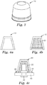
- Figs. 3 and 4a each represent an embodiment of a seal cap 10 .
- the seal caps according to the present invention are translucent.
- the term "translucent” means able to transmit some portion of visible light, typically greater than 20% of light in the 360-750 nm wavelength range, in some embodiments greater than 30%, in some embodiments greater than 40%, and in some embodiments greater than 50%.
- seal caps according to the present invention may be optically transparent, meaning transparent to the extent that the article does not prevent a viewer from resolving an image, e.g., reading text.
- seal caps according to the present invention permit visual inspection for flaws in construction or installation or both.
- the seal caps are made of a material having a dielectric breakdown strength of greater than 1.0 kV/mm, in some embodiments greater than 5.0 kV/mm, in some embodiments greater than 10.0 kV/mm, in some embodiments greater than 15.0 kV/mm, in some embodiments greater than 30.0 kV/mm, in some embodiments greater than 40.0 kV/mm, and in some embodiments greater than 50.0 kV/mm.
- the use of a material having a higher dielectric breakdown strength permits the manufacture of a lighter seal cap.
- the seal caps are thin-walled. In some embodiments, the seal caps have an average wall thickness of less than 1.5 mm, in some embodiments less than 1.2 mm, in some embodiments less than 1.0 mm, in some embodiments less than 0.5 mm, in some embodiments less than 0.2 mm, in some embodiments less than 0.1 mm, and in some embodiments less than 0.08 mm.
- the seal caps comprise a polythioether polymer or a polysulfide polymer.
- the material is jet fuel resistant.
- the material has a TB (brittle temperature) below -20°C.
- the seal cap comprises a mixture of a polymer and a nanoparticulate curative.
- the seal cap comprises no fillers or other particulates having an average particle size greater than 10 nm, in some embodiments not greater than 5 nm, and in some embodiments not greater than 1 nm.
- the seal cap and sealant comprise different materials. In some embodiments, the seal cap and sealant do not comprise different materials.
- the seal cap is at least partially filled with sealant.
- seal cap 10 may be filled with sealant 20 .
- the seal cap is at least partially filled with sealant shortly before use.
- the seal cap is at least partially filled with sealant and stored in ready-to-use form.
- a filled or partially filled cap is stored at low temperature.
- the filled or partially filled cap must be thawed before use.
- the seal cap is at least partially filled with sealant prior to application to a fastener.
- the seal cap is at least partially filled with sealant after application to a fastener, e.g., by syringe, by a sealant port, or the like. In some embodiments, the seal cap is applied to a fastener after application of sealant to the fastener. In some embodiments, the fastener penetrates a substrate article. In some embodiments, the fastener protrudes from a surface of a substrate article. In some embodiments the substrate article is a composite material. In some embodiments, the substrate article is an epoxy matrix and glass or carbon fiber composite material. In some embodiments, every portion of the fastener which protrudes from the substrate article is covered by cured sealant or seal cap or both. In some embodiments, every portion of the fastener which protrudes from the substrate article is covered by cured sealant.
- seal cap 10 filled with sealant 20 covers fastener 30 which protrudes from substrate article 40 . Some excess amount of sealant 22 may be pressed out of seal cap 10 during application.
- the sealant may be any suitable material.
- the material is jet fuel resistant.
- the material has a TB (brittle temperature) below -20°C.
- the sealant comprises a polyurethane polymer.
- the sealant comprises a polythioether polymer.
- the sealant comprises a polysulfide polymer.
- the sealant comprises a mixture of a polymer and a nanoparticulate filler.
- the sealant comprises a mixture of a polymer and a nanoparticulate curative.
- the seal cap comprises no fillers or other particulates having an average particle size greater than 10 nm, in some embodiments not greater than 5 nm, and in some embodiments not greater than 1 nm.
- the seal cap material and sealant material may be chosen such that strong bonds are formed between the sealant and the seal cap.
- the sealant material may be chosen such that strong bonds are formed between the sealant and the substrate.
- the sealant material may be chosen such that strong bonds are formed between the sealant and the fastener.
- the sealant is typically cured.
- the sealant is a radiation cured sealant.
- the sealant is cured by application of actinic radiation to the sealant.
- the sealant is cured by application of green light to the sealant.
- the sealant is cured by application of blue light to the sealant.
- the sealant is cured by application of violet light to the sealant.
- the sealant is cured by application of UV light to the sealant.
- the sealant is cured by application of radiation to the sealant through a translucent seal cap.
- the sealant is substantially fully cured in less than 60 seconds, in some embodiments less than 30 seconds, and in some embodiments less than 10 seconds.
- cure is accomplished by addition of a curing agent shortly prior to use.
- cure is accomplished by heat cure at ambient conditions.
- cure is accomplished by heat cure by application of heat from a heat source.
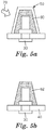
- a combination seal and seal cap are molded in place over a fastener using a seal cap mold.
- the seal cap mold is translucent or transparent to allow inspection and radiation cure of the form-in place seal and seal cap.
- Fig. 5a depicts one embodiment of such a process, wherein seal cap mold 50 containing sealant 60 is located over fastener 30 which protrudes from substrate article 40 .
- sealant 60 is cured by application of radiation 70 .
- Fig. 5b depicts the completed seal 62 after removal of seal cap mold 50.
- a liquid polythioether polymer was prepared as follows: Into a 1-liter round bottom flask equipped with an air driven stirrer, thermometer, and a dropping funnel, was added 407.4 grams (2.24 moles) DMDO, 12.63 grams (0.05 moles) TAC and 0.1 grams of VAZO-67. This mixture was stirred at 60°C for approximately 45 minutes. To this mixture, 380 grams (1.88 moles) DVE-3 was added drop wise over 45 minutes. Additional 0.3 grams VAZO-67 was added in small increments and the mixture was heated at 70 - 80°C for about 6 hours, followed by 10 minutes of vacuum degassing at 100°C. The resulting liquid polythioether polymer had a T g of less than -40°C, a viscosity of 100 Poise (10 Pa.s) and a thiol equivalent weight of 1,291 grams/equivalent.
- Composite panels for lighting strike testing and seal cap installation were made using the follow materials and methods.
- a layer of woven graphite fabric, type "CYCOM 970/PWC T300 3K NT" from Cytec Industries, Inc., Woodland Park, New Jersey was placed on each side of the 10-ply stack of pre-preg.
- the panel's size was nominally 12 by 12 inches (30.48 by 30.48 cm).
- the lay-up was then bagged using standard autoclave bagging practices and cured in an autoclave at 90 psi (620.5 kPa) under full vacuum at 350°F (176.7°C) for 2 hours.
- the panels were then cut in half and match drilled with ten holes to take Hi-Shear fastener shanks, Part No. "HL10VAZ6-3", obtained from Peerless Aerospace Fastener Co., Farmington, New York.
- the panels were drilled such that there was an overlap of 1 inch (2.54 cm) with the fasteners uniformly spaced along the center of the overlap joint.
- the two panels halves were joined together using the above mentioned shank and collar assembly, Part No. "HL94W6", also from Peerless Aerospace Fastener Co.
- the joint was wetted with AC-240 placed between the two panels and into the holes before tightening the fasteners.
- the final test panel had 10 fasteners centrally located in the overlap joint spaced uniformly across its 10 inch (25.4 cm) width.
- Composite panels having test fasteners covered with seal caps of the present invention was electrically grounded at the ends opposite the overlap joint.
- the cap side of the panel was placed inside a dark box, with a high speed camera positioned to record the event.
- the electrode was positioned 1.0 inches (2.54 cm) distant from the panel and directly opposite the target fastener on the outside of the dark box.
- An igniter wire was used to direct the arc to attach to the target fastener.
- 21kA to 103kA peak amplitude was imposed as the "D" bank component as described in SAE ARP1512.
- the "B” and “C” components were not used for this test.
- Various voltages were applied for each test and recorded. The pass fail for the tests was based on observed light in the dark box around the fastener.
- Optical transmission was used to measure the opacity of the cured seal caps.
- a bench top colorimeter, model "COLOR I” obtained from X-Rite, Inc., Grand Rapids, Michigan, with a measuring range of 750-360 nm in 10 nm increments, used the full frequency sweep and averaged to give a single value for percent transmission.
- An appropriate aperture was selected in the machine to give the maximum area for transmission while being able to hold the cap in the aperture.
- the equipment was calibrated using standard methods.
- the output from the test is a transmission value for each frequency from 360 nm to 750 nm. Table 2 shows the data as an average of the 360-750 nm frequency range.
- Translucent polyurethane seal caps were prepared as follows: A Shore 80 polyurethane casting compound, obtained under the trade designation "SMOOTH-ON CRYSTAL CLEAR 200" from McMaster-Carr Supply Company, Elmhurst, Illinois, was then poured into the female tool of a 6 by 8 inch (15.24 by 20.32 cm) 4-cavity stainless-steel seal cap mold, the cavities were designed to give a frusto-conical shaped cap with a base diameter of 27mm, a height of 23mm and a wall thickness of 2.5mm. The male tool closed the mold and the casting compound cured at 70°F (21.1°C) for 24 hours. The resulting translucent seal cap was then removed from the tool.
- a Shore 80 polyurethane casting compound obtained under the trade designation "SMOOTH-ON CRYSTAL CLEAR 200" from McMaster-Carr Supply Company, Elmhurst, Illinois, was then poured into the female tool of a 6 by 8 inch (15.24 by 20.32 cm) 4-cavity stainless-steel seal
- Translucent polythioether seal caps were prepared as follows: 100 grams PTE-1 was homogeneously mixed with 6.78 grams GE-30, 4.52 grams E-8220 and 1.00 grams DABCO-33LV. Part of this mixture was then poured into the female tool of the 6 by 8 inch (15.24 by 20.32 cm) 4-cavity stainless-steel seal cap mold. The male tool closed the mold and the mixture cured for 6 hours at 60°C. The resulting translucent seal cap was then removed from the tool.
- Translucent polythioether seal caps were prepared as follows: 100 grams PTE-2 was homogeneously mixed with 6.78 grams GE-30, 4.52 grams E-8220 and 1.00 gram DABCO-33LV. Part of this mixture was then poured into the female tool of an 8 by 8 inch (20.32 by 20.32 cm) 9-cavity aluminum seal cap mold, the cavities were designed to give a frusto-conical shaped cap with a base diameter of 15mm a height of 15mm and a wall thickness of 2.5mm. The male tool closed the mold and the mixture cured for 3 hours at 75°F (23.9°C), followed by 1 hour at 130°F (54.4°C), after which the mold was cooled to 70°F (21.1°C) before opening. The resulting translucent seal cap was then removed from the tool.
- Example 3 The process generally described in Example 3 was repeated, wherein the polymer mixture was allowed to pre-react for 2 hours before closing the mold and curing. The resulting translucent seal cap was then removed from the tool.
- a 40 ml. amber glass vial was charged with 7.055 grams DMDO, 5.252 grams DVE-2 and 0.914 grams TAC at 21°C. To this was added 0.132 grams I-819. The vial was then sealed and placed on a laboratory roller mill for 10 minutes until the I-819 had dissolved.
- the curable composition was injected into the female tool of the 8 by 8 inch (20.32 by 20.32 cm) 9-cavity aluminum seal cap mold, and a clear epoxy male tool was used to close the mold.
- the mixture was then cured by exposure, through the male tool, to a 455 nm LED light source, model "CF 2000" from Clearstone Technologies, Inc., Minneapolis, Minnesota, for 1 minute at a distance of 0.2 inches (0.51 cm). The resulting translucent seal cap was then removed from the tool.
- a 50:50 by weight mixture of THV-200 and MEK was brushed onto a single impression male tool dimensioned to give a frusto-conical shaped cap with a base diameter of 10mm and a height of 10mm and allowed to dry at 70°F (21.1°C) for approximately 60 minutes.
- a second application of the fluoroelastomer solution was applied to the male tool and again allowed to dry giving a wall thickness of about 0.25mm. The resulting light weight translucent seal cap was then removed from the tool and trimmed.
- a curable polythioether composition was prepared as follows. A 40 ml. amber glass vial was charged with 7.000 grams DMDO, 4.349 grams DVE-2 and 1.812 grams TAC at 21°C. To this was added 0.132 grams I-819. The vial was then sealed and placed on a laboratory roller mill for 10 minutes until the I-819 had dissolved.
- a UV curable seal cap was made as follows. The curable composition was injected into the female tool of the 8 by 8 inch (20.32 by 20.32 cm) 9-cavity aluminum seal cap mold. A clear epoxy male tool was then used to close the mold and the composition cured by exposure, through the male tool, to the 455 nm LED for 1 minute at a distance of 0.2 inches (0.51 cm). The resulting translucent seal cap was then removed from the tool.
- a curable polythioether composition was prepared as generally described in Example 7, wherein after the resin arid initiator were dissolved, 1.329 grams A-200 was homogeneously dispersed in the composition by means of a high speed mixer for 1 minute.
- a UV curable seal cap was made as follows. The curable composition was injected into the female tool of the 8 by 8 inch (20.32 by 20.32 cm) 9-cavity aluminum seal cap mold. A clear epoxy male tool was then used to close the mold and the composition was cured by exposure, through the male tool, to the 455 nm LED for 1 minute at a distance of 0.2 inches (0.51 cm). The resulting translucent seal cap was then removed from the tool.
- a curable polythioether composition was prepared as generally described in Example 7, wherein after the resin and initiator were dissolved, 1.329 grams DSW was homogeneously dispersed in the composition by means of a high speed mixer for 1 minute.
- a UV curable seal cap was made as follows. The curable composition was injected into the female tool of the 8 by 8 inch (20.32 by 20.32 cm) 9-cavity aluminum seal cap mold. A clear epoxy male tool was then used to close the mold and the composition was cured by exposure, through the male tool, to the 455 nm LED for I minute at a distance of 0.2 inches (0.51 cm). The finished cap was removed from the tool providing a translucent seal cap.
- a curable polythioether composition was prepared as generally described in Example 9, wherein the amount of DSW was increased to 2.659 grams.
- a UV curable seal cap was made as follows. The curable composition was injected into the female tool of the 8 by 8 inch (20.32 by 20.32 cm) 9-cavity aluminum seal cap mold. A clear epoxy male tool was then used to close the mold and the composition was cured by exposure, through the male tool, to the 455 nm LED for 1 minute at a distance of 0.2 inches (0.51 cm). The resulting translucent seal cap was then removed from the tool.
- a curable polythioether composition was prepared as generally described in Example 9, wherein the amount of DSW was increased to 3.988 grams.
- a UV curable seal cap was made as follows. The curable composition was injected into the female tool of the 8 by 8 inch (20.32 by 20.32 cm) 9-cavity aluminum seal cap mold. A clear epoxy male tool was then used to close the mold and the composition was cured by exposure, through the male tool, to the 455 nm LED for 1 minute at a distance of 0.2 inches (0.51 cm). The resulting translucent seal cap was then removed from the tool.
- a curable polythioether composition was prepared as follows. A 40 ml. amber glass vial was charged with 7.000 grams DMDO, 5.212 grams DVE-2 and 0.289 grams ODY at 21°C. To this was added 0.125 grams 1-819. The vial was then sealed and placed on a laboratory roller mill for 10 minutes until the I-819 had dissolved. The curable composition was injected into the female tool of the 8 by 8 inch (20.32 by 20.32 cm) 9-cavity aluminum seal cap mold. A clear epoxy male tool was then used to close the mold and the composition was cured by exposure, through the male tool, to the 455 nm LED for 1 minute at a distance of 0.2 inches (0.51 cm). The resulting translucent seal cap was then removed from the tool.
- a curable polythioether composition was prepared as generally described in Example 7, wherein after the resin and initiator were dissolved, 1.329 grams NCC was homogeneously dispersed in the composition by means of a high speed mixer for 1 minute.
- a UV curable seal cap was made as follows. The curable composition was injected into the female tool of the 8 by 8 inch (20.32 by 20.32 cm) 9-cavity aluminum seal cap mold. A clear epoxy male tool was then used to close the mold and the composition was cured by exposure, through the male tool, to the 455 nm LED for 1 minute at a distance of 0.2 inches (0.51 cm). The resulting translucent seal cap was then removed from the tool.
- AC-380 sealant mixture was prepared in a 10:1 base: accelerator weight ratio at 70°F (21.1°C) and injected into the female tooling of the 8 by 8 inch (20.32 by 20.32 cm) 9-cavity aluminum seal cap mold. The male tooling closed the mold and the sealant was cured for approximately 12 hours at 75°F (23.9°C), followed by 1 hour at 130°F (54.4°C), after which the mold was cooled to room temperature before opening and removing the opaque seal caps.
- a white fluorinated polymer film was prepared by feeding a uniform mixture of pellets having 97 weight percent THV-500 and 3 weight percent THV-200W into a 1.9 cm Haake extruder. The extruder was run to give a uniform 43 ⁇ m film supported by a 127 ⁇ m polyethylene backing film. The caps were made using a vacuum forming table. The unsupported THV film was positioned and clamped over the single impression male tool, on the vacuum table. The film was then heated to 400°F (204.4°C) using radiant heat. After the film started to sag the tool was driven up into the film and a vacuum applied to pull the film over the tool. The opaque film was allowed to cool to 21°C, removed from the male tool and trimmed, resulting in an opaque seal cap.
- a clear resin was made as follows. 100 grams PTE-2 was homogeneously mixed with 6.78 grams GE-30, 4.52 grams E-8220 and 1.00 gram DABCO-33LV at 21°C. Part of this mixture was then poured into a translucent polythioether seal cap made according to Example 3. The filled seal cap assembly was then placed onto a fastener on the composite panel and cured at 21°C for 24 hours. This resulted in a fastener protected by a translucent cured seal cap.
- Example 3 The translucent seal cap of Example 3 was filled with opaque resin AC-360. The filled seal cap assembly was then placed onto a fastener on the composite panel and cured at 21°C for 24 hours. This resulted in a fastener protected by a translucent cured cap with an opaque internal sealant.
- a UV curable thiol-yne resin was prepared as follows. A 40 ml. amber glass vial was charged with 7.000 grams DMDO, 5.212 grams DVE-2 and 0.2894 grams ODY at 21°C. To this was added 0.125 grams I-819. The vial was then sealed and placed on a laboratory roller mill for 10 minutes until the 1-819 had dissolved. Part of this mixture was then poured into a translucent seal cap made according to Example 5. The filled seal cap assembly was then placed onto a fastener on the composite panel and cured by exposure to the 455 nm LED for 30 seconds at a distance of approximately 1 inch (2.54 cm) from the composite panel. This resulted in a fastener protected by a translucent cured seal cap.
- a clear thiol-ene resin composition was prepared as follows. A 40 ml. amber glass vial was charged with 7.000 grams DMDO, 4.3494 grams DVE-2 and 1.8124 grams TAC at 21°C. To this was added 0.132 grams I-819. The vial was then sealed and placed on a laboratory roller mill for 10 minutes until the 1-819 had dissolved. Part of this mixture was then poured into a translucent seal cap made according to Example 6. The filled seal cap assembly was then placed onto a fastener on the composite panel and cured by exposure to the 455 nm LED for 30 seconds at a distance of approximately 1 inch (2.54 cm) from the composite panel. This resulted in a fastener protected by a translucent cured seal cap.
- Example 6 The translucent seal cap of Example 6 was filled with opaque resin AC-240. The filled seal cap assembly was then placed onto a fastener on the composite panel and cured at 21°C for 24 hours. This resulted in a fastener protected by a translucent cured seal cap with an opaque sealant.
- a fastener protected by a translucent cured seal cap was made according to the general procedure described in Example 21, wherein the translucent seal cap Example 6 was substituted with a translucent seal cap made according to Example 3.
- a fastener protected by a translucent cured seal cap was prepared as generally described in Example 20, wherein the translucent seal cap made according to Example 5 was substituted with a translucent seal cap made according to Example 12.
- a curable thiol-ene resin composition was prepared as follows. A 40 ml. amber glass vial was charged with 7.000 grams DMDO, 4.439 grams DVE-2 and 1.812 grams TAC at 21°C. To this was added 0.132 grams 1-819. The vial was then sealed and placed on a laboratory roller mill for 10 minutes until the I-819 had dissolved. The thiol-ene sealant formulation was injected into release coated, 13.5 mm diameter by 12 mm high, frusto-conical quartz glass cap mold. The cap was then placed onto a fastener on the composite panel and cured by exposure to the 455 nm LED for 30 seconds at a distance of approximately 1 inch (2.54 cm) from the composite panel. After curing the quartz glass cap mold was released, resulting in a fastener protected by a translucent cured seal cap.
- a fastener protected by a translucent cured seal cap was prepared as generally described in Example 25, wherein the thiol-ene chemistry was substituted by a thiol-yne chemistry as follows.
- Curable polythioether composition was prepared as follows. A 40 ml. amber glass vial was charged with 7.000 grams DMDO, 5.212 grams DVE-2 and 0.2894 grams ODY at 21°C. To this was added 0.125 grams 1-819. The vial was then sealed and placed on a laboratory roller mill for 10 minutes until the I-819 had dissolved.
- the opaque seal cap of Comparative A was filled with opaque resin AC-380.
- the filled seal cap assembly was then placed onto a fastener on the composite panel and cured at 21°C for 24 hours. This resulted in a fastener protected by an opaque cured seal cap with an opaque sealant.
- a sheet of APTIV brand PEEK film was positioned over the single impression male tool that had been pre-heated to 200°C.
- the film was then softened and deformed over the male tool by means of a hot air gun.
- a pre-formed cap was then pressed over the softened film and male tool, after which the assembly was cooled to approximately 21°C.
- the pre-formed cap was then removed, revealing a light weight, translucent PEEK film cap, which was then removed from the male tool and trimmed.
- a filled translucent seal cap was prepared as generally described in Example 18, wherein the polythioether seal cap was replaced by a PEEK seal cap made according to Example 27.
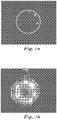
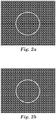
- Figs. 1-2 are exemplary photographs of Examples 18, Test No. 2 and Comparative E, Test No. 3, respectively, of the lightning strike tests.
- the translucent cap and translucent filler enabled observation of the plasma formation on the fastener inside the cap.
- TABLE 1 Example Test # Peak Current kA Pass / Fail Example 18 1 27 Pass 2 34 Pass 3 40 Pass Example 19 1 28 Pass 2 34 Pass Comparative E 1 27 Pass 2 28 Pass 3 33 Pass TABLE 2 Example Observed color Subjective assessment of opacity % Average Transmission (360-750 nm) Control (Air) 100.17
- Example 7 Clear Clear 51.81 Example 5 Clear Clear 51.24
- Example 9 Milky white Translucent 46.40
- Example 8 Milky white Translucent 44.42
- Example 10 Milky white Translucent 33.76
- Example 14 White Opaque 15.56 Comparative D White Opaque 11.
- Fig. 1 demonstrates a lightning strike test on Example 18; test number 2.
- the red circle on each photo shows the outside edge of the seal cap.
- the images progress from top left: the start of the strike, top right: full intensity plasma, discharge was contained within the cap, light outside the cap are reflections on other surfaces. Bottom left the plasma starting to decay and bottom right close to completion of the strike.
- Fig. 2 demonstrates a lightning strike test on Comparative E; test number 3.
- the images progress in the same sequence as Example 18 in Fig. 1 .
- the seal cap is opaque, the plasma discharge and decay cannot be observed.
Landscapes
- Engineering & Computer Science (AREA)
- General Engineering & Computer Science (AREA)
- Aviation & Aerospace Engineering (AREA)
- Mechanical Engineering (AREA)
- Sealing Material Composition (AREA)
- Casting Or Compression Moulding Of Plastics Or The Like (AREA)
- Lining Or Joining Of Plastics Or The Like (AREA)
Applications Claiming Priority (2)
| Application Number | Priority Date | Filing Date | Title |
|---|---|---|---|
| US201361811983P | 2013-04-15 | 2013-04-15 | |
| PCT/US2014/034070 WO2014172302A1 (en) | 2013-04-15 | 2014-04-15 | Translucent seal cap |
Publications (2)
| Publication Number | Publication Date |
|---|---|
| EP2986510A1 EP2986510A1 (en) | 2016-02-24 |
| EP2986510B1 true EP2986510B1 (en) | 2020-07-29 |
Family
ID=50686238
Family Applications (1)
| Application Number | Title | Priority Date | Filing Date |
|---|---|---|---|
| EP14722961.1A Active EP2986510B1 (en) | 2013-04-15 | 2014-04-15 | Translucent seal cap |
Country Status (8)
| Country | Link |
|---|---|
| US (4) | US9650150B2 (enExample) |
| EP (1) | EP2986510B1 (enExample) |
| JP (2) | JP2016518271A (enExample) |
| KR (1) | KR20150143646A (enExample) |
| CN (1) | CN105143045B (enExample) |
| BR (1) | BR112015026218A2 (enExample) |
| CA (1) | CA2909366A1 (enExample) |
| WO (1) | WO2014172302A1 (enExample) |
Families Citing this family (26)
| Publication number | Priority date | Publication date | Assignee | Title |
|---|---|---|---|---|
| JP2016518271A (ja) * | 2013-04-15 | 2016-06-23 | スリーエム イノベイティブ プロパティズ カンパニー | 半透明シールキャップ |
| BR112015026212A2 (pt) | 2013-04-15 | 2017-07-25 | 3M Innovative Properties Co | tampa de vedação leve |
| CA2909937C (en) * | 2013-04-22 | 2017-07-11 | Prc-Desoto International, Inc. | Sealant caps including internal barrier rings |
| BR112017013846A2 (pt) * | 2014-12-24 | 2018-01-02 | 3M Innovative Properties Co | método para preenchimento de espaços vazios em uma tampa de vedação preenchida |
| US11167310B2 (en) * | 2015-05-13 | 2021-11-09 | The Boeing Company | Sealing assembly for forming sealant coating on a fastener, the sealing assembly comprising a light generator and a forming cup associated with the light generator |
| US10760609B2 (en) * | 2016-02-08 | 2020-09-01 | Hamilton Sundstrand Corporation | Sealant articles and method of applying sealant |
| US10087974B2 (en) | 2016-12-06 | 2018-10-02 | David Szymczak | Protection cap assembly for one or more bolts |
| CN116428255A (zh) | 2017-04-03 | 2023-07-14 | 凯密特尔有限责任公司 | 用作对燃料和液压油以及雷击的组合保护的密封复合物填充的塑料盖 |
| JP2020535257A (ja) * | 2017-09-26 | 2020-12-03 | スリーエム イノベイティブ プロパティズ カンパニー | 硬化性シーラント組成物、シールキャップ、並びにその作製方法及び使用 |
| JP2019086129A (ja) | 2017-11-09 | 2019-06-06 | 三菱重工業株式会社 | シール方法、組立体、及び組立体の製造方法 |
| US20210198535A1 (en) | 2017-12-22 | 2021-07-01 | 3M Innovative Properties Company | Multilayered polyetherketoneketone articles and methods thereof |
| US11648761B2 (en) | 2018-04-17 | 2023-05-16 | 3M Innovative Properties Company | Conductive films |
| WO2019234693A1 (en) | 2018-06-07 | 2019-12-12 | 3M Innovative Properties Company | Lightning strike protection film |
| US20210252830A1 (en) | 2018-06-15 | 2021-08-19 | 3M Innovative Properties Company | Assemblies and methods of making a shim |
| JP2020020387A (ja) | 2018-07-31 | 2020-02-06 | 三菱重工業株式会社 | キャップシール、これを備えた締結構造、及びキャップシールの装着方法 |
| EP3626442A1 (en) * | 2018-09-20 | 2020-03-25 | BAE SYSTEMS plc | Method and apparatus for producing a seal |
| WO2020058699A1 (en) * | 2018-09-20 | 2020-03-26 | Bae Systems Plc | Sealing method and apparatus for sealing |
| EP3626443A1 (en) * | 2018-09-20 | 2020-03-25 | BAE SYSTEMS plc | Sealing method and apparatus for sealing |
| WO2020123037A1 (en) * | 2018-10-22 | 2020-06-18 | Nylok Llc | Fastener sealing material and method |
| CN110374977A (zh) * | 2019-07-20 | 2019-10-25 | 中国船舶重工集团公司第七二四研究所 | 舰船用紧固件的快速安装式腐蚀防护方法 |
| CN114174049A (zh) | 2019-07-25 | 2022-03-11 | 3M创新有限公司 | 对组件填垫的方法 |
| GB2608394A (en) * | 2021-06-29 | 2023-01-04 | Airbus Operations Ltd | Spark containment cap |
| GB202114707D0 (en) | 2021-08-28 | 2021-12-01 | Airbus Sas | Landing system and method |
| CN114670374B (zh) * | 2022-04-08 | 2023-10-24 | 成都希瑞方晓科技有限公司 | 一种密封胶帽成型模具 |
| WO2023215049A1 (en) * | 2022-05-02 | 2023-11-09 | Encore Automation, LLC | Cap tool with load cell |
| KR102701760B1 (ko) * | 2022-11-15 | 2024-08-30 | 서원대학교산학협력단 | 시일 캡 |
Family Cites Families (55)
| Publication number | Priority date | Publication date | Assignee | Title |
|---|---|---|---|---|
| US2710113A (en) | 1952-01-23 | 1955-06-07 | Gen Dynamics Corp | Seal construction |
| US2927495A (en) | 1957-02-20 | 1960-03-08 | Victor H Barwood | Composite self-sealing washer |
| US3411816A (en) * | 1966-11-22 | 1968-11-19 | Gen Motors Corp | Double sealing nut |
| US3470787A (en) * | 1968-03-27 | 1969-10-07 | Us Army | Corrosion prevention device and method |
| JPS5014966A (enExample) * | 1973-06-12 | 1975-02-17 | ||
| US4400123A (en) | 1980-07-14 | 1983-08-23 | Rodun Development Corporation | Nut and thread protector |
| AU566422B2 (en) * | 1981-10-15 | 1987-10-22 | Thompson, W.H. | A polymerisable fluid |
| US4382049A (en) | 1981-11-30 | 1983-05-03 | Mcdonnell Douglas Corporation | Forming a lightning spark isolation barrier |
| JPS596410A (ja) * | 1982-06-30 | 1984-01-13 | 九州日立マクセル株式会社 | 被締結体にねじ・くぎ類を仮止めする方法 |
| US4519974A (en) * | 1983-08-12 | 1985-05-28 | Ltv Aerospace And Defense Company | Method and apparatus for applying a sealant to exposed fasteners |
| JPS6120566U (ja) * | 1984-07-06 | 1986-02-06 | 日本電信電話株式会社 | 支持金物の接続構造 |
| EP0181483B1 (en) * | 1984-10-15 | 1990-01-10 | Ltv Aerospace And Defense Company | Method and apparatus for applying a precision amount of sealant to exposed fasteners |
| JPS61196008A (ja) * | 1985-02-25 | 1986-08-30 | 株式会社スリーボンド | 突起危険物の被覆方法 |
| JPH0274612A (ja) | 1988-09-07 | 1990-03-14 | Toray Ind Inc | 高強度複合繊維 |
| US4826380A (en) * | 1988-01-19 | 1989-05-02 | Ltv Aerospace & Defense Company | Pre-cast sealant dome and method |
| JPH02138488A (ja) * | 1988-11-18 | 1990-05-28 | Dainippon Toryo Co Ltd | ボルト・ナットの防食方法 |
| JPH0610182Y2 (ja) * | 1988-11-29 | 1994-03-16 | 株式会社愛洋産業 | 光硬化性被覆キャップ |
| US4905631A (en) | 1989-02-27 | 1990-03-06 | Combustion Engineering, Inc. | Moisture separator reheater with inlet diffuser for steam distribution |
| JPH065083B2 (ja) * | 1989-08-09 | 1994-01-19 | 大日本塗料株式会社 | ボルト・ナットの防食法及び保護キャップ |
| JP2960636B2 (ja) | 1993-11-02 | 1999-10-12 | 早川ゴム株式会社 | 保護部材 |
| JPH0893737A (ja) * | 1994-09-19 | 1996-04-09 | Nitto Seiko Co Ltd | 頭部樹脂付着ねじ |
| JPH08240215A (ja) * | 1995-03-06 | 1996-09-17 | Maruyoshi:Kk | ボルト・ナット用又は端子台用危険温度標示キャップ |
| JP3490810B2 (ja) * | 1995-10-18 | 2004-01-26 | 関西ペイント株式会社 | ボルト部及びナット部の防食被覆方法 |
| US5697745A (en) | 1995-12-05 | 1997-12-16 | Shaw; Jack B. | Screw cap |
| US5755908A (en) | 1996-02-21 | 1998-05-26 | Rayburn; Herbert | Moldable self-adhering fastener cover and installation method |
| US6086972A (en) * | 1996-02-21 | 2000-07-11 | Rayburn; Herbert | Deformable self-adhering fastener cover and installation method |
| US6036804A (en) | 1996-02-21 | 2000-03-14 | Rayburn; Herbert | Moldable self-adhering fastener cover and installation method |
| JPH11132217A (ja) * | 1997-10-28 | 1999-05-18 | Ube Kimitsu Housing Kk | 断熱用ボルトカバ− |
| JP2002227819A (ja) * | 2001-02-06 | 2002-08-14 | Ishikawajima Harima Heavy Ind Co Ltd | 防錆用ボルトナットキャップ |
| CA2461671C (en) | 2001-09-28 | 2010-09-14 | Prc-Desoto International, Inc. | Premixed and frozen seal caps |
| US7479653B2 (en) * | 2003-12-04 | 2009-01-20 | Henkel Ag & Co Kgaa | UV curable protective encapsulant |
| ES2541450T3 (es) * | 2005-03-18 | 2015-07-20 | Kuraray Co., Ltd. | Resina de poliamida semiaromática |
| GB0624562D0 (en) * | 2006-12-08 | 2007-01-17 | Airbus Uk Ltd | Self Curing Injection Nozzle |
| KR101376319B1 (ko) * | 2007-07-27 | 2014-03-20 | 주식회사 동진쎄미켐 | 디스플레이 소자의 실링방법 |
| US20110272554A1 (en) | 2008-12-31 | 2011-11-10 | Kai Foo Chow | Mould for chairside casting of light cured composite (or other dental material) abutments onto mini dental implants |
| JP5610758B2 (ja) * | 2009-04-02 | 2014-10-22 | 三菱航空機株式会社 | 耐雷ファスナ、キャップ、耐雷ファスナの取り付け方法、航空機 |
| JP5489774B2 (ja) * | 2010-02-23 | 2014-05-14 | 三菱重工業株式会社 | 耐雷ファスナ |
| US9533798B2 (en) * | 2010-08-13 | 2017-01-03 | Prc-Desoto International, Inc. | Uses of UV-curable polythioether sealants for sealing fasteners and for smoothing surfaces |
| CA2816864A1 (en) * | 2010-11-02 | 2012-05-10 | Systems And Materials Research Corporation | Method and apparatus for making and using a self-sealing fastener |
| JP5487093B2 (ja) * | 2010-12-17 | 2014-05-07 | 三菱航空機株式会社 | 耐雷ファスナ、耐雷ファスナの取付構造、航空機 |
| EP3366593B1 (en) * | 2011-02-10 | 2019-10-23 | Airbus Operations Limited | Cap for forming sealed cavity around fastener |
| US8388293B2 (en) * | 2011-02-28 | 2013-03-05 | Physical Systems, Inc. | Insulated and sealed cap for a fastener component |
| JP5611097B2 (ja) * | 2011-03-30 | 2014-10-22 | 三菱航空機株式会社 | 耐雷防爆用ファスナ |
| US20130223951A1 (en) | 2011-04-28 | 2013-08-29 | Masahiro Bessho | Cap and fixing structure using the same |
| JP5187985B1 (ja) * | 2011-11-04 | 2013-04-24 | 三菱航空機株式会社 | 耐雷ファスナ、耐雷ファスナのキャップ |
| US8717735B2 (en) * | 2011-12-14 | 2014-05-06 | The Boeing Company | Seal with energy-absorbing filler and method of manufacture |
| JP5931458B2 (ja) * | 2012-01-17 | 2016-06-08 | 三菱航空機株式会社 | 耐雷ファスナ、耐雷ファスナの装着方法 |
| MX347916B (es) * | 2012-03-08 | 2017-05-17 | Jurblami S L | Molde de campanilla para encapsulados con sellante moldeable. |
| CN102678927A (zh) * | 2012-05-22 | 2012-09-19 | 西安飞机工业(集团)有限责任公司 | 一种紧固件的密封工艺方法 |
| US10051767B2 (en) * | 2012-09-28 | 2018-08-14 | The Boeing Company | Method and apparatus for covering a fastener system |
| US9140291B2 (en) * | 2012-09-28 | 2015-09-22 | The Boeing Company | Apparatus for covering a fastener system |
| JP6190142B2 (ja) * | 2013-04-12 | 2017-08-30 | 関西電力株式会社 | 防食樹脂モールドの施工方法 |
| JP2016518271A (ja) * | 2013-04-15 | 2016-06-23 | スリーエム イノベイティブ プロパティズ カンパニー | 半透明シールキャップ |
| BR112015026212A2 (pt) * | 2013-04-15 | 2017-07-25 | 3M Innovative Properties Co | tampa de vedação leve |
| GB2514171B (en) * | 2013-05-16 | 2015-11-25 | Airbus Operations Ltd | Injectable nut cap |
-
2014
- 2014-04-15 JP JP2016509022A patent/JP2016518271A/ja active Pending
- 2014-04-15 CA CA2909366A patent/CA2909366A1/en not_active Abandoned
- 2014-04-15 CN CN201480021171.0A patent/CN105143045B/zh active Active
- 2014-04-15 WO PCT/US2014/034070 patent/WO2014172302A1/en not_active Ceased
- 2014-04-15 EP EP14722961.1A patent/EP2986510B1/en active Active
- 2014-04-15 BR BR112015026218A patent/BR112015026218A2/pt not_active Application Discontinuation
- 2014-04-15 US US14/783,913 patent/US9650150B2/en active Active
- 2014-04-15 KR KR1020157032276A patent/KR20150143646A/ko not_active Ceased
-
2017
- 2017-03-23 US US15/467,147 patent/US10183758B2/en active Active
-
2018
- 2018-11-29 JP JP2018223856A patent/JP2019056491A/ja active Pending
-
2019
- 2019-01-11 US US16/245,601 patent/US10858117B2/en active Active
-
2020
- 2020-11-13 US US17/097,573 patent/US20210061483A1/en not_active Abandoned
Non-Patent Citations (1)
| Title |
|---|
| None * |
Also Published As
| Publication number | Publication date |
|---|---|
| US20210061483A1 (en) | 2021-03-04 |
| CN105143045B (zh) | 2018-05-18 |
| US10858117B2 (en) | 2020-12-08 |
| CA2909366A1 (en) | 2014-10-23 |
| JP2019056491A (ja) | 2019-04-11 |
| WO2014172302A1 (en) | 2014-10-23 |
| EP2986510A1 (en) | 2016-02-24 |
| US20190144127A1 (en) | 2019-05-16 |
| CN105143045A (zh) | 2015-12-09 |
| US10183758B2 (en) | 2019-01-22 |
| US9650150B2 (en) | 2017-05-16 |
| BR112015026218A2 (pt) | 2017-07-25 |
| KR20150143646A (ko) | 2015-12-23 |
| JP2016518271A (ja) | 2016-06-23 |
| US20170190442A1 (en) | 2017-07-06 |
| US20160068274A1 (en) | 2016-03-10 |
Similar Documents
| Publication | Publication Date | Title |
|---|---|---|
| EP2986510B1 (en) | Translucent seal cap | |
| EP2986511B1 (en) | Light weight seal cap | |
| US10780657B2 (en) | Method of filling voids in a filled seal cap | |
| US9068583B2 (en) | Self-sealing fastener | |
| KR100695585B1 (ko) | 성형된 형태의 예비형성된 조성물 | |
| EP2617770A1 (en) | Resin composition sheet for encapsulating electronic parts and method of producing electronic part apparatus using the sheet | |
| US8568850B2 (en) | Frozen, lightweight curable sealant | |
| JPH11111741A (ja) | 光半導体素子封止用エポキシ樹脂タブレット及び該タブレットを用いて封止された光半導体装置 |
Legal Events
| Date | Code | Title | Description |
|---|---|---|---|
| PUAI | Public reference made under article 153(3) epc to a published international application that has entered the european phase |
Free format text: ORIGINAL CODE: 0009012 |
|
| 17P | Request for examination filed |
Effective date: 20151022 |
|
| AK | Designated contracting states |
Kind code of ref document: A1 Designated state(s): AL AT BE BG CH CY CZ DE DK EE ES FI FR GB GR HR HU IE IS IT LI LT LU LV MC MK MT NL NO PL PT RO RS SE SI SK SM TR |
|
| AX | Request for extension of the european patent |
Extension state: BA ME |
|
| DAX | Request for extension of the european patent (deleted) | ||
| STAA | Information on the status of an ep patent application or granted ep patent |
Free format text: STATUS: EXAMINATION IS IN PROGRESS |
|
| 17Q | First examination report despatched |
Effective date: 20180511 |
|
| GRAP | Despatch of communication of intention to grant a patent |
Free format text: ORIGINAL CODE: EPIDOSNIGR1 |
|
| STAA | Information on the status of an ep patent application or granted ep patent |
Free format text: STATUS: GRANT OF PATENT IS INTENDED |
|
| INTG | Intention to grant announced |
Effective date: 20200207 |
|
| GRAS | Grant fee paid |
Free format text: ORIGINAL CODE: EPIDOSNIGR3 |
|
| GRAA | (expected) grant |
Free format text: ORIGINAL CODE: 0009210 |
|
| STAA | Information on the status of an ep patent application or granted ep patent |
Free format text: STATUS: THE PATENT HAS BEEN GRANTED |
|
| AK | Designated contracting states |
Kind code of ref document: B1 Designated state(s): AL AT BE BG CH CY CZ DE DK EE ES FI FR GB GR HR HU IE IS IT LI LT LU LV MC MK MT NL NO PL PT RO RS SE SI SK SM TR |
|
| REG | Reference to a national code |
Ref country code: CH Ref legal event code: EP |
|
| REG | Reference to a national code |
Ref country code: AT Ref legal event code: REF Ref document number: 1295503 Country of ref document: AT Kind code of ref document: T Effective date: 20200815 |
|
| REG | Reference to a national code |
Ref country code: IE Ref legal event code: FG4D |
|
| REG | Reference to a national code |
Ref country code: DE Ref legal event code: R096 Ref document number: 602014068256 Country of ref document: DE |
|
| REG | Reference to a national code |
Ref country code: LT Ref legal event code: MG4D |
|
| REG | Reference to a national code |
Ref country code: NL Ref legal event code: MP Effective date: 20200729 |
|
| REG | Reference to a national code |
Ref country code: AT Ref legal event code: MK05 Ref document number: 1295503 Country of ref document: AT Kind code of ref document: T Effective date: 20200729 |
|
| PG25 | Lapsed in a contracting state [announced via postgrant information from national office to epo] |
Ref country code: PT Free format text: LAPSE BECAUSE OF FAILURE TO SUBMIT A TRANSLATION OF THE DESCRIPTION OR TO PAY THE FEE WITHIN THE PRESCRIBED TIME-LIMIT Effective date: 20201130 Ref country code: AT Free format text: LAPSE BECAUSE OF FAILURE TO SUBMIT A TRANSLATION OF THE DESCRIPTION OR TO PAY THE FEE WITHIN THE PRESCRIBED TIME-LIMIT Effective date: 20200729 Ref country code: NO Free format text: LAPSE BECAUSE OF FAILURE TO SUBMIT A TRANSLATION OF THE DESCRIPTION OR TO PAY THE FEE WITHIN THE PRESCRIBED TIME-LIMIT Effective date: 20201029 Ref country code: LT Free format text: LAPSE BECAUSE OF FAILURE TO SUBMIT A TRANSLATION OF THE DESCRIPTION OR TO PAY THE FEE WITHIN THE PRESCRIBED TIME-LIMIT Effective date: 20200729 Ref country code: GR Free format text: LAPSE BECAUSE OF FAILURE TO SUBMIT A TRANSLATION OF THE DESCRIPTION OR TO PAY THE FEE WITHIN THE PRESCRIBED TIME-LIMIT Effective date: 20201030 Ref country code: FI Free format text: LAPSE BECAUSE OF FAILURE TO SUBMIT A TRANSLATION OF THE DESCRIPTION OR TO PAY THE FEE WITHIN THE PRESCRIBED TIME-LIMIT Effective date: 20200729 Ref country code: SE Free format text: LAPSE BECAUSE OF FAILURE TO SUBMIT A TRANSLATION OF THE DESCRIPTION OR TO PAY THE FEE WITHIN THE PRESCRIBED TIME-LIMIT Effective date: 20200729 Ref country code: BG Free format text: LAPSE BECAUSE OF FAILURE TO SUBMIT A TRANSLATION OF THE DESCRIPTION OR TO PAY THE FEE WITHIN THE PRESCRIBED TIME-LIMIT Effective date: 20201029 Ref country code: HR Free format text: LAPSE BECAUSE OF FAILURE TO SUBMIT A TRANSLATION OF THE DESCRIPTION OR TO PAY THE FEE WITHIN THE PRESCRIBED TIME-LIMIT Effective date: 20200729 Ref country code: ES Free format text: LAPSE BECAUSE OF FAILURE TO SUBMIT A TRANSLATION OF THE DESCRIPTION OR TO PAY THE FEE WITHIN THE PRESCRIBED TIME-LIMIT Effective date: 20200729 |
|
| PG25 | Lapsed in a contracting state [announced via postgrant information from national office to epo] |
Ref country code: LV Free format text: LAPSE BECAUSE OF FAILURE TO SUBMIT A TRANSLATION OF THE DESCRIPTION OR TO PAY THE FEE WITHIN THE PRESCRIBED TIME-LIMIT Effective date: 20200729 Ref country code: RS Free format text: LAPSE BECAUSE OF FAILURE TO SUBMIT A TRANSLATION OF THE DESCRIPTION OR TO PAY THE FEE WITHIN THE PRESCRIBED TIME-LIMIT Effective date: 20200729 Ref country code: PL Free format text: LAPSE BECAUSE OF FAILURE TO SUBMIT A TRANSLATION OF THE DESCRIPTION OR TO PAY THE FEE WITHIN THE PRESCRIBED TIME-LIMIT Effective date: 20200729 Ref country code: IS Free format text: LAPSE BECAUSE OF FAILURE TO SUBMIT A TRANSLATION OF THE DESCRIPTION OR TO PAY THE FEE WITHIN THE PRESCRIBED TIME-LIMIT Effective date: 20201129 |
|
| PG25 | Lapsed in a contracting state [announced via postgrant information from national office to epo] |
Ref country code: NL Free format text: LAPSE BECAUSE OF FAILURE TO SUBMIT A TRANSLATION OF THE DESCRIPTION OR TO PAY THE FEE WITHIN THE PRESCRIBED TIME-LIMIT Effective date: 20200729 |
|
| PG25 | Lapsed in a contracting state [announced via postgrant information from national office to epo] |
Ref country code: IT Free format text: LAPSE BECAUSE OF FAILURE TO SUBMIT A TRANSLATION OF THE DESCRIPTION OR TO PAY THE FEE WITHIN THE PRESCRIBED TIME-LIMIT Effective date: 20200729 Ref country code: CZ Free format text: LAPSE BECAUSE OF FAILURE TO SUBMIT A TRANSLATION OF THE DESCRIPTION OR TO PAY THE FEE WITHIN THE PRESCRIBED TIME-LIMIT Effective date: 20200729 Ref country code: DK Free format text: LAPSE BECAUSE OF FAILURE TO SUBMIT A TRANSLATION OF THE DESCRIPTION OR TO PAY THE FEE WITHIN THE PRESCRIBED TIME-LIMIT Effective date: 20200729 Ref country code: EE Free format text: LAPSE BECAUSE OF FAILURE TO SUBMIT A TRANSLATION OF THE DESCRIPTION OR TO PAY THE FEE WITHIN THE PRESCRIBED TIME-LIMIT Effective date: 20200729 Ref country code: RO Free format text: LAPSE BECAUSE OF FAILURE TO SUBMIT A TRANSLATION OF THE DESCRIPTION OR TO PAY THE FEE WITHIN THE PRESCRIBED TIME-LIMIT Effective date: 20200729 Ref country code: SM Free format text: LAPSE BECAUSE OF FAILURE TO SUBMIT A TRANSLATION OF THE DESCRIPTION OR TO PAY THE FEE WITHIN THE PRESCRIBED TIME-LIMIT Effective date: 20200729 |
|
| REG | Reference to a national code |
Ref country code: DE Ref legal event code: R097 Ref document number: 602014068256 Country of ref document: DE |
|
| PG25 | Lapsed in a contracting state [announced via postgrant information from national office to epo] |
Ref country code: AL Free format text: LAPSE BECAUSE OF FAILURE TO SUBMIT A TRANSLATION OF THE DESCRIPTION OR TO PAY THE FEE WITHIN THE PRESCRIBED TIME-LIMIT Effective date: 20200729 |
|
| PLBE | No opposition filed within time limit |
Free format text: ORIGINAL CODE: 0009261 |
|
| STAA | Information on the status of an ep patent application or granted ep patent |
Free format text: STATUS: NO OPPOSITION FILED WITHIN TIME LIMIT |
|
| PG25 | Lapsed in a contracting state [announced via postgrant information from national office to epo] |
Ref country code: SK Free format text: LAPSE BECAUSE OF FAILURE TO SUBMIT A TRANSLATION OF THE DESCRIPTION OR TO PAY THE FEE WITHIN THE PRESCRIBED TIME-LIMIT Effective date: 20200729 |
|
| 26N | No opposition filed |
Effective date: 20210430 |
|
| PG25 | Lapsed in a contracting state [announced via postgrant information from national office to epo] |
Ref country code: SI Free format text: LAPSE BECAUSE OF FAILURE TO SUBMIT A TRANSLATION OF THE DESCRIPTION OR TO PAY THE FEE WITHIN THE PRESCRIBED TIME-LIMIT Effective date: 20200729 |
|
| REG | Reference to a national code |
Ref country code: DE Ref legal event code: R119 Ref document number: 602014068256 Country of ref document: DE |
|
| PG25 | Lapsed in a contracting state [announced via postgrant information from national office to epo] |
Ref country code: MC Free format text: LAPSE BECAUSE OF FAILURE TO SUBMIT A TRANSLATION OF THE DESCRIPTION OR TO PAY THE FEE WITHIN THE PRESCRIBED TIME-LIMIT Effective date: 20200729 |
|
| PG25 | Lapsed in a contracting state [announced via postgrant information from national office to epo] |
Ref country code: LU Free format text: LAPSE BECAUSE OF NON-PAYMENT OF DUE FEES Effective date: 20210415 |
|
| REG | Reference to a national code |
Ref country code: BE Ref legal event code: MM Effective date: 20210430 |
|
| PG25 | Lapsed in a contracting state [announced via postgrant information from national office to epo] |
Ref country code: DE Free format text: LAPSE BECAUSE OF NON-PAYMENT OF DUE FEES Effective date: 20211103 Ref country code: CH Free format text: LAPSE BECAUSE OF NON-PAYMENT OF DUE FEES Effective date: 20210430 Ref country code: LI Free format text: LAPSE BECAUSE OF NON-PAYMENT OF DUE FEES Effective date: 20210430 |
|
| PG25 | Lapsed in a contracting state [announced via postgrant information from national office to epo] |
Ref country code: IE Free format text: LAPSE BECAUSE OF NON-PAYMENT OF DUE FEES Effective date: 20210415 |
|
| PG25 | Lapsed in a contracting state [announced via postgrant information from national office to epo] |
Ref country code: IS Free format text: LAPSE BECAUSE OF FAILURE TO SUBMIT A TRANSLATION OF THE DESCRIPTION OR TO PAY THE FEE WITHIN THE PRESCRIBED TIME-LIMIT Effective date: 20201129 |
|
| PG25 | Lapsed in a contracting state [announced via postgrant information from national office to epo] |
Ref country code: BE Free format text: LAPSE BECAUSE OF NON-PAYMENT OF DUE FEES Effective date: 20210430 |
|
| PG25 | Lapsed in a contracting state [announced via postgrant information from national office to epo] |
Ref country code: HU Free format text: LAPSE BECAUSE OF FAILURE TO SUBMIT A TRANSLATION OF THE DESCRIPTION OR TO PAY THE FEE WITHIN THE PRESCRIBED TIME-LIMIT; INVALID AB INITIO Effective date: 20140415 |
|
| PG25 | Lapsed in a contracting state [announced via postgrant information from national office to epo] |
Ref country code: CY Free format text: LAPSE BECAUSE OF FAILURE TO SUBMIT A TRANSLATION OF THE DESCRIPTION OR TO PAY THE FEE WITHIN THE PRESCRIBED TIME-LIMIT Effective date: 20200729 |
|
| PG25 | Lapsed in a contracting state [announced via postgrant information from national office to epo] |
Ref country code: MK Free format text: LAPSE BECAUSE OF FAILURE TO SUBMIT A TRANSLATION OF THE DESCRIPTION OR TO PAY THE FEE WITHIN THE PRESCRIBED TIME-LIMIT Effective date: 20200729 |
|
| PG25 | Lapsed in a contracting state [announced via postgrant information from national office to epo] |
Ref country code: TR Free format text: LAPSE BECAUSE OF FAILURE TO SUBMIT A TRANSLATION OF THE DESCRIPTION OR TO PAY THE FEE WITHIN THE PRESCRIBED TIME-LIMIT Effective date: 20200729 |
|
| PG25 | Lapsed in a contracting state [announced via postgrant information from national office to epo] |
Ref country code: MT Free format text: LAPSE BECAUSE OF FAILURE TO SUBMIT A TRANSLATION OF THE DESCRIPTION OR TO PAY THE FEE WITHIN THE PRESCRIBED TIME-LIMIT Effective date: 20200729 |
|
| PGFP | Annual fee paid to national office [announced via postgrant information from national office to epo] |
Ref country code: FR Payment date: 20250319 Year of fee payment: 12 |
|
| PGFP | Annual fee paid to national office [announced via postgrant information from national office to epo] |
Ref country code: GB Payment date: 20250319 Year of fee payment: 12 |