EP2983918B1 - Method of inkjet printing and maintaining nozzle hydration - Google Patents
Method of inkjet printing and maintaining nozzle hydration Download PDFInfo
- Publication number
- EP2983918B1 EP2983918B1 EP14741240.7A EP14741240A EP2983918B1 EP 2983918 B1 EP2983918 B1 EP 2983918B1 EP 14741240 A EP14741240 A EP 14741240A EP 2983918 B1 EP2983918 B1 EP 2983918B1
- Authority
- EP
- European Patent Office
- Prior art keywords
- keep
- ink
- printhead
- wet
- wet pattern
- Prior art date
- Legal status (The legal status is an assumption and is not a legal conclusion. Google has not performed a legal analysis and makes no representation as to the accuracy of the status listed.)
- Active
Links
Images


Classifications
-
- B—PERFORMING OPERATIONS; TRANSPORTING
- B41—PRINTING; LINING MACHINES; TYPEWRITERS; STAMPS
- B41J—TYPEWRITERS; SELECTIVE PRINTING MECHANISMS, i.e. MECHANISMS PRINTING OTHERWISE THAN FROM A FORME; CORRECTION OF TYPOGRAPHICAL ERRORS
- B41J2/00—Typewriters or selective printing mechanisms characterised by the printing or marking process for which they are designed
- B41J2/005—Typewriters or selective printing mechanisms characterised by the printing or marking process for which they are designed characterised by bringing liquid or particles selectively into contact with a printing material
- B41J2/01—Ink jet
- B41J2/015—Ink jet characterised by the jet generation process
- B41J2/04—Ink jet characterised by the jet generation process generating single droplets or particles on demand
- B41J2/045—Ink jet characterised by the jet generation process generating single droplets or particles on demand by pressure, e.g. electromechanical transducers
- B41J2/04501—Control methods or devices therefor, e.g. driver circuits, control circuits
- B41J2/04553—Control methods or devices therefor, e.g. driver circuits, control circuits detecting ambient temperature
-
- B—PERFORMING OPERATIONS; TRANSPORTING
- B41—PRINTING; LINING MACHINES; TYPEWRITERS; STAMPS
- B41J—TYPEWRITERS; SELECTIVE PRINTING MECHANISMS, i.e. MECHANISMS PRINTING OTHERWISE THAN FROM A FORME; CORRECTION OF TYPOGRAPHICAL ERRORS
- B41J2/00—Typewriters or selective printing mechanisms characterised by the printing or marking process for which they are designed
- B41J2/005—Typewriters or selective printing mechanisms characterised by the printing or marking process for which they are designed characterised by bringing liquid or particles selectively into contact with a printing material
- B41J2/01—Ink jet
- B41J2/135—Nozzles
- B41J2/145—Arrangement thereof
- B41J2/155—Arrangement thereof for line printing
-
- B—PERFORMING OPERATIONS; TRANSPORTING
- B41—PRINTING; LINING MACHINES; TYPEWRITERS; STAMPS
- B41J—TYPEWRITERS; SELECTIVE PRINTING MECHANISMS, i.e. MECHANISMS PRINTING OTHERWISE THAN FROM A FORME; CORRECTION OF TYPOGRAPHICAL ERRORS
- B41J11/00—Devices or arrangements of selective printing mechanisms, e.g. ink-jet printers or thermal printers, for supporting or handling copy material in sheet or web form
- B41J11/001—Handling wide copy materials
-
- B—PERFORMING OPERATIONS; TRANSPORTING
- B41—PRINTING; LINING MACHINES; TYPEWRITERS; STAMPS
- B41J—TYPEWRITERS; SELECTIVE PRINTING MECHANISMS, i.e. MECHANISMS PRINTING OTHERWISE THAN FROM A FORME; CORRECTION OF TYPOGRAPHICAL ERRORS
- B41J2/00—Typewriters or selective printing mechanisms characterised by the printing or marking process for which they are designed
- B41J2/005—Typewriters or selective printing mechanisms characterised by the printing or marking process for which they are designed characterised by bringing liquid or particles selectively into contact with a printing material
- B41J2/01—Ink jet
- B41J2/015—Ink jet characterised by the jet generation process
- B41J2/04—Ink jet characterised by the jet generation process generating single droplets or particles on demand
- B41J2/045—Ink jet characterised by the jet generation process generating single droplets or particles on demand by pressure, e.g. electromechanical transducers
- B41J2/04501—Control methods or devices therefor, e.g. driver circuits, control circuits
- B41J2/04586—Control methods or devices therefor, e.g. driver circuits, control circuits controlling heads of a type not covered by groups B41J2/04575 - B41J2/04585, or of an undefined type
-
- B—PERFORMING OPERATIONS; TRANSPORTING
- B41—PRINTING; LINING MACHINES; TYPEWRITERS; STAMPS
- B41J—TYPEWRITERS; SELECTIVE PRINTING MECHANISMS, i.e. MECHANISMS PRINTING OTHERWISE THAN FROM A FORME; CORRECTION OF TYPOGRAPHICAL ERRORS
- B41J2/00—Typewriters or selective printing mechanisms characterised by the printing or marking process for which they are designed
- B41J2/005—Typewriters or selective printing mechanisms characterised by the printing or marking process for which they are designed characterised by bringing liquid or particles selectively into contact with a printing material
- B41J2/01—Ink jet
- B41J2/07—Ink jet characterised by jet control
-
- B—PERFORMING OPERATIONS; TRANSPORTING
- B41—PRINTING; LINING MACHINES; TYPEWRITERS; STAMPS
- B41J—TYPEWRITERS; SELECTIVE PRINTING MECHANISMS, i.e. MECHANISMS PRINTING OTHERWISE THAN FROM A FORME; CORRECTION OF TYPOGRAPHICAL ERRORS
- B41J2/00—Typewriters or selective printing mechanisms characterised by the printing or marking process for which they are designed
- B41J2/005—Typewriters or selective printing mechanisms characterised by the printing or marking process for which they are designed characterised by bringing liquid or particles selectively into contact with a printing material
- B41J2/01—Ink jet
- B41J2/135—Nozzles
- B41J2/165—Prevention or detection of nozzle clogging, e.g. cleaning, capping or moistening for nozzles
- B41J2/16517—Cleaning of print head nozzles
- B41J2/1652—Cleaning of print head nozzles by driving a fluid through the nozzles to the outside thereof, e.g. by applying pressure to the inside or vacuum at the outside of the print head
- B41J2/16526—Cleaning of print head nozzles by driving a fluid through the nozzles to the outside thereof, e.g. by applying pressure to the inside or vacuum at the outside of the print head by applying pressure only
- B41J2/16529—Idle discharge on printing matter
-
- B—PERFORMING OPERATIONS; TRANSPORTING
- B41—PRINTING; LINING MACHINES; TYPEWRITERS; STAMPS
- B41J—TYPEWRITERS; SELECTIVE PRINTING MECHANISMS, i.e. MECHANISMS PRINTING OTHERWISE THAN FROM A FORME; CORRECTION OF TYPOGRAPHICAL ERRORS
- B41J2/00—Typewriters or selective printing mechanisms characterised by the printing or marking process for which they are designed
- B41J2/005—Typewriters or selective printing mechanisms characterised by the printing or marking process for which they are designed characterised by bringing liquid or particles selectively into contact with a printing material
- B41J2/01—Ink jet
- B41J2/135—Nozzles
- B41J2/165—Prevention or detection of nozzle clogging, e.g. cleaning, capping or moistening for nozzles
- B41J2/16579—Detection means therefor, e.g. for nozzle clogging
-
- B—PERFORMING OPERATIONS; TRANSPORTING
- B41—PRINTING; LINING MACHINES; TYPEWRITERS; STAMPS
- B41J—TYPEWRITERS; SELECTIVE PRINTING MECHANISMS, i.e. MECHANISMS PRINTING OTHERWISE THAN FROM A FORME; CORRECTION OF TYPOGRAPHICAL ERRORS
- B41J2/00—Typewriters or selective printing mechanisms characterised by the printing or marking process for which they are designed
- B41J2/005—Typewriters or selective printing mechanisms characterised by the printing or marking process for which they are designed characterised by bringing liquid or particles selectively into contact with a printing material
- B41J2/01—Ink jet
- B41J2/135—Nozzles
- B41J2/165—Prevention or detection of nozzle clogging, e.g. cleaning, capping or moistening for nozzles
- B41J2/16585—Prevention or detection of nozzle clogging, e.g. cleaning, capping or moistening for nozzles for paper-width or non-reciprocating print heads
-
- B—PERFORMING OPERATIONS; TRANSPORTING
- B41—PRINTING; LINING MACHINES; TYPEWRITERS; STAMPS
- B41J—TYPEWRITERS; SELECTIVE PRINTING MECHANISMS, i.e. MECHANISMS PRINTING OTHERWISE THAN FROM A FORME; CORRECTION OF TYPOGRAPHICAL ERRORS
- B41J2/00—Typewriters or selective printing mechanisms characterised by the printing or marking process for which they are designed
- B41J2/005—Typewriters or selective printing mechanisms characterised by the printing or marking process for which they are designed characterised by bringing liquid or particles selectively into contact with a printing material
- B41J2/01—Ink jet
- B41J2/21—Ink jet for multi-colour printing
-
- B—PERFORMING OPERATIONS; TRANSPORTING
- B41—PRINTING; LINING MACHINES; TYPEWRITERS; STAMPS
- B41J—TYPEWRITERS; SELECTIVE PRINTING MECHANISMS, i.e. MECHANISMS PRINTING OTHERWISE THAN FROM A FORME; CORRECTION OF TYPOGRAPHICAL ERRORS
- B41J2/00—Typewriters or selective printing mechanisms characterised by the printing or marking process for which they are designed
- B41J2/005—Typewriters or selective printing mechanisms characterised by the printing or marking process for which they are designed characterised by bringing liquid or particles selectively into contact with a printing material
- B41J2/01—Ink jet
- B41J2/135—Nozzles
- B41J2/165—Prevention or detection of nozzle clogging, e.g. cleaning, capping or moistening for nozzles
- B41J2/16585—Prevention or detection of nozzle clogging, e.g. cleaning, capping or moistening for nozzles for paper-width or non-reciprocating print heads
- B41J2002/16591—Prevention or detection of nozzle clogging, e.g. cleaning, capping or moistening for nozzles for paper-width or non-reciprocating print heads for line print heads above an endless belt
Definitions
- This invention relates to a method of printing and a printer controller for generating print data for a printhead. It has been developed primarily for maintaining hydration of nozzles in an inkjet printhead with minimal visual impact.
- Memjet ® printers employing Memjet ® technology are commercially available for a number of different printing formats, including home-and-office (“SOHO") printers, label printers and wideformat printers.
- SOHO home-and-office
- Memjet ® printers typically comprise one or more stationary inkjet printheads, which are user-replaceable.
- a SOHO printer or a benchtop label printer comprises a single user-replaceable multicolor (polychrome) printhead;
- a high-speed web printer comprises a plurality of user-replaceable monochrome printheads aligned along a media (web) feed direction (see, for example, US2012/0092403 and US 8,398,231 );
- a wideformat printer comprises a plurality of user-replaceable multicolor printheads in a staggered overlapping arrangement so as to span across a wideformat pagewidth (see US 8,388,093 ).
- Inkjet nozzles must be maintained in a hydrated state in order to function properly. If a nozzle is not fully hydrated, the nozzle tends to become clogged with ink ("decapped") and may be unable to eject a droplet of ink in response to a fire signal. Even if a dehydrated nozzle is still able to eject ink in response to a fire signal, the ejected droplet may be misdirected, have a reduced droplet volume or a reduced ejection velocity if not fully hydrated, any of which may lead to a reduction in print quality. The problem of nozzle dehydration is particularly exacerbated in Memjet ® printers, which generally have low droplet volumes (e.g. 1 -3 pL) and dendritic ink supply channels.
- Memjet ® printers which generally have low droplet volumes (e.g. 1 -3 pL) and dendritic ink supply channels.
- Inkjet printers usually employ various strategies for unclogging nozzles or restoring nozzles to a fully hydrated state.
- a maintenance cycle which may comprise wiping, forced ink purging (e.g. by a applying a vacuum to the nozzle plate or a positive pressure to the ink supply) and firing ink droplets into a spittoon ("spitting").
- Spitting may involve increasing the usual droplet ejection energy to force ink from nozzles (see, for example, US 2011/0310149 .
- Spitting may be performed during a maintenance cycle or between media sheets during a print job.
- Inkjet printers may additionally employ various strategies for maintaining nozzles in a hydrated state and, thereby minimizing the frequency of maintenance interventions required.
- Maintenance interventions for restoring nozzles to a functioning state are time-consuming and wasteful of ink and should be avoided as far as possible.
- Maintenance inventions are potentially problematic when printing onto a media web, because a conventional maintenance station cannot cross the media path without cutting the web. Moreover, between-page spitting is not an option when printing onto a continuous media web.
- sub-ejection pulses which have insufficient energy to eject a droplet of ink, but sufficient energy to warm the ink inside the nozzle chamber and thereby reduce its viscosity.
- the use of sub-ejection pulses in this manner is described in US 7,845,747 .
- Another strategy for minimizing clogging of nozzles is to ensure that each nozzle of the printhead is fired periodically so that the ink inside the nozzle chamber is continuously refreshed and does not have an opportunity to dehydrate.
- US 7,246,876 describes printing a low-density keep-wet pattern onto a media substrate to ensure that each nozzle of the printhead is fired within a time period which is less than a decap time of the nozzle.
- the density of dots on the media substrate by virtue of the keep-wet pattern is less than 1:250 and not clustered so as to minimize visibility.
- Keep-wet patterns are potentially an important strategy for maintaining good print quality in inkjet printers, especially inkjet web printers, where this no opportunity for between-page spitting and less opportunity for maintenance interventions.
- keep-wet patterns paradoxically reduce print quality by printing additional dots, which are not part of the image data sent to the printer. It would therefore be desirable to minimize the visibility of keep-wet patterns and further improve print quality, especially in inkjet web printers which cannot perform between-page spitting.
- a method of generating print data for an inkjet printhead having a plurality of ink planes comprising the steps of:
- the method according to the first aspect advantageously minimizes the visibility of the printed keep-wet pattern by tailoring the keep-wet pattern ejected from each ink plane of the printhead in accordance with parameter(s) relating to the print job. In this way, the frequency of keep-wet drops ejected from each ink plane can be kept to an absolute minimum, which significantly reduces the overall visibility of the keep-wet pattern.
- At least one ink plane ejects a different keep-wet pattern than at least one other ink plane of the printhead.
- each ink plane may eject a different keep-wet pattern.
- the step of merging the first print data with the keep-wet pattern data comprises ORing the first print data with the keep-wet pattern data.
- the method includes the step of applying an offset to the keep-wet pattern data before merging with the first print data.
- first keep-wet pattern data retrieved by the printer controller is transformed into second keep-wet pattern data for merging with the first print data by applying the offset.
- a different offset is applied for different pages, such that sequential pages in a print job are not printed with the same keep-wet pattern.
- the offset therefore helps to minimize visible artifacts caused by repetition of the keep-wet pattern across many pages.
- the image data is received from a computer system programmed with a printer driver for the printhead.
- the printer controller may retrieve the keep-wet pattern data from the printer driver.
- the printer driver generates the keep-wet pattern data using parameter(s) relating to the print job and sends the keep-wet pattern data together with the image data to the printer controller.
- the printer controller may comprise a memory storing a plurality of different keep-wet pattern data, and the keep-wet pattern data for each ink plane for a particular print job is retrieved from the memory.
- the printer controller may determine which keep-wet pattern data to employ based on parameter(s) relating to the print job.
- the printer driver may determine which keep-wet pattern data to employ and then send keep-wet pattern identifier(s) to the printer controller so as to enable the printer controller to retrieve the appropriate keep-wet pattern data from its memory for a particular print job.
- the keep-wet pattern data for each ink plane is determined using one or more parameters selected from:
- the keep-wet pattern data for each ink plane is determined using at least the following two parameters:
- the keep-wet pattern for each ink plane is determined by an algorithm, which weights the one or more parameter(s) to determine the keep-wet pattern.
- the algorithm is programmed into printer firmware (e.g. firmware in the print engine controller chip) or a printer driver running in a computer system connected to the printer.
- printer firmware e.g. firmware in the print engine controller chip
- printer driver running in a computer system connected to the printer.
- the keep-wet pattern for each ink plane comprises a pseudo-random pattern of dots.
- the plurality of dots defining the keep-wet patterns for different ink planes are not printed dot-on-dot (i.e. dot-off-dot). Avoiding dot-on-dot printing in the respective keep-wet patterns for different ink planes minimizes dot gain on the print medium and, therefore, minimizes visibility. Nevertheless, dot-on-dot printing of keep-wet patterns from different ink planes may be appropriate in some circumstances and the present invention is not limited to dot-off-dot printing.
- the dots defining the printed keep-wet pattern have a density of less than 1:1000, less than 1:5000 or less than 1:10000.
- the printed keep-wet pattern (from all ink planes) preferably has a coverage on the print media of less than 0.1%, less than 0.05% or less than 0.01%.
- a printer controller for generating print data for an inkjet printhead, the printer controller being configured for:
- a method of printing from a fixed inkjet printhead having a plurality of ink planes comprising the steps of:
- the method according to the second aspect makes use of the relatively more dehydrating local environment of an upstream ink plane compared to a downstream ink plane in an inkjet printhead. This is particularly useful in monochrome printheads, which are used in high-speed web printers, such as those described in US 2012/0092403 , the contents of which are herein incorporated by reference. However, the method according to the second aspect may also be used in multi-color printheads.
- an air flow generated by print media in the media feed direction tends to buffet the ink plane positioned furthest upstream in the printhead and has a relatively greater dehydrating effect on those nozzles. Accordingly, the upstream nozzles require more frequent droplet ejections to stay hydrated than those nozzles positioned further downstream relative to the media feed direction and airflow.
- the corollary is that the visibility of keep-wet patterns can be minimized by placing a low luminance color (e.g. yellow) in the furthest upstream ink plane. Printing yellow ink at a relatively high keep-wet frequency has a much lower visual impact than printing, for example, black or magenta at the same keep-wet frequency.
- each ink plane comprises one or more nozzle rows, each nozzle row within the same ink plane being supplied with the same ink.
- each ink plane comprises a pair or nozzle rows for printing even and odd dots in a line of print.
- the ink planes of the printhead may all eject the same colored ink, in the case of monochrome printhead.
- at least one ink plane may eject a different colored ink than at least one other ink plane, in the case of a multi-color printhead.
- neighboring ink planes are spaced apart from each other by a distance in the range of about 20 to 1000 microns, or 30 to 500 microns or 50 to 100 microns.
- each nozzle of the printhead fires at a frequency of greater than 0.5 Hz during each print job (e.g. 1 to 20 Hz).
- the minimum firing frequency of each nozzle is assured by virtue of printing the image and/or by virtue of printing the keep-wet pattern coextensive with the image.
- the keep-wet pattern comprises a pseudo-random pattern of dots which is substantially invisible to an unaided human eye.
- the particular pattern used for each ink plane and for each print job may be varied in order to minimize, as far as possible, the overall visual impact of the keep-wet pattern.
- the printhead comprises a third ink plane positioned between the first and second ink planes, the third ink plane printing a third keep-wet pattern.
- the printhead may further comprise, fourth, fifth and/or sixth ink planes positioned between the first and second ink planes. Those ink planes positioned between the first and second ink planes are generally referred to as 'middle' ink planes.
- the printhead comprises four or five ink planes, although it will be appreciated that the number of ink planes in one printhead is not particularly limited.
- the second keep-wet pattern is printed at a lower frequency than the first keep-wet pattern.
- the third keep-wet pattern is printed at a lower frequency than the first keep-wet pattern.
- the third keep-wet pattern is printed at a lower frequency than the first and second keep-wet patterns.
- the middle ink plane(s) - that is those ink plane(s) positioned between the furthest upstream and furthest downstream ink planes - usually require the least frequent keep-wet patterns, because they benefit both from the shielding effects of upstream ink plane(s) and the local hydrating effects of a pair of neighboring ink planes.
- the furthest downstream ink plane benefits from the shielding effect, but not the same local hydrating effect as the middle ink plane(s).
- the furthest downstream ink plane usually requires a keep-wet frequency which is greater than the middle ink planes, but less than the further upstream ink plane.
- the corollary is that the visibility of keep-wet patterns can be minimized by placing a high luminance color (e.g. black) in the middle ink plane(s) and a low luminance color (e.g. yellow) in the furthest upstream ink plane.
- a printer comprised of multiple aligned monochrome printheads advantageously benefits from a printhead ejecting a lowest luminance ink (e.g. yellow) as a furthest upstream printhead and, still further advantageously, a printhead ejecting a highest luminance ink (e.g. black) as a middle printhead.
- a lowest luminance ink e.g. yellow
- a highest luminance ink e.g. black
- a multi-color printer comprised of an array of monochrome fixed inkjet printheads aligned in a media feed direction, the printer comprising:
- neighboring printheads are generally spaced apart from each other by a distance of the order of centimeters as opposed to an ink plane spacing of the order of microns.
- neighboring printheads are spaced apart from each other by a distance of 2 to 50 cm, 3 to 30 cm or 5 to 20 cm. Therefore, the shielding and local hydrating effects described above are less pronounced in the printer in respect of neighboring printheads as opposed to neighboring ink planes.
- the first printhead is supplied with yellow ink.
- the third printhead is supplied with black ink.
- one or more other printheads are positioned between the first and second printheads.
- the printer may be comprised of 4 or more printheads.
- the printer further comprises a feed mechanism for feeding a web of print media past each of the printheads in the media feed direction.
- the feed mechanism is configured to feed the web of print media at a speed of greater than 0.5 meters per second, greater than 1 meter per second or greater than 2 meters per second.
- the printer further comprises one or more printer controllers programmed to send print data to each of the plurality of printheads, the print data configuring the printheads to print a respective keep-wet pattern onto print media, wherein each keep-wet pattern is defined by a plurality of dots printed at a frequency sufficient to maintain hydration of each nozzle of a respective printhead.
- all nozzles of the first printhead are configured to print a first keep-wet pattern at a first average frequency
- all nozzles of the second printhead are configured to print a second keep-wet pattern at a second average frequency
- all nozzles of the third printhead are configured to print a third keep-wet pattern at a third average frequency.
- the first average frequency is higher than the second average frequency.
- the first average frequency is higher than the third average frequency.
- the third average frequency is lower than the first and second average frequencies.
- a multi-color printer comprised of an array of monochrome fixed inkjet printheads aligned in a media feed direction, the printer comprising:
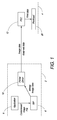
- FIG. 1 there is shown schematically a printing system having a specific architecture for implementing the method described in connection with the first aspect.
- a computer system 2 communicates with a printer 4 via a suitable communications link, such as a wired or wireless connection.
- the computer system 2 comprises a raster image processor (RIP) 6 which receives a compressed image file from a suitable application 8 generating images to be printed.
- the compressed image file may be in any suitable image file format, such as PDF, JPEG, TIFF, GIF etc or any suitable page description language, such as a PostScript, PDL etc.
- the RIP 6 processes the compressed image data and sends bitmap image data to a printer driver 10.
- the printer driver 10 sends the bitmap image data together with keep-wet pattern data ("keep-wet data") for each ink plane of a printhead 20 to a print engine controller chip (“PEC”) 12 of the printer 4. Determination of the appropriate keep-wet pattern data for each ink plane will be described in further detail below.
- the application 8 may send a compressed image file directly to the printer driver 10, which sends compressed image data to the PEC 12.
- the PEC 12 decompresses the compressed image data to generate bitmap image data.
- the printer driver 10 may send a pattern identifier for each ink plane to the PEC 12 instead of actual keep-wet pattern data.
- the PEC 12 retrieves keep-wet pattern data corresponding to each pattern identifier from a memory of the printer 4 (e.g. a memory in the PEC 12), which stores a plurality of different keep-wet pattern data, each being indexed with a respective pattern identifier.
- the printer driver 10 sends only image data to the PEC 12.
- the PEC 12 (rather than the printer driver 10) determines appropriate keep-wet pattern data for each ink plane and retrieves these data from a memory.
- the PEC 12 generates print data for each ink plane of the printhead 20.
- the printhead 20 has five ink planes, although it will be appreciated that the printhead may have any number of ink planes.
- the keep-wet data for each of the five ink planes, received from the printer driver 10, is loaded into a first writable memory 22 (e.g. RAM) of the PEC 12 while the image data is loaded into a second writable memory 24, which may be a same or different memory unit of the PEC.
- the image data is separated into the different ink planes and processed in the PEC to generate first print data for each ink plane.
- the first print data for each ink plane is merged (OR'd) with corresponding keep-wet data for that ink plane (by retrieving the corresponding keep-wet data from the first writable memory 22) to generate second print data.
- print data is sent to the printhead 20 for each ink plane.
- the second print data resulting from the merging step is usually processed further in the PEC 12 to generate third print data before being sent to the printhead 20. It will, of course be appreciated that Figure 2 represents a simplified scheme for PEC processing and that some processing steps for generating print data have been omitted for clarity.
- the keep-wet pattern data represents a pseudo random pattern of dots which is superimposed on the printed image.
- the keep-wet pattern ensures that each nozzle of the printhead 20 is fired within a predetermined period of time, which is generally less than the decap time of that nozzle.
- the keep-wet pattern therefore ensures that each nozzle of the printhead stays properly hydrated during a print job, even if the printed image does not demand firing of that nozzle and there has been no maintenance intervention.
- each unit cell of the keep-wet pattern for a particular ink channel may be comprised of a m x n rectangular cell 26, which is tiled over a page 27.
- the number of rows n (representing the height of the cell) may be in the range of 200 to 100,000 lines of print and the number of columns m (representing the width of the cell) may be in the range of 100 to 5,000 nozzles.
- the lines of print are schematically represented as lines 28, while the nozzles are schematically represented as arrows 29 (only two shown for clarity).
- unit cell 26 may have any suitable shape (e.g. hexagonal, triangular etc) or dimension. However, relatively larger cells 26 provide a greater degree of pseudo randomness in the keep-wet pattern and lower overall visibility.
- a different offset may be applied to the keep-wet pattern on sequential pages so that the same keep-wet pattern is not tiled across each printed page in a sequence.
- the offset helps to remove repetition artifacts which may be visible in collated documents e.g. a dot appearing at the same position at an edge of every page.
- the offset is typically applied by the PEC 12 before merging the keep-wet pattern data with the first print data.
- the offset may be a simple instruction to advance the keep-wet pattern by p row(s) and/or q column(s) for every printed page, where p ⁇ n and q ⁇ m.
- p and q are each independently integers of 1 to 50.
- a drawback of printing the keep-wet pattern is a loss of print quality and it is, therefore, important to ensure that the visibility of the keep-wet pattern is minimized as far as possible.
- the first aspect of the present invention enables the keep-wet pattern for each ink plane of the printhead to be tailored to a particular print job.
- the printer driver 10 determines a keep-wet pattern suitable for each ink plane based on one or more input parameters and sends appropriate keep-wet pattern data to the PEC 12.
- the printer driver 10 typically has an algorithm for determining the most appropriate combination of keep-wet patterns for the ink planes by weighting the various input parameters accordingly. As described above, in an alternative system architecture, determination of the keep-wet pattern data may be performed entirely by the PEC 12 in the printer 4.
- the position of the ink plane in the printhead determines, to a large extent, the local dehydrating environment of the ink plane and, therefore, the frequency of keep-wet ejections required.
- the ink plane furthest upstream in the printhead is in the most dehydrating environment as a result of the airflow experienced by the printhead and, therefore, requires a more frequent keep-wet pattern than the downstream ink planes. This is discussed in more detail below.
- the print speed is directly related to the speed of airflow experienced by the printhead. With higher print speeds, the speed of the airflow generated by the moving print media is higher and this has a greater dehydrating effect on the nozzles.
- the color of ink is an important factor in determining an appropriate keep-wet pattern.
- the keep-wet pattern is most visible with high luminance inks, such as black and least visible with low luminance inks, such as yellow. Therefore, a higher frequency keep-wet pattern is usually more tolerable in a yellow ink plane than a black ink plane. Indeed, yellow keep-wet patterns are virtually invisible, even at relatively high keep-wet frequencies.
- inks intrinsically have different dehydration characteristics than other inks and this is a fundamental criterion for determining an appropriate keep-wet pattern for a particular ink plane. For example, inks having a relatively high colorant loading tend to suffer more from dehydration effects than inks having a relatively low colorant loading. Of course, in a monochrome printhead, where all ink planes eject the same ink, the intrinsic dehydration characteristics of the ink will be the same in each ink plane of the printhead.
- Keep-wet patterns are usually less visible when printed on plain print media and more visible when printed on glossy print media.
- the length of the print job is an important parameter for determining an appropriate keep-wet pattern.
- the keep-wet pattern should be determined based on the greatest anticipated dehydrating environment, which will usually be at the end of the print run.
- Ambient humidity may be measured using an appropriate humidity sensor on the printer and feeding back ambient humidity data to the printer driver. If the printer is positioned in a relatively humid environment, then a less frequent keep-wet pattern will be required compared to a relatively dry environment.
- Ambient temperature may be measured using a temperature sensor on the printer and feeding back ambient temperature data to the printer driver. If the printer is positioned in a relatively cool environment, then a less frequent keep-wet pattern will be required compared to a relatively warm environment.
- the keep-wet dots should be coincident with the image, as far as possible, so that they have minimal effect on print quality. Likewise, printing high luminance (black) keep-wet dots on areas of low luminance in the image should be avoided as far as possible. Accordingly, the determination of the most appropriate keep-wet pattern for each ink plane may take into account the image data. For example, if the image contains regularly repeating blocks of color, then a keep-wet pattern coincident with these repeating blocks of color may be most appropriate.
- the ink planes of the printhead typically eject different keep-wet patterns. Visibility of the combined keep-wet patterns may be inadvertently increased if there are any optical interference effects (e.g. Moiré interference effects) between the various keep-wet patterns. Therefore, the selected keep-wet patterns for the ink planes of the printhead should preferably be orthogonal in the sense that they produce minimal optical interference effects when printed together on the print media. Usually, the keep-wet patterns are selected to minimize any dot-on-dot printing from the different keep-wet patterns.
- Each print job may have a minimum print quality threshold which is set by the end user. Although maximizing print quality is paramount, some end uses may have different print quality criteria to others. This, in turn, affects the keep-wet patterns available for use. In some circumstances, it may be necessary to change other print parameters (e.g. print speed or length of print job) so that the keep-wet pattern can be incorporated within acceptable print quality limits.
- print parameters e.g. print speed or length of print job
- keep-wet pattern for each ink plane of the printhead 4 may be tailored to provide an overall printed keep-wet pattern, which has minimum visibility.
- a printhead employed in connection with the present disclosure typically comprises a plurality of ink planes.
- Each ink plane comprises one or more nozzle rows, with each nozzle in one ink plane being supplied with the same ink.
- a Memjet ® printhead comprises a pair of nozzle rows per ink plane, which are supplied with the same ink - one nozzle row prints 'even' dots and the other nozzle row prints 'odd' dots to make up a line of print for one ink plane.
- the plurality of ink planes may be supplied with the same ink, all different inks, or at least one same ink and at least one different ink.
- all five ink planes may be supplied with the same ink to provide a monochrome printhead (e.g. CCCCC, MMMMM, YYYYY, KKKKK etc .).
- only some of the ink planes may be supplied with the same ink (e.g. CMYKK, CCMMY etc ).
- each ink plane may be supplied with a different ink (e.g. CMYK(IR) or CMYKS, where IR is an infrared ink and S is a spot color, such as khaki, orange, green, metallic inks etc ) .
- each ink plane of the printhead is positioned relatively upstream or downstream with respect to the media feed direction.
- the present inventors have found that the relative positioning of each ink plane in a fixed inkjet printhead has a marked effect on the local humidity of that ink plane relative to the other ink planes in the printhead during printing.
- the ink plane positioned furthest upstream with respect to the media feed direction is observed to be a in a relatively more dehydrating environment ( i.e. less humid) than other ink planes in the printhead.
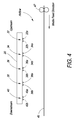
- FIG. 4 there is shown schematically a side view of the inkjet printhead 20 comprising five ink planes (32, 34, 36, 38 and 40), each comprising a pair of nozzle rows (32A & 32B, 34A & 34B, 36A & 36B, 38A & 38B and 40A & 40B).
- the ink planes are separated from each by a distance in the range of 50 to 100 microns.
- a print medium 45 is fed in a media feed direction (right to left as shown in Figure 4 ) by a media feed mechanism 47, which may take the form of a pair of opposed rollers gripping the print medium in a nip defined therebetween.
- the media feed direction therefore defines an upstream side and a downstream side of the printhead 20.
- the motion of the print medium 45 in the media feed direction generates an airflow in a corresponding direction, as shown in Figure 4 .
- the speed of this airflow depends on the speed of the print medium, and to some extent, the type of print medium. For example, a continuous web will tend to generate a higher airflow than printing onto discrete sheets of print media.
- the ink plane 32 furthest upstream in the printhead 20 is positioned in the relatively most dehydrating environment compared to the other ink planes 34, 36, 38 and 40.
- the ink plane 32 is most exposed to the airflow, whereas the downstream ink planes 34, 36, 38 and 40 enjoy a degree of shielding from this dehydrating airflow by virtue of a stream of ink droplets ejected from nozzle rows 32A and 32B.
- the printhead 20 It is desirable for the printhead 20 to eject the minimum required frequency of keep-wet drops in order to maintain each nozzle of the printhead sufficiently hydrated during a print job. Any keep-wet drops which are excess to requirements are not only wasteful of ink, but more importantly, reduce print quality unnecessarily.
- the minimum keep-wet frequency required for ink plane 32 will be higher than the minimum keep-wet frequency required for the other ink planes 34, 36, 38 and 40. This observation may be used in both monochrome and multicolor printheads to minimize the overall visibility of keep-wet patterns by ensuring only a minimum required keep-wet frequency for each ink plane.
- supplying a low luminance color, such as yellow, to the furthest upstream ink plane 32 advantageously minimizes the visibility of the relatively high frequency keep-wet pattern ejected from this ink plane.
- yellow has by far the lowest luminance compared to other colors.
- the nominal luminances of CMYK inks on white paper are as follows: C (30%), M (59%), Y (11%) and K (100%)). Therefore, by supplying yellow ink to the furthest upstream ink plane 32, the perceived visibility of the overall keep-wet pattern ejected by all color planes can be significantly reduced.
- the furthest upstream ink plane 32 is positioned in a locally most dehydrating environment of the printhead 20, because it does not benefit from any shielding from the airflow.
- a secondary factor determining local humidity of a particular ink plane is the number of neighboring ink planes.
- ink planes 34, 36 and 38 each have a pair of neighboring ink planes, whereas ink planes 32 and 40 only have one neighboring ink plane. Neighboring ink planes tend to increase the local humidity of an ink plane sandwiched therebetween.
- ink plane 40 positioned furthest downstream in printhead 20 is positioned in a relatively more dehydrating environment than ink planes 34, 36 and 38, but in a relatively less dehydrating environment than ink plane 32. Consequently, the relative minimum keep-wet frequencies of the ink planes for the printhead 20 may be in the order:
- ink planes 34, 36 and 40 are positioned in the least dehydrating local environment, it is advantageous to supply the highest luminance ink(s) (typically black) to these middle ink planes in order to minimize visibility of keep-wet patterns.
- an advantageous plumbing arrangement may be Y-K-M-K-C or Y-K-C-K-M, with yellow (Y) furthest upstream and black (K) occupying middle ink planes.
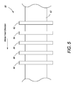
- Figure 5 shows schematically in plan view a high-speed web printer 50 comprised of five fixed inkjet printheads 52, 54, 56, 58 and 60, which are aligned with each other in a media feed direction.
- the printheads are spaced apart from each by a distance in the range of 3 to 20 cm.
- Each printhead is a monochrome printhead, which ejects a single color of ink from a plurality of ink planes.
- the five monochrome printheads 52, 54, 56, 58 and 60 may eject CMYK inks (e.g. CMYKK) or CMYKS inks.
- a web of print media 62 is fed past each of the printheads in the media feed direction as shown using a suitable media feed mechanism.
- This type of printer which is described in more detail in US 2012/0092403 (incorporated herein by reference), is capable of printing at very high speeds, such as speeds greater than 0.2 meters per second, greater than 0.5 meters per second, or greater than 1 meter per second.
- the printhead 52 positioned furthest upstream with respect to the media feed direction is in the relatively most dehydrating environment compared to the other printheads 54, 56, 58 and 60. Therefore, the printhead 52 generally requires a higher average keep-wet frequency than the other printheads. (Note that individual ink planes in each printhead may have different keep-wet frequencies, but the average minimum keep-wet frequency across all ink planes in printhead 52 is higher than the average minimum keep-wet frequency for the other printheads 54, 56, 58 and 60).
- printhead 52 with the lowest luminance ink (usually yellow) so that the keep-wet pattern ejected from printhead 52 has minimal visibility - the lower luminance of yellow ink effectively compensates for the higher average keep-wet frequency required in printhead 52.
- the printhead spacing in the printer 50 is of the order of centimeters, as opposed to the micron-scale separation of ink planes within the printhead 20, the local humidifying effects in the printer 50 will be less pronounced than those described above in connection with Figure 4 .
Landscapes
- Ink Jet (AREA)
Applications Claiming Priority (2)
| Application Number | Priority Date | Filing Date | Title |
|---|---|---|---|
| US201361858265P | 2013-07-25 | 2013-07-25 | |
| PCT/EP2014/064777 WO2015010911A1 (en) | 2013-07-25 | 2014-07-09 | Method of inkjet printing and maintaining nozzle hydration |
Publications (2)
| Publication Number | Publication Date |
|---|---|
| EP2983918A1 EP2983918A1 (en) | 2016-02-17 |
| EP2983918B1 true EP2983918B1 (en) | 2016-11-30 |
Family
ID=51211199
Family Applications (1)
| Application Number | Title | Priority Date | Filing Date |
|---|---|---|---|
| EP14741240.7A Active EP2983918B1 (en) | 2013-07-25 | 2014-07-09 | Method of inkjet printing and maintaining nozzle hydration |
Country Status (8)
| Country | Link |
|---|---|
| US (5) | US9469098B2 (enExample) |
| EP (1) | EP2983918B1 (enExample) |
| JP (1) | JP6386557B2 (enExample) |
| KR (1) | KR102194186B1 (enExample) |
| CN (1) | CN105246696B (enExample) |
| AU (1) | AU2014295345B2 (enExample) |
| TW (1) | TWI626168B (enExample) |
| WO (1) | WO2015010911A1 (enExample) |
Families Citing this family (10)
| Publication number | Priority date | Publication date | Assignee | Title |
|---|---|---|---|---|
| US9434156B2 (en) * | 2011-09-21 | 2016-09-06 | Memjet Technology Limited | Method of inkjet printing and maintaining nozzle hydration |
| TWI626168B (zh) * | 2013-07-25 | 2018-06-11 | 滿捷特科技公司 | 噴墨列印及保持噴嘴水合作用的方法 |
| JP6355412B2 (ja) * | 2014-04-30 | 2018-07-11 | キヤノン株式会社 | インクジェット記録装置およびインクジェット記録装置の制御方法 |
| WO2016169956A1 (en) | 2015-04-20 | 2016-10-27 | Eth Zurich | Print pattern generation on a substrate |
| US10451036B2 (en) * | 2017-05-05 | 2019-10-22 | General Electric Company | Adjustment factor for aerodynamic performance map |
| EP3738039A4 (en) * | 2018-01-08 | 2021-08-11 | Hewlett-Packard Development Company, L.P. | COLLECTIVE AWARENESS OF SUPPLIES |
| DE102018101295B4 (de) * | 2018-01-22 | 2020-10-08 | Canon Production Printing Holding B.V. | Verfahren und Vorrichtung zum Bedrucken eines Aufzeichnungsträgers mit einem Beschichtungsstoff und entsprechendes Drucksystem |
| EP3774351A4 (en) * | 2018-05-14 | 2021-12-01 | Hewlett-Packard Development Company, L.P. | PRINT HEAD AND PRINT HEAD MAINTENANCE |
| WO2019240823A1 (en) | 2018-06-15 | 2019-12-19 | Hewlett-Packard Development Company, L.P. | Method and apparatus for printhead maintenance |
| US20240399750A1 (en) | 2023-05-31 | 2024-12-05 | Memjet Technology Limited | Printing unit with aerosol extractors for overlapping printheads |
Family Cites Families (42)
| Publication number | Priority date | Publication date | Assignee | Title |
|---|---|---|---|---|
| US5668584A (en) * | 1992-05-01 | 1997-09-16 | Hewlett-Packard Company | Method of multiple zone heating of inkjet media using screen platen |
| JP3332569B2 (ja) * | 1994-04-26 | 2002-10-07 | キヤノン株式会社 | 液体噴射プリント装置およびプリント方法 |
| US6447095B1 (en) | 1994-05-19 | 2002-09-10 | Canon Kabushiki Kaisha | Discharge recovery method for ink jet apparatus using waterproof ink and ink jet apparatus employing the method |
| US6109716A (en) | 1997-03-28 | 2000-08-29 | Brother Kogyo Kabushiki Kaisha | Ink-jet printing apparatus having printed head driven by ink viscosity dependent drive pulse |
| DE60035145T2 (de) | 1999-04-08 | 2008-02-14 | Seiko Epson Corp. | Tintenstrahlaufzeichnungsgerät und Steuerverfahren für die Reinigung des eingebauten Aufzeichnungskopfes |
| JP3545325B2 (ja) * | 2000-09-12 | 2004-07-21 | シャープ株式会社 | インクジェット方式の画像形成装置および画像形成方法 |
| JP2002144599A (ja) | 2000-11-13 | 2002-05-21 | Canon Inc | インクジェト記録装置および予備吐出方法 |
| DE60229093D1 (de) * | 2001-08-29 | 2008-11-13 | Seiko Epson Corp | Flüssigkeitsstrahlvorrichtung und Verfahren zu deren Steuerung |
| EP1332886A1 (en) * | 2002-01-31 | 2003-08-06 | Hewlett Packard Company, a Delaware Corporation | Printer device and servicing routine |
| GB0205794D0 (en) | 2002-03-12 | 2002-04-24 | Montelius Lars G | Mems devices on a nanometer scale |
| US6598960B1 (en) | 2002-05-23 | 2003-07-29 | Eastman Kodak Company | Multi-layer thermal actuator with optimized heater length and method of operating same |
| US7018022B2 (en) | 2002-06-12 | 2006-03-28 | Sharp Kabushiki Kaisha | Inkjet printhead and inkjet image apparatus |
| JP2004090233A (ja) | 2002-08-29 | 2004-03-25 | Canon Inc | インクジェット記録装置 |
| US6817702B2 (en) | 2002-11-13 | 2004-11-16 | Eastman Kodak Company | Tapered multi-layer thermal actuator and method of operating same |
| JP4352915B2 (ja) * | 2004-01-30 | 2009-10-28 | セイコーエプソン株式会社 | 液滴吐出装置、液滴吐出装置の処理方法 |
| US7275805B2 (en) * | 2004-05-27 | 2007-10-02 | Silverbrook Research Pty Ltd | Printhead comprising different printhead modules |
| US7290852B2 (en) * | 2004-05-27 | 2007-11-06 | Silverbrook Research Pty Ltd | Printhead module having a dropped row |
| JP2006001051A (ja) * | 2004-06-15 | 2006-01-05 | Canon Inc | インクジェット記録方法およびインクジェット記録装置 |
| US7494215B2 (en) * | 2004-10-29 | 2009-02-24 | Hewlett-Packard Development Company, L.P. | Multiple chamber ink cartridge |
| KR100612022B1 (ko) * | 2004-11-04 | 2006-08-11 | 삼성전자주식회사 | 와이드 프린트헤드를 구비한 잉크젯 프린터의 인쇄방법 및장치 |
| JP4693648B2 (ja) * | 2005-03-23 | 2011-06-01 | キヤノンファインテック株式会社 | インクジェット印刷装置およびその予備吐出制御方法 |
| US7448729B2 (en) * | 2005-04-04 | 2008-11-11 | Silverbrook Research Pty Ltd | Inkjet printhead heater elements with thin or non-existent coatings |
| US7246876B2 (en) | 2005-04-04 | 2007-07-24 | Silverbrook Research Pty Ltd | Inkjet printhead for printing with low density keep-wet dots |
| CN101287606B (zh) * | 2006-03-03 | 2010-11-03 | 西尔弗布鲁克研究有限公司 | 脉冲阻尼射流结构 |
| JP2007268964A (ja) * | 2006-03-31 | 2007-10-18 | Fujifilm Corp | インクジェット記録方法及び装置 |
| US7719719B2 (en) * | 2006-09-18 | 2010-05-18 | Xerox Corporation | Sharpening a halftoned image |
| JP2008142972A (ja) * | 2006-12-07 | 2008-06-26 | Canon Inc | インクジェット記録装置、およびインクジェット記録方法 |
| JP4950859B2 (ja) * | 2006-12-08 | 2012-06-13 | キヤノン株式会社 | インクジェット記録装置 |
| JP4931573B2 (ja) * | 2006-12-20 | 2012-05-16 | 富士フイルム株式会社 | 画像形成方法及び装置 |
| JP2008265057A (ja) * | 2007-04-17 | 2008-11-06 | Fuji Xerox Co Ltd | 画像形成装置及びプログラム |
| JP4930391B2 (ja) * | 2008-01-29 | 2012-05-16 | ブラザー工業株式会社 | 記録装置 |
| EP2307001A1 (en) * | 2008-06-11 | 2011-04-13 | BioChemics, Inc. | Control of blood vessel physiology to treat skin disorders |
| JP5604790B2 (ja) * | 2009-02-04 | 2014-10-15 | セイコーエプソン株式会社 | 印刷方法及び印刷装置 |
| US20110025766A1 (en) * | 2009-07-31 | 2011-02-03 | Silverbrook Research Pty Ltd | Wide format printer with adjustable aerosol collection |
| JP5532946B2 (ja) * | 2010-01-18 | 2014-06-25 | セイコーエプソン株式会社 | 印刷装置における印刷条件設定方法 |
| US20120009240A1 (en) * | 2010-07-08 | 2012-01-12 | Joshua Stopek | Films for Delivery of a Therapeutic Agent |
| SG189040A1 (en) * | 2010-10-15 | 2013-05-31 | Zamtec Ltd | Multiple monochromatic print cartridge printing system and print alignment method |
| JP2012179776A (ja) * | 2011-03-01 | 2012-09-20 | Seiko Epson Corp | 印刷装置 |
| US9434156B2 (en) * | 2011-09-21 | 2016-09-06 | Memjet Technology Limited | Method of inkjet printing and maintaining nozzle hydration |
| JP5429322B2 (ja) * | 2012-05-01 | 2014-02-26 | ブラザー工業株式会社 | 液体吐出装置 |
| JP6023483B2 (ja) * | 2012-07-03 | 2016-11-09 | 理想科学工業株式会社 | 印刷装置 |
| TWI626168B (zh) * | 2013-07-25 | 2018-06-11 | 滿捷特科技公司 | 噴墨列印及保持噴嘴水合作用的方法 |
-
2014
- 2014-06-25 TW TW103121897A patent/TWI626168B/zh active
- 2014-07-09 WO PCT/EP2014/064777 patent/WO2015010911A1/en not_active Ceased
- 2014-07-09 KR KR1020167003168A patent/KR102194186B1/ko active Active
- 2014-07-09 CN CN201480030740.8A patent/CN105246696B/zh active Active
- 2014-07-09 JP JP2016528398A patent/JP6386557B2/ja active Active
- 2014-07-09 EP EP14741240.7A patent/EP2983918B1/en active Active
- 2014-07-09 AU AU2014295345A patent/AU2014295345B2/en active Active
- 2014-07-10 US US14/328,524 patent/US9469098B2/en active Active
- 2014-07-10 US US14/328,529 patent/US9944065B2/en active Active
- 2014-07-10 US US14/328,520 patent/US9545787B2/en active Active
-
2016
- 2016-12-09 US US15/374,980 patent/US10029458B2/en active Active
-
2018
- 2018-01-24 US US15/879,327 patent/US10377131B2/en active Active
Non-Patent Citations (1)
| Title |
|---|
| None * |
Also Published As
| Publication number | Publication date |
|---|---|
| US20150029247A1 (en) | 2015-01-29 |
| EP2983918A1 (en) | 2016-02-17 |
| CN105246696A (zh) | 2016-01-13 |
| US9545787B2 (en) | 2017-01-17 |
| US10377131B2 (en) | 2019-08-13 |
| AU2014295345A1 (en) | 2015-10-08 |
| TWI626168B (zh) | 2018-06-11 |
| WO2015010911A1 (en) | 2015-01-29 |
| AU2014295345B2 (en) | 2016-08-25 |
| US20170120581A1 (en) | 2017-05-04 |
| US20150360465A9 (en) | 2015-12-17 |
| US20150029264A1 (en) | 2015-01-29 |
| US20180147832A1 (en) | 2018-05-31 |
| KR20160034940A (ko) | 2016-03-30 |
| US20150029248A1 (en) | 2015-01-29 |
| TW201520067A (zh) | 2015-06-01 |
| US20150367629A9 (en) | 2015-12-24 |
| JP6386557B2 (ja) | 2018-09-05 |
| CN105246696B (zh) | 2016-11-16 |
| US10029458B2 (en) | 2018-07-24 |
| KR102194186B1 (ko) | 2020-12-23 |
| JP2016527107A (ja) | 2016-09-08 |
| US9469098B2 (en) | 2016-10-18 |
| US9944065B2 (en) | 2018-04-17 |
Similar Documents
| Publication | Publication Date | Title |
|---|---|---|
| US10377131B2 (en) | Method of multi-color pagewide printing with optimized nozzle hydration | |
| EP0623473B1 (en) | Increased print resolution in the carriage scan axis of an inkjet printer | |
| US8267506B2 (en) | Ink jet printer device and humidification method of ejection portion | |
| US20060092221A1 (en) | Printing method and apparatus for an ink-jet printer having a wide printhead | |
| US9004634B2 (en) | Inkjet printer | |
| JP2012148535A (ja) | 記録方法及び記録装置 | |
| EP1902848A2 (en) | Inkjet printer and printing method using the same | |
| US9434156B2 (en) | Method of inkjet printing and maintaining nozzle hydration | |
| US8845063B2 (en) | Printing apparatus and printing method | |
| US9162479B2 (en) | Inkjet printer having offset nozzle arrays | |
| US20110193905A1 (en) | Printing device | |
| KR20070121255A (ko) | 어레이형 멀티패스 잉크젯 프린터 및 그의 동작방법 | |
| EP1952993B1 (en) | Method of printing and printing system | |
| US11167563B2 (en) | Ink-jet recording apparatus, ink-jet recording method, and ink-jet recording program | |
| US9199464B2 (en) | Inkjet printer with offset ink nozzle array | |
| US11017277B2 (en) | Image processing apparatus, image processing method and storage medium, with correction amount for correcting line width in accordance with color of line | |
| JP2015024570A (ja) | 記録装置および記録方法 | |
| KR20080022004A (ko) | 잉크카트리지 및 화상형성장치 |
Legal Events
| Date | Code | Title | Description |
|---|---|---|---|
| PUAI | Public reference made under article 153(3) epc to a published international application that has entered the european phase |
Free format text: ORIGINAL CODE: 0009012 |
|
| 17P | Request for examination filed |
Effective date: 20151026 |
|
| AK | Designated contracting states |
Kind code of ref document: A1 Designated state(s): AL AT BE BG CH CY CZ DE DK EE ES FI FR GB GR HR HU IE IS IT LI LT LU LV MC MK MT NL NO PL PT RO RS SE SI SK SM TR |
|
| AX | Request for extension of the european patent |
Extension state: BA ME |
|
| GRAP | Despatch of communication of intention to grant a patent |
Free format text: ORIGINAL CODE: EPIDOSNIGR1 |
|
| DAX | Request for extension of the european patent (deleted) | ||
| INTG | Intention to grant announced |
Effective date: 20160901 |
|
| GRAS | Grant fee paid |
Free format text: ORIGINAL CODE: EPIDOSNIGR3 |
|
| GRAA | (expected) grant |
Free format text: ORIGINAL CODE: 0009210 |
|
| AK | Designated contracting states |
Kind code of ref document: B1 Designated state(s): AL AT BE BG CH CY CZ DE DK EE ES FI FR GB GR HR HU IE IS IT LI LT LU LV MC MK MT NL NO PL PT RO RS SE SI SK SM TR |
|
| REG | Reference to a national code |
Ref country code: CH Ref legal event code: EP Ref country code: GB Ref legal event code: FG4D |
|
| REG | Reference to a national code |
Ref country code: AT Ref legal event code: REF Ref document number: 849414 Country of ref document: AT Kind code of ref document: T Effective date: 20161215 |
|
| REG | Reference to a national code |
Ref country code: IE Ref legal event code: FG4D |
|
| REG | Reference to a national code |
Ref country code: DE Ref legal event code: R096 Ref document number: 602014005245 Country of ref document: DE |
|
| PG25 | Lapsed in a contracting state [announced via postgrant information from national office to epo] |
Ref country code: LV Free format text: LAPSE BECAUSE OF FAILURE TO SUBMIT A TRANSLATION OF THE DESCRIPTION OR TO PAY THE FEE WITHIN THE PRESCRIBED TIME-LIMIT Effective date: 20161130 |
|
| REG | Reference to a national code |
Ref country code: LT Ref legal event code: MG4D |
|
| REG | Reference to a national code |
Ref country code: NL Ref legal event code: MP Effective date: 20161130 |
|
| REG | Reference to a national code |
Ref country code: AT Ref legal event code: MK05 Ref document number: 849414 Country of ref document: AT Kind code of ref document: T Effective date: 20161130 |
|
| PG25 | Lapsed in a contracting state [announced via postgrant information from national office to epo] |
Ref country code: SE Free format text: LAPSE BECAUSE OF FAILURE TO SUBMIT A TRANSLATION OF THE DESCRIPTION OR TO PAY THE FEE WITHIN THE PRESCRIBED TIME-LIMIT Effective date: 20161130 Ref country code: NO Free format text: LAPSE BECAUSE OF FAILURE TO SUBMIT A TRANSLATION OF THE DESCRIPTION OR TO PAY THE FEE WITHIN THE PRESCRIBED TIME-LIMIT Effective date: 20170228 Ref country code: GR Free format text: LAPSE BECAUSE OF FAILURE TO SUBMIT A TRANSLATION OF THE DESCRIPTION OR TO PAY THE FEE WITHIN THE PRESCRIBED TIME-LIMIT Effective date: 20170301 Ref country code: LT Free format text: LAPSE BECAUSE OF FAILURE TO SUBMIT A TRANSLATION OF THE DESCRIPTION OR TO PAY THE FEE WITHIN THE PRESCRIBED TIME-LIMIT Effective date: 20161130 |
|
| PG25 | Lapsed in a contracting state [announced via postgrant information from national office to epo] |
Ref country code: ES Free format text: LAPSE BECAUSE OF FAILURE TO SUBMIT A TRANSLATION OF THE DESCRIPTION OR TO PAY THE FEE WITHIN THE PRESCRIBED TIME-LIMIT Effective date: 20161130 Ref country code: RS Free format text: LAPSE BECAUSE OF FAILURE TO SUBMIT A TRANSLATION OF THE DESCRIPTION OR TO PAY THE FEE WITHIN THE PRESCRIBED TIME-LIMIT Effective date: 20161130 Ref country code: PT Free format text: LAPSE BECAUSE OF FAILURE TO SUBMIT A TRANSLATION OF THE DESCRIPTION OR TO PAY THE FEE WITHIN THE PRESCRIBED TIME-LIMIT Effective date: 20170330 Ref country code: AT Free format text: LAPSE BECAUSE OF FAILURE TO SUBMIT A TRANSLATION OF THE DESCRIPTION OR TO PAY THE FEE WITHIN THE PRESCRIBED TIME-LIMIT Effective date: 20161130 Ref country code: PL Free format text: LAPSE BECAUSE OF FAILURE TO SUBMIT A TRANSLATION OF THE DESCRIPTION OR TO PAY THE FEE WITHIN THE PRESCRIBED TIME-LIMIT Effective date: 20161130 Ref country code: FI Free format text: LAPSE BECAUSE OF FAILURE TO SUBMIT A TRANSLATION OF THE DESCRIPTION OR TO PAY THE FEE WITHIN THE PRESCRIBED TIME-LIMIT Effective date: 20161130 Ref country code: HR Free format text: LAPSE BECAUSE OF FAILURE TO SUBMIT A TRANSLATION OF THE DESCRIPTION OR TO PAY THE FEE WITHIN THE PRESCRIBED TIME-LIMIT Effective date: 20161130 |
|
| PG25 | Lapsed in a contracting state [announced via postgrant information from national office to epo] |
Ref country code: NL Free format text: LAPSE BECAUSE OF FAILURE TO SUBMIT A TRANSLATION OF THE DESCRIPTION OR TO PAY THE FEE WITHIN THE PRESCRIBED TIME-LIMIT Effective date: 20161130 |
|
| REG | Reference to a national code |
Ref country code: FR Ref legal event code: PLFP Year of fee payment: 4 |
|
| PG25 | Lapsed in a contracting state [announced via postgrant information from national office to epo] |
Ref country code: RO Free format text: LAPSE BECAUSE OF FAILURE TO SUBMIT A TRANSLATION OF THE DESCRIPTION OR TO PAY THE FEE WITHIN THE PRESCRIBED TIME-LIMIT Effective date: 20161130 Ref country code: EE Free format text: LAPSE BECAUSE OF FAILURE TO SUBMIT A TRANSLATION OF THE DESCRIPTION OR TO PAY THE FEE WITHIN THE PRESCRIBED TIME-LIMIT Effective date: 20161130 Ref country code: SK Free format text: LAPSE BECAUSE OF FAILURE TO SUBMIT A TRANSLATION OF THE DESCRIPTION OR TO PAY THE FEE WITHIN THE PRESCRIBED TIME-LIMIT Effective date: 20161130 Ref country code: CZ Free format text: LAPSE BECAUSE OF FAILURE TO SUBMIT A TRANSLATION OF THE DESCRIPTION OR TO PAY THE FEE WITHIN THE PRESCRIBED TIME-LIMIT Effective date: 20161130 Ref country code: DK Free format text: LAPSE BECAUSE OF FAILURE TO SUBMIT A TRANSLATION OF THE DESCRIPTION OR TO PAY THE FEE WITHIN THE PRESCRIBED TIME-LIMIT Effective date: 20161130 |
|
| PG25 | Lapsed in a contracting state [announced via postgrant information from national office to epo] |
Ref country code: BG Free format text: LAPSE BECAUSE OF FAILURE TO SUBMIT A TRANSLATION OF THE DESCRIPTION OR TO PAY THE FEE WITHIN THE PRESCRIBED TIME-LIMIT Effective date: 20170228 Ref country code: IT Free format text: LAPSE BECAUSE OF FAILURE TO SUBMIT A TRANSLATION OF THE DESCRIPTION OR TO PAY THE FEE WITHIN THE PRESCRIBED TIME-LIMIT Effective date: 20161130 Ref country code: BE Free format text: LAPSE BECAUSE OF FAILURE TO SUBMIT A TRANSLATION OF THE DESCRIPTION OR TO PAY THE FEE WITHIN THE PRESCRIBED TIME-LIMIT Effective date: 20161130 Ref country code: SM Free format text: LAPSE BECAUSE OF FAILURE TO SUBMIT A TRANSLATION OF THE DESCRIPTION OR TO PAY THE FEE WITHIN THE PRESCRIBED TIME-LIMIT Effective date: 20161130 |
|
| REG | Reference to a national code |
Ref country code: DE Ref legal event code: R097 Ref document number: 602014005245 Country of ref document: DE |
|
| PLBE | No opposition filed within time limit |
Free format text: ORIGINAL CODE: 0009261 |
|
| STAA | Information on the status of an ep patent application or granted ep patent |
Free format text: STATUS: NO OPPOSITION FILED WITHIN TIME LIMIT |
|
| 26N | No opposition filed |
Effective date: 20170831 |
|
| PG25 | Lapsed in a contracting state [announced via postgrant information from national office to epo] |
Ref country code: SI Free format text: LAPSE BECAUSE OF FAILURE TO SUBMIT A TRANSLATION OF THE DESCRIPTION OR TO PAY THE FEE WITHIN THE PRESCRIBED TIME-LIMIT Effective date: 20161130 |
|
| REG | Reference to a national code |
Ref country code: CH Ref legal event code: PL |
|
| PG25 | Lapsed in a contracting state [announced via postgrant information from national office to epo] |
Ref country code: LI Free format text: LAPSE BECAUSE OF NON-PAYMENT OF DUE FEES Effective date: 20170731 Ref country code: CH Free format text: LAPSE BECAUSE OF NON-PAYMENT OF DUE FEES Effective date: 20170731 |
|
| PG25 | Lapsed in a contracting state [announced via postgrant information from national office to epo] |
Ref country code: LU Free format text: LAPSE BECAUSE OF NON-PAYMENT OF DUE FEES Effective date: 20170709 |
|
| REG | Reference to a national code |
Ref country code: FR Ref legal event code: PLFP Year of fee payment: 5 |
|
| PG25 | Lapsed in a contracting state [announced via postgrant information from national office to epo] |
Ref country code: MT Free format text: LAPSE BECAUSE OF NON-PAYMENT OF DUE FEES Effective date: 20170709 |
|
| PG25 | Lapsed in a contracting state [announced via postgrant information from national office to epo] |
Ref country code: HU Free format text: LAPSE BECAUSE OF FAILURE TO SUBMIT A TRANSLATION OF THE DESCRIPTION OR TO PAY THE FEE WITHIN THE PRESCRIBED TIME-LIMIT; INVALID AB INITIO Effective date: 20140709 Ref country code: MC Free format text: LAPSE BECAUSE OF FAILURE TO SUBMIT A TRANSLATION OF THE DESCRIPTION OR TO PAY THE FEE WITHIN THE PRESCRIBED TIME-LIMIT Effective date: 20161130 |
|
| PG25 | Lapsed in a contracting state [announced via postgrant information from national office to epo] |
Ref country code: CY Free format text: LAPSE BECAUSE OF FAILURE TO SUBMIT A TRANSLATION OF THE DESCRIPTION OR TO PAY THE FEE WITHIN THE PRESCRIBED TIME-LIMIT Effective date: 20161130 |
|
| PG25 | Lapsed in a contracting state [announced via postgrant information from national office to epo] |
Ref country code: MK Free format text: LAPSE BECAUSE OF FAILURE TO SUBMIT A TRANSLATION OF THE DESCRIPTION OR TO PAY THE FEE WITHIN THE PRESCRIBED TIME-LIMIT Effective date: 20161130 |
|
| PG25 | Lapsed in a contracting state [announced via postgrant information from national office to epo] |
Ref country code: TR Free format text: LAPSE BECAUSE OF FAILURE TO SUBMIT A TRANSLATION OF THE DESCRIPTION OR TO PAY THE FEE WITHIN THE PRESCRIBED TIME-LIMIT Effective date: 20161130 |
|
| PG25 | Lapsed in a contracting state [announced via postgrant information from national office to epo] |
Ref country code: AL Free format text: LAPSE BECAUSE OF FAILURE TO SUBMIT A TRANSLATION OF THE DESCRIPTION OR TO PAY THE FEE WITHIN THE PRESCRIBED TIME-LIMIT Effective date: 20161130 Ref country code: IS Free format text: LAPSE BECAUSE OF FAILURE TO SUBMIT A TRANSLATION OF THE DESCRIPTION OR TO PAY THE FEE WITHIN THE PRESCRIBED TIME-LIMIT Effective date: 20170330 |
|
| PGFP | Annual fee paid to national office [announced via postgrant information from national office to epo] |
Ref country code: IE Payment date: 20210727 Year of fee payment: 8 |
|
| P01 | Opt-out of the competence of the unified patent court (upc) registered |
Effective date: 20230420 |
|
| PG25 | Lapsed in a contracting state [announced via postgrant information from national office to epo] |
Ref country code: IE Free format text: LAPSE BECAUSE OF NON-PAYMENT OF DUE FEES Effective date: 20220709 |
|
| PGFP | Annual fee paid to national office [announced via postgrant information from national office to epo] |
Ref country code: DE Payment date: 20250729 Year of fee payment: 12 |
|
| PGFP | Annual fee paid to national office [announced via postgrant information from national office to epo] |
Ref country code: GB Payment date: 20250728 Year of fee payment: 12 |
|
| PGFP | Annual fee paid to national office [announced via postgrant information from national office to epo] |
Ref country code: FR Payment date: 20250725 Year of fee payment: 12 |