EP2980514A1 - Method for the low-temperature decomposition of air and air separation plant - Google Patents
Method for the low-temperature decomposition of air and air separation plant Download PDFInfo
- Publication number
- EP2980514A1 EP2980514A1 EP14002683.2A EP14002683A EP2980514A1 EP 2980514 A1 EP2980514 A1 EP 2980514A1 EP 14002683 A EP14002683 A EP 14002683A EP 2980514 A1 EP2980514 A1 EP 2980514A1
- Authority
- EP
- European Patent Office
- Prior art keywords
- pressure level
- air
- pressure
- heat exchanger
- turbine
- Prior art date
- Legal status (The legal status is an assumption and is not a legal conclusion. Google has not performed a legal analysis and makes no representation as to the accuracy of the status listed.)
- Withdrawn
Links
- 238000000926 separation method Methods 0.000 title claims abstract description 60
- 238000000034 method Methods 0.000 title claims abstract description 56
- 238000000354 decomposition reaction Methods 0.000 title 1
- 239000007788 liquid Substances 0.000 claims abstract description 49
- 238000004821 distillation Methods 0.000 claims abstract description 24
- 239000012530 fluid Substances 0.000 claims description 19
- 238000007789 sealing Methods 0.000 claims description 11
- 230000002040 relaxant effect Effects 0.000 claims description 4
- 238000007906 compression Methods 0.000 description 25
- 230000006835 compression Effects 0.000 description 23
- 239000000047 product Substances 0.000 description 23
- IJGRMHOSHXDMSA-UHFFFAOYSA-N Atomic nitrogen Chemical compound N#N IJGRMHOSHXDMSA-UHFFFAOYSA-N 0.000 description 18
- 238000001816 cooling Methods 0.000 description 11
- 229910052757 nitrogen Inorganic materials 0.000 description 9
- XKRFYHLGVUSROY-UHFFFAOYSA-N Argon Chemical compound [Ar] XKRFYHLGVUSROY-UHFFFAOYSA-N 0.000 description 8
- MYMOFIZGZYHOMD-UHFFFAOYSA-N Dioxygen Chemical compound O=O MYMOFIZGZYHOMD-UHFFFAOYSA-N 0.000 description 8
- QVGXLLKOCUKJST-UHFFFAOYSA-N atomic oxygen Chemical compound [O] QVGXLLKOCUKJST-UHFFFAOYSA-N 0.000 description 5
- 239000001301 oxygen Substances 0.000 description 5
- 229910052760 oxygen Inorganic materials 0.000 description 5
- 229910052786 argon Inorganic materials 0.000 description 4
- 239000000498 cooling water Substances 0.000 description 4
- 238000004140 cleaning Methods 0.000 description 3
- 238000004519 manufacturing process Methods 0.000 description 3
- CURLTUGMZLYLDI-UHFFFAOYSA-N Carbon dioxide Chemical compound O=C=O CURLTUGMZLYLDI-UHFFFAOYSA-N 0.000 description 2
- 238000004887 air purification Methods 0.000 description 2
- 238000005056 compaction Methods 0.000 description 2
- 238000010586 diagram Methods 0.000 description 2
- 230000002349 favourable effect Effects 0.000 description 2
- 238000010438 heat treatment Methods 0.000 description 2
- 239000000543 intermediate Substances 0.000 description 2
- 238000011144 upstream manufacturing Methods 0.000 description 2
- 230000000712 assembly Effects 0.000 description 1
- 238000000429 assembly Methods 0.000 description 1
- 239000003990 capacitor Substances 0.000 description 1
- 229910002092 carbon dioxide Inorganic materials 0.000 description 1
- 239000001569 carbon dioxide Substances 0.000 description 1
- 230000007423 decrease Effects 0.000 description 1
- 230000001419 dependent effect Effects 0.000 description 1
- 230000000694 effects Effects 0.000 description 1
- 239000007789 gas Substances 0.000 description 1
- 239000013529 heat transfer fluid Substances 0.000 description 1
- 229910052743 krypton Inorganic materials 0.000 description 1
- DNNSSWSSYDEUBZ-UHFFFAOYSA-N krypton atom Chemical compound [Kr] DNNSSWSSYDEUBZ-UHFFFAOYSA-N 0.000 description 1
- 239000012263 liquid product Substances 0.000 description 1
- DOTMOQHOJINYBL-UHFFFAOYSA-N molecular nitrogen;molecular oxygen Chemical compound N#N.O=O DOTMOQHOJINYBL-UHFFFAOYSA-N 0.000 description 1
- 230000007935 neutral effect Effects 0.000 description 1
- 229910052756 noble gas Inorganic materials 0.000 description 1
- 150000002835 noble gases Chemical class 0.000 description 1
- 238000011084 recovery Methods 0.000 description 1
- 238000005057 refrigeration Methods 0.000 description 1
- 230000007704 transition Effects 0.000 description 1
- 238000009834 vaporization Methods 0.000 description 1
- 230000008016 vaporization Effects 0.000 description 1
- XLYOFNOQVPJJNP-UHFFFAOYSA-N water Substances O XLYOFNOQVPJJNP-UHFFFAOYSA-N 0.000 description 1
- 229910052724 xenon Inorganic materials 0.000 description 1
- FHNFHKCVQCLJFQ-UHFFFAOYSA-N xenon atom Chemical compound [Xe] FHNFHKCVQCLJFQ-UHFFFAOYSA-N 0.000 description 1
Images
Classifications
-
- F—MECHANICAL ENGINEERING; LIGHTING; HEATING; WEAPONS; BLASTING
- F25—REFRIGERATION OR COOLING; COMBINED HEATING AND REFRIGERATION SYSTEMS; HEAT PUMP SYSTEMS; MANUFACTURE OR STORAGE OF ICE; LIQUEFACTION SOLIDIFICATION OF GASES
- F25J—LIQUEFACTION, SOLIDIFICATION OR SEPARATION OF GASES OR GASEOUS OR LIQUEFIED GASEOUS MIXTURES BY PRESSURE AND COLD TREATMENT OR BY BRINGING THEM INTO THE SUPERCRITICAL STATE
- F25J3/00—Processes or apparatus for separating the constituents of gaseous or liquefied gaseous mixtures involving the use of liquefaction or solidification
- F25J3/02—Processes or apparatus for separating the constituents of gaseous or liquefied gaseous mixtures involving the use of liquefaction or solidification by rectification, i.e. by continuous interchange of heat and material between a vapour stream and a liquid stream
- F25J3/04—Processes or apparatus for separating the constituents of gaseous or liquefied gaseous mixtures involving the use of liquefaction or solidification by rectification, i.e. by continuous interchange of heat and material between a vapour stream and a liquid stream for air
- F25J3/04406—Processes or apparatus for separating the constituents of gaseous or liquefied gaseous mixtures involving the use of liquefaction or solidification by rectification, i.e. by continuous interchange of heat and material between a vapour stream and a liquid stream for air using a dual pressure main column system
- F25J3/04412—Processes or apparatus for separating the constituents of gaseous or liquefied gaseous mixtures involving the use of liquefaction or solidification by rectification, i.e. by continuous interchange of heat and material between a vapour stream and a liquid stream for air using a dual pressure main column system in a classical double column flowsheet, i.e. with thermal coupling by a main reboiler-condenser in the bottom of low pressure respectively top of high pressure column
-
- F—MECHANICAL ENGINEERING; LIGHTING; HEATING; WEAPONS; BLASTING
- F25—REFRIGERATION OR COOLING; COMBINED HEATING AND REFRIGERATION SYSTEMS; HEAT PUMP SYSTEMS; MANUFACTURE OR STORAGE OF ICE; LIQUEFACTION SOLIDIFICATION OF GASES
- F25J—LIQUEFACTION, SOLIDIFICATION OR SEPARATION OF GASES OR GASEOUS OR LIQUEFIED GASEOUS MIXTURES BY PRESSURE AND COLD TREATMENT OR BY BRINGING THEM INTO THE SUPERCRITICAL STATE
- F25J3/00—Processes or apparatus for separating the constituents of gaseous or liquefied gaseous mixtures involving the use of liquefaction or solidification
- F25J3/02—Processes or apparatus for separating the constituents of gaseous or liquefied gaseous mixtures involving the use of liquefaction or solidification by rectification, i.e. by continuous interchange of heat and material between a vapour stream and a liquid stream
- F25J3/04—Processes or apparatus for separating the constituents of gaseous or liquefied gaseous mixtures involving the use of liquefaction or solidification by rectification, i.e. by continuous interchange of heat and material between a vapour stream and a liquid stream for air
- F25J3/04006—Providing pressurised feed air or process streams within or from the air fractionation unit
- F25J3/04012—Providing pressurised feed air or process streams within or from the air fractionation unit by compression of warm gaseous streams; details of intake or interstage cooling
- F25J3/04018—Providing pressurised feed air or process streams within or from the air fractionation unit by compression of warm gaseous streams; details of intake or interstage cooling of main feed air
-
- F—MECHANICAL ENGINEERING; LIGHTING; HEATING; WEAPONS; BLASTING
- F25—REFRIGERATION OR COOLING; COMBINED HEATING AND REFRIGERATION SYSTEMS; HEAT PUMP SYSTEMS; MANUFACTURE OR STORAGE OF ICE; LIQUEFACTION SOLIDIFICATION OF GASES
- F25J—LIQUEFACTION, SOLIDIFICATION OR SEPARATION OF GASES OR GASEOUS OR LIQUEFIED GASEOUS MIXTURES BY PRESSURE AND COLD TREATMENT OR BY BRINGING THEM INTO THE SUPERCRITICAL STATE
- F25J3/00—Processes or apparatus for separating the constituents of gaseous or liquefied gaseous mixtures involving the use of liquefaction or solidification
- F25J3/02—Processes or apparatus for separating the constituents of gaseous or liquefied gaseous mixtures involving the use of liquefaction or solidification by rectification, i.e. by continuous interchange of heat and material between a vapour stream and a liquid stream
- F25J3/04—Processes or apparatus for separating the constituents of gaseous or liquefied gaseous mixtures involving the use of liquefaction or solidification by rectification, i.e. by continuous interchange of heat and material between a vapour stream and a liquid stream for air
- F25J3/04006—Providing pressurised feed air or process streams within or from the air fractionation unit
- F25J3/04012—Providing pressurised feed air or process streams within or from the air fractionation unit by compression of warm gaseous streams; details of intake or interstage cooling
- F25J3/04024—Providing pressurised feed air or process streams within or from the air fractionation unit by compression of warm gaseous streams; details of intake or interstage cooling of purified feed air, so-called boosted air
-
- F—MECHANICAL ENGINEERING; LIGHTING; HEATING; WEAPONS; BLASTING
- F25—REFRIGERATION OR COOLING; COMBINED HEATING AND REFRIGERATION SYSTEMS; HEAT PUMP SYSTEMS; MANUFACTURE OR STORAGE OF ICE; LIQUEFACTION SOLIDIFICATION OF GASES
- F25J—LIQUEFACTION, SOLIDIFICATION OR SEPARATION OF GASES OR GASEOUS OR LIQUEFIED GASEOUS MIXTURES BY PRESSURE AND COLD TREATMENT OR BY BRINGING THEM INTO THE SUPERCRITICAL STATE
- F25J3/00—Processes or apparatus for separating the constituents of gaseous or liquefied gaseous mixtures involving the use of liquefaction or solidification
- F25J3/02—Processes or apparatus for separating the constituents of gaseous or liquefied gaseous mixtures involving the use of liquefaction or solidification by rectification, i.e. by continuous interchange of heat and material between a vapour stream and a liquid stream
- F25J3/04—Processes or apparatus for separating the constituents of gaseous or liquefied gaseous mixtures involving the use of liquefaction or solidification by rectification, i.e. by continuous interchange of heat and material between a vapour stream and a liquid stream for air
- F25J3/04006—Providing pressurised feed air or process streams within or from the air fractionation unit
- F25J3/04048—Providing pressurised feed air or process streams within or from the air fractionation unit by compression of cold gaseous streams, e.g. intermediate or oxygen enriched (waste) streams
- F25J3/04054—Providing pressurised feed air or process streams within or from the air fractionation unit by compression of cold gaseous streams, e.g. intermediate or oxygen enriched (waste) streams of air
-
- F—MECHANICAL ENGINEERING; LIGHTING; HEATING; WEAPONS; BLASTING
- F25—REFRIGERATION OR COOLING; COMBINED HEATING AND REFRIGERATION SYSTEMS; HEAT PUMP SYSTEMS; MANUFACTURE OR STORAGE OF ICE; LIQUEFACTION SOLIDIFICATION OF GASES
- F25J—LIQUEFACTION, SOLIDIFICATION OR SEPARATION OF GASES OR GASEOUS OR LIQUEFIED GASEOUS MIXTURES BY PRESSURE AND COLD TREATMENT OR BY BRINGING THEM INTO THE SUPERCRITICAL STATE
- F25J3/00—Processes or apparatus for separating the constituents of gaseous or liquefied gaseous mixtures involving the use of liquefaction or solidification
- F25J3/02—Processes or apparatus for separating the constituents of gaseous or liquefied gaseous mixtures involving the use of liquefaction or solidification by rectification, i.e. by continuous interchange of heat and material between a vapour stream and a liquid stream
- F25J3/04—Processes or apparatus for separating the constituents of gaseous or liquefied gaseous mixtures involving the use of liquefaction or solidification by rectification, i.e. by continuous interchange of heat and material between a vapour stream and a liquid stream for air
- F25J3/04006—Providing pressurised feed air or process streams within or from the air fractionation unit
- F25J3/04078—Providing pressurised feed air or process streams within or from the air fractionation unit providing pressurized products by liquid compression and vaporisation with cold recovery, i.e. so-called internal compression
- F25J3/04084—Providing pressurised feed air or process streams within or from the air fractionation unit providing pressurized products by liquid compression and vaporisation with cold recovery, i.e. so-called internal compression of nitrogen
-
- F—MECHANICAL ENGINEERING; LIGHTING; HEATING; WEAPONS; BLASTING
- F25—REFRIGERATION OR COOLING; COMBINED HEATING AND REFRIGERATION SYSTEMS; HEAT PUMP SYSTEMS; MANUFACTURE OR STORAGE OF ICE; LIQUEFACTION SOLIDIFICATION OF GASES
- F25J—LIQUEFACTION, SOLIDIFICATION OR SEPARATION OF GASES OR GASEOUS OR LIQUEFIED GASEOUS MIXTURES BY PRESSURE AND COLD TREATMENT OR BY BRINGING THEM INTO THE SUPERCRITICAL STATE
- F25J3/00—Processes or apparatus for separating the constituents of gaseous or liquefied gaseous mixtures involving the use of liquefaction or solidification
- F25J3/02—Processes or apparatus for separating the constituents of gaseous or liquefied gaseous mixtures involving the use of liquefaction or solidification by rectification, i.e. by continuous interchange of heat and material between a vapour stream and a liquid stream
- F25J3/04—Processes or apparatus for separating the constituents of gaseous or liquefied gaseous mixtures involving the use of liquefaction or solidification by rectification, i.e. by continuous interchange of heat and material between a vapour stream and a liquid stream for air
- F25J3/04006—Providing pressurised feed air or process streams within or from the air fractionation unit
- F25J3/04078—Providing pressurised feed air or process streams within or from the air fractionation unit providing pressurized products by liquid compression and vaporisation with cold recovery, i.e. so-called internal compression
- F25J3/0409—Providing pressurised feed air or process streams within or from the air fractionation unit providing pressurized products by liquid compression and vaporisation with cold recovery, i.e. so-called internal compression of oxygen
-
- F—MECHANICAL ENGINEERING; LIGHTING; HEATING; WEAPONS; BLASTING
- F25—REFRIGERATION OR COOLING; COMBINED HEATING AND REFRIGERATION SYSTEMS; HEAT PUMP SYSTEMS; MANUFACTURE OR STORAGE OF ICE; LIQUEFACTION SOLIDIFICATION OF GASES
- F25J—LIQUEFACTION, SOLIDIFICATION OR SEPARATION OF GASES OR GASEOUS OR LIQUEFIED GASEOUS MIXTURES BY PRESSURE AND COLD TREATMENT OR BY BRINGING THEM INTO THE SUPERCRITICAL STATE
- F25J3/00—Processes or apparatus for separating the constituents of gaseous or liquefied gaseous mixtures involving the use of liquefaction or solidification
- F25J3/02—Processes or apparatus for separating the constituents of gaseous or liquefied gaseous mixtures involving the use of liquefaction or solidification by rectification, i.e. by continuous interchange of heat and material between a vapour stream and a liquid stream
- F25J3/04—Processes or apparatus for separating the constituents of gaseous or liquefied gaseous mixtures involving the use of liquefaction or solidification by rectification, i.e. by continuous interchange of heat and material between a vapour stream and a liquid stream for air
- F25J3/04006—Providing pressurised feed air or process streams within or from the air fractionation unit
- F25J3/04109—Arrangements of compressors and /or their drivers
- F25J3/04115—Arrangements of compressors and /or their drivers characterised by the type of prime driver, e.g. hot gas expander
- F25J3/04121—Steam turbine as the prime mechanical driver
-
- F—MECHANICAL ENGINEERING; LIGHTING; HEATING; WEAPONS; BLASTING
- F25—REFRIGERATION OR COOLING; COMBINED HEATING AND REFRIGERATION SYSTEMS; HEAT PUMP SYSTEMS; MANUFACTURE OR STORAGE OF ICE; LIQUEFACTION SOLIDIFICATION OF GASES
- F25J—LIQUEFACTION, SOLIDIFICATION OR SEPARATION OF GASES OR GASEOUS OR LIQUEFIED GASEOUS MIXTURES BY PRESSURE AND COLD TREATMENT OR BY BRINGING THEM INTO THE SUPERCRITICAL STATE
- F25J3/00—Processes or apparatus for separating the constituents of gaseous or liquefied gaseous mixtures involving the use of liquefaction or solidification
- F25J3/02—Processes or apparatus for separating the constituents of gaseous or liquefied gaseous mixtures involving the use of liquefaction or solidification by rectification, i.e. by continuous interchange of heat and material between a vapour stream and a liquid stream
- F25J3/04—Processes or apparatus for separating the constituents of gaseous or liquefied gaseous mixtures involving the use of liquefaction or solidification by rectification, i.e. by continuous interchange of heat and material between a vapour stream and a liquid stream for air
- F25J3/04006—Providing pressurised feed air or process streams within or from the air fractionation unit
- F25J3/04109—Arrangements of compressors and /or their drivers
- F25J3/04145—Mechanically coupling of different compressors of the air fractionation process to the same driver(s)
-
- F—MECHANICAL ENGINEERING; LIGHTING; HEATING; WEAPONS; BLASTING
- F25—REFRIGERATION OR COOLING; COMBINED HEATING AND REFRIGERATION SYSTEMS; HEAT PUMP SYSTEMS; MANUFACTURE OR STORAGE OF ICE; LIQUEFACTION SOLIDIFICATION OF GASES
- F25J—LIQUEFACTION, SOLIDIFICATION OR SEPARATION OF GASES OR GASEOUS OR LIQUEFIED GASEOUS MIXTURES BY PRESSURE AND COLD TREATMENT OR BY BRINGING THEM INTO THE SUPERCRITICAL STATE
- F25J3/00—Processes or apparatus for separating the constituents of gaseous or liquefied gaseous mixtures involving the use of liquefaction or solidification
- F25J3/02—Processes or apparatus for separating the constituents of gaseous or liquefied gaseous mixtures involving the use of liquefaction or solidification by rectification, i.e. by continuous interchange of heat and material between a vapour stream and a liquid stream
- F25J3/04—Processes or apparatus for separating the constituents of gaseous or liquefied gaseous mixtures involving the use of liquefaction or solidification by rectification, i.e. by continuous interchange of heat and material between a vapour stream and a liquid stream for air
- F25J3/04151—Purification and (pre-)cooling of the feed air; recuperative heat-exchange with product streams
- F25J3/04163—Hot end purification of the feed air
- F25J3/04169—Hot end purification of the feed air by adsorption of the impurities
- F25J3/04175—Hot end purification of the feed air by adsorption of the impurities at a pressure of substantially more than the highest pressure column
-
- F—MECHANICAL ENGINEERING; LIGHTING; HEATING; WEAPONS; BLASTING
- F25—REFRIGERATION OR COOLING; COMBINED HEATING AND REFRIGERATION SYSTEMS; HEAT PUMP SYSTEMS; MANUFACTURE OR STORAGE OF ICE; LIQUEFACTION SOLIDIFICATION OF GASES
- F25J—LIQUEFACTION, SOLIDIFICATION OR SEPARATION OF GASES OR GASEOUS OR LIQUEFIED GASEOUS MIXTURES BY PRESSURE AND COLD TREATMENT OR BY BRINGING THEM INTO THE SUPERCRITICAL STATE
- F25J3/00—Processes or apparatus for separating the constituents of gaseous or liquefied gaseous mixtures involving the use of liquefaction or solidification
- F25J3/02—Processes or apparatus for separating the constituents of gaseous or liquefied gaseous mixtures involving the use of liquefaction or solidification by rectification, i.e. by continuous interchange of heat and material between a vapour stream and a liquid stream
- F25J3/04—Processes or apparatus for separating the constituents of gaseous or liquefied gaseous mixtures involving the use of liquefaction or solidification by rectification, i.e. by continuous interchange of heat and material between a vapour stream and a liquid stream for air
- F25J3/04151—Purification and (pre-)cooling of the feed air; recuperative heat-exchange with product streams
- F25J3/04187—Cooling of the purified feed air by recuperative heat-exchange; Heat-exchange with product streams
- F25J3/04193—Division of the main heat exchange line in consecutive sections having different functions
- F25J3/042—Division of the main heat exchange line in consecutive sections having different functions having an intermediate feed connection
-
- F—MECHANICAL ENGINEERING; LIGHTING; HEATING; WEAPONS; BLASTING
- F25—REFRIGERATION OR COOLING; COMBINED HEATING AND REFRIGERATION SYSTEMS; HEAT PUMP SYSTEMS; MANUFACTURE OR STORAGE OF ICE; LIQUEFACTION SOLIDIFICATION OF GASES
- F25J—LIQUEFACTION, SOLIDIFICATION OR SEPARATION OF GASES OR GASEOUS OR LIQUEFIED GASEOUS MIXTURES BY PRESSURE AND COLD TREATMENT OR BY BRINGING THEM INTO THE SUPERCRITICAL STATE
- F25J3/00—Processes or apparatus for separating the constituents of gaseous or liquefied gaseous mixtures involving the use of liquefaction or solidification
- F25J3/02—Processes or apparatus for separating the constituents of gaseous or liquefied gaseous mixtures involving the use of liquefaction or solidification by rectification, i.e. by continuous interchange of heat and material between a vapour stream and a liquid stream
- F25J3/04—Processes or apparatus for separating the constituents of gaseous or liquefied gaseous mixtures involving the use of liquefaction or solidification by rectification, i.e. by continuous interchange of heat and material between a vapour stream and a liquid stream for air
- F25J3/04248—Generation of cold for compensating heat leaks or liquid production, e.g. by Joule-Thompson expansion
- F25J3/04284—Generation of cold for compensating heat leaks or liquid production, e.g. by Joule-Thompson expansion using internal refrigeration by open-loop gas work expansion, e.g. of intermediate or oxygen enriched (waste-)streams
- F25J3/0429—Generation of cold for compensating heat leaks or liquid production, e.g. by Joule-Thompson expansion using internal refrigeration by open-loop gas work expansion, e.g. of intermediate or oxygen enriched (waste-)streams of feed air, e.g. used as waste or product air or expanded into an auxiliary column
- F25J3/04296—Claude expansion, i.e. expanded into the main or high pressure column
-
- F—MECHANICAL ENGINEERING; LIGHTING; HEATING; WEAPONS; BLASTING
- F25—REFRIGERATION OR COOLING; COMBINED HEATING AND REFRIGERATION SYSTEMS; HEAT PUMP SYSTEMS; MANUFACTURE OR STORAGE OF ICE; LIQUEFACTION SOLIDIFICATION OF GASES
- F25J—LIQUEFACTION, SOLIDIFICATION OR SEPARATION OF GASES OR GASEOUS OR LIQUEFIED GASEOUS MIXTURES BY PRESSURE AND COLD TREATMENT OR BY BRINGING THEM INTO THE SUPERCRITICAL STATE
- F25J3/00—Processes or apparatus for separating the constituents of gaseous or liquefied gaseous mixtures involving the use of liquefaction or solidification
- F25J3/02—Processes or apparatus for separating the constituents of gaseous or liquefied gaseous mixtures involving the use of liquefaction or solidification by rectification, i.e. by continuous interchange of heat and material between a vapour stream and a liquid stream
- F25J3/04—Processes or apparatus for separating the constituents of gaseous or liquefied gaseous mixtures involving the use of liquefaction or solidification by rectification, i.e. by continuous interchange of heat and material between a vapour stream and a liquid stream for air
- F25J3/04248—Generation of cold for compensating heat leaks or liquid production, e.g. by Joule-Thompson expansion
- F25J3/04284—Generation of cold for compensating heat leaks or liquid production, e.g. by Joule-Thompson expansion using internal refrigeration by open-loop gas work expansion, e.g. of intermediate or oxygen enriched (waste-)streams
- F25J3/0429—Generation of cold for compensating heat leaks or liquid production, e.g. by Joule-Thompson expansion using internal refrigeration by open-loop gas work expansion, e.g. of intermediate or oxygen enriched (waste-)streams of feed air, e.g. used as waste or product air or expanded into an auxiliary column
- F25J3/04303—Lachmann expansion, i.e. expanded into oxygen producing or low pressure column
-
- F—MECHANICAL ENGINEERING; LIGHTING; HEATING; WEAPONS; BLASTING
- F25—REFRIGERATION OR COOLING; COMBINED HEATING AND REFRIGERATION SYSTEMS; HEAT PUMP SYSTEMS; MANUFACTURE OR STORAGE OF ICE; LIQUEFACTION SOLIDIFICATION OF GASES
- F25J—LIQUEFACTION, SOLIDIFICATION OR SEPARATION OF GASES OR GASEOUS OR LIQUEFIED GASEOUS MIXTURES BY PRESSURE AND COLD TREATMENT OR BY BRINGING THEM INTO THE SUPERCRITICAL STATE
- F25J3/00—Processes or apparatus for separating the constituents of gaseous or liquefied gaseous mixtures involving the use of liquefaction or solidification
- F25J3/02—Processes or apparatus for separating the constituents of gaseous or liquefied gaseous mixtures involving the use of liquefaction or solidification by rectification, i.e. by continuous interchange of heat and material between a vapour stream and a liquid stream
- F25J3/04—Processes or apparatus for separating the constituents of gaseous or liquefied gaseous mixtures involving the use of liquefaction or solidification by rectification, i.e. by continuous interchange of heat and material between a vapour stream and a liquid stream for air
- F25J3/04248—Generation of cold for compensating heat leaks or liquid production, e.g. by Joule-Thompson expansion
- F25J3/04375—Details relating to the work expansion, e.g. process parameter etc.
- F25J3/04387—Details relating to the work expansion, e.g. process parameter etc. using liquid or hydraulic turbine expansion
-
- F—MECHANICAL ENGINEERING; LIGHTING; HEATING; WEAPONS; BLASTING
- F25—REFRIGERATION OR COOLING; COMBINED HEATING AND REFRIGERATION SYSTEMS; HEAT PUMP SYSTEMS; MANUFACTURE OR STORAGE OF ICE; LIQUEFACTION SOLIDIFICATION OF GASES
- F25J—LIQUEFACTION, SOLIDIFICATION OR SEPARATION OF GASES OR GASEOUS OR LIQUEFIED GASEOUS MIXTURES BY PRESSURE AND COLD TREATMENT OR BY BRINGING THEM INTO THE SUPERCRITICAL STATE
- F25J3/00—Processes or apparatus for separating the constituents of gaseous or liquefied gaseous mixtures involving the use of liquefaction or solidification
- F25J3/02—Processes or apparatus for separating the constituents of gaseous or liquefied gaseous mixtures involving the use of liquefaction or solidification by rectification, i.e. by continuous interchange of heat and material between a vapour stream and a liquid stream
- F25J3/04—Processes or apparatus for separating the constituents of gaseous or liquefied gaseous mixtures involving the use of liquefaction or solidification by rectification, i.e. by continuous interchange of heat and material between a vapour stream and a liquid stream for air
- F25J3/04248—Generation of cold for compensating heat leaks or liquid production, e.g. by Joule-Thompson expansion
- F25J3/04375—Details relating to the work expansion, e.g. process parameter etc.
- F25J3/04393—Details relating to the work expansion, e.g. process parameter etc. using multiple or multistage gas work expansion
-
- F—MECHANICAL ENGINEERING; LIGHTING; HEATING; WEAPONS; BLASTING
- F25—REFRIGERATION OR COOLING; COMBINED HEATING AND REFRIGERATION SYSTEMS; HEAT PUMP SYSTEMS; MANUFACTURE OR STORAGE OF ICE; LIQUEFACTION SOLIDIFICATION OF GASES
- F25J—LIQUEFACTION, SOLIDIFICATION OR SEPARATION OF GASES OR GASEOUS OR LIQUEFIED GASEOUS MIXTURES BY PRESSURE AND COLD TREATMENT OR BY BRINGING THEM INTO THE SUPERCRITICAL STATE
- F25J2210/00—Processes characterised by the type or other details of the feed stream
- F25J2210/06—Splitting of the feed stream, e.g. for treating or cooling in different ways
-
- F—MECHANICAL ENGINEERING; LIGHTING; HEATING; WEAPONS; BLASTING
- F25—REFRIGERATION OR COOLING; COMBINED HEATING AND REFRIGERATION SYSTEMS; HEAT PUMP SYSTEMS; MANUFACTURE OR STORAGE OF ICE; LIQUEFACTION SOLIDIFICATION OF GASES
- F25J—LIQUEFACTION, SOLIDIFICATION OR SEPARATION OF GASES OR GASEOUS OR LIQUEFIED GASEOUS MIXTURES BY PRESSURE AND COLD TREATMENT OR BY BRINGING THEM INTO THE SUPERCRITICAL STATE
- F25J2215/00—Processes characterised by the type or other details of the product stream
- F25J2215/42—Nitrogen or special cases, e.g. multiple or low purity N2
-
- F—MECHANICAL ENGINEERING; LIGHTING; HEATING; WEAPONS; BLASTING
- F25—REFRIGERATION OR COOLING; COMBINED HEATING AND REFRIGERATION SYSTEMS; HEAT PUMP SYSTEMS; MANUFACTURE OR STORAGE OF ICE; LIQUEFACTION SOLIDIFICATION OF GASES
- F25J—LIQUEFACTION, SOLIDIFICATION OR SEPARATION OF GASES OR GASEOUS OR LIQUEFIED GASEOUS MIXTURES BY PRESSURE AND COLD TREATMENT OR BY BRINGING THEM INTO THE SUPERCRITICAL STATE
- F25J2215/00—Processes characterised by the type or other details of the product stream
- F25J2215/50—Oxygen or special cases, e.g. isotope-mixtures or low purity O2
-
- F—MECHANICAL ENGINEERING; LIGHTING; HEATING; WEAPONS; BLASTING
- F25—REFRIGERATION OR COOLING; COMBINED HEATING AND REFRIGERATION SYSTEMS; HEAT PUMP SYSTEMS; MANUFACTURE OR STORAGE OF ICE; LIQUEFACTION SOLIDIFICATION OF GASES
- F25J—LIQUEFACTION, SOLIDIFICATION OR SEPARATION OF GASES OR GASEOUS OR LIQUEFIED GASEOUS MIXTURES BY PRESSURE AND COLD TREATMENT OR BY BRINGING THEM INTO THE SUPERCRITICAL STATE
- F25J2220/00—Processes or apparatus involving steps for the removal of impurities
- F25J2220/40—Separating high boiling, i.e. less volatile components from air, e.g. CO2, hydrocarbons
-
- F—MECHANICAL ENGINEERING; LIGHTING; HEATING; WEAPONS; BLASTING
- F25—REFRIGERATION OR COOLING; COMBINED HEATING AND REFRIGERATION SYSTEMS; HEAT PUMP SYSTEMS; MANUFACTURE OR STORAGE OF ICE; LIQUEFACTION SOLIDIFICATION OF GASES
- F25J—LIQUEFACTION, SOLIDIFICATION OR SEPARATION OF GASES OR GASEOUS OR LIQUEFIED GASEOUS MIXTURES BY PRESSURE AND COLD TREATMENT OR BY BRINGING THEM INTO THE SUPERCRITICAL STATE
- F25J2240/00—Processes or apparatus involving steps for expanding of process streams
- F25J2240/02—Expansion of a process fluid in a work-extracting turbine (i.e. isentropic expansion), e.g. of the feed stream
- F25J2240/10—Expansion of a process fluid in a work-extracting turbine (i.e. isentropic expansion), e.g. of the feed stream the fluid being air
-
- F—MECHANICAL ENGINEERING; LIGHTING; HEATING; WEAPONS; BLASTING
- F25—REFRIGERATION OR COOLING; COMBINED HEATING AND REFRIGERATION SYSTEMS; HEAT PUMP SYSTEMS; MANUFACTURE OR STORAGE OF ICE; LIQUEFACTION SOLIDIFICATION OF GASES
- F25J—LIQUEFACTION, SOLIDIFICATION OR SEPARATION OF GASES OR GASEOUS OR LIQUEFIED GASEOUS MIXTURES BY PRESSURE AND COLD TREATMENT OR BY BRINGING THEM INTO THE SUPERCRITICAL STATE
- F25J2290/00—Other details not covered by groups F25J2200/00 - F25J2280/00
- F25J2290/12—Particular process parameters like pressure, temperature, ratios
Landscapes
- Engineering & Computer Science (AREA)
- Physics & Mathematics (AREA)
- Mechanical Engineering (AREA)
- Thermal Sciences (AREA)
- General Engineering & Computer Science (AREA)
- Health & Medical Sciences (AREA)
- Emergency Medicine (AREA)
- Separation By Low-Temperature Treatments (AREA)
Abstract
Es wird ein Verfahren zur Tieftemperaturzerlegung von Luft (AIR) in einer Luftzerlegungsanlage (100) mit einem Hauptluftverdichter (2), einem Hauptwärmetauscher (4) und einem Destillationssäulensystem (10) mit einer auf einem ersten Druckniveau betriebenen Niederdrucksäule (11) und einer auf einem zweiten Druckniveau betriebenen Hochdrucksäule (12) vorgeschlagen, bei dem ein Einsatzluftstrom (a), der die gesamte, der Luftzerlegungsanlage (100, 200) zugeführte Einsatzluft umfasst, in dem Hauptluftverdichter (2) auf ein drittes Druckniveau verdichtet wird, welches mindestens 2 bar oberhalb des zweiten Druckniveaus liegt, wobei von dem verdichteten Einsatzluftstrom (b) ein erster Anteil (c) mindestens einmal in dem Hauptwärmetauscher (4) abgekühlt und von dem dritten Druckniveau in einer ersten Entspannungsturbine (5) entspannt wird, ein zweiter Anteil (d) mindestens einmal in dem Hauptwärmetauscher (4) abgekühlt und ausgehend von dem dritten Druckniveau in einer zweiten Entspannungsturbine (6) entspannt wird, und ein dritter Anteil (e) weiter auf ein viertes Druckniveau verdichtet, mindestens einmal in dem Hauptwärmetauscher (4) abgekühlt und ausgehend von dem vierten Druckniveau entspannt wird, wobei Luft des ersten Anteils (c) und/oder des zweiten Anteils (d) und/oder des dritten Anteils (e) auf dem ersten und/oder auf dem zweiten Druckniveau in das Destillationssäulensystem (10) eingespeist wird. Es ist vorgesehen, dass der dritte Anteil (e) nacheinander in einem Nachverdichter (7), einem ersten Turbinenbooster und einem zweiten Turbinenbooster auf das vierte Druckniveau weiter verdichtet wird, und zum Entspannen des dritten Anteils (e) ein Dichtfluidexpander (8) verwendet wird, dem der dritte Anteil (e) in flüssigem Zustand und auf dem vierten Druckniveau zugeführt wird. Eine Luftzerlegungsanlage (100) ist ebenfalls Gegenstand der Erfindung.It is a method for the cryogenic separation of air (AIR) in an air separation plant (100) with a main air compressor (2), a main heat exchanger (4) and a distillation column system (10) operated at a first pressure level low pressure column (11) and one on a proposed second pressure level operated high-pressure column (12), in which a feed air stream (a), the total, the air separation plant (100, 200) supplied feed air, in the main air compressor (2) is compressed to a third pressure level, which is at least 2 bar above of the second pressure level, wherein of the compressed feed air stream (b) a first portion (c) is cooled at least once in the main heat exchanger (4) and relaxed by the third pressure level in a first expansion turbine (5), a second portion (d) at least Once cooled in the main heat exchanger (4) and starting from the third pressure level in a second expansion is cooled and a third portion (e) is further compressed to a fourth pressure level, cooled at least once in the main heat exchanger (4) and expanded from the fourth pressure level, wherein air of the first portion (c) and / or of the second portion (d) and / or the third portion (e) at the first and / or at the second pressure level in the distillation column system (10) is fed. It is envisaged that the third portion (e) is further compressed successively in a booster (7), a first turbine booster and a second turbine booster to the fourth pressure level, and a Dichtfluidexpander (8) is used to relax the third portion (e) to which the third portion (e) is supplied in the liquid state and at the fourth pressure level. An air separation plant (100) is also the subject of the invention.
Description
Die Erfindung betrifft ein Verfahren zur Tieftemperaturzerlegung von Luft in einer Luftzerlegungsanlage sowie eine entsprechende Luftzerlegungsanlage gemäß den Oberbegriffen der unabhängigen Patentansprüche.The invention relates to a method for the cryogenic separation of air in an air separation plant and a corresponding air separation plant according to the preambles of the independent claims.
Die Herstellung von Luftprodukten in flüssigem oder gasförmigem Zustand durch Tieftemperaturzerlegung von Luft in Luftzerlegungsanlagen ist bekannt und in der Fachliteratur, beispielsweise bei
Die Destillationssäulensysteme werden bei unterschiedlichen Betriebsdrücken in ihren jeweiligen Destillationssäulen betrieben. Bekannte Doppelsäulensysteme weisen beispielsweise eine sogenannte Hochdrucksäule (bisweilen auch lediglich als Drucksäule bezeichnet) und eine sogenannte Niederdrucksäule auf. Der Betriebsdruck der Hochdrucksäule beträgt beispielsweise 4,3 bis 6,9 bar, vorzugsweise etwa 5,0 bar. Die Niederdrucksäule wird bei einem Betriebsdruck von beispielsweise 1,3 bis 1,7 bar, vorzugsweise etwa 1,5 bar, betrieben. Bei den hier und im Folgenden angegebenen Drücken handelt es sich um Absolutdrücke.The distillation column systems are operated at different operating pressures in their respective distillation columns. Known double column systems have, for example, a so-called high-pressure column (sometimes also referred to merely as a pressure column) and a so-called low-pressure column. The operating pressure of the high-pressure column is, for example, 4.3 to 6.9 bar, preferably about 5.0 bar. The low-pressure column is operated at an operating pressure of, for example, 1.3 to 1.7 bar, preferably about 1.5 bar. The pressures given here and below are absolute pressures.
Bei der Luftzerlegung können sogenannte High-Air-Pressure-Verfahren (HAP-Verfahren) eingesetzt werden. Bei einem HAP-Verfahren wird die gesamte, der Luftzerlegungsanlage zugeführte bzw. die in einem entsprechenden Verfahren insgesamt eingesetzte Luft (als Einsatzluft bezeichnet) in einem Hauptluftverdichter auf einen Druck verdichtet, der deutlich über dem höchsten Betriebsdruck des Destillationssäulensystems, typischerweise also deutlich über dem Betriebsdruck der Hochdrucksäule, liegt. Der Druckunterschied beträgt mindestens 2 oder 4 bar und vorzugsweise zwischen 6 und 16 bar. Beispielsweise ist der Druck mindestens doppelt so hoch wie der Betriebsdruck der Hochdrucksäule. HAP-Verfahren sind z.B. aus der
Bei HAP-Verfahren lassen sich aufgrund der stärkeren Verdichtung die zur Luftreinigung erforderlichen Behälter- und Leitungsdimensionen verringern. Ferner sinkt der absolute Wassergehalt der verdichteten Luft. Je nach den vorliegenden Randbedingungen kann auf eine Kälteanlage zur Luftreinigung verzichtet werden.With HAP processes, the increased compaction can reduce the container and pipe dimensions required for air purification. Furthermore, the absolute water content of the compressed air decreases. Depending on the existing boundary conditions can be dispensed with a refrigeration system for air purification.
In HAP-Verfahren kann die im Hauplufttverdichter verdichtete Luftmenge ferner von der Prozessluftmenge entkoppelt werden. In einem derartigen Fall wird nur ein Teil der auf den genannten Druck verdichteten Einsatzluft als sogenannte Prozessluft genutzt, also für die eigentliche Rektifikation verwendet und in die Hochdrucksäule eingespeist. Ein weiterer Teil wird zur Gewinnung von Kälte entspannt, wobei die Kältemenge unabhängig von der Prozessluft eingestellt werden kann. Eine derartige Entkopplung ist jedoch nicht in allen HAP-Verfahren vorgesehen.In HAP processes, the compressed air quantity in the main air compressor can also be decoupled from the process air quantity. In such a case, only a portion of the compressed to the said pressure feed air is used as so-called process air, so used for the actual rectification and fed into the high-pressure column. Another part is relaxed to recover cold, whereby the amount of cold can be adjusted independently of the process air. However, such decoupling is not provided in all HAP methods.
Ferner sind Verfahren bekannt, bei denen die Einsatzluft in dem Hauptluftverdichter nur auf den höchsten Betriebsdruck des Destillationssäulensystems, typischerweise also nur den Betriebsdruck der Hochdrucksäule oder geringfügig darüber, verdichtet wird. Ein Teil der Einsatzluft kann daher nach Abkühlung ohne weitere Entspannung in das Destillationssäulensystem eingespeist werden. Nur bestimmte Anteile, die beispielsweise zur zusätzlichen Kälteproduktion oder auch zur Erwärmung flüssiger Ströme (siehe sogleich) benötigt werden, werden in einem oder mehreren Nachverdichtern weiter verdichtet. Derartige Verfahren mit Haupt- und Nachverdichter(n) werden auch als MAC/BAC-Verfahren (engl. Main Air Compressor/Booster Air Compressor) bezeichnet. In einem MAC/BAC-Verfahren wird also nicht die gesamte Einsatzluft, sondern nur ein Teil auf einen Druck deutlich über dem höchsten Betriebsdruck des Destillationssäulensystems verdichtet.Further, methods are known in which the feed air in the main air compressor only to the highest operating pressure of the distillation column system, typically only the operating pressure of the high pressure column or slightly above, is compressed. A portion of the feed air can therefore be fed after cooling without further relaxation in the distillation column system. Only certain proportions, which are required, for example, for additional cooling production or also for heating liquid streams (see below), are further compressed in one or more secondary compressors. Such methods with main and Nachverdichter (s) are also referred to as MAC / BAC (Main Air Compressor / Booster Air Compressor). In a MAC / BAC process, therefore, not all of the feed air, but only a part is compressed to a pressure well above the highest operating pressure of the distillation column system.
Bei der Luftzerlegung kann die sogenannte Innenverdichtung zum Einsatz kommen. Bei der Innenverdichtung wird dem Destillationssäulensystem ein flüssiger Strom entnommen und zumindest zum Teil flüssig auf Druck gebracht. Der flüssig auf Druck gebrachte Strom wird in einem Hauptwärmetauscher der Luftzerlegungsanlage gegen einen Wärmeträger erwärmt und verdampft oder, beim Vorliegen entsprechender Drücke, vom flüssigen in den überkritischen Zustand überführt. Bei dem flüssigen Strom kann es sich insbesondere um flüssigen Sauerstoff, jedoch auch um Stickstoff oder Argon handeln. Die Innenverdichtung wird damit zur Gewinnung entsprechender gasförmiger Druckprodukte eingesetzt. Der Vorteil an Innenverdichtungsverfahren ist unter anderem, dass entsprechende Fluide nicht außerhalb der Luftzerlegungsanlage in gasförmigem Zustand verdichtet werden müssen, was sich häufig als sehr aufwendig erweist und/oder beträchtliche Sicherheitsmaßnahmen erfordert. Auch die Innenverdichtung ist in der eingangs zitierten Fachliteratur beschrieben.In air separation, the so-called internal compression can be used. In the internal compression, a liquid stream is taken from the distillation column system and at least partially brought to liquid pressure. The liquid brought to pressure is heated in a main heat exchanger of the air separation plant against a heat transfer medium and evaporated or, in the presence of appropriate pressures, transferred from the liquid to the supercritical state. The liquid stream may in particular be liquid oxygen, but also nitrogen or argon. The internal compression is thus used to obtain appropriate gaseous printed products. Amongst other things, the advantage of internal compression processes is that corresponding fluids do not have to be compressed outside the air separation plant in a gaseous state, which often proves to be very complicated and / or requires considerable safety measures. The internal compression is described in the literature cited above.
Nachfolgend wird für die Überführung aus dem flüssigen in den überkritischen oder gasförmigen Zustand der Sammelbegriff "Entflüssigung" verwendet. Die Überführung aus dem überkritischen oder gasförmigen in den flüssigen Zustand, deren Produkt eine eindeutig definierte Flüssigkeit ist, wird als "Verflüssigung" bezeichnet.Subsequently, the collective term "liquefaction" is used for the transfer from the liquid to the supercritical or gaseous state. The transition from the supercritical or gaseous to the liquid state, whose product is a clearly defined liquid, is referred to as "liquefaction".
Gegen den zu entflüssigenden Strom wird ein Wärmeträger verflüssigt. Der Wärmeträger wird dabei üblicherweise durch einen Teil der der Luftzerlegungsanlage zugeführten Luft gebildet. Um den flüssig auf Druck gebrachten Strom effizient erwärmen und entflüssigen zu können, muss dieser Wärmeträger aufgrund thermodynamischer Gegebenheiten einen höheren Druck als der flüssig auf Druck gebrachte Strom aufweisen. Daher muss ein entsprechend hoch verdichteter Strom bereitgestellt werden. Dieser wird auch als "Drosselstrom" bezeichnet, weil er herkömmlicherweise mittels eines Entspannungsventils ("Drossel") entspannt, hierdurch zumindest zum Teil entflüssigt und in das verwendete Destillationssäulensystem eingespeist wird.Against the stream to be liquefied, a heat transfer fluid is liquefied. The heat carrier is usually formed by a part of the air separation plant supplied air. In order to efficiently heat and liquefy the stream brought to liquid pressure, this heat transfer medium must have a higher pressure than the liquid that is being pressurized due to thermodynamic conditions. Therefore, a correspondingly high-density power must be provided. This is also referred to as "throttle flow" because it is conventionally expanded by means of a flash valve ("throttle"), thereby at least partially liquefied and fed into the distillation column system used.
Die Herstellung von innenverdichtetem, gasförmigem Sauerstoff mittels HAP-Verfahren ist insbesondere aufgrund des Wegfalls eines Nachverdichters zur Bereitstellung eines entsprechend hoch verdichteten Stroms vergleichsweise kostengünstig und in unterschiedlichen Ausgestaltungen realisierbar. In bestimmten Fällen können sich jedoch MAC/BAC-Verfahren als energetisch günstiger erweisen, was insbesondere auf den Einsatz einer Turbine (statt des herkömmlichen Entspannungsventils) zurückzuführen ist, der der Drosselstrom im flüssigen Zustand bei überkritischem Druck zugeführt und in weiterhin flüssigem Zustand bei unterkritischem Druck entnommen wird. Eine derartige Turbine wird im Rahmen dieser Anmeldung als Dichtfluidexpander bezeichnet (engl. Dense Liquid Expander bzw. Dense Fluid Expander, DLE). Die energetischen Vorteile eines derartigen Dichtfluidexpanders sind ebenfalls in der eingangs zitierten Fachliteratur, beispielsweise Abschnitt 2.2.5.6, "Apparatus", Seite 48 und 49, beschrieben.The production of internally compressed, gaseous oxygen by means of the HAP process is comparatively cost-effective and can be implemented in different embodiments, in particular due to the omission of a secondary compressor for providing a correspondingly highly compressed stream. In certain cases, however, MAC / BAC methods may prove to be more energetically favorable, which is particularly the case the use of a turbine (instead of the conventional expansion valve) is due to which the inductor flow is supplied in the liquid state at supercritical pressure and taken in a further liquid state at subcritical pressure. In the context of this application, such a turbine is referred to as a sealing fluid expander (Dense Liquid Expander or Dense Fluid Expander, DLE). The energetic advantages of such a sealing fluid expander are likewise described in the specialist literature cited at the beginning, for example Section 2.2.5.6, "Apparatus", pages 48 and 49.
Ziel der vorliegenden Erfindung ist es, die mit den HAP-Verfahren verbundenen niedrigen Investitionskosten mit den Effizienzvorteilen von herkömmlichen MAC/BAC-Verfahren zu kombinieren.The aim of the present invention is to combine the low investment costs associated with HAP processes with the efficiency advantages of conventional MAC / BAC processes.
Vor diesem Hintergrund schlägt die vorliegende Erfindung ein Verfahren zur Tieftemperaturzerlegung von Einsatzluft in einer Luftzerlegungsanlage sowie eine entsprechende Luftzerlegungsanlage mit den Merkmalen der unabhängigen Patentansprüche vor. Bevorzugte Ausgestaltungen sind jeweils Gegenstand der abhängigen Patentansprüche sowie der nachfolgenden Beschreibung.Against this background, the present invention proposes a method for the cryogenic separation of feed air in an air separation plant and a corresponding air separation plant with the features of the independent claims. Preferred embodiments are the subject of the dependent claims and the following description.
Vor der Erläuterung der Merkmale und Vorteile der vorliegenden Erfindung werden deren Grundlagen und die verwendeten Begriffe erläutert.Before explaining the features and advantages of the present invention, its principles and the terms used will be explained.
Eine "Entspannungsturbine" bzw. "Entspannungsmaschine", die über eine gemeinsame Welle mit weiteren Entspannungsturbinen oder Energiewandlern wie Ölbremsen, Generatoren oder Verdichtern gekoppelt sein kann, ist zur Entspannung eines gasförmigen oder zumindest teilweise flüssigen Stroms eingerichtet. Insbesondere können Entspannungsturbinen zum Einsatz in der vorliegenden Erfindung als Turboexpander ausgebildet sein. Wird ein Verdichter mit einer oder mehreren Entspannungsturbinen angetrieben, jedoch ohne extern, beispielsweise mittels eines Elektromotors, zugeführte Energie, wird der Begriff "turbinengetriebener Verdichter" oder alternativ "Turbinenbooster" verwendet.An "expansion turbine" or "expansion machine", which can be coupled via a common shaft with further expansion turbines or energy converters such as oil brakes, generators or compressors, is set up to relax a gaseous or at least partially liquid stream. In particular, expansion turbines may be designed for use in the present invention as a turboexpander. If a compressor is driven by one or more expansion turbines, but without externally, for example by means of an electric motor, supplied energy, the term "turbine-driven compressor" or alternatively "turbine booster" is used.
Ein "Verdichter" ist eine Vorrichtung, die zum Verdichten wenigstens eines gasförmigen Stroms von wenigstens einem Eingangsdruck, bei dem dieser dem Verdichter zugeführt wird, auf wenigstens einen Enddruck, bei dem dieser dem Verdichter entnommen wird, eingerichtet ist. Ein Verdichter bildet eine bauliche Einheit, die jedoch mehrere "Verdichterstufen" in Form von Kolben-, Schrauben- und/oder Schaufelrad- bzw. Turbinenanordnungen (also Axial- oder Radialverdichterstufen) aufweisen kann. Dies gilt auch insbesondere für den "Haupt(luft)verdichter" einer Luftzerlegungsanlage, der sich dadurch auszeichnet, dass durch diesen die gesamte oder der überwiegende Anteil der in die Luftzerlegungsanlage eingespeisten Luftmenge, also der gesamte Einsatzluftstrom, verdichtet wird. Ein "Nachverdichter", in dem in MAC/BAC-Verfahren ein Teil der im Hauptluftverdichter verdichteten Luftmenge auf einen nochmals höheren Druck gebracht wird, ist häufig ebenfalls mehrstufig ausgebildet. Insbesondere werden entsprechende Verdichterstufen mittels eines gemeinsamen Antriebs, beispielsweise über eine gemeinsame Welle, angetrieben.A "compressor" is a device designed to compress at least one gaseous stream from at least one inlet pressure at which it is fed to the compressor to at least one final pressure at which it is taken from the compressor. A compressor forms a structural unit, which, however, can have a plurality of "compressor stages" in the form of piston, screw and / or Schaufelrad- or turbine assemblies (ie axial or radial compressor stages). This also applies in particular to the "main (air) compressor" of an air separation plant, which is characterized by the fact that all or most of the amount of air fed into the air separation plant, ie the total feed air flow, is compressed by this. A "secondary compressor", in which a part of the air quantity compressed in the main air compressor is brought to an even higher pressure in the MAC / BAC process, is often also of multi-stage design. In particular, corresponding compressor stages are driven by means of a common drive, for example via a common shaft.
Herkömmlicherweise kommen in MAC/BAC-Verfahren Nachverdichter zum Einsatz, die mittels extern zugeführter Energie angetrieben werden, in HAP-Verfahren finden sich derartige Nachverdichter nicht. Turbinenbooster sind jedoch typischerweise in beiden Fällen vorhanden, insbesondere um bei der Entspannung zur Kälteproduktion freiwerdende Wellenleistung sinnvoll nutzen zu können.Conventionally, MAC / BAC processes use recompressors that are driven by externally supplied energy; in HAP processes, such recompressors are not. However, turbine boosters are typically present in both cases, in particular in order to be able to make sensible use of shaft power released during the expansion for cooling purposes.
Ein "Wärmetauscher" dient zur indirekten Übertragung von Wärme zwischen zumindest zwei z.B. im Gegenstrom zueinander geführten Strömen, beispielsweise einem warmen Druckluftstrom und einem oder mehreren kalten Strömen oder einem tiefkalten flüssigen Luftprodukt und einem oder mehreren warmen Strömen. Ein Wärmetauscher kann aus einem einzelnen oder mehreren parallel und/oder seriell verbundenen Wärmetauscherabschnitten gebildet sein, z.B. aus einem oder mehreren Plattenwärmetauscherblöcken. Ein Wärmetauscher, beispielsweise auch der in einer Luftzerlegungsanlage eingesetzte "Hauptwärmetauscher", der sich dadurch auszeichnet, dass durch ihn der Hauptanteil der abzukühlenden bzw. zu erwärmenden Ströme abgekühlt bzw. erwärmt wird, weist "Passagen" auf, die als voneinander getrennte Fluidkanäle mit Wärmeaustauschflächen ausgebildet sind.A "heat exchanger" serves to indirectly transfer heat between at least two e.g. in countercurrent flow, such as a warm compressed air stream and one or more cold streams or a cryogenic liquid air product and one or more hot streams. A heat exchanger may be formed from a single or multiple heat exchanger sections connected in parallel and / or in series, e.g. from one or more plate heat exchanger blocks. A heat exchanger, for example, the "main heat exchanger" used in an air separation plant, which is characterized in that the main part of the streams to be cooled or heated to be cooled or heated by him, has "passages", which are as separate fluid channels with heat exchange surfaces are formed.
Die vorliegende Anmeldung verwendet zur Charakterisierung von Drücken und Temperaturen die Begriffe "Druckniveau" und "Temperaturniveau", wodurch zum Ausdruck gebracht werden soll, dass entsprechende Drücke und Temperaturen in einer entsprechenden Anlage nicht in Form exakter Druck- bzw. Temperaturwerte verwendet werden müssen, um das erfinderische Konzept zu verwirklichen. Jedoch bewegen sich derartige Drücke und Temperaturen typischerweise in bestimmten Bereichen, die beispielsweise ± 1%, 5%, 10%, 20% oder sogar 50% um einen Mittelwert liegen. Entsprechende Druckniveaus und Temperaturniveaus können dabei in disjunkten Bereichen liegen oder in Bereichen, die einander überlappen. Insbesondere schließen beispielsweise Druckniveaus unvermeidliche oder zu erwartende Druckverluste, beispielsweise aufgrund von Abkühlungseffekten, ein. Entsprechendes gilt für Temperaturniveaus.The present application uses the terms "pressure level" and "temperature level" to characterize pressures and temperatures, thereby providing for the It should be stated that appropriate pressures and temperatures in a corresponding plant need not be used in the form of exact pressure or temperature values in order to realize the inventive concept. However, such pressures and temperatures typically range in certain ranges that are, for example, ± 1%, 5%, 10%, 20% or even 50% about an average. Corresponding pressure levels and temperature levels can be in disjoint areas or in areas that overlap one another. In particular, for example, pressure levels include unavoidable or expected pressure drops, for example, due to cooling effects. The same applies to temperature levels.
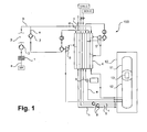
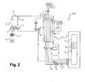
Das erfindungsgemäße Verfahren verwendet eine Luftzerlegungsanlage mit einem Hauptluftverdichter, einem Hauptwärmetauscher und einem Destillationssäulensystem mit einer auf einem ersten Druckniveau betriebenen Niederdrucksäule und einer auf einem zweiten Druckniveau betriebenen Hochdrucksäule. Die genannten und weitere verwendete Druckniveaus sind unten im Detail angegeben.The inventive method uses an air separation plant with a main air compressor, a main heat exchanger and a distillation column system with a operated at a first pressure level low pressure column and operated at a second pressure level high pressure column. The above and other used pressure levels are given below in detail.
In dem erfindungsgemäßen Verfahren wird ein Einsatzluftstrom, der die gesamte, der Luftzerlegungsanlage zugeführte Einsatzluft umfasst, in dem Hauptluftverdichter auf ein drittes Druckniveau verdichtet, welches mindestens 2 bar, insbesondere mindestens 4 bar, oberhalb des zweiten Druckniveaus liegt. Das dritte Druckniveau kann beispielsweise auch das Doppelte des zweiten Druckniveaus betragen. Es wird also ein HAP-Verfahren durchgeführt.In the method according to the invention, a feed air stream which comprises the entire feed air supplied to the air separation plant is compressed in the main air compressor to a third pressure level which is at least 2 bar, in particular at least 4 bar, above the second pressure level. The third pressure level may for example also be twice the second pressure level. Thus, a HAP method is performed.
Von dem verdichteten Einsatzluftstrom wird ein erster Anteil mindestens einmal in dem Hauptwärmetauscher abgekühlt und in einer ersten Entspannungsturbine ausgehend von dem dritten Druckniveau entspannt. Unter "mindestens einmal abgekühlt" wird hier und im Folgenden verstanden, dass ein entsprechender Strom vor und/oder nach der Entspannung mindestens einmal zumindest durch einen Abschnitt des Hauptwärmetauschers geführt wird.From the compressed feed air stream, a first portion is cooled at least once in the main heat exchanger and expanded in a first expansion turbine, starting from the third pressure level. By "cooled at least once" is understood here and below that a corresponding current before and / or after the relaxation at least once at least through a section of the main heat exchanger is performed.
Ein zweiter Anteil wird ähnlich behandelt, d.h. ebenfalls mindestens einmal in dem Hauptwärmetauscher abgekühlt und in einer zweiten Entspannungsturbine ausgehend von dem dritten Druckniveau entspannt. Bei dem zweiten Anteil handelt es sich um den sogenannten Turbinenstrom, seine Entspannung erfolgt, um in einer entsprechenden Anlage zusätzliche Kälte bereitstellen und diese regeln zu können.A second portion is treated similarly, ie also cooled at least once in the main heat exchanger and starting in a second expansion turbine relaxed from the third pressure level. The second part is the so-called turbine flow, its relaxation takes place in order to provide additional cooling in a corresponding system and to be able to regulate this.
Ein dritter Anteil wird auf ein viertes Druckniveau weiter verdichtet und dann ebenfalls mindestens einmal in dem Hauptwärmetauscher abgekühlt und ausgehend von dem vierten Druckniveau entspannt. Bei dem dritten Anteil handelt es sich um den sogenannten Drosselstrom, der, wie zuvor erläutert, insbesondere die Innenverdichtung ermöglicht.A third portion is further compressed to a fourth pressure level and then also cooled at least once in the main heat exchanger and expanded from the fourth pressure level. The third portion is the so-called inductor flow, which, as explained above, in particular allows internal compression.
Luft des ersten Anteils und/oder des zweiten Anteils und/oder des dritten Anteils wird anschließend auf dem ersten und/oder auf dem zweiten Druckniveau in das Destillationssäulensystem eingespeist. Typischerweise wird dabei die gesamte Luft des ersten Anteils auf dem zweiten Druckniveau in die Hochdrucksäule eingespeist. Die gesamte oder ein Teil der Luft des zweiten Anteils kann auf dem ersten Druckniveau in die Niederdrucksäule und/oder auf dem zweiten Druckniveau in die Hochdrucksäule eingespeist werden. Entsprechendes gilt für den dritten Anteil.Air of the first portion and / or the second portion and / or the third portion is then fed at the first and / or at the second pressure level in the distillation column system. Typically, the entire air of the first portion is fed to the second pressure level in the high-pressure column. All or part of the air of the second portion may be fed to the low pressure column at the first pressure level and / or to the high pressure column at the second pressure level. The same applies to the third share.
Die vorliegende Erfindung beruht auf der Erkenntnis, dass eine Kombination eines HAP-Verfahrens verbunden mit der energetischen Effizienz eines MAC/BAC-Verfahrens sowohl hinsichtlich der Erstellungs- als auch hinsichtlich der Betriebskosten einer Luftzerlegungsanlage besonders vorteilhaft ist. Wie erläutert, ist insbesondere der Einsatz eines Dichtfluidexpanders aus energetischer Sicht (also hinsichtlich der Betriebskosten) besonders günstig, wohingegen der Einsatz eines HAP-Verfahrens geringe Erstellungskosten ermöglicht. Der Einsatz eines Dichtfluidexpanders ist jedoch in herkömmlichen HAP-Verfahren nicht vorteilhaft, weil die durch einen Dichtfluidexpander erzielbare Energieeinsparung an die an dem Dichtfluidexpander auftretende Druckdifferenz gekoppelt ist. Bei geringeren Eintrittsdrücken und damit geringeren Druckdifferenzen ist der Einsatz insgesamt weniger lohnend. Auch die durch die erhöhten Drücke eines MAC/BAC-Verfahrens verbesserten Q,T-Profile lassen sich herkömmlicherweise mittels eines HAP-Verfahrens nicht erreichen.The present invention is based on the recognition that a combination of a HAP process associated with the energy efficiency of a MAC / BAC process is particularly advantageous both in terms of the creation and in the operating costs of an air separation plant. As explained, in particular the use of a sealing fluid expander from an energetic point of view (ie in terms of operating costs) is particularly favorable, whereas the use of a HAP method allows low creation costs. However, the use of a sealing fluid expander is not advantageous in conventional HAP processes because the energy saving achievable by a sealing fluid expander is coupled to the pressure difference occurring at the sealing fluid expander. At lower inlet pressures and thus lower pressure differences, the use is less rewarding overall. Also, improved by the increased pressures of a MAC / BAC process Q, T-profiles can not be conventionally achieved by a HAP method.
Bei HAP-Verfahren ist der Enddruck des Hauptluftverdichters (hier also das "dritte Druckniveau") sowohl von den Innenverdichtungsdrücken, also den Drücken der mittels Innenverdichtung bereitzustellenden gasförmigen Luftprodukte, als auch von der Menge der zu gewinnenden flüssigen Luftprodukte abhängig. Erstere Abhängigkeit ergibt sich aus der im Wesentlichen durch den Druck eingestellten Verdampfungskapazität eines entsprechenden Stroms, letztere aus der durch die Entnahme der flüssigen Luftprodukte "entzogenen" Kältemenge, die durch Entspannung eines weiteren Stroms ausgeglichen werden muss.In HAP process, the final pressure of the main air compressor (in this case the "third pressure level") is determined both by the internal compression pressures, ie the pressures of the gaseous air products to be provided by internal compression, and by the amount of liquid air products to be extracted. The first dependence results from the vaporization capacity of a corresponding stream, which is essentially set by the pressure, the latter from the amount of cold "withdrawn" by the removal of the liquid air products, which must be compensated for by relaxation of another stream.
Da die Luftmenge des Einsatzluftstroms, also die Luftmenge der gesamten, durch den Hauptluftverdichter verdichteten Einsatzluft, durch die Menge der erzeugten Luftprodukte festgelegt ist, kann der Anlage aber nur über eine Variation des Enddrucks des Hauptluftverdichters mehr oder weniger Exergie zugeführt werden. Aufgrund technisch-ökonomischer Grenzen (eingesetzte Rohrklassen) ist dieser typischerweise auf ca. 23 bar limitiert.Since the amount of air of the feed air stream, that is, the amount of air of the entire, compressed by the main air compressor feed air is determined by the amount of air products generated, but the system can be fed more or less exergy only via a variation of the discharge pressure of the main air compressor. Due to technical-economical limits (used pipe classes) this is typically limited to approx. 23 bar.
Unter diesen Randbedingungen kann in herkömmlichen HAP-Verfahren kein ausreichender Druck zur Verfügung gestellt werden, der den Einsatz einer Flüssigturbine vorteilhaft erscheinen lässt. Wie erwähnt, ist der Einsatz einer Flüssigturbine nur dann technisch vorteilhaft, wenn hierüber eine ausreichende Druckdifferenz erzielt werden kann.Under these conditions, sufficient pressure can not be provided in conventional HAP processes which makes the use of a liquid turbine appear advantageous. As mentioned, the use of a liquid turbine is only technically advantageous if a sufficient pressure difference can be achieved over this.
Die vorliegende Erfindung schlägt daher vor, den dritten Anteil nacheinander in einem Nachverdichter, einem ersten Turbinenbooster und einem zweiten Turbinenbooster auf das vierte Druckniveau weiter zu verdichten. Es werden also statt den üblichen maximal zwei Verdichtungsschritten, die typischerweise durch zwei Turbinenbooster realisiert sind, zumindest drei Verdichtungsschritte eingesetzt, von denen zwei durch jeweils einen Turbinenbooster und einer durch einen Nachverdichter realisiert werden. Hierdurch kann ein deutlich höheres viertes Druckniveau erzielt werden.The present invention therefore proposes to further densify the third portion successively in a booster compressor, a first turbine booster and a second turbine booster to the fourth pressure level. Thus, instead of the usual maximum of two compression steps, which are typically realized by two turbine boosters, at least three compression steps are used, two of which are implemented by a respective turbine booster and one by a secondary compressor. As a result, a significantly higher fourth pressure level can be achieved.
Wie erwähnt, kommen herkömmlicherweise zwar in MAC/BAC-Verfahren, jedoch nicht in HAP-Verfahren, Nachverdichter zum Einsatz, die mittels extern zugeführter Energie angetrieben werden. Die vorliegende Erfindung schlägt jedoch ebendies vor. Bei dem im Rahmen der vorliegenden Erfindung eingesetzten Nachverdichter handelt es sich um einen mit externer Energie angetriebenen Verdichter, der also nicht oder zumindest nicht ausschließlich durch Entspannung eines zuvor in der Luftzerlegungsanlage selbst verdichteten Fluids angetrieben wird. Zu den unterschiedlichen Möglichkeiten, einen erfindungsgemäß bereitgestellten Nachverdichter mit externer Energie anzutreiben, sei auf die Erläuterungen unten verwiesen.As mentioned, although in MAC / BAC processes, but not in HAP processes, recompressors which are driven by externally supplied energy are conventionally used. However, the present invention proposes the same. The booster used in the context of the present invention is a compressor driven by external energy, which is thus not or at least not exclusively driven by expansion of a fluid which has previously been compressed in the air separation plant. To the different possibilities, one In accordance with the invention, to drive additional compressors with external energy, reference is made to the explanations below.
Die Erfindung ermöglicht durch die genannte Verdichtung eine Bereitstellung des dritten Anteils (Drosselstrom) auf einem deutlich erhöhten vierten Druckniveau, das den Einsatz eines Dichtfluidexpanders energetisch sinnvoll macht. Daher ist erfindungsgemäß vorgesehen, zum Entspannen des dritten Anteils einen entsprechenden Dichtfluidexpander zu verwenden, dem der dritte Anteil in flüssigem Zustand und auf dem vierten (überkritischen) Druckniveau zugeführt wird.The invention makes it possible by the said compression to provide the third portion (throttle flow) at a significantly increased fourth pressure level, which makes the use of a sealing fluid expander energetically meaningful. Therefore, it is provided according to the invention to use a corresponding Dichtfluidexpander to relax the third portion to which the third portion is supplied in the liquid state and at the fourth (supercritical) pressure level.
Der dritte Anteil (Drosselstrom) kann dem zweiten Turbinenbooster insbesondere je nach der Menge des oder der flüssigen Luftprodukte, die in einer entsprechenden Luftzerlegungsanlage gewonnen und dieser entnommen werden sollen, auf unterschiedlichen Temperaturniveaus zugeführt werden.The third portion (throttle flow) may be supplied to the second turbine booster in particular depending on the amount of liquid or liquid products that are obtained in a corresponding air separation plant and to be removed, at different temperature levels.
Für eine Bereitstellung größerer Mengen eines oder mehrerer flüssiger Luftprodukte hat es sich als besonders vorteilhaft erwiesen, den dritten Anteil dem ersten Turbinenbooster auf einem Temperaturniveau von 0 bis 50 °C und dem zweiten Turbinenbooster auf einem Temperaturniveau von -40 bis 50 °C zuzuführen. Der zweite Turbinenbooster ist daher kein typischer Kaltverdichter, also kein "kalter" Turbinenbooster. Zwar wird diesem der dritte Anteil (Drosselstrom) ggf. deutlich unterhalb der Umgebungstemperatur zugeführt, stromab des zweiten Turbinenboosters liegt seine Temperatur jedoch oberhalb der Umgebungstemperatur.For a provision of larger amounts of one or more liquid air products, it has proven to be particularly advantageous to supply the third portion of the first turbine booster at a temperature level of 0 to 50 ° C and the second turbine booster at a temperature level of -40 to 50 ° C. The second turbine booster is therefore not a typical cold compressor, so no "cold" turbine booster. Although this is the third portion (throttle current) possibly supplied well below the ambient temperature, downstream of the second turbine booster, however, its temperature is above the ambient temperature.
Sollen einer entsprechenden Luftzerlegungsanlage größere Mengen von Luftprodukten flüssig entnommen werden, sind "kalte" Turbinenbooster weniger vorteilhaft, weil die gesamte zur Verfügung stehende Kälteleistung zur Bereitstellung dieser flüssigen Luftprodukte verwendet wird. Ein kalter Turbinenbooster trägt aber unvermeidlich Wärme in das System ein, da die Verdichtungswärme aus dem verdichteten Strom typischerweise nicht in einem Nachkühler, sondern nur im Hauptwärmetauscher, verbunden mit einem entsprechendem Wärmeeintrag, abgeführt werden kann. Ein bei höheren Eintrittstemperaturen betriebener Turbinenbooster, bei dem der verdichtete Strom deutlich höhere Temperaturen aufweist als beispielsweise vorhandenes Kühlwasser, ermöglicht eine effektive Wärmeabfuhr in einem üblichen Nachkühler. Durch das Abführen der Verdichtungswärme stromab des zweiten Turbinenboosters ist die Verdichtung in diesem weitgehend wärmeneutral, da die Verdichtungsarbeit hier durch den Nachkühler kompensiert wird.If a corresponding air separation plant larger quantities of air products are removed liquid, "cold" turbine boosters are less advantageous because the entire available cooling capacity is used to provide these liquid air products. However, a cold turbine booster inevitably introduces heat into the system since the heat of compression from the compressed stream typically can not be dissipated in an aftercooler, but only in the main heat exchanger, coupled with a corresponding input of heat. A turbine booster operated at higher inlet temperatures, in which the compressed stream has significantly higher temperatures than, for example, existing cooling water, enables effective heat removal in a conventional aftercooler. By dissipating the heat of compression downstream of the second turbine booster is the compression in this largely neutral in terms of heat, since the compression work is compensated here by the aftercooler.
Insgesamt erlaubt die Verwendung eines bei den erwähnten höheren Eintrittstemperaturen betriebenen zweiten Turbinenboosters daher eine Entnahme einer vergleichsweise großen Menge von 3 bis 10 Mol.-% des Einsatzluftstroms in Form von flüssigen Luftprodukten, beispielsweise flüssigem Sauerstoff (LOX), flüssigem Stickstoff (LIN) und/oder flüssigem Argon (LAR).Overall, the use of a second turbine booster operated at the above-mentioned higher inlet temperatures therefore makes it possible to take off a comparatively large amount of from 3 to 10 mol% of the feed air stream in the form of liquid air products, for example liquid oxygen (LOX), liquid nitrogen (LIN) and / or liquid argon (LAR).
Für eine Luftzerlegungsanlage, die hingegen überwiegend oder ausschließlich gasförmige Luftprodukte bereitstellen soll (die aber auch beispielsweise mittels Innenverdichtungsverfahren aus flüssigen Zwischenprodukten gewonnen werden können), ist es hingegen vorteilhaft, den dritten Anteil dem ersten Turbinenbooster auf einem Temperaturniveau von 0 bis 50 °C und dem zweiten Turbinenbooster auf einem Temperaturniveau von -140 bis -20 °C zuzuführen. Der zweite Turbinenbooster ist in diesem Fall ein typischer Kaltverdichter, also ein "kalter" Turbinenbooster. Diesem wird der dritte Anteil (Drosselstrom) unterhalb der Umgebungstemperatur zugeführt, stromab des zweiten Turbinenboosters liegt seine Temperatur weiterhin (deutlich) unterhalb der Umgebungstemperatur. Die Temperatur des in dem zweiten Turbinenboosters verdichteten dritten Anteils kann direkt stromab des zweiten Turbinenboosters beispielsweise bei -90 bis 20 °C liegen.For an air separation plant, however, the predominantly or exclusively provide gaseous air products (but can also be obtained, for example by means of internal compression of liquid intermediates), it is advantageous to the third portion of the first turbine booster at a temperature level of 0 to 50 ° C and the second turbine booster at a temperature level of -140 to -20 ° C supply. The second turbine booster is in this case a typical cold compressor, so a "cold" turbine booster. This is the third portion (inductor current) supplied below the ambient temperature, downstream of the second turbine booster, its temperature is still (significantly) below the ambient temperature. The temperature of the third portion compressed in the second turbine booster may be, for example, at -90 to 20 ° C. directly downstream of the second turbine booster.
Ein kalter Turbinenbooster trägt Wärme in das System ein, da die Verdichtungswärme aus dem verdichteten Strom typischerweise nicht in einem Nachkühler, der mit Kühlwasser betrieben wird, sondern nur im Hauptwärmetauscher selbst, verbunden mit einem entsprechenden Wärmeeintrag, abgeführt wird. Ein kalter Turbinenbooster ermöglicht durch diesen im vorliegenden Fall gewollten Wärmeeintrag eine besonders gute Erwärmung und Entflüssigung von Innenverdichtungsprodukten und eignet sich für Luftzerlegungsanlagen zur Erzeugung großer Mengen entsprechender gasförmiger Druckprodukte und vergleichsweise geringer Mengen an flüssigen Luftprodukten.A cold turbine booster adds heat to the system because the heat of compression from the compressed stream is typically not dissipated in an aftercooler operating with cooling water but only in the main heat exchanger itself, with associated heat input. By means of this heat input, which is intended in the present case, a cold turbine booster permits particularly good heating and liquefaction of internal compression products and is suitable for air separation plants for generating large quantities of corresponding gaseous printed products and comparatively small amounts of liquid air products.
Insgesamt erlaubt die Verwendung eines bei den erwähnten niedrigen Eintrittstemperaturen betriebenen zweiten Turbinenboosters daher eine Entnahme einer vergleichsweise geringen Menge von bis zu 3 Mol.-% des Einsatzluftstroms in Form von flüssigen Luftprodukten, beispielsweise flüssigem Sauerstoff (LOX), flüssigem Stickstoff (LIN) und/oder flüssigem Argon (LAR).
Die Erfindung sieht vorteilhafterweise vor, die genannten Turbinenbooster jeweils mit einer der Entspannungsturbinen anzutreiben, beispielsweise den ersten Turbinenbooster mit der zweiten Entspannungsturbine und den zweiten Turbinenbooster mit der ersten Entspannungsturbine.Overall, therefore, the use of a second turbine booster operated at the mentioned low inlet temperatures permits removal of a comparatively small amount of up to 3 mol% of the feed air stream in Form of liquid air products, for example liquid oxygen (LOX), liquid nitrogen (LIN) and / or liquid argon (LAR).
The invention advantageously provides for driving the turbine boosters in each case with one of the expansion turbines, for example, the first turbine booster with the second expansion turbine and the second turbine booster with the first expansion turbine.
Der zusätzlich zur Verdichtung des dritten Anteils (Drosselstrom) eingesetzte Nachverdichter wird hingegen mit externer Energie angetrieben, also nicht über zugeordnete Entspannungsturbinen, die jeweils Luftanteile des Einsatzluftstroms entspannen. Vorteilhaft kann beispielsweise sein, den Nachverdichter mit Hochdruckfluid und/oder elektrisch und/oder zusammen mit einer Verdichterstufe des Hauptluftverdichters anzutreiben. In letzterem Fall sind zumindest eine Verdichterstufe des Hauptluftverdichters und zumindest eine Verdichterstufe des Nachverdichters beispielsweise auf einer gemeinsamen Welle angeordnet. Auch ein Einsatz mehrerer entsprechender Maßnahmen gleichzeitig kann erfolgen.The additional compressor used in addition to the compression of the third portion (throttle flow), however, is driven by external energy, so not via associated expansion turbines, each relax the air portions of the feed air stream. It can be advantageous, for example, to drive the secondary compressor with high-pressure fluid and / or electrically and / or together with a compressor stage of the main air compressor. In the latter case, at least one compressor stage of the main air compressor and at least one compressor stage of the secondary compressor are arranged, for example, on a common shaft. Even a use of several appropriate measures can be done simultaneously.
Besonders vorteilhaft ist es, den dritten Anteil vor und nach dem weiteren Verdichten in dem zweiten Turbinenbooster in dem Hauptwärmetauscher abzukühlen. Der dritte Anteil wird dem Hauptwärmetauscher dabei auf geeigneten Temperaturniveaus entnommen bzw. zugeführt. Wie erläutert, kann ferner in Fällen, in denen der zweite Turbinenbooster bei den erwähnten höheren Temperaturen betrieben wird, eine zusätzliche Nachkühlung stromab des zweiten Turbinenboosters und vor einer erneuten Einspeisung in den Hauptwärmetauscher vorgesehen sein. Wird dagegen der zweite Turbinenbooster bei den erwähnten geringeren Temperaturen betrieben, ist dies, wie erläutert, nicht der Fall.It is particularly advantageous to cool the third portion before and after the further compression in the second turbine booster in the main heat exchanger. The third portion is taken from or fed to the main heat exchanger at appropriate temperature levels. As explained above, in cases where the second turbine booster is operated at the higher temperatures mentioned, additional after-cooling may be provided downstream of the second turbine booster and before being reintroduced into the main heat exchanger. If, however, the second turbine booster operated at the lower temperatures mentioned, this is, as explained, not the case.
Die Abkühlung in dem Hauptwärmetauscher nach dem Nachverdichten in dem zweiten Turbinenbooster erfolgt dabei vorteilhafterweise von einem Temperaturniveau, das sich nach der Ein- und Austrittstemperatur des zweiten Turbinenboosters und einer möglichen Nachkühlung richtet, also von beispielsweise 10 bis 50 °C oder -90 bis 20 °C auf ein Temperaturniveau von -140 bis -180 °C.The cooling in the main heat exchanger after the recompression in the second turbine booster is advantageously carried out by a temperature level that depends on the inlet and outlet temperature of the second turbine booster and a possible aftercooling, ie, for example, 10 to 50 ° C or -90 to 20 ° C to a temperature level of -140 to -180 ° C.
Vorteilhaft kann auch sein, wenn der erste Anteil vor dem Entspannen in der ersten Entspannungsturbine in dem Hauptwärmetauscher auf ein Temperaturniveau von 0 bis -150 °C abgekühlt wird. Vorteilhafterweise wird der erste Anteil nach dem Entspannen in der ersten Entspannungsturbine in dem Hauptwärmetauscher auf ein Temperaturniveau von -130 bis -180 °C abgekühlt. Mit anderen Worten wird der erste Anteil nach der Entspannung in der ersten Entspannungsturbine also nochmals durch den Hauptwärmetauscher geführt.It may also be advantageous if the first portion before relaxing in the first expansion turbine in the main heat exchanger to a temperature level of 0 to -150 ° C is cooled. Advantageously, the first portion is cooled to a temperature level of -130 to -180 ° C after relaxing in the first expansion turbine in the main heat exchanger. In other words, after the expansion in the first expansion turbine, the first portion is again passed through the main heat exchanger.
Der zweite Anteil wird vorteilhafterweise vor dem Entspannen in der zweiten Entspannungsturbine in dem Hauptwärmetauscher auf ein Temperaturniveau von -50 bis -150 °C abgekühlt.The second portion is advantageously cooled to a temperature level of -50 to -150 ° C before relaxing in the second expansion turbine in the main heat exchanger.
Im Rahmen der vorliegenden Erfindung beträgt vorteilhafterweise das erste Druckniveau 1 bis 2 bar und/oder das zweite Druckniveau 5 bis 6 bar und/oder das dritte Druckniveau 8 bis 23 bar und/oder das vierte Druckniveau 50 bis 70 bar Absolutdruck, wenn der zweite Turbinenbooster bei den erwähnten höheren Temperaturen betrieben wird. Wird der zweite Turbinenbooster bei den erwähnten niedrigeren Temperaturen betrieben, beträgt vorteilhafterweise das erste Druckniveau 1 bis 2 bar und/oder das zweite Druckniveau 5 bis 6 bar und/oder das dritte Druckniveau 8 bis 23 bar und/oder das vierte Druckniveau 50 bis 70 bar Absolutdruck. Das dritte Druckniveau lässt sich dabei jeweils noch mit üblichen HAP-Hauptluftverdichtern erreichen, das vierte, insbesondere mit Hilfe des genannten Nachverdichters erzielte Druckniveau ermöglicht den Einsatz eines Dichtfluidexpanders. Das vierte Druckniveau liegt dabei bei überkritischem Druck.In the context of the present invention is advantageously the
Das erfindungsgemäße Verfahren ermöglicht es insbesondere, dem Destillationssäulensystem zumindest ein flüssiges Luftprodukt zu entnehmen, flüssig mit Druck zu beaufschlagen, in dem Hauptwärmetauscher zu verdampfen oder in den überkritischen Zustand zu überführen (zu "entflüssigen") und als wenigstens ein Innenverdichtungsprodukt aus der Luftzerlegungsanlage auszuführen, also wie mehrfach erwähnt zum Einsatz mit einem Innenverdichtungsverfahren.The process according to the invention makes it possible, in particular, to remove at least one liquid air product from the distillation column system, to pressurize it in the main heat exchanger or to convert it into the supercritical state (to "liquefy") and to carry out at least one internal compression product from the air separation plant. So as mentioned several times for use with a Innenverdichtungsverfahren.
Das wenigstens eine Innenverdichtungsprodukt kann bei einem Druck von 6 bar bis 100 bar aus der Luftzerlegungsanlage ausgeführt werden. Das erfindungsgemäße Verfahren eignet sich aufgrund des zusätzlichen, oben erläuterten Wärmeeintrags insbesondere zur Bereitstellung von Innenverdichtungsprodukten bei vergleichsweise hohem Druck, d.h. bei mindestens 30 bar, wenn der zweite Turbinenbooster bei den erwähnten geringeren Temperaturen betrieben wird.The at least one internal compression product can be carried out at a pressure of 6 bar to 100 bar from the air separation plant. Due to the additional heat input explained above, the method according to the invention is particularly suitable for providing internal compaction products in comparison high pressure, ie at least 30 bar, when the second turbine booster is operated at the mentioned lower temperatures.
Zu den Merkmalen der erfindungsgemäßen Luftzerlegungsanlage sei auf den entsprechenden Vorrichtungsanspruch verwiesen. Eine derartige Luftzerlegungsanlage weist insbesondere sämtliche Mittel auf, die sie zur Durchführung eines zuvor erläuterten Verfahrens befähigen. Auf die Merkmale und Vorteile, die zuvor erläutert wurden, wird daher ausdrücklich verwiesen.For the features of the air separation plant according to the invention, reference is made to the corresponding device claim. In particular, such an air separation plant has all the means which enable it to carry out a previously explained method. The features and advantages discussed above are therefore expressly referred to.
Die Erfindung wird nachfolgend unter Bezugnahme auf die beigefügte Zeichnung näher erläutert, welche bevorzugte Ausführungsformen der Erfindung zeigen.The invention will be explained in more detail below with reference to the accompanying drawing, which show preferred embodiments of the invention.
Kurze Beschreibung der Zeichnung
-
Figur 1 -
Figur 2
-
FIG. 1 shows an air separation plant according to an embodiment of the invention in the form of a schematic diagram of the system. -
FIG. 2 shows an air separation plant according to an embodiment of the invention in the form of a schematic diagram of the system.
In
Stromab des Hauptluftverdichters 2 wird der in diesem verdichtete Einsatzluftstrom a, bei dem es sich hier um die gesamte, in der Luftzerlegungsanlage 100 behandelte Einsatzluft handelt, einer nicht dargestellten Reinigungseinrichtung 3 zugeführt und dort beispielsweise von Restfeuchtigkeit und Kohlendioxid befreit. Es wird ein verdichteter (und aufgereinigter) Einsatzluftstrom b erhalten, der stromab der Reinigungseinrichtung 3 auf einem Druckniveau von beispielsweise 15 bis 23 bar, im Rahmen dieser Anmeldung als drittes Druckniveau bezeichnet, vorliegt. Das dritte Druckniveau liegt im dargestellten Beispiel deutlich über dem Betriebsdruck einer typischen Hochdrucksäule einer Luftzerlegungsanlage, wie eingangs erläutert. Es handelt sich damit um ein HAP-Verfahren.Downstream of the
Der Einsatzluftstrom b wird nacheinander in die Ströme c, d und e aufgeteilt. Der Strom c wird im Rahmen dieser Anmeldung als erster Anteil, der Strom d als zweiter Anteil und der Strom e als dritter Anteil des Einsatzluftstroms b bezeichnet.The feed air stream b is successively divided into the streams c, d and e. In the context of this application, the current c is referred to as the first portion, the current d as the second portion, and the current e as the third portion of the feed air flow b.
Die Ströme c und d werden getrennt voneinander warmseitig einem Hauptwärmetauscher 4 der Luftzerlegungsanlage 100 zugeführt und diesem auf unterschiedlichen Zwischentemperaturniveaus wieder entnommen. Der Strom c wird nach der Entnahme aus dem Hauptwärmetauscher 4 in einer Entspannungsturbine 5, die im Rahmen dieser Anmeldung als erste Entspannungsturbine bezeichnet wird, auf ein Druckniveau von beispielsweise 5 bis 6 bar, das im Rahmen dieser Anmeldung als zweites Druckniveau bezeichnet wird, entspannt, und nochmals durch einen Abschnitt des Hauptwärmetauschers 4 geführt. Der Strom d wird nach der Entnahme aus dem Hauptwärmetauscher 4 in einer Entspannungsturbine 6, die im Rahmen dieser Anmeldung als zweite Entspannungsturbine bezeichnet wird, ebenfalls auf das zweite Druckniveau entspannt.The streams c and d are separated from each other warmly supplied to a
Bei dem Strom e handelt es sich um den sogenannten Drosselstrom, der insbesondere die Innenverdichtung ermöglicht. Der Strom e wird hierzu zunächst in einem Nachverdichter 7 und anschließend in zwei Turbinenboostern, die jeweils durch die erste Entspannungsturbine 5 und die zweite Entspannungsturbine 6 angetrieben werden (nicht gesondert bezeichnet), nachverdichtet. Der durch die zweite Entspannungsturbine 6 angetriebene Turbinenbooster wird hier als erster Turbinenbooster, der durch die erste Entspannungsturbine 5 angetriebene Turbinenbooster hingegen als zweiter Turbinenbooster bezeichnet. Grundsätzlich kann die Zuordnung der Turbinenbooster zu den Entspannungsturbinen 5, 6 auch umgekehrt sein. Die Nachverdichtung erfolgt auf ein Druckniveau von beispielsweise 50 bis 70 bar, das im Rahmen dieser Anmeldung als viertes Druckniveau bezeichnet wird. Stromab des Nachverdichters 7 und stromauf der Turbinenbooster liegt der Strom e auf einem Druckniveau von beispielsweise 26 bis 36 bar vor. Der Nachverdichter 7 wird mit externer Energie, d.h. nicht durch eine Entspannung von verdichteten Luftanteilen des Einsatzluftstroms b, angetrieben.The current e is the so-called inductor current, which in particular enables internal compression. The current e is for this purpose first in a
Nach den Nachverdichtungsschritten in den zwei Turbinenboostern wird der Strom e jeweils in nicht gesondert bezeichneten Nachkühlern der Turbinenbooster auf eine Temperatur rückgekühlt, die etwa der Kühlwassertemperatur entspricht. Eine weitere Abkühlung erfolgt wie dargestellt mittels des Hauptwärmetauschers 4 je nach Bedarf. Auf dem vierten Druckniveau wird der Strom e also nochmals durch einen Nachkühler und danach durch den Hauptwärmetauscher 4 geführt und anschließend in einem Dichtfluidexpander 8 entspannt. Das vierte Druckniveau liegt deutlich oberhalb des kritischen Drucks für Stickstoff und oberhalb des kritischen Drucks für Sauerstoff.After the recompression steps in the two turbine boosters, the current e is recooled in each case in non-separately designated aftercoolers of the turbine boosters to a temperature which corresponds approximately to the cooling water temperature. A further cooling takes place as shown by means of the
Nach der Abkühlung in dem Hauptwärmetauscher 4 und stromauf des Dichtfluidexpanders 8 befindet sich der Strom e in flüssigem Zustand bei überkritischem Druck. Der Dichtfluidexpander 8 ist beispielsweise mit einem Generator oder einer Ölbremse gekoppelt (ohne Bezeichnung). Nach der Entspannung liegt der Strom e hier auf dem zweiten Druckniveau vor. Er ist weiterhin flüssig, befindet sich jedoch auf einem unterkritischen Druck.After cooling in the
Das Destillationssäulensystem 10 ist stark vereinfacht gezeigt. Es umfasst zumindest eine auf einem Druckniveau von 1 bis 2 bar (hier als erstes Druckniveau bezeichnet) betriebene Niederdrucksäule 11 und eine auf dem zweiten Druckniveau betriebene Hochdrucksäule 12 eines Doppelsäulensystems, in dem die Niederdrucksäule 11 und die Hochdrucksäule 12 über einen Hauptkondensator 13 in wärmetauschender Verbindung stehen. Auf die konkrete Darstellung von die Niederdrucksäule 11 und die Hochdrucksäule 12 speisenden und diese und den Hauptkondensator 13 verbindenden Leitungen, Ventilen, Pumpen, weiteren Wärmetauschern und dergleichen wurde der Übersichtlichkeit halber verzichtet.The
Die Ströme c, d und e werden im dargestellten Beispiel in die Hochdrucksäule 12 eingespeist. Es kann jedoch auch vorgesehen sein, beispielsweise den Strom d und/oder den Strom e nach entsprechender Entspannung in die Niederdrucksäule 11 und/oder Anteile nicht in das Destillationssäulensystem einzuspeisen.The streams c, d and e are fed into the
Dem Destillationssäulensystem 10 können im dargestellten Beispiel die Ströme f, g und h entnommen werden. Die Luftzerlegungsanlage 100 ist zur Durchführung eines Innenverdichtungsverfahrens eingerichtet, wie mehrfach erläutert. Im dargestellten Beispiel werden die Ströme f und g, bei denen es sich um einen flüssigen, sauerstoffreichen Strom f und einen flüssigen, stickstoffreichen Strom g handeln kann, daher mittels Pumpen 9 in flüssigem Zustand druckbeaufschlagt und in dem Hauptwärmetauscher 4 verdampft oder, je nach Druck, vom flüssigen in den überkritischen Zustand überführt. Fluid der Ströme f und g kann der Luftzerlegungsanlage 100 als innenverdichteter Sauerstoff (GOX-IC) bzw. innenverdichteter Stickstoff (GAN-IC) entnommen werden. Der Strom h veranschaulicht einen oder mehrere dem Destillationssäulensystem 10 in gasförmigem Zustand auf dem ersten Druckniveau entnommene Ströme.The
In
Der Einsatzluftstrom b liegt auch hier stromab der Reinigungseinrichtung 3 auf einem dritten Druckniveau vor, das jedoch hier beispielsweise 9 bis 17 bar beträgt. Das vierte Druckniveau, auf das der Strom e (Drosselstrom) verdichtet wird, beträgt hier beispielsweise 30 bis 80 bar. Während der Strom e auch hier nach dem Nachverdichtungsschritt in dem ersten Turbinenbooster in einem nicht gesondert bezeichneten Nachkühler auf eine Temperatur rückgekühlt wird, die etwa der Kühlwassertemperatur entspricht, erfolgt eine Abkühlung stromab des zweiten Turbinenboosters nur mittels des Hauptwärmetauschers 4, nicht jedoch mittels eines Nachkühlers wie in der Luftzerlegungsanlage 100 gemäß
Im dargestellten Beispiel der Luftzerlegungsanlage 100 erfolgt der Antrieb des Nachverdichters 7 gemeinsam mit einer oder mehreren Verdichterstufen des Hauptluftverdichters 2 und unter Verwendung eines Druckfluids, z.B. Druckdampf, das in einer Entspannungsturbine (nicht gesondert bezeichnet) entspannt wird. Wie erwähnt, eignet sich eine Luftzerlegungsanlage 100 gemäß
Claims (15)
dadurch gekennzeichnet, dass
characterized in that
gekennzeichnet durch Mittel, die dafür eingerichtet sind,
characterized by means adapted for
Priority Applications (6)
| Application Number | Priority Date | Filing Date | Title |
|---|---|---|---|
| EP14002683.2A EP2980514A1 (en) | 2014-07-31 | 2014-07-31 | Method for the low-temperature decomposition of air and air separation plant |
| EP15742185.0A EP3175192A1 (en) | 2014-07-31 | 2015-07-28 | Method for the cryogenic separation of air and air separation plant |
| US15/328,995 US10480853B2 (en) | 2014-07-31 | 2015-07-28 | Method for the cryogenic separation of air and air separation plant |
| PCT/EP2015/001554 WO2016015860A1 (en) | 2014-07-31 | 2015-07-28 | Method for the cryogenic separation of air and air separation plant |
| CN201580049883.8A CN106716033B (en) | 2014-07-31 | 2015-07-28 | Method for the cryogenic separation of air and air separation plant |
| SA517380791A SA517380791B1 (en) | 2014-07-31 | 2017-01-25 | Method for the cryogenic separation of air and air separation plant |
Applications Claiming Priority (1)
| Application Number | Priority Date | Filing Date | Title |
|---|---|---|---|
| EP14002683.2A EP2980514A1 (en) | 2014-07-31 | 2014-07-31 | Method for the low-temperature decomposition of air and air separation plant |
Publications (1)
| Publication Number | Publication Date |
|---|---|
| EP2980514A1 true EP2980514A1 (en) | 2016-02-03 |
Family
ID=51266069
Family Applications (2)
| Application Number | Title | Priority Date | Filing Date |
|---|---|---|---|
| EP14002683.2A Withdrawn EP2980514A1 (en) | 2014-07-31 | 2014-07-31 | Method for the low-temperature decomposition of air and air separation plant |
| EP15742185.0A Pending EP3175192A1 (en) | 2014-07-31 | 2015-07-28 | Method for the cryogenic separation of air and air separation plant |
Family Applications After (1)
| Application Number | Title | Priority Date | Filing Date |
|---|---|---|---|
| EP15742185.0A Pending EP3175192A1 (en) | 2014-07-31 | 2015-07-28 | Method for the cryogenic separation of air and air separation plant |
Country Status (5)
| Country | Link |
|---|---|
| US (1) | US10480853B2 (en) |
| EP (2) | EP2980514A1 (en) |
| CN (1) | CN106716033B (en) |
| SA (1) | SA517380791B1 (en) |
| WO (1) | WO2016015860A1 (en) |
Cited By (25)
| Publication number | Priority date | Publication date | Assignee | Title |
|---|---|---|---|---|
| EP3179187A1 (en) * | 2015-12-07 | 2017-06-14 | Linde Aktiengesellschaft | Method for obtaining a liquid and a gaseous oxygen-rich air product in an air breakdown apparatus and air breakdown apparatus |
| EP3312533A1 (en) | 2016-10-18 | 2018-04-25 | Linde Aktiengesellschaft | Method for air separation and air separation plant |
| DE102017010001A1 (en) | 2016-11-04 | 2018-05-09 | Linde Aktiengesellschaft | Process and installation for the cryogenic separation of air |
| DE102016015292A1 (en) | 2016-12-22 | 2018-06-28 | Linde Aktiengesellschaft | Method of providing one or more air products with an air separation plant |
| EP3343158A1 (en) | 2016-12-28 | 2018-07-04 | Linde Aktiengesellschaft | Method for producing one or more air products, and air separation system |
| EP3410050A1 (en) | 2017-06-02 | 2018-12-05 | Linde Aktiengesellschaft | Method for producing one or more air products and air separation system |
| WO2018219501A1 (en) | 2017-05-31 | 2018-12-06 | Linde Aktiengesellschaft | Method for obtaining one or more air products and air separation plant |
| DE202018005045U1 (en) | 2018-10-31 | 2018-12-17 | Linde Aktiengesellschaft | Plant for the production of argon by cryogenic separation of air |
| WO2019214847A1 (en) | 2018-05-07 | 2019-11-14 | Linde Aktiengesellschaft | Method for obtaining one or more air products and air separation system |
| EP3620739A1 (en) | 2018-09-05 | 2020-03-11 | Linde Aktiengesellschaft | Method for the low-temperature decomposition of air and air separation plant |
| WO2020074120A1 (en) | 2018-10-09 | 2020-04-16 | Linde Aktiengesellschaft | Method for obtaining one or more air products and air separation system |
| WO2020083520A1 (en) | 2018-10-26 | 2020-04-30 | Linde Aktiengesellschaft | Method for obtaining one or more air products, and air separation unit |
| EP3671085A1 (en) | 2018-12-18 | 2020-06-24 | Linde GmbH | Assembly and method for recovering compression heat from the air which is compressed and processed in an air processing system |
| DE102019000335A1 (en) | 2019-01-18 | 2020-07-23 | Linde Aktiengesellschaft | Process for providing air products and air separation plant |
| EP3696486A1 (en) | 2019-02-13 | 2020-08-19 | Linde GmbH | Method and apparatus for providing one or more gaseous oxygen rich air products |
| EP3699534A1 (en) | 2019-02-19 | 2020-08-26 | Linde GmbH | Method and air separation system for variable provision of a gaseous pressurised air product |
| EP3699535A1 (en) | 2019-02-19 | 2020-08-26 | Linde GmbH | Method and air separation system for variable provision of a gaseous pressurised air product |
| DE202021002439U1 (en) | 2021-07-17 | 2021-10-20 | Linde Gmbh | compressor |
| DE202021002895U1 (en) | 2021-09-07 | 2022-02-09 | Linde GmbH | Plant for the low-temperature separation of air |
| WO2022053172A1 (en) | 2020-09-08 | 2022-03-17 | Linde Gmbh | Method for obtaining one or more air products, and air fractionation plant |
| WO2022053173A1 (en) | 2020-09-08 | 2022-03-17 | Linde Gmbh | Method and plant for cryogenic fractionation of air |
| WO2022111850A1 (en) | 2020-11-24 | 2022-06-02 | Linde Gmbh | Process and plant for cryogenic separation of air |
| WO2022263013A1 (en) | 2021-06-17 | 2022-12-22 | Linde Gmbh | Method and plant for providing a pressurized oxygen-rich, gaseous air product |
| WO2023030689A1 (en) | 2021-09-02 | 2023-03-09 | Linde Gmbh | Method for recovering one or more air products, and air separation plant |
| WO2023051946A1 (en) | 2021-09-29 | 2023-04-06 | Linde Gmbh | Method for the cryogenic separation of air, and air separation plant |
Families Citing this family (5)
| Publication number | Priority date | Publication date | Assignee | Title |
|---|---|---|---|---|
| CN113874669A (en) * | 2019-06-04 | 2021-12-31 | 林德有限责任公司 | Method and apparatus for the cryogenic separation of air |
| CN112361716A (en) * | 2020-10-26 | 2021-02-12 | 乔治洛德方法研究和开发液化空气有限公司 | Method and device for producing high-pressure gas from an air separation plant |
| EP4237773A1 (en) * | 2020-10-27 | 2023-09-06 | Fabrum IP Holdings Limited | Air treatment system and method of treating air |
| EP4151940A1 (en) | 2021-09-18 | 2023-03-22 | L'air Liquide, Societe Anonyme Pour L'etude Et L'exploitation Des Procedes Georges Claude | Method and apparatus for cryogenic air separation |
| CN113758150A (en) * | 2021-09-18 | 2021-12-07 | 乔治洛德方法研究和开发液化空气有限公司 | Method for low-temperature separation of air and air separation plant |
Citations (10)
| Publication number | Priority date | Publication date | Assignee | Title |
|---|---|---|---|---|
| US5329776A (en) | 1991-03-11 | 1994-07-19 | L'air Liquide, Societe Anonyme Pour L'etude Et L'exploitation Des Procedes Georges Claude | Process and apparatus for the production of gaseous oxygen under pressure |
| US5564290A (en) * | 1995-09-29 | 1996-10-15 | Praxair Technology, Inc. | Cryogenic rectification system with dual phase turboexpansion |
| US20050126221A1 (en) * | 2003-12-10 | 2005-06-16 | Bao Ha | Process and apparatus for the separation of air by cryogenic distillation |
| DE102007014643A1 (en) * | 2007-03-27 | 2007-09-20 | Linde Ag | Method for producing gaseous pressurized product by low temperature separation of air entails first and fourth partial air flows being expanded in turbines, and second and third partial flows compressed in post-compressors |
| DE102006012241A1 (en) * | 2006-03-15 | 2007-09-20 | Linde Ag | Method and apparatus for the cryogenic separation of air |
| EP2458311A1 (en) | 2010-11-25 | 2012-05-30 | Linde Aktiengesellschaft | Method and device for creating a gaseous, pressurised product by the cryogenic decomposition of air |
| EP2466236A1 (en) | 2010-11-25 | 2012-06-20 | Linde Aktiengesellschaft | Method and device for creating a gaseous, pressurised product by the cryogenic decomposition of air |
| EP2520886A1 (en) * | 2011-05-05 | 2012-11-07 | Linde AG | Method and device for creating gaseous oxygen pressurised product by the cryogenic decomposition of air |
| EP2634517A1 (en) * | 2012-02-29 | 2013-09-04 | L'Air Liquide Société Anonyme pour l'Etude et l'Exploitation des Procédés Georges Claude | Process and apparatus for the separation of air by cryogenic distillation |
| US20130255313A1 (en) * | 2012-03-29 | 2013-10-03 | Bao Ha | Process for the separation of air by cryogenic distillation |
Family Cites Families (19)
| Publication number | Priority date | Publication date | Assignee | Title |
|---|---|---|---|---|
| US20030000248A1 (en) * | 2001-06-18 | 2003-01-02 | Brostow Adam Adrian | Medium-pressure nitrogen production with high oxygen recovery |
| US7272954B2 (en) * | 2004-07-14 | 2007-09-25 | L'air Liquide, Societe Anonyme A Directoire Et Conseil De Surveillance Pour L'etude Et L'exploitation Des Proceded Georges Claude | Low temperature air separation process for producing pressurized gaseous product |
| EP1767884A1 (en) * | 2005-09-23 | 2007-03-28 | L'Air Liquide Société Anon. à Directoire et Conseil de Surveillance pour l'Etude et l'Exploitation des Procédés Georges Claude | Process and apparatus for the separation of air by cryogenic distillation |
| US7533540B2 (en) * | 2006-03-10 | 2009-05-19 | Praxair Technology, Inc. | Cryogenic air separation system for enhanced liquid production |
| US8136369B2 (en) * | 2006-07-14 | 2012-03-20 | L'air Liquide Societe Anonyme Pour L'etude | System and apparatus for providing low pressure and low purity oxygen |
| US20080223077A1 (en) * | 2007-03-13 | 2008-09-18 | Neil Mark Prosser | Air separation method |
| DE102007031765A1 (en) * | 2007-07-07 | 2009-01-08 | Linde Ag | Process for the cryogenic separation of air |
| DE102007031759A1 (en) * | 2007-07-07 | 2009-01-08 | Linde Ag | Method and apparatus for producing gaseous pressure product by cryogenic separation of air |
| US20090320520A1 (en) * | 2008-06-30 | 2009-12-31 | David Ross Parsnick | Nitrogen liquefier retrofit for an air separation plant |
| US8443625B2 (en) * | 2008-08-14 | 2013-05-21 | Praxair Technology, Inc. | Krypton and xenon recovery method |
| US8397535B2 (en) * | 2009-06-16 | 2013-03-19 | Praxair Technology, Inc. | Method and apparatus for pressurized product production |
| US9182170B2 (en) * | 2009-10-13 | 2015-11-10 | Praxair Technology, Inc. | Oxygen vaporization method and system |
| US9518778B2 (en) * | 2012-12-26 | 2016-12-13 | Praxair Technology, Inc. | Air separation method and apparatus |
| US20150316317A1 (en) * | 2012-12-27 | 2015-11-05 | Linde Aktiengesellschaft | Method and device for low-temperature air separation |
| PL2770286T3 (en) * | 2013-02-21 | 2017-10-31 | Linde Ag | Method and apparatus for the production of high pressure oxygen and high pressure nitrogen |
| CN105452790B (en) * | 2013-03-19 | 2017-10-31 | 林德股份公司 | Method and apparatus for producing gaseous compressed nitrogen |
| FR3010778B1 (en) * | 2013-09-17 | 2019-05-24 | Air Liquide | PROCESS AND APPARATUS FOR PRODUCING GAS OXYGEN BY CRYOGENIC DISTILLATION OF AIR |
| US20160025408A1 (en) * | 2014-07-28 | 2016-01-28 | Zhengrong Xu | Air separation method and apparatus |
| US20160245585A1 (en) * | 2015-02-24 | 2016-08-25 | Henry E. Howard | System and method for integrated air separation and liquefaction |
-
2014
- 2014-07-31 EP EP14002683.2A patent/EP2980514A1/en not_active Withdrawn
-
2015
- 2015-07-28 US US15/328,995 patent/US10480853B2/en active Active
- 2015-07-28 WO PCT/EP2015/001554 patent/WO2016015860A1/en active Application Filing
- 2015-07-28 CN CN201580049883.8A patent/CN106716033B/en active Active
- 2015-07-28 EP EP15742185.0A patent/EP3175192A1/en active Pending
-
2017
- 2017-01-25 SA SA517380791A patent/SA517380791B1/en unknown
Patent Citations (10)
| Publication number | Priority date | Publication date | Assignee | Title |
|---|---|---|---|---|
| US5329776A (en) | 1991-03-11 | 1994-07-19 | L'air Liquide, Societe Anonyme Pour L'etude Et L'exploitation Des Procedes Georges Claude | Process and apparatus for the production of gaseous oxygen under pressure |
| US5564290A (en) * | 1995-09-29 | 1996-10-15 | Praxair Technology, Inc. | Cryogenic rectification system with dual phase turboexpansion |
| US20050126221A1 (en) * | 2003-12-10 | 2005-06-16 | Bao Ha | Process and apparatus for the separation of air by cryogenic distillation |
| DE102006012241A1 (en) * | 2006-03-15 | 2007-09-20 | Linde Ag | Method and apparatus for the cryogenic separation of air |
| DE102007014643A1 (en) * | 2007-03-27 | 2007-09-20 | Linde Ag | Method for producing gaseous pressurized product by low temperature separation of air entails first and fourth partial air flows being expanded in turbines, and second and third partial flows compressed in post-compressors |
| EP2458311A1 (en) | 2010-11-25 | 2012-05-30 | Linde Aktiengesellschaft | Method and device for creating a gaseous, pressurised product by the cryogenic decomposition of air |
| EP2466236A1 (en) | 2010-11-25 | 2012-06-20 | Linde Aktiengesellschaft | Method and device for creating a gaseous, pressurised product by the cryogenic decomposition of air |
| EP2520886A1 (en) * | 2011-05-05 | 2012-11-07 | Linde AG | Method and device for creating gaseous oxygen pressurised product by the cryogenic decomposition of air |
| EP2634517A1 (en) * | 2012-02-29 | 2013-09-04 | L'Air Liquide Société Anonyme pour l'Etude et l'Exploitation des Procédés Georges Claude | Process and apparatus for the separation of air by cryogenic distillation |
| US20130255313A1 (en) * | 2012-03-29 | 2013-10-03 | Bao Ha | Process for the separation of air by cryogenic distillation |
Non-Patent Citations (1)
| Title |
|---|
| "Industrial Gases Processing", 2006, WILEY-VCH |
Cited By (29)
| Publication number | Priority date | Publication date | Assignee | Title |
|---|---|---|---|---|
| EP3179187A1 (en) * | 2015-12-07 | 2017-06-14 | Linde Aktiengesellschaft | Method for obtaining a liquid and a gaseous oxygen-rich air product in an air breakdown apparatus and air breakdown apparatus |
| EP3312533A1 (en) | 2016-10-18 | 2018-04-25 | Linde Aktiengesellschaft | Method for air separation and air separation plant |
| DE102017010001A1 (en) | 2016-11-04 | 2018-05-09 | Linde Aktiengesellschaft | Process and installation for the cryogenic separation of air |
| DE102016015292A1 (en) | 2016-12-22 | 2018-06-28 | Linde Aktiengesellschaft | Method of providing one or more air products with an air separation plant |
| EP3343158A1 (en) | 2016-12-28 | 2018-07-04 | Linde Aktiengesellschaft | Method for producing one or more air products, and air separation system |
| WO2018219501A1 (en) | 2017-05-31 | 2018-12-06 | Linde Aktiengesellschaft | Method for obtaining one or more air products and air separation plant |
| RU2768445C2 (en) * | 2017-06-02 | 2022-03-24 | Линде Акциенгезельшафт | Method for producing one or more products from air and air separation unit |
| EP3410050A1 (en) | 2017-06-02 | 2018-12-05 | Linde Aktiengesellschaft | Method for producing one or more air products and air separation system |
| WO2019214847A1 (en) | 2018-05-07 | 2019-11-14 | Linde Aktiengesellschaft | Method for obtaining one or more air products and air separation system |
| EP3620739A1 (en) | 2018-09-05 | 2020-03-11 | Linde Aktiengesellschaft | Method for the low-temperature decomposition of air and air separation plant |
| WO2020048634A1 (en) | 2018-09-05 | 2020-03-12 | Linde Aktiengesellschaft | Method for the low-temperature separation of air and air separation plant |
| WO2020074120A1 (en) | 2018-10-09 | 2020-04-16 | Linde Aktiengesellschaft | Method for obtaining one or more air products and air separation system |
| WO2020083520A1 (en) | 2018-10-26 | 2020-04-30 | Linde Aktiengesellschaft | Method for obtaining one or more air products, and air separation unit |
| DE202018005045U1 (en) | 2018-10-31 | 2018-12-17 | Linde Aktiengesellschaft | Plant for the production of argon by cryogenic separation of air |
| EP3647701A1 (en) | 2018-10-31 | 2020-05-06 | Linde Aktiengesellschaft | Apparatus for extracting argon by cryogenic decomposition of air |
| EP3671085A1 (en) | 2018-12-18 | 2020-06-24 | Linde GmbH | Assembly and method for recovering compression heat from the air which is compressed and processed in an air processing system |
| DE102019000335A1 (en) | 2019-01-18 | 2020-07-23 | Linde Aktiengesellschaft | Process for providing air products and air separation plant |
| EP3696486A1 (en) | 2019-02-13 | 2020-08-19 | Linde GmbH | Method and apparatus for providing one or more gaseous oxygen rich air products |
| WO2020164799A1 (en) | 2019-02-13 | 2020-08-20 | Linde Gmbh | Method and system for providing one or more oxygen-rich, gaseous air products |
| EP3699534A1 (en) | 2019-02-19 | 2020-08-26 | Linde GmbH | Method and air separation system for variable provision of a gaseous pressurised air product |
| EP3699535A1 (en) | 2019-02-19 | 2020-08-26 | Linde GmbH | Method and air separation system for variable provision of a gaseous pressurised air product |
| WO2022053172A1 (en) | 2020-09-08 | 2022-03-17 | Linde Gmbh | Method for obtaining one or more air products, and air fractionation plant |
| WO2022053173A1 (en) | 2020-09-08 | 2022-03-17 | Linde Gmbh | Method and plant for cryogenic fractionation of air |
| WO2022111850A1 (en) | 2020-11-24 | 2022-06-02 | Linde Gmbh | Process and plant for cryogenic separation of air |
| WO2022263013A1 (en) | 2021-06-17 | 2022-12-22 | Linde Gmbh | Method and plant for providing a pressurized oxygen-rich, gaseous air product |
| DE202021002439U1 (en) | 2021-07-17 | 2021-10-20 | Linde Gmbh | compressor |
| WO2023030689A1 (en) | 2021-09-02 | 2023-03-09 | Linde Gmbh | Method for recovering one or more air products, and air separation plant |
| DE202021002895U1 (en) | 2021-09-07 | 2022-02-09 | Linde GmbH | Plant for the low-temperature separation of air |
| WO2023051946A1 (en) | 2021-09-29 | 2023-04-06 | Linde Gmbh | Method for the cryogenic separation of air, and air separation plant |
Also Published As
| Publication number | Publication date |
|---|---|
| CN106716033A (en) | 2017-05-24 |
| WO2016015860A1 (en) | 2016-02-04 |
| SA517380791B1 (en) | 2020-12-16 |
| CN106716033B (en) | 2020-03-31 |
| EP3175192A1 (en) | 2017-06-07 |
| US20170234614A1 (en) | 2017-08-17 |
| US10480853B2 (en) | 2019-11-19 |
Similar Documents
| Publication | Publication Date | Title |
|---|---|---|
| EP2980514A1 (en) | Method for the low-temperature decomposition of air and air separation plant | |
| WO2007104449A1 (en) | Method and apparatus for fractionating air at low temperatures | |
| EP3179187B1 (en) | Method for obtaining a liquid and a gaseous oxygen-rich air product in an air breakdown apparatus and air breakdown apparatus | |
| DE102010052545A1 (en) | Method and apparatus for recovering a gaseous product by cryogenic separation of air | |
| EP2789958A1 (en) | Method for the low-temperature decomposition of air and air separation plant | |
| EP1067345A1 (en) | Process and device for cryogenic air separation | |
| EP3101374A2 (en) | Method and installation for cryogenic decomposition of air | |
| EP3343158A1 (en) | Method for producing one or more air products, and air separation system | |
| EP3410050A1 (en) | Method for producing one or more air products and air separation system | |
| EP2835507B1 (en) | Method for generating electrical energy and energy generation system | |
| EP3196573A1 (en) | Method for obtaining an air product and air decomposition system | |
| WO2021104668A1 (en) | Process and plant for low-temperature fractionation of air | |
| EP3019804A2 (en) | Method for producing at least one air product, air separation system, method and device for producing electrical energy | |
| WO2020164799A1 (en) | Method and system for providing one or more oxygen-rich, gaseous air products | |
| WO2014154339A2 (en) | Method for air separation and air separation plant | |
| EP3034974A1 (en) | Method and assembly for the liquefaction of air and for electrical energy storage and recovery | |
| EP1199532B1 (en) | Three-column system for the cryogenic separation of air | |
| EP2824407A1 (en) | Method for generating at least one air product, air separation plant, method and device for generating electrical energy | |
| EP2770286B1 (en) | Method and apparatus for the production of high pressure oxygen and high pressure nitrogen | |
| EP3312533A1 (en) | Method for air separation and air separation plant | |
| WO2021204424A2 (en) | Process for cryogenic fractionation of air, air fractionation plant and integrated system composed of at least two air fractionation plants | |
| DE10045128A1 (en) | Method and device for producing high-purity nitrogen by low-temperature air separation | |
| EP2835506A1 (en) | Method for generating electrical energy and energy generation system | |
| EP4127583B1 (en) | Process and plant for low-temperature separation of air | |
| DE102021117030B4 (en) | Gas mixture separation system and method for separating at least one main fluid from a gas mixture |
Legal Events
| Date | Code | Title | Description |
|---|---|---|---|
| PUAI | Public reference made under article 153(3) epc to a published international application that has entered the european phase |
Free format text: ORIGINAL CODE: 0009012 |
|
| AK | Designated contracting states |
Kind code of ref document: A1 Designated state(s): AL AT BE BG CH CY CZ DE DK EE ES FI FR GB GR HR HU IE IS IT LI LT LU LV MC MK MT NL NO PL PT RO RS SE SI SK SM TR |
|
| AX | Request for extension of the european patent |
Extension state: BA ME |
|
| STAA | Information on the status of an ep patent application or granted ep patent |
Free format text: STATUS: THE APPLICATION IS DEEMED TO BE WITHDRAWN |
|
| 18D | Application deemed to be withdrawn |
Effective date: 20160804 |