EP1067345A1 - Process and device for cryogenic air separation - Google Patents
Process and device for cryogenic air separation Download PDFInfo
- Publication number
- EP1067345A1 EP1067345A1 EP99121174A EP99121174A EP1067345A1 EP 1067345 A1 EP1067345 A1 EP 1067345A1 EP 99121174 A EP99121174 A EP 99121174A EP 99121174 A EP99121174 A EP 99121174A EP 1067345 A1 EP1067345 A1 EP 1067345A1
- Authority
- EP
- European Patent Office
- Prior art keywords
- heat exchanger
- main heat
- cold
- partial
- cold end
- Prior art date
- Legal status (The legal status is an assumption and is not a legal conclusion. Google has not performed a legal analysis and makes no representation as to the accuracy of the status listed.)
- Granted
Links
- 238000000034 method Methods 0.000 title claims abstract description 26
- 238000000926 separation method Methods 0.000 title claims description 6
- 238000007906 compression Methods 0.000 claims abstract description 35
- 230000006835 compression Effects 0.000 claims abstract description 33
- 238000001816 cooling Methods 0.000 claims abstract description 25
- 238000010438 heat treatment Methods 0.000 claims abstract description 5
- 238000011144 upstream manufacturing Methods 0.000 claims abstract description 5
- 238000005191 phase separation Methods 0.000 claims description 9
- 239000012808 vapor phase Substances 0.000 claims description 2
- 238000000605 extraction Methods 0.000 abstract 2
- 239000007788 liquid Substances 0.000 description 16
- IJGRMHOSHXDMSA-UHFFFAOYSA-N Atomic nitrogen Chemical compound N#N IJGRMHOSHXDMSA-UHFFFAOYSA-N 0.000 description 8
- QVGXLLKOCUKJST-UHFFFAOYSA-N atomic oxygen Chemical compound [O] QVGXLLKOCUKJST-UHFFFAOYSA-N 0.000 description 8
- 239000001301 oxygen Substances 0.000 description 8
- 229910052760 oxygen Inorganic materials 0.000 description 8
- 239000007789 gas Substances 0.000 description 6
- 229910052757 nitrogen Inorganic materials 0.000 description 4
- 238000004140 cleaning Methods 0.000 description 3
- 238000010586 diagram Methods 0.000 description 3
- XLYOFNOQVPJJNP-UHFFFAOYSA-N water Substances O XLYOFNOQVPJJNP-UHFFFAOYSA-N 0.000 description 3
- XKRFYHLGVUSROY-UHFFFAOYSA-N Argon Chemical compound [Ar] XKRFYHLGVUSROY-UHFFFAOYSA-N 0.000 description 2
- CURLTUGMZLYLDI-UHFFFAOYSA-N Carbon dioxide Chemical compound O=C=O CURLTUGMZLYLDI-UHFFFAOYSA-N 0.000 description 2
- 238000001704 evaporation Methods 0.000 description 2
- 230000002349 favourable effect Effects 0.000 description 2
- 230000004048 modification Effects 0.000 description 2
- 238000012986 modification Methods 0.000 description 2
- 230000008929 regeneration Effects 0.000 description 2
- 238000011069 regeneration method Methods 0.000 description 2
- 238000003303 reheating Methods 0.000 description 2
- 238000004781 supercooling Methods 0.000 description 2
- MYMOFIZGZYHOMD-UHFFFAOYSA-N Dioxygen Chemical compound O=O MYMOFIZGZYHOMD-UHFFFAOYSA-N 0.000 description 1
- 241000883306 Huso huso Species 0.000 description 1
- 239000003463 adsorbent Substances 0.000 description 1
- 229910052786 argon Inorganic materials 0.000 description 1
- 230000009286 beneficial effect Effects 0.000 description 1
- 229910002092 carbon dioxide Inorganic materials 0.000 description 1
- 239000001569 carbon dioxide Substances 0.000 description 1
- 238000000280 densification Methods 0.000 description 1
- 230000005611 electricity Effects 0.000 description 1
- 238000005265 energy consumption Methods 0.000 description 1
- 238000005516 engineering process Methods 0.000 description 1
- 230000008020 evaporation Effects 0.000 description 1
- 239000012535 impurity Substances 0.000 description 1
- 239000007791 liquid phase Substances 0.000 description 1
- 239000000203 mixture Substances 0.000 description 1
- 239000002808 molecular sieve Substances 0.000 description 1
- 238000005457 optimization Methods 0.000 description 1
- 230000001105 regulatory effect Effects 0.000 description 1
- URGAHOPLAPQHLN-UHFFFAOYSA-N sodium aluminosilicate Chemical compound [Na+].[Al+3].[O-][Si]([O-])=O.[O-][Si]([O-])=O URGAHOPLAPQHLN-UHFFFAOYSA-N 0.000 description 1
- 238000003860 storage Methods 0.000 description 1
Images
Classifications
-
- F—MECHANICAL ENGINEERING; LIGHTING; HEATING; WEAPONS; BLASTING
- F25—REFRIGERATION OR COOLING; COMBINED HEATING AND REFRIGERATION SYSTEMS; HEAT PUMP SYSTEMS; MANUFACTURE OR STORAGE OF ICE; LIQUEFACTION SOLIDIFICATION OF GASES
- F25J—LIQUEFACTION, SOLIDIFICATION OR SEPARATION OF GASES OR GASEOUS OR LIQUEFIED GASEOUS MIXTURES BY PRESSURE AND COLD TREATMENT OR BY BRINGING THEM INTO THE SUPERCRITICAL STATE
- F25J3/00—Processes or apparatus for separating the constituents of gaseous or liquefied gaseous mixtures involving the use of liquefaction or solidification
- F25J3/02—Processes or apparatus for separating the constituents of gaseous or liquefied gaseous mixtures involving the use of liquefaction or solidification by rectification, i.e. by continuous interchange of heat and material between a vapour stream and a liquid stream
- F25J3/04—Processes or apparatus for separating the constituents of gaseous or liquefied gaseous mixtures involving the use of liquefaction or solidification by rectification, i.e. by continuous interchange of heat and material between a vapour stream and a liquid stream for air
- F25J3/04406—Processes or apparatus for separating the constituents of gaseous or liquefied gaseous mixtures involving the use of liquefaction or solidification by rectification, i.e. by continuous interchange of heat and material between a vapour stream and a liquid stream for air using a dual pressure main column system
- F25J3/04412—Processes or apparatus for separating the constituents of gaseous or liquefied gaseous mixtures involving the use of liquefaction or solidification by rectification, i.e. by continuous interchange of heat and material between a vapour stream and a liquid stream for air using a dual pressure main column system in a classical double column flowsheet, i.e. with thermal coupling by a main reboiler-condenser in the bottom of low pressure respectively top of high pressure column
-
- F—MECHANICAL ENGINEERING; LIGHTING; HEATING; WEAPONS; BLASTING
- F25—REFRIGERATION OR COOLING; COMBINED HEATING AND REFRIGERATION SYSTEMS; HEAT PUMP SYSTEMS; MANUFACTURE OR STORAGE OF ICE; LIQUEFACTION SOLIDIFICATION OF GASES
- F25J—LIQUEFACTION, SOLIDIFICATION OR SEPARATION OF GASES OR GASEOUS OR LIQUEFIED GASEOUS MIXTURES BY PRESSURE AND COLD TREATMENT OR BY BRINGING THEM INTO THE SUPERCRITICAL STATE
- F25J1/00—Processes or apparatus for liquefying or solidifying gases or gaseous mixtures
- F25J1/0002—Processes or apparatus for liquefying or solidifying gases or gaseous mixtures characterised by the fluid to be liquefied
- F25J1/0012—Primary atmospheric gases, e.g. air
-
- F—MECHANICAL ENGINEERING; LIGHTING; HEATING; WEAPONS; BLASTING
- F25—REFRIGERATION OR COOLING; COMBINED HEATING AND REFRIGERATION SYSTEMS; HEAT PUMP SYSTEMS; MANUFACTURE OR STORAGE OF ICE; LIQUEFACTION SOLIDIFICATION OF GASES
- F25J—LIQUEFACTION, SOLIDIFICATION OR SEPARATION OF GASES OR GASEOUS OR LIQUEFIED GASEOUS MIXTURES BY PRESSURE AND COLD TREATMENT OR BY BRINGING THEM INTO THE SUPERCRITICAL STATE
- F25J1/00—Processes or apparatus for liquefying or solidifying gases or gaseous mixtures
- F25J1/02—Processes or apparatus for liquefying or solidifying gases or gaseous mixtures requiring the use of refrigeration, e.g. of helium or hydrogen ; Details and kind of the refrigeration system used; Integration with other units or processes; Controlling aspects of the process
- F25J1/0221—Processes or apparatus for liquefying or solidifying gases or gaseous mixtures requiring the use of refrigeration, e.g. of helium or hydrogen ; Details and kind of the refrigeration system used; Integration with other units or processes; Controlling aspects of the process using the cold stored in an external cryogenic component in an open refrigeration loop
- F25J1/0224—Processes or apparatus for liquefying or solidifying gases or gaseous mixtures requiring the use of refrigeration, e.g. of helium or hydrogen ; Details and kind of the refrigeration system used; Integration with other units or processes; Controlling aspects of the process using the cold stored in an external cryogenic component in an open refrigeration loop in combination with an internal quasi-closed refrigeration loop
-
- F—MECHANICAL ENGINEERING; LIGHTING; HEATING; WEAPONS; BLASTING
- F25—REFRIGERATION OR COOLING; COMBINED HEATING AND REFRIGERATION SYSTEMS; HEAT PUMP SYSTEMS; MANUFACTURE OR STORAGE OF ICE; LIQUEFACTION SOLIDIFICATION OF GASES
- F25J—LIQUEFACTION, SOLIDIFICATION OR SEPARATION OF GASES OR GASEOUS OR LIQUEFIED GASEOUS MIXTURES BY PRESSURE AND COLD TREATMENT OR BY BRINGING THEM INTO THE SUPERCRITICAL STATE
- F25J1/00—Processes or apparatus for liquefying or solidifying gases or gaseous mixtures
- F25J1/02—Processes or apparatus for liquefying or solidifying gases or gaseous mixtures requiring the use of refrigeration, e.g. of helium or hydrogen ; Details and kind of the refrigeration system used; Integration with other units or processes; Controlling aspects of the process
- F25J1/0228—Coupling of the liquefaction unit to other units or processes, so-called integrated processes
- F25J1/0234—Integration with a cryogenic air separation unit
-
- F—MECHANICAL ENGINEERING; LIGHTING; HEATING; WEAPONS; BLASTING
- F25—REFRIGERATION OR COOLING; COMBINED HEATING AND REFRIGERATION SYSTEMS; HEAT PUMP SYSTEMS; MANUFACTURE OR STORAGE OF ICE; LIQUEFACTION SOLIDIFICATION OF GASES
- F25J—LIQUEFACTION, SOLIDIFICATION OR SEPARATION OF GASES OR GASEOUS OR LIQUEFIED GASEOUS MIXTURES BY PRESSURE AND COLD TREATMENT OR BY BRINGING THEM INTO THE SUPERCRITICAL STATE
- F25J3/00—Processes or apparatus for separating the constituents of gaseous or liquefied gaseous mixtures involving the use of liquefaction or solidification
- F25J3/02—Processes or apparatus for separating the constituents of gaseous or liquefied gaseous mixtures involving the use of liquefaction or solidification by rectification, i.e. by continuous interchange of heat and material between a vapour stream and a liquid stream
- F25J3/04—Processes or apparatus for separating the constituents of gaseous or liquefied gaseous mixtures involving the use of liquefaction or solidification by rectification, i.e. by continuous interchange of heat and material between a vapour stream and a liquid stream for air
- F25J3/04006—Providing pressurised feed air or process streams within or from the air fractionation unit
- F25J3/04048—Providing pressurised feed air or process streams within or from the air fractionation unit by compression of cold gaseous streams, e.g. intermediate or oxygen enriched (waste) streams
- F25J3/04054—Providing pressurised feed air or process streams within or from the air fractionation unit by compression of cold gaseous streams, e.g. intermediate or oxygen enriched (waste) streams of air
-
- F—MECHANICAL ENGINEERING; LIGHTING; HEATING; WEAPONS; BLASTING
- F25—REFRIGERATION OR COOLING; COMBINED HEATING AND REFRIGERATION SYSTEMS; HEAT PUMP SYSTEMS; MANUFACTURE OR STORAGE OF ICE; LIQUEFACTION SOLIDIFICATION OF GASES
- F25J—LIQUEFACTION, SOLIDIFICATION OR SEPARATION OF GASES OR GASEOUS OR LIQUEFIED GASEOUS MIXTURES BY PRESSURE AND COLD TREATMENT OR BY BRINGING THEM INTO THE SUPERCRITICAL STATE
- F25J3/00—Processes or apparatus for separating the constituents of gaseous or liquefied gaseous mixtures involving the use of liquefaction or solidification
- F25J3/02—Processes or apparatus for separating the constituents of gaseous or liquefied gaseous mixtures involving the use of liquefaction or solidification by rectification, i.e. by continuous interchange of heat and material between a vapour stream and a liquid stream
- F25J3/04—Processes or apparatus for separating the constituents of gaseous or liquefied gaseous mixtures involving the use of liquefaction or solidification by rectification, i.e. by continuous interchange of heat and material between a vapour stream and a liquid stream for air
- F25J3/04006—Providing pressurised feed air or process streams within or from the air fractionation unit
- F25J3/04078—Providing pressurised feed air or process streams within or from the air fractionation unit providing pressurized products by liquid compression and vaporisation with cold recovery, i.e. so-called internal compression
- F25J3/0409—Providing pressurised feed air or process streams within or from the air fractionation unit providing pressurized products by liquid compression and vaporisation with cold recovery, i.e. so-called internal compression of oxygen
-
- F—MECHANICAL ENGINEERING; LIGHTING; HEATING; WEAPONS; BLASTING
- F25—REFRIGERATION OR COOLING; COMBINED HEATING AND REFRIGERATION SYSTEMS; HEAT PUMP SYSTEMS; MANUFACTURE OR STORAGE OF ICE; LIQUEFACTION SOLIDIFICATION OF GASES
- F25J—LIQUEFACTION, SOLIDIFICATION OR SEPARATION OF GASES OR GASEOUS OR LIQUEFIED GASEOUS MIXTURES BY PRESSURE AND COLD TREATMENT OR BY BRINGING THEM INTO THE SUPERCRITICAL STATE
- F25J3/00—Processes or apparatus for separating the constituents of gaseous or liquefied gaseous mixtures involving the use of liquefaction or solidification
- F25J3/02—Processes or apparatus for separating the constituents of gaseous or liquefied gaseous mixtures involving the use of liquefaction or solidification by rectification, i.e. by continuous interchange of heat and material between a vapour stream and a liquid stream
- F25J3/04—Processes or apparatus for separating the constituents of gaseous or liquefied gaseous mixtures involving the use of liquefaction or solidification by rectification, i.e. by continuous interchange of heat and material between a vapour stream and a liquid stream for air
- F25J3/04248—Generation of cold for compensating heat leaks or liquid production, e.g. by Joule-Thompson expansion
- F25J3/04284—Generation of cold for compensating heat leaks or liquid production, e.g. by Joule-Thompson expansion using internal refrigeration by open-loop gas work expansion, e.g. of intermediate or oxygen enriched (waste-)streams
- F25J3/0429—Generation of cold for compensating heat leaks or liquid production, e.g. by Joule-Thompson expansion using internal refrigeration by open-loop gas work expansion, e.g. of intermediate or oxygen enriched (waste-)streams of feed air, e.g. used as waste or product air or expanded into an auxiliary column
- F25J3/04296—Claude expansion, i.e. expanded into the main or high pressure column
-
- F—MECHANICAL ENGINEERING; LIGHTING; HEATING; WEAPONS; BLASTING
- F25—REFRIGERATION OR COOLING; COMBINED HEATING AND REFRIGERATION SYSTEMS; HEAT PUMP SYSTEMS; MANUFACTURE OR STORAGE OF ICE; LIQUEFACTION SOLIDIFICATION OF GASES
- F25J—LIQUEFACTION, SOLIDIFICATION OR SEPARATION OF GASES OR GASEOUS OR LIQUEFIED GASEOUS MIXTURES BY PRESSURE AND COLD TREATMENT OR BY BRINGING THEM INTO THE SUPERCRITICAL STATE
- F25J3/00—Processes or apparatus for separating the constituents of gaseous or liquefied gaseous mixtures involving the use of liquefaction or solidification
- F25J3/02—Processes or apparatus for separating the constituents of gaseous or liquefied gaseous mixtures involving the use of liquefaction or solidification by rectification, i.e. by continuous interchange of heat and material between a vapour stream and a liquid stream
- F25J3/04—Processes or apparatus for separating the constituents of gaseous or liquefied gaseous mixtures involving the use of liquefaction or solidification by rectification, i.e. by continuous interchange of heat and material between a vapour stream and a liquid stream for air
- F25J3/04248—Generation of cold for compensating heat leaks or liquid production, e.g. by Joule-Thompson expansion
- F25J3/04333—Generation of cold for compensating heat leaks or liquid production, e.g. by Joule-Thompson expansion using quasi-closed loop internal vapor compression refrigeration cycles, e.g. of intermediate or oxygen enriched (waste-)streams
- F25J3/04339—Generation of cold for compensating heat leaks or liquid production, e.g. by Joule-Thompson expansion using quasi-closed loop internal vapor compression refrigeration cycles, e.g. of intermediate or oxygen enriched (waste-)streams of air
-
- F—MECHANICAL ENGINEERING; LIGHTING; HEATING; WEAPONS; BLASTING
- F25—REFRIGERATION OR COOLING; COMBINED HEATING AND REFRIGERATION SYSTEMS; HEAT PUMP SYSTEMS; MANUFACTURE OR STORAGE OF ICE; LIQUEFACTION SOLIDIFICATION OF GASES
- F25J—LIQUEFACTION, SOLIDIFICATION OR SEPARATION OF GASES OR GASEOUS OR LIQUEFIED GASEOUS MIXTURES BY PRESSURE AND COLD TREATMENT OR BY BRINGING THEM INTO THE SUPERCRITICAL STATE
- F25J3/00—Processes or apparatus for separating the constituents of gaseous or liquefied gaseous mixtures involving the use of liquefaction or solidification
- F25J3/02—Processes or apparatus for separating the constituents of gaseous or liquefied gaseous mixtures involving the use of liquefaction or solidification by rectification, i.e. by continuous interchange of heat and material between a vapour stream and a liquid stream
- F25J3/04—Processes or apparatus for separating the constituents of gaseous or liquefied gaseous mixtures involving the use of liquefaction or solidification by rectification, i.e. by continuous interchange of heat and material between a vapour stream and a liquid stream for air
- F25J3/04248—Generation of cold for compensating heat leaks or liquid production, e.g. by Joule-Thompson expansion
- F25J3/04375—Details relating to the work expansion, e.g. process parameter etc.
- F25J3/04381—Details relating to the work expansion, e.g. process parameter etc. using work extraction by mechanical coupling of compression and expansion so-called companders
-
- F—MECHANICAL ENGINEERING; LIGHTING; HEATING; WEAPONS; BLASTING
- F25—REFRIGERATION OR COOLING; COMBINED HEATING AND REFRIGERATION SYSTEMS; HEAT PUMP SYSTEMS; MANUFACTURE OR STORAGE OF ICE; LIQUEFACTION SOLIDIFICATION OF GASES
- F25J—LIQUEFACTION, SOLIDIFICATION OR SEPARATION OF GASES OR GASEOUS OR LIQUEFIED GASEOUS MIXTURES BY PRESSURE AND COLD TREATMENT OR BY BRINGING THEM INTO THE SUPERCRITICAL STATE
- F25J2205/00—Processes or apparatus using other separation and/or other processing means
- F25J2205/02—Processes or apparatus using other separation and/or other processing means using simple phase separation in a vessel or drum
- F25J2205/04—Processes or apparatus using other separation and/or other processing means using simple phase separation in a vessel or drum in the feed line, i.e. upstream of the fractionation step
-
- F—MECHANICAL ENGINEERING; LIGHTING; HEATING; WEAPONS; BLASTING
- F25—REFRIGERATION OR COOLING; COMBINED HEATING AND REFRIGERATION SYSTEMS; HEAT PUMP SYSTEMS; MANUFACTURE OR STORAGE OF ICE; LIQUEFACTION SOLIDIFICATION OF GASES
- F25J—LIQUEFACTION, SOLIDIFICATION OR SEPARATION OF GASES OR GASEOUS OR LIQUEFIED GASEOUS MIXTURES BY PRESSURE AND COLD TREATMENT OR BY BRINGING THEM INTO THE SUPERCRITICAL STATE
- F25J2230/00—Processes or apparatus involving steps for increasing the pressure of gaseous process streams
- F25J2230/20—Integrated compressor and process expander; Gear box arrangement; Multiple compressors on a common shaft
-
- F—MECHANICAL ENGINEERING; LIGHTING; HEATING; WEAPONS; BLASTING
- F25—REFRIGERATION OR COOLING; COMBINED HEATING AND REFRIGERATION SYSTEMS; HEAT PUMP SYSTEMS; MANUFACTURE OR STORAGE OF ICE; LIQUEFACTION SOLIDIFICATION OF GASES
- F25J—LIQUEFACTION, SOLIDIFICATION OR SEPARATION OF GASES OR GASEOUS OR LIQUEFIED GASEOUS MIXTURES BY PRESSURE AND COLD TREATMENT OR BY BRINGING THEM INTO THE SUPERCRITICAL STATE
- F25J2245/00—Processes or apparatus involving steps for recycling of process streams
- F25J2245/40—Processes or apparatus involving steps for recycling of process streams the recycled stream being air
-
- F—MECHANICAL ENGINEERING; LIGHTING; HEATING; WEAPONS; BLASTING
- F25—REFRIGERATION OR COOLING; COMBINED HEATING AND REFRIGERATION SYSTEMS; HEAT PUMP SYSTEMS; MANUFACTURE OR STORAGE OF ICE; LIQUEFACTION SOLIDIFICATION OF GASES
- F25J—LIQUEFACTION, SOLIDIFICATION OR SEPARATION OF GASES OR GASEOUS OR LIQUEFIED GASEOUS MIXTURES BY PRESSURE AND COLD TREATMENT OR BY BRINGING THEM INTO THE SUPERCRITICAL STATE
- F25J2270/00—Refrigeration techniques used
- F25J2270/02—Internal refrigeration with liquid vaporising loop
Definitions
- the invention relates to a method for the low-temperature separation of air, in which compressed and cleaned feed air cooled in a main heat exchanger and is supplied at least in part to a rectification column, a first partial stream the feed air at an intermediate temperature from the main heat exchanger removed and fed to a cold compression at this intermediate temperature.
- the invention is used in cases where part of the feed air ("first partial stream") is post-compressed, for example in order to evaporate a liquid process stream to be used.
- a liquid process stream it can a product stream (e.g. liquid oxygen, liquid nitrogen or liquid argon) from a rectification column to the bottom or intermediate liquid a rectification column or an external liquid that for example, is removed from a storage tank.
- product stream e.g. liquid oxygen, liquid nitrogen or liquid argon
- the "main heat exchanger" is preferably replaced by a single one Heat exchanger block formed. In the case of larger systems, it may make sense to use the Main heat exchanger through several in terms of temperature history parallel strands to be realized by separate Components are formed. Basically, it is possible that the Main heat exchanger or each of these strands by two or more serially connected blocks is formed.
- this densification is carried out in a conventional manner, by the partial air flow at about an ambient temperature of a corresponding Machine is fed.
- a cold compressor for post-compression be used.
- Under "cold compression” there is a compression process understood, in which the gas is supplied to the compression at a temperature which is well below ambient temperature, generally below 250 K, preferably below 200 K.
- the invention has for its object the method of the type mentioned and to specify a corresponding device that is particularly energetically favorable are operating.
- This object is achieved in that the first partial stream upstream of it Removal is heated in the main heat exchanger.
- the partial air flow provided for the cold compression is thus initially cooled further than is actually necessary in the main heat exchanger, i.e. via the Intermediate temperature, which is about the entry temperature of the cold compression corresponds. Then he - again in the main heat exchanger - on the Intermediate temperature warmed up.
- This procedure appears at first glance unfavorable, because of the unnecessary cooling and reheating additional exchange losses and thus higher energy consumption can be expected.
- the Heat transfer in the cold part of the main heat exchanger (below the Intermediate temperature) is improved.
- the ones to be heated and currents to be cooled have a higher density than in the warm part.
- the Heat exchanger passages that they flow through usually have constructive Establish the same number and the same cross-sections.
- the passages are cold Part operated with an underload of about 20%, so to speak. Due to this fact the flow conditions in the cold part of the main heat exchanger are not optimal.
- the invention achieves an improvement here by - specifically anyway treating - partial air flow for cold compression both the ones to be cooled and the currents to be heated are also supplemented. It has been found that the Improvement of the heat transfer through the optimized in the context of the invention Flow conditions in the cold part of the main heat exchanger expected additional exchange losses overcompensated and overall leads to an energetically particularly favorable process.
- the first partial flow can be downstream against the cold compression evaporating process stream are at least partially liquefied.
- This Heat exchange step can either be in the main heat exchanger or in one separate condenser-evaporator. This is particularly cheap Procedure if all or a large part of the oxygen product as Liquid removed from the rectification, pressurized in liquid form and is finally evaporated against the cold compressed partial air flow. In this case So much air is cold compressed that the flow conditions in the cold part of the main heat exchanger by reheating it according to the invention Partial air flow are practically optimal.
- the first partial stream is heated to the cold end of the Main heat exchanger introduced. So it is completely through the Main heat exchanger guided and flows through the entire cold part of the main heat exchanger, so that the entire cold part of the Main heat exchanger can enjoy the improved flow.
- the cooling of the first substream can be carried out separately from or together with other parts of the feed air.
- the Cooling air flow after it is removed from the cold end of the Main heat exchanger subjected to phase separation the first partial flow at least by part of the vapor phase removed from the phase separation is formed.
- the entire vapor portion is preferably from the phase separation led to cold compression while the separated liquid into or one the rectification columns is fed, for example into the pressure column of a Two-column apparatus.
- cooling air flow is expanded, before being subjected to phase separation. But even if there is no Phase separation, it may be useful to throttle the cooling air flow before using it first partial flow is fed to the cold end of the main heat exchanger.
- all of the electricity that is subjected to cold compression can are formed by the first partial flow, which at the intermediate point from the Main heat exchanger is withdrawn.
- the cooling air flow is divided into the first partial flow and a second partial flow is introduced, the first partial flow in the cold end of the main heat exchanger and the second partial flow without temperature-changing measures with the first partial flow between its removal at the first intermediate temperature and the cold compression is fed.
- This will also cause cold in the Cold compression current introduced, for partial or full compensation or possibly even for overcompensation during cold compression Compression heat is used. This gives you an additional parameter that is used for Optimization of the heat exchange process can be used.
- the first partial flow can be downstream of the cold compression at an intermediate point of the main heat exchanger, which corresponds to a second intermediate temperature, the Cooling air flow are supplied. Without the one described in the previous paragraph Compensation for the heat of compression lies at this second intermediate temperature above the first intermediate temperature. When mixed with the very cold second partial air flow upstream of the cold compression, the second Intermediate temperature at or even below the first intermediate temperature.
- a turbine air flow in the main heat exchanger is directed to a the third intermediate temperature is cooled and then relaxed in a work-performing manner, wherein at least a portion of the relaxation generated during work relaxation mechanical energy is used to drive the cold compression. If that's for the process does not require cold to be generated by another expansion machine it is necessary to use the expansion machine not only with the cold compressor, but also to couple with a generator or a brake blower.
- the invention also relates to a device for the low-temperature separation of air according to claims 5 to 8.
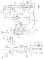
- Atmospheric air 1 is compressed after flowing through a filter 2 (3) and Direct contact cooler 4 initiated. There it comes into countercurrent contact with liquid Water 5.
- the water 6 remaining liquid in the direct heat exchange becomes withdrawn from the direct contact cooler 4.
- the cooled and steamed laden air 7 is in a cleaning device 8 of water and carbon dioxide and optionally freed of further impurities.
- the cleaning facility 8 is preferably formed by at least two switchable containers, which with an adsorbent, for example a molecular sieve.
- the cleaned feed air flow 9 is divided into a first main air flow 10 and one split second main air stream 20.
- the former flows to the warm end of one Main heat exchanger 30 is in the main heat exchanger 30 to about dew point cooled, removed again at the cold end and finally via lines 11 and 12 fed to the bottom of the pressure column 50 of a double column.
- the second main air stream 20 is in an externally driven secondary compressor 21 further compressed and after flowing through an aftercooler 22 also warm End inserted into the main heat exchanger 30 (line 23).
- Part 24 of the second Main air flow the "cooling air flow” remains in the cold end Main heat exchanger 30 and 25 - if necessary after slight throttling "First partial flow" 26 reintroduced into the main heat exchanger 30, namely in the Warm-up passages 17.
- the first partial flow removed via line 28 and fed to a cold compressor 29.
- the cold compacted first partial flow 31 is at a second intermediate temperature, which in the example is higher than the first intermediate temperature, again into the main heat exchanger 30 introduced, namely in the cooling passages 32.
- After cooling and at least partial liquefaction in the main heat exchanger becomes the first partial flow 33 finally fed into the pressure column 50 via the valve 34.
- the feed point is one or more theoretical or practical floors above the Pressure column sump.
- Another part 35 of the second main air stream 23 becomes a third Intermediate temperature, which in the example is between the first and the second Intermediate temperature is taken as "turbine air flow" and one Relaxation machine 36 supplied, which is on a common shaft with the Cold compressor 29 and a generator 37 is coupled.
- the work relaxed Air 38 together with the first main air stream 11 via line 12 to the sump the pressure column 50 out.
- the double column has a low pressure column 51. Both Parts are on a common condenser-evaporator 52, the Main condenser in heat exchanging connection. Top gas 53 of the pressure column 50 is at least partially condensed in the main condenser 52. The condensate flows to a first part 55 as a return to the pressure column 50, to a second part 55 it is subcooled in a supercooling counterflow 56 and via line 57 and valve 58 placed on top of the low pressure column 51.
- Raw oxygen from the lower region of the pressure column 50 flows up in the example two different routes to the low pressure column 51.
- a first raw oxygen fraction 59 is subcooled from the bottom of the pressure column (56) and via line 60 and Throttle valve 61 transferred to the low pressure column.
- At the level of the infeed of the liquefied first partial air stream 33 becomes a second crude oxygen liquid of the pressure column 50 and in a similar manner (subcooling 56, line 63 and valve 64) are fed into the low-pressure column 51 at a somewhat higher point.
- the oxygen product is liquid via line 65 from the bottom of the Low pressure column 51 withdrawn by a pump 66 in the liquid state on the brought desired product pressure, via line 67 to the main heat exchanger 30 led, evaporated there and warmed to about ambient temperature.
- the Oxygen leaves the system via line 68 as an internally compressed product (GOX-IC, gaseous oxygen - internally compressed).
- no pure nitrogen is produced.
- the nitrogen rich Top product 69 is used as residual gas in the supercooling counterflow 56 and in Main heat exchanger 30 warmed up.
- the warm residual gas 70 can be conducted directly via the line 71 can be released into the atmosphere and / or via line 72 - if necessary after heating 73 - used as regeneration gas for the cleaning device 8 become.
- the moist regeneration gas flows via line 74 to the atmosphere.
- Deviating from the embodiment can in the low pressure column on the pure nitrogen can also be obtained in a known manner.
- the evaporation of the liquid pressurized oxygen 67 can also be outside the main heat exchanger 30 is carried out in a separate product evaporator (secondary condenser), whose liquefaction space downstream of the first substream Cold compression 29 is flowed through.
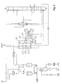
- FIG. 2 corresponds to the method and the device of FIG Figure 1 in large parts. In the following only the different aspects in the described.
- the cooling air stream 24 is downstream of its removal from the cold end the main heat exchanger 30 or the optional valve 25 to two Streams divided, namely the "first sub-stream" 226 - 227 - 228, which is analogous to that 1 to the cold compressor 29, and a "second partial flow" 201, which - regulated by valve 202 - on the main heat exchanger 30 and in particular passed the warm-up passages 227 and at 203 the first Intermediate temperature warmed first partial stream 228 is mixed.
- the Mixture flows at a correspondingly lower temperature at the entry of the Cold compressor 29.
- the cold compressed air 231 also has a lower one Temperature than in Figure 1, in the specific example of Figure 2 is the second Intermediate temperature even lower than the first intermediate temperature.
- Corresponding the cooling and liquefaction passages 232 are shorter for the first one Partial flow downstream of the cold compression.
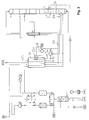
- the cooling air flow 24 is here after partial liquefaction Main heat exchanger 30 and throttling 25 for phase separation into one Separator 301 initiated.
- the liquid phase becomes analogous to stream 33 from FIG. 1 fed into the pressure column 50 via line 333 and valve 334.
- the steam 326 out the separator 301 forms the "first partial flow" which, as in FIG Cold compression 29 is performed. Downstream of the cold compression 29 cold-compressed first partial flow 331, however, not in its own cooling passages introduced, but mixed with the second main air flow.
- the cold compressed The amount of air will thus be circulated in a 24 - 25 - 301 - 326 - 29 - 331 cycle.
- the heat transfer in the cold part of the main heat exchanger can be special be designed cheaply.
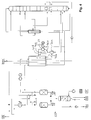
- Figure 4 differs from Figure 3 in the same way, Figure 2 is different from Figure 1, namely by an additional "second partial air flow” 401.
- the admixture 403 of the cold second partial stream is used 401 to the first partial flow 428, which is heated to the first intermediate temperature Compensation or overcompensation of the heat of compression, which at the cold compression 29 arises.
Abstract
Description
Die Erfindung betrifft ein Verfahren zur Tieftemperaturzerlegung von Luft, bei dem verdichtete und gereinigte Einsatzluft in einem Hauptwärmetauscher abgekühlt und mindestens zum Teil einer Rektifiziersäule zugeführt wird, wobei ein erster Teilstrom der Einsatzluft bei einer Zwischentemperatur aus dem Hauptwärmetauscher entnommen und unter dieser Zwischentemperatur einer Kaltverdichtung zugeführt wird.The invention relates to a method for the low-temperature separation of air, in which compressed and cleaned feed air cooled in a main heat exchanger and is supplied at least in part to a rectification column, a first partial stream the feed air at an intermediate temperature from the main heat exchanger removed and fed to a cold compression at this intermediate temperature.
Verfahren und Vorrichtung zur Tieftemperaturzerlegung von Luft sind zum Beispiel aus Hausen/Linde, Tieftemperaturtechnik, 2. Auflage 1985, Kapitel 4 (Seiten 281 bis 337) bekannt.Methods and apparatus for the low-temperature separation of air are, for example, out Hausen / Linde, low-temperature technology, 2nd edition 1985, chapter 4 (pages 281 to 337) known.
Die Erfindung kommt in solchen Fällen zum Einsatz, in denen ein Teil der Einsatzluft ("erster Teilstrom") nachverdichtet wird, beispielsweise um zur Verdampfung eines flüssigen Prozeßstroms eingesetzt zu werden. Bei dem flüssigen Prozeßstrom kann es sich um einen Produktstrom (z.B. flüssigen Sauerstoff, flüssigen Stickstoff oder flüssiges Argon) aus einer Rektifiziersäule, um die Sumpf- oder Zwischenflüssigkeit einer Rektifiziersäule oder auch um eine externe Flüssigkeit handeln, die beispielsweise einem Speichertank entnommen wird. Es ist auch möglich, zwei oder mehr derartige Prozeßströme gegen den nachverdichteten Luftteilstrom zu verdampfen.The invention is used in cases where part of the feed air ("first partial stream") is post-compressed, for example in order to evaporate a liquid process stream to be used. With the liquid process stream, it can a product stream (e.g. liquid oxygen, liquid nitrogen or liquid argon) from a rectification column to the bottom or intermediate liquid a rectification column or an external liquid that for example, is removed from a storage tank. It is also possible to have two or two more such process streams against the post-compressed partial air stream evaporate.
Der "Hauptwärmetauscher" wird vorzugsweise durch einen einzigen Wärmetauscherblock gebildet. Bei größeren Anlagen kann es sinnvoll sein, den Hauptwärmetauscher durch mehrere hinsichtlich es Temperaturverlaufs parallelgeschaltete Stränge zu realisieren, die durch voneinander getrennte Bauelemente gebildet werden. Grundsätzlich ist es möglich, daß der Hauptwärmetauscher beziehungsweise jeder dieser Stränge durch zwei oder mehr seriell verbundene Blöcke gebildet wird.The "main heat exchanger" is preferably replaced by a single one Heat exchanger block formed. In the case of larger systems, it may make sense to use the Main heat exchanger through several in terms of temperature history parallel strands to be realized by separate Components are formed. Basically, it is possible that the Main heat exchanger or each of these strands by two or more serially connected blocks is formed.
In vielen Fällen wird diese Nachverdichtung auf konventionelle Weise durchgeführt, indem der Luftteilstrom bei etwa Umgebungstemperatur einer entsprechenden Maschine zugeführt wird. Alternativ kann ein Kaltverdichter zur Nachverdichtung verwendet werden. Unter "Kaltverdichtung" wird hier ein Verdichtungsvorgang verstanden, bei dem das Gas der Verdichtung bei einer Temperatur zugeführt wird, die deutlich unterhalb der Umgebungstemperatur liegt, im allgemeinen unterhalb von 250 K, vorzugsweise unterhalb von 200 K.In many cases, this densification is carried out in a conventional manner, by the partial air flow at about an ambient temperature of a corresponding Machine is fed. Alternatively, a cold compressor for post-compression be used. Under "cold compression" there is a compression process understood, in which the gas is supplied to the compression at a temperature which is well below ambient temperature, generally below 250 K, preferably below 200 K.
Aus WO 9528610 oder EP 644388 A sind Verfahren bekannt, bei denen die Kaltverdichtung bei einer Zwischentemperatur durchgeführt wird, die zwischen den Temperaturen am warmen und kalten Ende des Hauptwärmetauschers liegt. Diese Zwischentemperatur kann insbesondere an demjenigen Punkt liegen, an dem sich die Kurven der anzuwärmenden und abzukühlenden Ströme im Wärmeaustauschdiagramm (Q-T-Diagramm) des Hauptwärmetauschers am nächsten kommen ("theoretical pinch point").Methods are known from WO 9528610 or EP 644388 A, in which the Cold compression is carried out at an intermediate temperature between the Temperatures at the warm and cold end of the main heat exchanger. This The intermediate temperature can be in particular at the point at which the Curves of the currents to be heated and cooled in the Heat exchange diagram (Q-T diagram) closest to the main heat exchanger come ("theoretical pinch point").
Bei den bekannten Verfahren wird der Luftteilstrom, der zur Kaltverdichtung führt, im Hauptwärmetauscher vom warmen Ende her bis zu der Zwischentemperatur abgekühlt und an der entsprechenden Zwischenstelle des Hauptwärmetauschers unmittelbar aus Abkühlpassagen entnommen.In the known methods, the partial air flow, which leads to cold compression, in the Main heat exchanger cooled from the warm end to the intermediate temperature and directly at the corresponding intermediate point of the main heat exchanger Cooling passages removed.
Der Erfindung liegt die Aufgabe zugrunde, das Verfahren der eingangs genannten Art und eine entsprechende Vorrichtung anzugeben, die energetisch besonders günstig zu betreiben sind.The invention has for its object the method of the type mentioned and to specify a corresponding device that is particularly energetically favorable are operating.
Diese Aufgabe wird dadurch gelöst, daß der erste Teilstrom stromaufwärts seiner Entnahme im Hauptwärmetauscher angewärmt wird.This object is achieved in that the first partial stream upstream of it Removal is heated in the main heat exchanger.
Gemäß der Erfindung wird der für die Kaltverdichtung vorgesehene Luftteilstrom also zunächst weiter als eigentlich nötig im Hauptwärmetauscher abgekühlt, also über die Zwischentemperatur hinaus, die etwa der Eintrittstemperatur der Kaltverdichtung entspricht. Anschließend wird er - ebenfalls im Hauptwärmetauscher - wieder auf die Zwischentemperatur angewärmt. Diese Verfahrensweise erscheint auf den ersten Blick ungünstig, da durch die an sich unnötige Abkühlung und Rückerwärmung mit zusätzlichen Austauschverlusten und damit höherem Energieverbrauch zu rechnen ist. Im Rahmen der Erfindung hat sich jedoch herausgestellt, daß dadurch der Wärmeübergang im kalten Teil des Hauptwärmetauschers (unterhalb der Zwischentemperatur) verbessert wird. According to the invention, the partial air flow provided for the cold compression is thus initially cooled further than is actually necessary in the main heat exchanger, i.e. via the Intermediate temperature, which is about the entry temperature of the cold compression corresponds. Then he - again in the main heat exchanger - on the Intermediate temperature warmed up. This procedure appears at first glance unfavorable, because of the unnecessary cooling and reheating additional exchange losses and thus higher energy consumption can be expected. In the context of the invention, however, it has been found that the Heat transfer in the cold part of the main heat exchanger (below the Intermediate temperature) is improved.
Im kalten Teil des Hauptwärmetauschers weisen die anzuwärmenden und abzukühlenden Ströme nämlich eine höhere Dichte auf als im warmen Teil. Die Wärmetauscherpassagen, die sie durchströmen, haben in der Regel aus konstruktiven Gründen dieselbe Anzahl und dieselben Querschnitte. Die Passagen werden im kalten Teil sozusagen mit einer Unterlast von etwa 20 % betrieben. Aufgrund dieser Tatsache sind die Strömungsverhältnisse im kalten Teil des Hauptwärmetauschers nicht optimal. Die Erfindung erreicht hier eine Verbesserung, indem der - ohnehin speziell zu behandelnde - Luftteilstrom für die Kaltverdichtung sowohl die abzukühlenden, als auch die anzuwärmenden Ströme ergänzt. Es hat sich herausgestellt, daß die Verbesserung des Wärmeübergangs durch die im Rahmen der Erfindung optimierten Strömungsverhältnisse im kalten Teil des Hauptwärmetauschers die erwartungsgemäßen zusätzlichen Austauschverluste überkompensiert und insgesamt zu einen energetisch besonders günstigen Prozeß führt. Außerdem führt der zusätzliche Mengenstrom im kalten Teil des Hauptwärmetauschers zu einem steileren Verlauf der Kurven der anzuwärmenden und abzukühlenden Ströme im Q-T-Diagramm und damit zu einer Verbesserung an der Stelle, an der sich diese Kurven am nächsten kommen ("theoretical pinch point").In the cold part of the main heat exchanger, the ones to be heated and currents to be cooled have a higher density than in the warm part. The Heat exchanger passages that they flow through usually have constructive Establish the same number and the same cross-sections. The passages are cold Part operated with an underload of about 20%, so to speak. Due to this fact the flow conditions in the cold part of the main heat exchanger are not optimal. The invention achieves an improvement here by - specifically anyway treating - partial air flow for cold compression both the ones to be cooled and the currents to be heated are also supplemented. It has been found that the Improvement of the heat transfer through the optimized in the context of the invention Flow conditions in the cold part of the main heat exchanger expected additional exchange losses overcompensated and overall leads to an energetically particularly favorable process. In addition, the additional flow in the cold part of the main heat exchanger to a steeper Course of the curves of the flows to be heated and cooled in the Q-T diagram and thus an improvement at the point where these curves are closest come ("theoretical pinch point").
Der erste Teilstrom kann stromabwärts der Kaltverdichtung gegen einen verdampfenden Prozeßstrom mindestens teilweise verflüssigt werden. Dieser Wärmeaustauschschritt kann entweder im Hauptwärmetauscher oder in einem separaten Kondensator-Verdampfer durchgeführt werden. Besonders günstig ist diese Verfahrensweise, wenn das gesamte Sauerstoffprodukt oder ein großer Teil davon als Flüssigkeit aus der Rektifikation entnommen, in flüssiger Form auf Druck gebracht und schließlich gegen den kaltverdichteten Luftteilstrom verdampft wird. In diesem Fall wird gerade soviel Luft kaltverdichtet, daß durch die Strömungsverhältnisse im kalten Teil des Hauptwärmetauschers durch die erfindungsgemäße Wiederanwärmung dieses Luftteilstroms praktisch optimal sind.The first partial flow can be downstream against the cold compression evaporating process stream are at least partially liquefied. This Heat exchange step can either be in the main heat exchanger or in one separate condenser-evaporator. This is particularly cheap Procedure if all or a large part of the oxygen product as Liquid removed from the rectification, pressurized in liquid form and is finally evaporated against the cold compressed partial air flow. In this case So much air is cold compressed that the flow conditions in the cold part of the main heat exchanger by reheating it according to the invention Partial air flow are practically optimal.
Vorzugsweise wird der erste Teilstrom vor seiner Anwärmung in das kalte Ende des Hauptwärmetauschers eingeführt. Er wird also zunächst vollständig durch den Hauptwärmetauscher geführt und strömt bei seiner Anwärmung nochmals durch den gesamten kalten Teil des Hauptwärmetauschers, so daß der gesamte kalte Teil des Hauptwärmetauschers in den Genuß der verbesserten Durchströmung kommt. Preferably, the first partial stream is heated to the cold end of the Main heat exchanger introduced. So it is completely through the Main heat exchanger guided and flows through the entire cold part of the main heat exchanger, so that the entire cold part of the Main heat exchanger can enjoy the improved flow.
Die Abkühlung des ersten Teilstroms kann dabei separat von oder gemeinsam mit anderen Teilen der Einsatzluft durchgeführt werden. Dazu wird ein Abkühlluftstrom im Hauptwärmetauscher abgekühlt, am kalten Ende des Hauptwärmetauschers entnommen und mindestens zum Teil als erster Teilstrom wieder dem kalten Ende des Hauptwärmetauschers zugeführt.The cooling of the first substream can be carried out separately from or together with other parts of the feed air. For this purpose, a cooling air flow in the Main heat exchanger cooled down, at the cold end of the main heat exchanger removed and at least partly as the first partial flow back to the cold end of the Main heat exchanger supplied.
Bei dem erfindungsgemäßen Verfahren kann es günstig sein, vor der Wiederanwärmung des ersten Teilstroms flüssige Anteile abzutrennen. Hierzu wird der Abkühlluftstrom nach seiner Entnahme aus dem kalten Ende des Hauptwärmetauschers einer Phasentrennung unterworfen, wobei der erste Teilstrom mindestens durch einen Teil der aus der Phasentrennung entnommenen Dampfphase gebildet wird. Vorzugsweise wird der gesamte Dampfanteil aus der Phasentrennung zur Kaltverdichtung geführt, während die abgeschiedene Flüssigkeit in die oder eine der Rektifiziersäulen eingespeist wird, zum Beispiel in die Drucksäule eines Zweisäulenapparats.In the method according to the invention, it may be advantageous to To reheat the first partial stream to separate liquid components. For this, the Cooling air flow after it is removed from the cold end of the Main heat exchanger subjected to phase separation, the first partial flow at least by part of the vapor phase removed from the phase separation is formed. The entire vapor portion is preferably from the phase separation led to cold compression while the separated liquid into or one the rectification columns is fed, for example into the pressure column of a Two-column apparatus.
Insbesondere in diesem Fall ist es günstig, wenn der Abkühlluftstrom entspannt wird, bevor er der Phasentrennung unterworfen wird. Aber auch bei fehlender Phasentrennung kann es sinnvoll sein, den Abkühlluftstrom abzudrosseln, bevor er als erster Teilstrom dem kalten Ende des Hauptwärmetauschers zugeführt wird.In this case in particular, it is advantageous if the cooling air flow is expanded, before being subjected to phase separation. But even if there is no Phase separation, it may be useful to throttle the cooling air flow before using it first partial flow is fed to the cold end of the main heat exchanger.
Grundsätzlich kann der gesamte Strom, der der Kaltverdichtung unterworfen wird, durch den ersten Teilstrom gebildet werden, der an der Zwischenstelle aus dem Hauptwärmetauscher abgezogen wird. In vielen Fällen ist es jedoch günstiger, wenn der Abkühlluftstrom in den ersten Teilstrom und in einen zweiten Teilstrom aufgeteilt wird, wobei der erste Teilstrom in das kalte Ende des Hauptwärmetauschers eingeführt wird und der zweite Teilstrom ohne temperaturverändemde Maßnahmen mit dem ersten Teilstrom zwischen seiner Entnahme bei der ersten Zwischentemperatur und der Kaltverdichtung zugeführt wird. Hierdurch wird zusätzlich Kälte in den Kaltverdichtungsstrom eingeführt, die zur teilweise oder vollständigen Kompensation oder unter Umständen sogar zur Überkompensation bei der Kaltverdichtung erzeugten Kompressionswärme dient. Hiermit erhält man einen zusätzlichen Parameter, der zur Optimierung des Wärmeaustauschprozesses eingesetzt werden kann. Basically, all of the electricity that is subjected to cold compression can are formed by the first partial flow, which at the intermediate point from the Main heat exchanger is withdrawn. In many cases, however, it is cheaper if the cooling air flow is divided into the first partial flow and a second partial flow is introduced, the first partial flow in the cold end of the main heat exchanger and the second partial flow without temperature-changing measures with the first partial flow between its removal at the first intermediate temperature and the cold compression is fed. This will also cause cold in the Cold compression current introduced, for partial or full compensation or possibly even for overcompensation during cold compression Compression heat is used. This gives you an additional parameter that is used for Optimization of the heat exchange process can be used.
Der erste Teilstrom kann stromabwärts der Kaltverdichtung an einer Zwischenstelle des Hauptwärmetauschers, die einer zweiten Zwischentemperatur entspricht, dem Abkühlluftstrom zugeführt werden. Ohne die im vorigen Absatz beschriebene Kompensation der Kompressionswärme liegt diese zweite Zwischentemperatur oberhalb der ersten Zwischentemperatur. Bei Vermischung mit dem sehr kalten zweiten Teilluftstrom stromaufwärts der Kaltverdichtung kann die zweite Zwischentemperatur bei oder sogar unterhalb der ersten Zwischentemperatur liegen.The first partial flow can be downstream of the cold compression at an intermediate point of the main heat exchanger, which corresponds to a second intermediate temperature, the Cooling air flow are supplied. Without the one described in the previous paragraph Compensation for the heat of compression lies at this second intermediate temperature above the first intermediate temperature. When mixed with the very cold second partial air flow upstream of the cold compression, the second Intermediate temperature at or even below the first intermediate temperature.
Es ist außerdem günstig, wenn ein Turbinenluftstrom im Hauptwärmetauscher auf eine dritte Zwischentemperatur abgekühlt und anschließend arbeitsleistend entspannt wird, wobei mindestens eine Teil der bei der arbeitsleistenden Entspannung erzeugten mechanischen Energie zum Antrieb der Kaltverdichtung eingesetzt wird. Falls die für das Verfahren benötigte Kälte nicht durch eine weitere Entspannungsmaschine erzeugt wird, ist es notwendig, die Entspannungsmaschine nicht nur mit dem Kaltverdichter, sondern zusätzlich mit einem Generator oder einem Bremsgebläse zu koppeln.It is also beneficial if a turbine air flow in the main heat exchanger is directed to a the third intermediate temperature is cooled and then relaxed in a work-performing manner, wherein at least a portion of the relaxation generated during work relaxation mechanical energy is used to drive the cold compression. If that's for the process does not require cold to be generated by another expansion machine it is necessary to use the expansion machine not only with the cold compressor, but also to couple with a generator or a brake blower.
Die Erfindung betrifft außerdem eine Vorrichtung zur Tieftemperaturzerlegung von Luft gemäß den Ansprüchen 5 bis 8.The invention also relates to a device for the low-temperature separation of air according to claims 5 to 8.
Die Erfindung sowie weitere Einzelheiten der Erfindung werden im folgenden anhand von in den Zeichnungen schematisch dargestellten Ausführungsbeispielen näher erläutert. Hierbei zeigen:
- Figur 1
- ein erstes Ausführungsbeispiel für die Erfindung,
Figur 2- eine Abwandlung des ersten Ausführungsbeispiels,
Figur 3- ein zweites Ausführungsbeispiel für die Erfindung und
- Figur 4
- eine Abwandlung des zweiten Ausführungsbeispiels.
- Figure 1
- a first embodiment for the invention,
- Figure 2
- a modification of the first embodiment,
- Figure 3
- a second embodiment of the invention and
- Figure 4
- a modification of the second embodiment.
Atmosphärische Luft 1 wird nach Durchströmen eines Filters 2 verdichtet (3) und
Direktkontaktkühler 4 eingeleitet. Sie tritt dort in Gegenstromkontakt mit flüssigem
Wasser 5. Das bei dem direkten Wärmeaustausch flüssig verbliebene Wasser 6 wird
aus dem Direktkontaktkühler 4 abgezogen. Die abgekühlte und mit Wasserdampf
beladene Luft 7 wird in einer Reinigungseinrichtung 8 von Wasser und Kohlendioxid
und gegebenenfalls von weiteren Verunreinigungen befreit. Die Reinigungseinrichtung
8 wird vorzugsweise durch mindestens zwei umschaltbare Behälter gebildet, die mit
einem Adsorbens, beispielsweise einem Molekularsieb gefüllt sind.Atmospheric air 1 is compressed after flowing through a filter 2 (3) and
Direct contact cooler 4 initiated. There it comes into countercurrent contact with liquid
Water 5. The water 6 remaining liquid in the direct heat exchange becomes
withdrawn from the direct contact cooler 4. The cooled and steamed
Der gereinigte Einsatzluftstrom 9 wird in einen ersten Hauptluftstrom 10 und einen
zweiten Hauptluftstrom 20 aufgeteilt. Ersterer strömt zum warmen Ende eines
Hauptwärmetauschers 30, wird im Hauptwärmetauscher 30 auf etwa Taupunkt
abgekühlt, am kalten Ende wieder entnommen und schließlich über die Leitungen 11
und 12 dem Sumpf der Drucksäule 50 einer Doppelsäule zugeleitet.The cleaned feed air flow 9 is divided into a first
Der zweite Hauptluftstrom 20 wird in einem extern angetriebenen Nachverdichter 21
weiter verdichtet und nach Durchströmen eines Nachkühlers 22 ebenfalls am warmen
Ende in den Hauptwärmetauscher 30 eingeführt (Leitung 23). Ein Teil 24 des zweiten
Hauptluftstroms, der "Abkühlluftstrom" verbleibt bis zum kalten Ende im
Hauptwärmetauscher 30 und wird - gegebenenfalls nach leichter Drosselung 25 als
"erster Teilstrom" 26 wieder in den Hauptwärmetauscher 30 eingeleitet, und zwar in die
Anwärmpassagen 17. Bei einer ersten Zwischentemperatur wird der erste Teilstrom
über Leitung 28 entnommen und einem Kaltverdichter 29 zugeführt. Der kaltverdichtete
erste Teilstrom 31 wird bei einer zweiten Zwischentemperatur, die in dem Beispiel
höher als die erste Zwischentemperatur ist, wieder in den Hauptwärmetauscher 30
eingeführt, und zwar in die Abkühlpassagen 32. Nach Abkühlung und mindestens
teilweiser Verflüssigung im Hauptwärmetauscher wird der erste Teilstrom 33
schließlich über das Ventil 34 in die Drucksäule 50 eingespeist. Die Einspeisestelle
liegt einen oder mehrere theoretische beziehungsweise praktische Böden oberhalb des
Drucksäulensumpfs.The second main air stream 20 is in an externally driven
Ein anderer Teil 35 des zweiten Hauptluftstroms 23 wird bei einer dritten
Zwischentemperatur, die in dem Beispiel zwischen der ersten und der zweiten
Zwischentemperatur liegt, als "Turbinenluftstrom" entnommen und einer
Entspannungsmaschine 36 zugeführt, die über eine gemeinsame Welle mit dem
Kaltverdichter 29 und einem Generator 37 gekoppelt ist. Die arbeitsleistend entspannte
Luft 38 wird gemeinsam mit dem ersten Hauptluftstrom 11 über Leitung 12 zum Sumpf
der Drucksäule 50 geführt.Another part 35 of the second
Die Doppelsäule weist außer der Drucksäule 50 eine Niederdrucksäule 51 auf. Beide
Teile stehen über einen gemeinsamen Kondensator-Verdampfer 52, den
Hauptkondensator in wärmetauschender Verbindung. Kopfgas 53 der Drucksäule 50
wird im Hauptkondensator 52 mindestens teilweise kondensiert. Das Kondensat strömt
zu einem ersten Teil 55 als Rücklauf zur Drucksäule 50 zurück, zu einem zweiten Teil
55 wird es in einem Unterkühlungsgegenströmer 56 unterkühlt und über Leitung 57
und Ventil 58 auf den Kopf der Niederdrucksäule 51 aufgegeben.In addition to the pressure column 50, the double column has a low pressure column 51. Both
Parts are on a common condenser-evaporator 52, the
Main condenser in heat exchanging connection. Top gas 53 of the pressure column 50
is at least partially condensed in the main condenser 52. The condensate flows
to a
Rohsauerstoff aus dem unteren Bereich der Drucksäule 50 strömt in dem Beispiel auf
zwei verschiedenen Wegen zur Niederdrucksäule 51. Eine erste Rohsauerstofffraktion
59 wird vom Sumpf der Drucksäule wird unterkühlt (56) und über Leitung 60 und
Drosselventil 61 in die Niederdrucksäule überführt. Auf Höhe der Einspeisung des
verflüssigten ersten Teilluftstroms 33 wird eine zweite Rohsauerstofffraktion flüssig aus
der Drucksäule 50 abgeführt und auf ähnliche Weise (Unterkühlung 56, Leitung 63
und Ventil 64) an etwas höherer Stelle in die Niederdrucksäule 51 eingespeist.Raw oxygen from the lower region of the pressure column 50 flows up in the example
two different routes to the low pressure column 51. A first
Das Sauerstoffprodukt wird über Leitung 65 flüssig aus dem Sumpf der
Niederdrucksäule 51 abgezogen, durch eine Pumpe 66 in flüssigem Zustand auf den
gewünschten Produktdruck gebracht, über Leitung 67 zum Hauptwärmetauscher 30
geführt, dort verdampft und auf etwa Umgebungstemperatur angewärmt. Der
Sauerstoff verläßt die Anlage über Leitung 68 als innenverdichtetes Produkt (GOX-IC,
gaseous oxygen - intemally compressed).The oxygen product is liquid via
In dem Ausführungsbeispiel wird kein reiner Stickstoff hergestellt. Das stickstoffreiche
Kopfprodukt 69 wird als Restgas im Unterkühlungsgegenströmer 56 und im
Hauptwärmetauscher 30 angewärmt. Das warme Restgas 70 kann direkt über Leitung
71 in die Atmosphäre abgelassen werden und/oder über Leitung 72 - gegebenenfalls
nach Erhitzen 73 - als Regeneriergas für die Reinigungseinrichtung 8 verwendet
werden. Das feuchte Regeneriergas strömt über Leitung 74 zur Atmosphäre.In the exemplary embodiment, no pure nitrogen is produced. The nitrogen rich
Abweichend von dem Ausführungsbeispiel kann in der Niederdrucksäule auf die
bekannte Weise auch reiner Stickstoff gewonnen werden. Die Verdampfung des flüssig
auf Druck gebrachten Sauerstoffs 67 kann auch außerhalb des Hauptwärmetauschers
30 in einem separaten Produktverdampfer (Nebenkondensator) durchgeführt wird,
dessen Verflüssigungsraum von dem ersten Teilstrom stromabwärts der
Kaltverdichtung 29 durchströmt wird. Deviating from the embodiment can in the low pressure column on the
pure nitrogen can also be obtained in a known manner. The evaporation of the liquid
Das Ausführungsbeispiel der Figur 2 entspricht dem Verfahren und der Vorrichtung von Figur 1 in weiten Teilen. Im folgenden werden lediglich die abweichenden Aspekte im einzelnen beschrieben.The exemplary embodiment in FIG. 2 corresponds to the method and the device of FIG Figure 1 in large parts. In the following only the different aspects in the described.
In Figur 2 wird der Abkühlluftstrom 24 stromabwärts seiner Entnahme vom kalten Ende
des Hauptwärmetauschers 30 beziehungsweise des optionalen Ventils 25 auf zwei
Ströme aufgeteilt, nämlich den "ersten Teilstrom" 226 - 227 - 228, der analog zu dem
Verfahren von Figur 1 zum Kaltverdichter 29 geführt wird, und eine "zweiten Teilstrom"
201, der - geregelt von Ventil 202 - am Hauptwärmetauscher 30 und insbesondere an
den Anwärmpassagen 227 vorbeigeleitet und bei 203 dem auf die erste
Zwischentemperatur angewärmten ersten Teilstrom 228 zugemischt wird. Das
Gemisch strömt unter einer entsprechend niedrigeren Temperatur zum Eintritt des
Kaltverdichters 29. Demzufolge weist auch die kaltverdichtete Luft 231 eine niedrigere
Temperatur als bei Figur 1 auf, in dem konkreten Beispiel von Figur 2 ist die zweite
Zwischentemperatur sogar geringer als die erste Zwischentemperatur. Entsprechend
kürzer ausgebildet sind die Abkühl- und Verflüssigungspassagen 232 für den ersten
Teilstrom stromabwärts der Kaltverdichtung.In Figure 2, the cooling air stream 24 is downstream of its removal from the cold end
the
Auch bezüglich Figur 3 werden im folgenden lediglich die Unterschiede zu Figur 1
detailliert besprochen. Der Abkühlluftstrom 24 wird hier nach Teilverflüssigung im
Hauptwärmetauscher 30 und Drosselung 25 zwecks Phasentrennung in einen
Abscheider 301 eingeleitet. Die flüssige Phase wird analog zum Strom 33 von Figur 1
über Leitung 333 und Ventil 334 in die Drucksäule 50 eingespeist. Der Dampf 326 aus
dem Abscheider 301 bildet den "ersten Teilstrom", der wie in Figur 1 zur
Kaltverdichtung 29 geführt wird. Stromabwärts der Kaltverdichtung 29 wird der
kaltverdichtete erste Teilstrom 331 allerdings nicht in eigene Abkühlpassagen
eingeführt, sondern mit dem zweiten Hauptluftstrom vermischt. Die kaltverdichtete
Luftmenge wird somit in einem Kreislauf 24 - 25 - 301 - 326 - 29 - 331 geführt werden.
Somit kann der Wärmeübergang im kalten Teil des Hauptwärmetauschers besonders
günstig gestaltet werden.3, only the differences from FIG. 1 are also described below
discussed in detail. The cooling air flow 24 is here after partial liquefaction
Figur 4 unterscheidet sich auf dieselbe Weise von Figur 3 wird Figur 2 von Figur 1,
nämlich durch einen zusätzlichen "zweiten Teilluftstrom" 401. Dieser wird hier aus
demjenigen Teil 401 des Dampfs aus dem Abscheider 301 gebildet wird, der nicht über
Leitung 426 als "erster Teilstrom" zum kalten Ende des Hauptwärmetauschers 30
geleitet wird. Wie in Figur 2 dient die Zumischung 403 des kalten zweiten Teilstroms
401 zum auf die erste Zwischentemperatur angewärmten ersten Teilstrom 428 der
Kompensation beziehungsweise Überkompensation der Kompressionswärme, die bei
der Kaltverdichtung 29 entsteht.Figure 4 differs from Figure 3 in the same way, Figure 2 is different from Figure 1,
namely by an additional "second partial air flow" 401. This becomes here
that
Claims (10)
Applications Claiming Priority (2)
| Application Number | Priority Date | Filing Date | Title |
|---|---|---|---|
| DE19930731 | 1999-07-05 | ||
| DE19930731 | 1999-07-05 |
Publications (2)
| Publication Number | Publication Date |
|---|---|
| EP1067345A1 true EP1067345A1 (en) | 2001-01-10 |
| EP1067345B1 EP1067345B1 (en) | 2004-06-16 |
Family
ID=7913552
Family Applications (1)
| Application Number | Title | Priority Date | Filing Date |
|---|---|---|---|
| EP99121174A Expired - Lifetime EP1067345B1 (en) | 1999-07-05 | 1999-10-22 | Process and device for cryogenic air separation |
Country Status (4)
| Country | Link |
|---|---|
| US (1) | US6336345B1 (en) |
| EP (1) | EP1067345B1 (en) |
| AT (1) | ATE269526T1 (en) |
| DE (1) | DE59909750D1 (en) |
Cited By (21)
| Publication number | Priority date | Publication date | Assignee | Title |
|---|---|---|---|---|
| WO2007145915A2 (en) * | 2006-06-09 | 2007-12-21 | Praxair Technology Inc. | Air separation method |
| DE102007031759A1 (en) | 2007-07-07 | 2009-01-08 | Linde Ag | Method and apparatus for producing gaseous pressure product by cryogenic separation of air |
| DE102007031765A1 (en) | 2007-07-07 | 2009-01-08 | Linde Ag | Process for the cryogenic separation of air |
| DE102009034979A1 (en) | 2009-04-28 | 2010-11-04 | Linde Aktiengesellschaft | Method for producing pressurized oxygen by evaporating liquid oxygen using a copper and nickel heat exchanger block |
| EP2312248A1 (en) | 2009-10-07 | 2011-04-20 | Linde Aktiengesellschaft | Method and device for obtaining pressurised oxygen and krypton/xenon |
| EP2458311A1 (en) | 2010-11-25 | 2012-05-30 | Linde Aktiengesellschaft | Method and device for creating a gaseous, pressurised product by the cryogenic decomposition of air |
| DE102010052544A1 (en) | 2010-11-25 | 2012-05-31 | Linde Ag | Process for obtaining a gaseous product by cryogenic separation of air |
| EP2520886A1 (en) | 2011-05-05 | 2012-11-07 | Linde AG | Method and device for creating gaseous oxygen pressurised product by the cryogenic decomposition of air |
| EP2568242A1 (en) | 2011-09-08 | 2013-03-13 | Linde Aktiengesellschaft | Method and device for generating of steel |
| EP2600090A1 (en) | 2011-12-01 | 2013-06-05 | Linde Aktiengesellschaft | Method and device for generating pressurised oxygen by cryogenic decomposition of air |
| DE102011121314A1 (en) | 2011-12-16 | 2013-06-20 | Linde Aktiengesellschaft | Method for producing gaseous oxygen product in main heat exchanger system in distillation column system, involves providing turbines, where one of turbines drives compressor, and other turbine drives generator |
| DE102013017590A1 (en) | 2013-10-22 | 2014-01-02 | Linde Aktiengesellschaft | Method for recovering methane-poor fluids in liquid air separation system to manufacture air product, involves vaporizing oxygen, krypton and xenon containing sump liquid in low pressure column by using multi-storey bath vaporizer |
| DE102012017488A1 (en) | 2012-09-04 | 2014-03-06 | Linde Aktiengesellschaft | Method for building air separation plant, involves selecting air separation modules on basis of product specification of module set with different air pressure requirements |
| EP2784420A1 (en) | 2013-03-26 | 2014-10-01 | Linde Aktiengesellschaft | Method for air separation and air separation plant |
| WO2014154339A2 (en) | 2013-03-26 | 2014-10-02 | Linde Aktiengesellschaft | Method for air separation and air separation plant |
| EP2801777A1 (en) | 2013-05-08 | 2014-11-12 | Linde Aktiengesellschaft | Air separation plant with main compressor drive |
| EP2963369A1 (en) | 2014-07-05 | 2016-01-06 | Linde Aktiengesellschaft | Method and device for the cryogenic decomposition of air |
| EP2963371A1 (en) | 2014-07-05 | 2016-01-06 | Linde Aktiengesellschaft | Method and device for creating a pressurised gas product by the cryogenic decomposition of air |
| EP2963367A1 (en) | 2014-07-05 | 2016-01-06 | Linde Aktiengesellschaft | Method and device for cryogenic air separation with variable power consumption |
| EP2963370A1 (en) | 2014-07-05 | 2016-01-06 | Linde Aktiengesellschaft | Method and device for the cryogenic decomposition of air |
| CN109737689A (en) * | 2018-12-29 | 2019-05-10 | 侨源气体(福州)有限公司 | Air separation and purification system and method |
Families Citing this family (9)
| Publication number | Priority date | Publication date | Assignee | Title |
|---|---|---|---|---|
| FR2851330B1 (en) * | 2003-02-13 | 2006-01-06 | Air Liquide | PROCESS AND PLANT FOR THE PRODUCTION OF A GASEOUS AND HIGH PRESSURE PRODUCTION OF AT LEAST ONE FLUID SELECTED AMONG OXYGEN, ARGON AND NITROGEN BY CRYOGENIC DISTILLATION OF AIR |
| FR2854683B1 (en) * | 2003-05-05 | 2006-09-29 | Air Liquide | METHOD AND INSTALLATION FOR PRODUCING PRESSURIZED AIR GASES BY AIR CRYOGENIC DISTILLATION |
| EP1767884A1 (en) * | 2005-09-23 | 2007-03-28 | L'Air Liquide Société Anon. à Directoire et Conseil de Surveillance pour l'Etude et l'Exploitation des Procédés Georges Claude | Process and apparatus for the separation of air by cryogenic distillation |
| EP1972875A1 (en) * | 2007-03-23 | 2008-09-24 | L'AIR LIQUIDE, S.A. pour l'étude et l'exploitation des procédés Georges Claude | Process and apparatus for the separation of air by cryogenic distillation |
| DE102009048456A1 (en) * | 2009-09-21 | 2011-03-31 | Linde Aktiengesellschaft | Method and apparatus for the cryogenic separation of air |
| EP2369281A1 (en) * | 2010-03-09 | 2011-09-28 | Linde Aktiengesellschaft | Method and device for cryogenic decomposition of air |
| DE102010055448A1 (en) | 2010-12-21 | 2012-06-21 | Linde Ag | Method and apparatus for the cryogenic separation of air |
| FR3062197B3 (en) * | 2017-05-24 | 2019-05-10 | Air Liquide | METHOD AND APPARATUS FOR SEPARATING AIR BY CRYOGENIC DISTILLATION |
| WO2021016756A1 (en) * | 2019-07-26 | 2021-02-04 | L'air Liquide, Societe Anonyme Pour L'etude Et L'exploitation Des Procedes Georges Claude | Process and apparatus for the separation of air by cryogenic distillation |
Citations (5)
| Publication number | Priority date | Publication date | Assignee | Title |
|---|---|---|---|---|
| US4224045A (en) * | 1978-08-23 | 1980-09-23 | Union Carbide Corporation | Cryogenic system for producing low-purity oxygen |
| WO1995028610A1 (en) * | 1994-04-15 | 1995-10-26 | L'air Liquide, Societe Anonyme Pour L'etude Et L'exploitation Des Procedes Georges Claude | Improved heat exchanger with brazed plates |
| EP0689019A1 (en) * | 1994-06-20 | 1995-12-27 | L'air Liquide, Societe Anonyme Pour L'etude Et L'exploitation Des Procedes Georges Claude | Process and apparatus for producing gaseous oxygen under pressure |
| EP0831285A2 (en) * | 1996-09-20 | 1998-03-25 | The BOC Group plc | Air separation |
| EP0932003A2 (en) * | 1998-01-22 | 1999-07-28 | Air Products And Chemicals, Inc. | Elevated pressure air separation process with use of waste expansion for compression of a process stream |
Family Cites Families (4)
| Publication number | Priority date | Publication date | Assignee | Title |
|---|---|---|---|---|
| GB2080929B (en) * | 1980-07-22 | 1984-02-08 | Air Prod & Chem | Producing gaseous oxygen |
| US5275003A (en) * | 1992-07-20 | 1994-01-04 | Air Products And Chemicals, Inc. | Hybrid air and nitrogen recycle liquefier |
| FR2714721B1 (en) * | 1993-12-31 | 1996-02-16 | Air Liquide | Method and installation for liquefying a gas. |
| US5901576A (en) * | 1998-01-22 | 1999-05-11 | Air Products And Chemicals, Inc. | Single expander and a cold compressor process to produce oxygen |
-
1999
- 1999-10-22 EP EP99121174A patent/EP1067345B1/en not_active Expired - Lifetime
- 1999-10-22 DE DE59909750T patent/DE59909750D1/en not_active Expired - Fee Related
- 1999-10-22 AT AT99121174T patent/ATE269526T1/en not_active IP Right Cessation
-
2000
- 2000-07-03 US US09/609,762 patent/US6336345B1/en not_active Expired - Fee Related
Patent Citations (5)
| Publication number | Priority date | Publication date | Assignee | Title |
|---|---|---|---|---|
| US4224045A (en) * | 1978-08-23 | 1980-09-23 | Union Carbide Corporation | Cryogenic system for producing low-purity oxygen |
| WO1995028610A1 (en) * | 1994-04-15 | 1995-10-26 | L'air Liquide, Societe Anonyme Pour L'etude Et L'exploitation Des Procedes Georges Claude | Improved heat exchanger with brazed plates |
| EP0689019A1 (en) * | 1994-06-20 | 1995-12-27 | L'air Liquide, Societe Anonyme Pour L'etude Et L'exploitation Des Procedes Georges Claude | Process and apparatus for producing gaseous oxygen under pressure |
| EP0831285A2 (en) * | 1996-09-20 | 1998-03-25 | The BOC Group plc | Air separation |
| EP0932003A2 (en) * | 1998-01-22 | 1999-07-28 | Air Products And Chemicals, Inc. | Elevated pressure air separation process with use of waste expansion for compression of a process stream |
Cited By (29)
| Publication number | Priority date | Publication date | Assignee | Title |
|---|---|---|---|---|
| WO2007145915A2 (en) * | 2006-06-09 | 2007-12-21 | Praxair Technology Inc. | Air separation method |
| US7549301B2 (en) | 2006-06-09 | 2009-06-23 | Praxair Technology, Inc. | Air separation method |
| WO2007145915A3 (en) * | 2006-06-09 | 2009-03-05 | Praxair Technology Inc | Air separation method |
| EP2015012A2 (en) | 2007-07-07 | 2009-01-14 | Linde Aktiengesellschaft | Process for the cryogenic separation of air |
| EP2015013A2 (en) | 2007-07-07 | 2009-01-14 | Linde Aktiengesellschaft | Process and device for producing a gaseous pressurised product by cryogenic separation of air |
| DE102007031765A1 (en) | 2007-07-07 | 2009-01-08 | Linde Ag | Process for the cryogenic separation of air |
| DE102007031759A1 (en) | 2007-07-07 | 2009-01-08 | Linde Ag | Method and apparatus for producing gaseous pressure product by cryogenic separation of air |
| DE102009034979A1 (en) | 2009-04-28 | 2010-11-04 | Linde Aktiengesellschaft | Method for producing pressurized oxygen by evaporating liquid oxygen using a copper and nickel heat exchanger block |
| EP2312248A1 (en) | 2009-10-07 | 2011-04-20 | Linde Aktiengesellschaft | Method and device for obtaining pressurised oxygen and krypton/xenon |
| EP2458311A1 (en) | 2010-11-25 | 2012-05-30 | Linde Aktiengesellschaft | Method and device for creating a gaseous, pressurised product by the cryogenic decomposition of air |
| DE102010052545A1 (en) | 2010-11-25 | 2012-05-31 | Linde Aktiengesellschaft | Method and apparatus for recovering a gaseous product by cryogenic separation of air |
| DE102010052544A1 (en) | 2010-11-25 | 2012-05-31 | Linde Ag | Process for obtaining a gaseous product by cryogenic separation of air |
| EP2466236A1 (en) | 2010-11-25 | 2012-06-20 | Linde Aktiengesellschaft | Method and device for creating a gaseous, pressurised product by the cryogenic decomposition of air |
| EP2520886A1 (en) | 2011-05-05 | 2012-11-07 | Linde AG | Method and device for creating gaseous oxygen pressurised product by the cryogenic decomposition of air |
| EP2568242A1 (en) | 2011-09-08 | 2013-03-13 | Linde Aktiengesellschaft | Method and device for generating of steel |
| DE102011112909A1 (en) | 2011-09-08 | 2013-03-14 | Linde Aktiengesellschaft | Process and apparatus for recovering steel |
| EP2600090A1 (en) | 2011-12-01 | 2013-06-05 | Linde Aktiengesellschaft | Method and device for generating pressurised oxygen by cryogenic decomposition of air |
| DE102011121314A1 (en) | 2011-12-16 | 2013-06-20 | Linde Aktiengesellschaft | Method for producing gaseous oxygen product in main heat exchanger system in distillation column system, involves providing turbines, where one of turbines drives compressor, and other turbine drives generator |
| DE102012017488A1 (en) | 2012-09-04 | 2014-03-06 | Linde Aktiengesellschaft | Method for building air separation plant, involves selecting air separation modules on basis of product specification of module set with different air pressure requirements |
| EP2784420A1 (en) | 2013-03-26 | 2014-10-01 | Linde Aktiengesellschaft | Method for air separation and air separation plant |
| WO2014154339A2 (en) | 2013-03-26 | 2014-10-02 | Linde Aktiengesellschaft | Method for air separation and air separation plant |
| EP2801777A1 (en) | 2013-05-08 | 2014-11-12 | Linde Aktiengesellschaft | Air separation plant with main compressor drive |
| DE102013017590A1 (en) | 2013-10-22 | 2014-01-02 | Linde Aktiengesellschaft | Method for recovering methane-poor fluids in liquid air separation system to manufacture air product, involves vaporizing oxygen, krypton and xenon containing sump liquid in low pressure column by using multi-storey bath vaporizer |
| EP2963369A1 (en) | 2014-07-05 | 2016-01-06 | Linde Aktiengesellschaft | Method and device for the cryogenic decomposition of air |
| EP2963371A1 (en) | 2014-07-05 | 2016-01-06 | Linde Aktiengesellschaft | Method and device for creating a pressurised gas product by the cryogenic decomposition of air |
| EP2963367A1 (en) | 2014-07-05 | 2016-01-06 | Linde Aktiengesellschaft | Method and device for cryogenic air separation with variable power consumption |
| EP2963370A1 (en) | 2014-07-05 | 2016-01-06 | Linde Aktiengesellschaft | Method and device for the cryogenic decomposition of air |
| WO2016005031A1 (en) | 2014-07-05 | 2016-01-14 | Linde Aktiengesellschaft | Method and device for the low-temperature separation of air at variable energy consumption |
| CN109737689A (en) * | 2018-12-29 | 2019-05-10 | 侨源气体(福州)有限公司 | Air separation and purification system and method |
Also Published As
| Publication number | Publication date |
|---|---|
| DE59909750D1 (en) | 2004-07-22 |
| EP1067345B1 (en) | 2004-06-16 |
| US6336345B1 (en) | 2002-01-08 |
| ATE269526T1 (en) | 2004-07-15 |
Similar Documents
| Publication | Publication Date | Title |
|---|---|---|
| EP1067345B1 (en) | Process and device for cryogenic air separation | |
| EP0093448B1 (en) | Process and apparatus for obtaining gaseous oxygen at elevated pressure | |
| EP1134525B1 (en) | Process for producing gaseous and liquid nitrogen with a variable quantity of liquid | |
| DE3706733C2 (en) | ||
| EP1284404A1 (en) | Process and device for recovering a product under pressure by cryogenic air separation | |
| EP1994344A1 (en) | Method and apparatus for fractionating air at low temperatures | |
| DE19803437A1 (en) | Oxygen and nitrogen extracted by low-temperature fractional distillation | |
| EP1074805B1 (en) | Process for producing oxygen under pressure and device therefor | |
| DE10013073A1 (en) | Low temperature separation of air in distillation column system uses integrated heat exchanger system for cooling e.g. air supply by indirect heat exchange during vaporization of first liquid fraction | |
| EP0948730B1 (en) | Method and device for producing compressed nitrogen | |
| DE102010052545A1 (en) | Method and apparatus for recovering a gaseous product by cryogenic separation of air | |
| EP2313724A2 (en) | Process and device for cryogenic air fractionation | |
| DE19609490A1 (en) | Oxygen-production process with reduced energy requirement | |
| EP2963369B1 (en) | Method and device for the cryogenic decomposition of air | |
| DE19951521A1 (en) | Recovering pressurized product by low temperature decomposition of air in rectification system comprises cold compressing heat carrier stream before introducing into mixing column | |
| EP0768503B1 (en) | Triple column air separation process | |
| EP1227288A1 (en) | System with three columns for cryogenic separation of air | |
| EP3019804A2 (en) | Method for producing at least one air product, air separation system, method and device for producing electrical energy | |
| EP0878677A1 (en) | Process and apparatus for the production of nitrogen by cryogenic air separation | |
| DE10052180A1 (en) | Three-column system for the low-temperature separation of air | |
| DE10045128A1 (en) | Method and device for producing high-purity nitrogen by low-temperature air separation | |
| EP1134524A2 (en) | Process for producing gaseous nitrogen | |
| EP1284403B1 (en) | Process and apparatus for the production of oxygen by low temperature air separation | |
| EP2863156A1 (en) | Method for obtaining at least one air product in an air processing system and air processing system | |
| EP1189002A1 (en) | Process and apparatus for obtaining a gaseous product from cryogenic air separation |
Legal Events
| Date | Code | Title | Description |
|---|---|---|---|
| PUAI | Public reference made under article 153(3) epc to a published international application that has entered the european phase |
Free format text: ORIGINAL CODE: 0009012 |
|
| AK | Designated contracting states |
Kind code of ref document: A1 Designated state(s): AT BE CH CY DE DK ES FI FR GB GR IE IT LI LU MC NL PT SE |
|
| AX | Request for extension of the european patent |
Free format text: AL;LT;LV;MK;RO;SI |
|
| 17P | Request for examination filed |
Effective date: 20010612 |
|
| R17P | Request for examination filed (corrected) |
Effective date: 20010601 |
|
| AKX | Designation fees paid |
Free format text: AT BE CH CY DE DK ES FI FR GB GR IE IT LI LU MC NL PT SE |
|
| 17Q | First examination report despatched |
Effective date: 20021126 |
|
| GRAP | Despatch of communication of intention to grant a patent |
Free format text: ORIGINAL CODE: EPIDOSNIGR1 |
|
| GRAS | Grant fee paid |
Free format text: ORIGINAL CODE: EPIDOSNIGR3 |
|
| GRAA | (expected) grant |
Free format text: ORIGINAL CODE: 0009210 |
|
| AK | Designated contracting states |
Kind code of ref document: B1 Designated state(s): AT BE CH CY DE DK ES FI FR GB GR IE IT LI LU MC NL PT SE |
|
| PG25 | Lapsed in a contracting state [announced via postgrant information from national office to epo] |
Ref country code: IE Free format text: LAPSE BECAUSE OF FAILURE TO SUBMIT A TRANSLATION OF THE DESCRIPTION OR TO PAY THE FEE WITHIN THE PRESCRIBED TIME-LIMIT Effective date: 20040616 Ref country code: FR Free format text: LAPSE BECAUSE OF NON-PAYMENT OF DUE FEES Effective date: 20040616 Ref country code: FI Free format text: LAPSE BECAUSE OF FAILURE TO SUBMIT A TRANSLATION OF THE DESCRIPTION OR TO PAY THE FEE WITHIN THE PRESCRIBED TIME-LIMIT Effective date: 20040616 Ref country code: CY Free format text: LAPSE BECAUSE OF FAILURE TO SUBMIT A TRANSLATION OF THE DESCRIPTION OR TO PAY THE FEE WITHIN THE PRESCRIBED TIME-LIMIT Effective date: 20040616 |
|
| REG | Reference to a national code |
Ref country code: GB Ref legal event code: FG4D Free format text: NOT ENGLISH |
|
| REG | Reference to a national code |
Ref country code: CH Ref legal event code: EP |
|
| REF | Corresponds to: |
Ref document number: 59909750 Country of ref document: DE Date of ref document: 20040722 Kind code of ref document: P |
|
| REG | Reference to a national code |
Ref country code: IE Ref legal event code: FG4D Free format text: GERMAN |
|
| GBT | Gb: translation of ep patent filed (gb section 77(6)(a)/1977) |
Effective date: 20040823 |
|
| PG25 | Lapsed in a contracting state [announced via postgrant information from national office to epo] |
Ref country code: GR Free format text: LAPSE BECAUSE OF FAILURE TO SUBMIT A TRANSLATION OF THE DESCRIPTION OR TO PAY THE FEE WITHIN THE PRESCRIBED TIME-LIMIT Effective date: 20040916 Ref country code: DK Free format text: LAPSE BECAUSE OF FAILURE TO SUBMIT A TRANSLATION OF THE DESCRIPTION OR TO PAY THE FEE WITHIN THE PRESCRIBED TIME-LIMIT Effective date: 20040916 |
|
| PG25 | Lapsed in a contracting state [announced via postgrant information from national office to epo] |
Ref country code: ES Free format text: LAPSE BECAUSE OF FAILURE TO SUBMIT A TRANSLATION OF THE DESCRIPTION OR TO PAY THE FEE WITHIN THE PRESCRIBED TIME-LIMIT Effective date: 20040927 |
|
| PGFP | Annual fee paid to national office [announced via postgrant information from national office to epo] |
Ref country code: NL Payment date: 20041003 Year of fee payment: 6 |
|
| PGFP | Annual fee paid to national office [announced via postgrant information from national office to epo] |
Ref country code: SE Payment date: 20041006 Year of fee payment: 6 |
|
| REG | Reference to a national code |
Ref country code: SE Ref legal event code: TRGR |
|
| PGFP | Annual fee paid to national office [announced via postgrant information from national office to epo] |
Ref country code: DE Payment date: 20041014 Year of fee payment: 6 |
|
| PGFP | Annual fee paid to national office [announced via postgrant information from national office to epo] |
Ref country code: GB Payment date: 20041020 Year of fee payment: 6 |
|
| PG25 | Lapsed in a contracting state [announced via postgrant information from national office to epo] |
Ref country code: LU Free format text: LAPSE BECAUSE OF NON-PAYMENT OF DUE FEES Effective date: 20041022 Ref country code: AT Free format text: LAPSE BECAUSE OF NON-PAYMENT OF DUE FEES Effective date: 20041022 |
|
| PG25 | Lapsed in a contracting state [announced via postgrant information from national office to epo] |
Ref country code: MC Free format text: LAPSE BECAUSE OF NON-PAYMENT OF DUE FEES Effective date: 20041031 Ref country code: LI Free format text: LAPSE BECAUSE OF NON-PAYMENT OF DUE FEES Effective date: 20041031 Ref country code: CH Free format text: LAPSE BECAUSE OF NON-PAYMENT OF DUE FEES Effective date: 20041031 |
|
| PGFP | Annual fee paid to national office [announced via postgrant information from national office to epo] |
Ref country code: BE Payment date: 20041216 Year of fee payment: 6 |
|
| REG | Reference to a national code |
Ref country code: IE Ref legal event code: FD4D |
|
| PLBE | No opposition filed within time limit |
Free format text: ORIGINAL CODE: 0009261 |
|
| STAA | Information on the status of an ep patent application or granted ep patent |
Free format text: STATUS: NO OPPOSITION FILED WITHIN TIME LIMIT |
|
| 26N | No opposition filed |
Effective date: 20050317 |
|
| EN | Fr: translation not filed | ||
| REG | Reference to a national code |
Ref country code: CH Ref legal event code: PL |
|
| PG25 | Lapsed in a contracting state [announced via postgrant information from national office to epo] |
Ref country code: IT Free format text: LAPSE BECAUSE OF NON-PAYMENT OF DUE FEES Effective date: 20051022 Ref country code: GB Free format text: LAPSE BECAUSE OF NON-PAYMENT OF DUE FEES Effective date: 20051022 |
|
| PG25 | Lapsed in a contracting state [announced via postgrant information from national office to epo] |
Ref country code: SE Free format text: LAPSE BECAUSE OF NON-PAYMENT OF DUE FEES Effective date: 20051023 |
|
| PG25 | Lapsed in a contracting state [announced via postgrant information from national office to epo] |
Ref country code: BE Free format text: LAPSE BECAUSE OF NON-PAYMENT OF DUE FEES Effective date: 20051031 |
|
| PG25 | Lapsed in a contracting state [announced via postgrant information from national office to epo] |
Ref country code: NL Free format text: LAPSE BECAUSE OF NON-PAYMENT OF DUE FEES Effective date: 20060501 |
|
| PG25 | Lapsed in a contracting state [announced via postgrant information from national office to epo] |
Ref country code: DE Free format text: LAPSE BECAUSE OF NON-PAYMENT OF DUE FEES Effective date: 20060503 |
|
| EUG | Se: european patent has lapsed | ||
| GBPC | Gb: european patent ceased through non-payment of renewal fee |
Effective date: 20051022 |
|
| NLV4 | Nl: lapsed or anulled due to non-payment of the annual fee |
Effective date: 20060501 |
|
| BERE | Be: lapsed |
Owner name: *LINDE A.G. Effective date: 20051031 |
|
| PG25 | Lapsed in a contracting state [announced via postgrant information from national office to epo] |
Ref country code: PT Free format text: LAPSE BECAUSE OF NON-PAYMENT OF DUE FEES Effective date: 20041116 |