EP2980514A1 - Procédé de séparation cryogénique de l'air et installation de séparation d'air - Google Patents
Procédé de séparation cryogénique de l'air et installation de séparation d'air Download PDFInfo
- Publication number
- EP2980514A1 EP2980514A1 EP14002683.2A EP14002683A EP2980514A1 EP 2980514 A1 EP2980514 A1 EP 2980514A1 EP 14002683 A EP14002683 A EP 14002683A EP 2980514 A1 EP2980514 A1 EP 2980514A1
- Authority
- EP
- European Patent Office
- Prior art keywords
- pressure level
- air
- pressure
- heat exchanger
- turbine
- Prior art date
- Legal status (The legal status is an assumption and is not a legal conclusion. Google has not performed a legal analysis and makes no representation as to the accuracy of the status listed.)
- Withdrawn
Links
- 238000000926 separation method Methods 0.000 title claims abstract description 60
- 238000000034 method Methods 0.000 title claims abstract description 56
- 238000000354 decomposition reaction Methods 0.000 title 1
- 239000007788 liquid Substances 0.000 claims abstract description 49
- 238000004821 distillation Methods 0.000 claims abstract description 24
- 239000012530 fluid Substances 0.000 claims description 19
- 238000007789 sealing Methods 0.000 claims description 11
- 230000002040 relaxant effect Effects 0.000 claims description 4
- 238000007906 compression Methods 0.000 description 25
- 230000006835 compression Effects 0.000 description 23
- 239000000047 product Substances 0.000 description 23
- IJGRMHOSHXDMSA-UHFFFAOYSA-N Atomic nitrogen Chemical compound N#N IJGRMHOSHXDMSA-UHFFFAOYSA-N 0.000 description 18
- 238000001816 cooling Methods 0.000 description 11
- 229910052757 nitrogen Inorganic materials 0.000 description 9
- XKRFYHLGVUSROY-UHFFFAOYSA-N Argon Chemical compound [Ar] XKRFYHLGVUSROY-UHFFFAOYSA-N 0.000 description 8
- MYMOFIZGZYHOMD-UHFFFAOYSA-N Dioxygen Chemical compound O=O MYMOFIZGZYHOMD-UHFFFAOYSA-N 0.000 description 8
- QVGXLLKOCUKJST-UHFFFAOYSA-N atomic oxygen Chemical compound [O] QVGXLLKOCUKJST-UHFFFAOYSA-N 0.000 description 5
- 239000001301 oxygen Substances 0.000 description 5
- 229910052760 oxygen Inorganic materials 0.000 description 5
- 229910052786 argon Inorganic materials 0.000 description 4
- 239000000498 cooling water Substances 0.000 description 4
- 238000004140 cleaning Methods 0.000 description 3
- 238000004519 manufacturing process Methods 0.000 description 3
- CURLTUGMZLYLDI-UHFFFAOYSA-N Carbon dioxide Chemical compound O=C=O CURLTUGMZLYLDI-UHFFFAOYSA-N 0.000 description 2
- 238000004887 air purification Methods 0.000 description 2
- 238000005056 compaction Methods 0.000 description 2
- 238000010586 diagram Methods 0.000 description 2
- 230000002349 favourable effect Effects 0.000 description 2
- 238000010438 heat treatment Methods 0.000 description 2
- 239000000543 intermediate Substances 0.000 description 2
- 238000011144 upstream manufacturing Methods 0.000 description 2
- 230000000712 assembly Effects 0.000 description 1
- 238000000429 assembly Methods 0.000 description 1
- 239000003990 capacitor Substances 0.000 description 1
- 229910002092 carbon dioxide Inorganic materials 0.000 description 1
- 239000001569 carbon dioxide Substances 0.000 description 1
- 230000007423 decrease Effects 0.000 description 1
- 230000001419 dependent effect Effects 0.000 description 1
- 230000000694 effects Effects 0.000 description 1
- 239000007789 gas Substances 0.000 description 1
- 239000013529 heat transfer fluid Substances 0.000 description 1
- 229910052743 krypton Inorganic materials 0.000 description 1
- DNNSSWSSYDEUBZ-UHFFFAOYSA-N krypton atom Chemical compound [Kr] DNNSSWSSYDEUBZ-UHFFFAOYSA-N 0.000 description 1
- 239000012263 liquid product Substances 0.000 description 1
- DOTMOQHOJINYBL-UHFFFAOYSA-N molecular nitrogen;molecular oxygen Chemical compound N#N.O=O DOTMOQHOJINYBL-UHFFFAOYSA-N 0.000 description 1
- 230000007935 neutral effect Effects 0.000 description 1
- 229910052756 noble gas Inorganic materials 0.000 description 1
- 150000002835 noble gases Chemical class 0.000 description 1
- 238000011084 recovery Methods 0.000 description 1
- 238000005057 refrigeration Methods 0.000 description 1
- 230000007704 transition Effects 0.000 description 1
- 238000009834 vaporization Methods 0.000 description 1
- 230000008016 vaporization Effects 0.000 description 1
- XLYOFNOQVPJJNP-UHFFFAOYSA-N water Substances O XLYOFNOQVPJJNP-UHFFFAOYSA-N 0.000 description 1
- 229910052724 xenon Inorganic materials 0.000 description 1
- FHNFHKCVQCLJFQ-UHFFFAOYSA-N xenon atom Chemical compound [Xe] FHNFHKCVQCLJFQ-UHFFFAOYSA-N 0.000 description 1
Images
Classifications
-
- F—MECHANICAL ENGINEERING; LIGHTING; HEATING; WEAPONS; BLASTING
- F25—REFRIGERATION OR COOLING; COMBINED HEATING AND REFRIGERATION SYSTEMS; HEAT PUMP SYSTEMS; MANUFACTURE OR STORAGE OF ICE; LIQUEFACTION SOLIDIFICATION OF GASES
- F25J—LIQUEFACTION, SOLIDIFICATION OR SEPARATION OF GASES OR GASEOUS OR LIQUEFIED GASEOUS MIXTURES BY PRESSURE AND COLD TREATMENT OR BY BRINGING THEM INTO THE SUPERCRITICAL STATE
- F25J3/00—Processes or apparatus for separating the constituents of gaseous or liquefied gaseous mixtures involving the use of liquefaction or solidification
- F25J3/02—Processes or apparatus for separating the constituents of gaseous or liquefied gaseous mixtures involving the use of liquefaction or solidification by rectification, i.e. by continuous interchange of heat and material between a vapour stream and a liquid stream
- F25J3/04—Processes or apparatus for separating the constituents of gaseous or liquefied gaseous mixtures involving the use of liquefaction or solidification by rectification, i.e. by continuous interchange of heat and material between a vapour stream and a liquid stream for air
- F25J3/04406—Processes or apparatus for separating the constituents of gaseous or liquefied gaseous mixtures involving the use of liquefaction or solidification by rectification, i.e. by continuous interchange of heat and material between a vapour stream and a liquid stream for air using a dual pressure main column system
- F25J3/04412—Processes or apparatus for separating the constituents of gaseous or liquefied gaseous mixtures involving the use of liquefaction or solidification by rectification, i.e. by continuous interchange of heat and material between a vapour stream and a liquid stream for air using a dual pressure main column system in a classical double column flowsheet, i.e. with thermal coupling by a main reboiler-condenser in the bottom of low pressure respectively top of high pressure column
-
- F—MECHANICAL ENGINEERING; LIGHTING; HEATING; WEAPONS; BLASTING
- F25—REFRIGERATION OR COOLING; COMBINED HEATING AND REFRIGERATION SYSTEMS; HEAT PUMP SYSTEMS; MANUFACTURE OR STORAGE OF ICE; LIQUEFACTION SOLIDIFICATION OF GASES
- F25J—LIQUEFACTION, SOLIDIFICATION OR SEPARATION OF GASES OR GASEOUS OR LIQUEFIED GASEOUS MIXTURES BY PRESSURE AND COLD TREATMENT OR BY BRINGING THEM INTO THE SUPERCRITICAL STATE
- F25J3/00—Processes or apparatus for separating the constituents of gaseous or liquefied gaseous mixtures involving the use of liquefaction or solidification
- F25J3/02—Processes or apparatus for separating the constituents of gaseous or liquefied gaseous mixtures involving the use of liquefaction or solidification by rectification, i.e. by continuous interchange of heat and material between a vapour stream and a liquid stream
- F25J3/04—Processes or apparatus for separating the constituents of gaseous or liquefied gaseous mixtures involving the use of liquefaction or solidification by rectification, i.e. by continuous interchange of heat and material between a vapour stream and a liquid stream for air
- F25J3/04006—Providing pressurised feed air or process streams within or from the air fractionation unit
- F25J3/04012—Providing pressurised feed air or process streams within or from the air fractionation unit by compression of warm gaseous streams; details of intake or interstage cooling
- F25J3/04018—Providing pressurised feed air or process streams within or from the air fractionation unit by compression of warm gaseous streams; details of intake or interstage cooling of main feed air
-
- F—MECHANICAL ENGINEERING; LIGHTING; HEATING; WEAPONS; BLASTING
- F25—REFRIGERATION OR COOLING; COMBINED HEATING AND REFRIGERATION SYSTEMS; HEAT PUMP SYSTEMS; MANUFACTURE OR STORAGE OF ICE; LIQUEFACTION SOLIDIFICATION OF GASES
- F25J—LIQUEFACTION, SOLIDIFICATION OR SEPARATION OF GASES OR GASEOUS OR LIQUEFIED GASEOUS MIXTURES BY PRESSURE AND COLD TREATMENT OR BY BRINGING THEM INTO THE SUPERCRITICAL STATE
- F25J3/00—Processes or apparatus for separating the constituents of gaseous or liquefied gaseous mixtures involving the use of liquefaction or solidification
- F25J3/02—Processes or apparatus for separating the constituents of gaseous or liquefied gaseous mixtures involving the use of liquefaction or solidification by rectification, i.e. by continuous interchange of heat and material between a vapour stream and a liquid stream
- F25J3/04—Processes or apparatus for separating the constituents of gaseous or liquefied gaseous mixtures involving the use of liquefaction or solidification by rectification, i.e. by continuous interchange of heat and material between a vapour stream and a liquid stream for air
- F25J3/04006—Providing pressurised feed air or process streams within or from the air fractionation unit
- F25J3/04012—Providing pressurised feed air or process streams within or from the air fractionation unit by compression of warm gaseous streams; details of intake or interstage cooling
- F25J3/04024—Providing pressurised feed air or process streams within or from the air fractionation unit by compression of warm gaseous streams; details of intake or interstage cooling of purified feed air, so-called boosted air
-
- F—MECHANICAL ENGINEERING; LIGHTING; HEATING; WEAPONS; BLASTING
- F25—REFRIGERATION OR COOLING; COMBINED HEATING AND REFRIGERATION SYSTEMS; HEAT PUMP SYSTEMS; MANUFACTURE OR STORAGE OF ICE; LIQUEFACTION SOLIDIFICATION OF GASES
- F25J—LIQUEFACTION, SOLIDIFICATION OR SEPARATION OF GASES OR GASEOUS OR LIQUEFIED GASEOUS MIXTURES BY PRESSURE AND COLD TREATMENT OR BY BRINGING THEM INTO THE SUPERCRITICAL STATE
- F25J3/00—Processes or apparatus for separating the constituents of gaseous or liquefied gaseous mixtures involving the use of liquefaction or solidification
- F25J3/02—Processes or apparatus for separating the constituents of gaseous or liquefied gaseous mixtures involving the use of liquefaction or solidification by rectification, i.e. by continuous interchange of heat and material between a vapour stream and a liquid stream
- F25J3/04—Processes or apparatus for separating the constituents of gaseous or liquefied gaseous mixtures involving the use of liquefaction or solidification by rectification, i.e. by continuous interchange of heat and material between a vapour stream and a liquid stream for air
- F25J3/04006—Providing pressurised feed air or process streams within or from the air fractionation unit
- F25J3/04048—Providing pressurised feed air or process streams within or from the air fractionation unit by compression of cold gaseous streams, e.g. intermediate or oxygen enriched (waste) streams
- F25J3/04054—Providing pressurised feed air or process streams within or from the air fractionation unit by compression of cold gaseous streams, e.g. intermediate or oxygen enriched (waste) streams of air
-
- F—MECHANICAL ENGINEERING; LIGHTING; HEATING; WEAPONS; BLASTING
- F25—REFRIGERATION OR COOLING; COMBINED HEATING AND REFRIGERATION SYSTEMS; HEAT PUMP SYSTEMS; MANUFACTURE OR STORAGE OF ICE; LIQUEFACTION SOLIDIFICATION OF GASES
- F25J—LIQUEFACTION, SOLIDIFICATION OR SEPARATION OF GASES OR GASEOUS OR LIQUEFIED GASEOUS MIXTURES BY PRESSURE AND COLD TREATMENT OR BY BRINGING THEM INTO THE SUPERCRITICAL STATE
- F25J3/00—Processes or apparatus for separating the constituents of gaseous or liquefied gaseous mixtures involving the use of liquefaction or solidification
- F25J3/02—Processes or apparatus for separating the constituents of gaseous or liquefied gaseous mixtures involving the use of liquefaction or solidification by rectification, i.e. by continuous interchange of heat and material between a vapour stream and a liquid stream
- F25J3/04—Processes or apparatus for separating the constituents of gaseous or liquefied gaseous mixtures involving the use of liquefaction or solidification by rectification, i.e. by continuous interchange of heat and material between a vapour stream and a liquid stream for air
- F25J3/04006—Providing pressurised feed air or process streams within or from the air fractionation unit
- F25J3/04078—Providing pressurised feed air or process streams within or from the air fractionation unit providing pressurized products by liquid compression and vaporisation with cold recovery, i.e. so-called internal compression
- F25J3/04084—Providing pressurised feed air or process streams within or from the air fractionation unit providing pressurized products by liquid compression and vaporisation with cold recovery, i.e. so-called internal compression of nitrogen
-
- F—MECHANICAL ENGINEERING; LIGHTING; HEATING; WEAPONS; BLASTING
- F25—REFRIGERATION OR COOLING; COMBINED HEATING AND REFRIGERATION SYSTEMS; HEAT PUMP SYSTEMS; MANUFACTURE OR STORAGE OF ICE; LIQUEFACTION SOLIDIFICATION OF GASES
- F25J—LIQUEFACTION, SOLIDIFICATION OR SEPARATION OF GASES OR GASEOUS OR LIQUEFIED GASEOUS MIXTURES BY PRESSURE AND COLD TREATMENT OR BY BRINGING THEM INTO THE SUPERCRITICAL STATE
- F25J3/00—Processes or apparatus for separating the constituents of gaseous or liquefied gaseous mixtures involving the use of liquefaction or solidification
- F25J3/02—Processes or apparatus for separating the constituents of gaseous or liquefied gaseous mixtures involving the use of liquefaction or solidification by rectification, i.e. by continuous interchange of heat and material between a vapour stream and a liquid stream
- F25J3/04—Processes or apparatus for separating the constituents of gaseous or liquefied gaseous mixtures involving the use of liquefaction or solidification by rectification, i.e. by continuous interchange of heat and material between a vapour stream and a liquid stream for air
- F25J3/04006—Providing pressurised feed air or process streams within or from the air fractionation unit
- F25J3/04078—Providing pressurised feed air or process streams within or from the air fractionation unit providing pressurized products by liquid compression and vaporisation with cold recovery, i.e. so-called internal compression
- F25J3/0409—Providing pressurised feed air or process streams within or from the air fractionation unit providing pressurized products by liquid compression and vaporisation with cold recovery, i.e. so-called internal compression of oxygen
-
- F—MECHANICAL ENGINEERING; LIGHTING; HEATING; WEAPONS; BLASTING
- F25—REFRIGERATION OR COOLING; COMBINED HEATING AND REFRIGERATION SYSTEMS; HEAT PUMP SYSTEMS; MANUFACTURE OR STORAGE OF ICE; LIQUEFACTION SOLIDIFICATION OF GASES
- F25J—LIQUEFACTION, SOLIDIFICATION OR SEPARATION OF GASES OR GASEOUS OR LIQUEFIED GASEOUS MIXTURES BY PRESSURE AND COLD TREATMENT OR BY BRINGING THEM INTO THE SUPERCRITICAL STATE
- F25J3/00—Processes or apparatus for separating the constituents of gaseous or liquefied gaseous mixtures involving the use of liquefaction or solidification
- F25J3/02—Processes or apparatus for separating the constituents of gaseous or liquefied gaseous mixtures involving the use of liquefaction or solidification by rectification, i.e. by continuous interchange of heat and material between a vapour stream and a liquid stream
- F25J3/04—Processes or apparatus for separating the constituents of gaseous or liquefied gaseous mixtures involving the use of liquefaction or solidification by rectification, i.e. by continuous interchange of heat and material between a vapour stream and a liquid stream for air
- F25J3/04006—Providing pressurised feed air or process streams within or from the air fractionation unit
- F25J3/04109—Arrangements of compressors and /or their drivers
- F25J3/04115—Arrangements of compressors and /or their drivers characterised by the type of prime driver, e.g. hot gas expander
- F25J3/04121—Steam turbine as the prime mechanical driver
-
- F—MECHANICAL ENGINEERING; LIGHTING; HEATING; WEAPONS; BLASTING
- F25—REFRIGERATION OR COOLING; COMBINED HEATING AND REFRIGERATION SYSTEMS; HEAT PUMP SYSTEMS; MANUFACTURE OR STORAGE OF ICE; LIQUEFACTION SOLIDIFICATION OF GASES
- F25J—LIQUEFACTION, SOLIDIFICATION OR SEPARATION OF GASES OR GASEOUS OR LIQUEFIED GASEOUS MIXTURES BY PRESSURE AND COLD TREATMENT OR BY BRINGING THEM INTO THE SUPERCRITICAL STATE
- F25J3/00—Processes or apparatus for separating the constituents of gaseous or liquefied gaseous mixtures involving the use of liquefaction or solidification
- F25J3/02—Processes or apparatus for separating the constituents of gaseous or liquefied gaseous mixtures involving the use of liquefaction or solidification by rectification, i.e. by continuous interchange of heat and material between a vapour stream and a liquid stream
- F25J3/04—Processes or apparatus for separating the constituents of gaseous or liquefied gaseous mixtures involving the use of liquefaction or solidification by rectification, i.e. by continuous interchange of heat and material between a vapour stream and a liquid stream for air
- F25J3/04006—Providing pressurised feed air or process streams within or from the air fractionation unit
- F25J3/04109—Arrangements of compressors and /or their drivers
- F25J3/04145—Mechanically coupling of different compressors of the air fractionation process to the same driver(s)
-
- F—MECHANICAL ENGINEERING; LIGHTING; HEATING; WEAPONS; BLASTING
- F25—REFRIGERATION OR COOLING; COMBINED HEATING AND REFRIGERATION SYSTEMS; HEAT PUMP SYSTEMS; MANUFACTURE OR STORAGE OF ICE; LIQUEFACTION SOLIDIFICATION OF GASES
- F25J—LIQUEFACTION, SOLIDIFICATION OR SEPARATION OF GASES OR GASEOUS OR LIQUEFIED GASEOUS MIXTURES BY PRESSURE AND COLD TREATMENT OR BY BRINGING THEM INTO THE SUPERCRITICAL STATE
- F25J3/00—Processes or apparatus for separating the constituents of gaseous or liquefied gaseous mixtures involving the use of liquefaction or solidification
- F25J3/02—Processes or apparatus for separating the constituents of gaseous or liquefied gaseous mixtures involving the use of liquefaction or solidification by rectification, i.e. by continuous interchange of heat and material between a vapour stream and a liquid stream
- F25J3/04—Processes or apparatus for separating the constituents of gaseous or liquefied gaseous mixtures involving the use of liquefaction or solidification by rectification, i.e. by continuous interchange of heat and material between a vapour stream and a liquid stream for air
- F25J3/04151—Purification and (pre-)cooling of the feed air; recuperative heat-exchange with product streams
- F25J3/04163—Hot end purification of the feed air
- F25J3/04169—Hot end purification of the feed air by adsorption of the impurities
- F25J3/04175—Hot end purification of the feed air by adsorption of the impurities at a pressure of substantially more than the highest pressure column
-
- F—MECHANICAL ENGINEERING; LIGHTING; HEATING; WEAPONS; BLASTING
- F25—REFRIGERATION OR COOLING; COMBINED HEATING AND REFRIGERATION SYSTEMS; HEAT PUMP SYSTEMS; MANUFACTURE OR STORAGE OF ICE; LIQUEFACTION SOLIDIFICATION OF GASES
- F25J—LIQUEFACTION, SOLIDIFICATION OR SEPARATION OF GASES OR GASEOUS OR LIQUEFIED GASEOUS MIXTURES BY PRESSURE AND COLD TREATMENT OR BY BRINGING THEM INTO THE SUPERCRITICAL STATE
- F25J3/00—Processes or apparatus for separating the constituents of gaseous or liquefied gaseous mixtures involving the use of liquefaction or solidification
- F25J3/02—Processes or apparatus for separating the constituents of gaseous or liquefied gaseous mixtures involving the use of liquefaction or solidification by rectification, i.e. by continuous interchange of heat and material between a vapour stream and a liquid stream
- F25J3/04—Processes or apparatus for separating the constituents of gaseous or liquefied gaseous mixtures involving the use of liquefaction or solidification by rectification, i.e. by continuous interchange of heat and material between a vapour stream and a liquid stream for air
- F25J3/04151—Purification and (pre-)cooling of the feed air; recuperative heat-exchange with product streams
- F25J3/04187—Cooling of the purified feed air by recuperative heat-exchange; Heat-exchange with product streams
- F25J3/04193—Division of the main heat exchange line in consecutive sections having different functions
- F25J3/042—Division of the main heat exchange line in consecutive sections having different functions having an intermediate feed connection
-
- F—MECHANICAL ENGINEERING; LIGHTING; HEATING; WEAPONS; BLASTING
- F25—REFRIGERATION OR COOLING; COMBINED HEATING AND REFRIGERATION SYSTEMS; HEAT PUMP SYSTEMS; MANUFACTURE OR STORAGE OF ICE; LIQUEFACTION SOLIDIFICATION OF GASES
- F25J—LIQUEFACTION, SOLIDIFICATION OR SEPARATION OF GASES OR GASEOUS OR LIQUEFIED GASEOUS MIXTURES BY PRESSURE AND COLD TREATMENT OR BY BRINGING THEM INTO THE SUPERCRITICAL STATE
- F25J3/00—Processes or apparatus for separating the constituents of gaseous or liquefied gaseous mixtures involving the use of liquefaction or solidification
- F25J3/02—Processes or apparatus for separating the constituents of gaseous or liquefied gaseous mixtures involving the use of liquefaction or solidification by rectification, i.e. by continuous interchange of heat and material between a vapour stream and a liquid stream
- F25J3/04—Processes or apparatus for separating the constituents of gaseous or liquefied gaseous mixtures involving the use of liquefaction or solidification by rectification, i.e. by continuous interchange of heat and material between a vapour stream and a liquid stream for air
- F25J3/04248—Generation of cold for compensating heat leaks or liquid production, e.g. by Joule-Thompson expansion
- F25J3/04284—Generation of cold for compensating heat leaks or liquid production, e.g. by Joule-Thompson expansion using internal refrigeration by open-loop gas work expansion, e.g. of intermediate or oxygen enriched (waste-)streams
- F25J3/0429—Generation of cold for compensating heat leaks or liquid production, e.g. by Joule-Thompson expansion using internal refrigeration by open-loop gas work expansion, e.g. of intermediate or oxygen enriched (waste-)streams of feed air, e.g. used as waste or product air or expanded into an auxiliary column
- F25J3/04296—Claude expansion, i.e. expanded into the main or high pressure column
-
- F—MECHANICAL ENGINEERING; LIGHTING; HEATING; WEAPONS; BLASTING
- F25—REFRIGERATION OR COOLING; COMBINED HEATING AND REFRIGERATION SYSTEMS; HEAT PUMP SYSTEMS; MANUFACTURE OR STORAGE OF ICE; LIQUEFACTION SOLIDIFICATION OF GASES
- F25J—LIQUEFACTION, SOLIDIFICATION OR SEPARATION OF GASES OR GASEOUS OR LIQUEFIED GASEOUS MIXTURES BY PRESSURE AND COLD TREATMENT OR BY BRINGING THEM INTO THE SUPERCRITICAL STATE
- F25J3/00—Processes or apparatus for separating the constituents of gaseous or liquefied gaseous mixtures involving the use of liquefaction or solidification
- F25J3/02—Processes or apparatus for separating the constituents of gaseous or liquefied gaseous mixtures involving the use of liquefaction or solidification by rectification, i.e. by continuous interchange of heat and material between a vapour stream and a liquid stream
- F25J3/04—Processes or apparatus for separating the constituents of gaseous or liquefied gaseous mixtures involving the use of liquefaction or solidification by rectification, i.e. by continuous interchange of heat and material between a vapour stream and a liquid stream for air
- F25J3/04248—Generation of cold for compensating heat leaks or liquid production, e.g. by Joule-Thompson expansion
- F25J3/04284—Generation of cold for compensating heat leaks or liquid production, e.g. by Joule-Thompson expansion using internal refrigeration by open-loop gas work expansion, e.g. of intermediate or oxygen enriched (waste-)streams
- F25J3/0429—Generation of cold for compensating heat leaks or liquid production, e.g. by Joule-Thompson expansion using internal refrigeration by open-loop gas work expansion, e.g. of intermediate or oxygen enriched (waste-)streams of feed air, e.g. used as waste or product air or expanded into an auxiliary column
- F25J3/04303—Lachmann expansion, i.e. expanded into oxygen producing or low pressure column
-
- F—MECHANICAL ENGINEERING; LIGHTING; HEATING; WEAPONS; BLASTING
- F25—REFRIGERATION OR COOLING; COMBINED HEATING AND REFRIGERATION SYSTEMS; HEAT PUMP SYSTEMS; MANUFACTURE OR STORAGE OF ICE; LIQUEFACTION SOLIDIFICATION OF GASES
- F25J—LIQUEFACTION, SOLIDIFICATION OR SEPARATION OF GASES OR GASEOUS OR LIQUEFIED GASEOUS MIXTURES BY PRESSURE AND COLD TREATMENT OR BY BRINGING THEM INTO THE SUPERCRITICAL STATE
- F25J3/00—Processes or apparatus for separating the constituents of gaseous or liquefied gaseous mixtures involving the use of liquefaction or solidification
- F25J3/02—Processes or apparatus for separating the constituents of gaseous or liquefied gaseous mixtures involving the use of liquefaction or solidification by rectification, i.e. by continuous interchange of heat and material between a vapour stream and a liquid stream
- F25J3/04—Processes or apparatus for separating the constituents of gaseous or liquefied gaseous mixtures involving the use of liquefaction or solidification by rectification, i.e. by continuous interchange of heat and material between a vapour stream and a liquid stream for air
- F25J3/04248—Generation of cold for compensating heat leaks or liquid production, e.g. by Joule-Thompson expansion
- F25J3/04375—Details relating to the work expansion, e.g. process parameter etc.
- F25J3/04387—Details relating to the work expansion, e.g. process parameter etc. using liquid or hydraulic turbine expansion
-
- F—MECHANICAL ENGINEERING; LIGHTING; HEATING; WEAPONS; BLASTING
- F25—REFRIGERATION OR COOLING; COMBINED HEATING AND REFRIGERATION SYSTEMS; HEAT PUMP SYSTEMS; MANUFACTURE OR STORAGE OF ICE; LIQUEFACTION SOLIDIFICATION OF GASES
- F25J—LIQUEFACTION, SOLIDIFICATION OR SEPARATION OF GASES OR GASEOUS OR LIQUEFIED GASEOUS MIXTURES BY PRESSURE AND COLD TREATMENT OR BY BRINGING THEM INTO THE SUPERCRITICAL STATE
- F25J3/00—Processes or apparatus for separating the constituents of gaseous or liquefied gaseous mixtures involving the use of liquefaction or solidification
- F25J3/02—Processes or apparatus for separating the constituents of gaseous or liquefied gaseous mixtures involving the use of liquefaction or solidification by rectification, i.e. by continuous interchange of heat and material between a vapour stream and a liquid stream
- F25J3/04—Processes or apparatus for separating the constituents of gaseous or liquefied gaseous mixtures involving the use of liquefaction or solidification by rectification, i.e. by continuous interchange of heat and material between a vapour stream and a liquid stream for air
- F25J3/04248—Generation of cold for compensating heat leaks or liquid production, e.g. by Joule-Thompson expansion
- F25J3/04375—Details relating to the work expansion, e.g. process parameter etc.
- F25J3/04393—Details relating to the work expansion, e.g. process parameter etc. using multiple or multistage gas work expansion
-
- F—MECHANICAL ENGINEERING; LIGHTING; HEATING; WEAPONS; BLASTING
- F25—REFRIGERATION OR COOLING; COMBINED HEATING AND REFRIGERATION SYSTEMS; HEAT PUMP SYSTEMS; MANUFACTURE OR STORAGE OF ICE; LIQUEFACTION SOLIDIFICATION OF GASES
- F25J—LIQUEFACTION, SOLIDIFICATION OR SEPARATION OF GASES OR GASEOUS OR LIQUEFIED GASEOUS MIXTURES BY PRESSURE AND COLD TREATMENT OR BY BRINGING THEM INTO THE SUPERCRITICAL STATE
- F25J2210/00—Processes characterised by the type or other details of the feed stream
- F25J2210/06—Splitting of the feed stream, e.g. for treating or cooling in different ways
-
- F—MECHANICAL ENGINEERING; LIGHTING; HEATING; WEAPONS; BLASTING
- F25—REFRIGERATION OR COOLING; COMBINED HEATING AND REFRIGERATION SYSTEMS; HEAT PUMP SYSTEMS; MANUFACTURE OR STORAGE OF ICE; LIQUEFACTION SOLIDIFICATION OF GASES
- F25J—LIQUEFACTION, SOLIDIFICATION OR SEPARATION OF GASES OR GASEOUS OR LIQUEFIED GASEOUS MIXTURES BY PRESSURE AND COLD TREATMENT OR BY BRINGING THEM INTO THE SUPERCRITICAL STATE
- F25J2215/00—Processes characterised by the type or other details of the product stream
- F25J2215/42—Nitrogen or special cases, e.g. multiple or low purity N2
-
- F—MECHANICAL ENGINEERING; LIGHTING; HEATING; WEAPONS; BLASTING
- F25—REFRIGERATION OR COOLING; COMBINED HEATING AND REFRIGERATION SYSTEMS; HEAT PUMP SYSTEMS; MANUFACTURE OR STORAGE OF ICE; LIQUEFACTION SOLIDIFICATION OF GASES
- F25J—LIQUEFACTION, SOLIDIFICATION OR SEPARATION OF GASES OR GASEOUS OR LIQUEFIED GASEOUS MIXTURES BY PRESSURE AND COLD TREATMENT OR BY BRINGING THEM INTO THE SUPERCRITICAL STATE
- F25J2215/00—Processes characterised by the type or other details of the product stream
- F25J2215/50—Oxygen or special cases, e.g. isotope-mixtures or low purity O2
-
- F—MECHANICAL ENGINEERING; LIGHTING; HEATING; WEAPONS; BLASTING
- F25—REFRIGERATION OR COOLING; COMBINED HEATING AND REFRIGERATION SYSTEMS; HEAT PUMP SYSTEMS; MANUFACTURE OR STORAGE OF ICE; LIQUEFACTION SOLIDIFICATION OF GASES
- F25J—LIQUEFACTION, SOLIDIFICATION OR SEPARATION OF GASES OR GASEOUS OR LIQUEFIED GASEOUS MIXTURES BY PRESSURE AND COLD TREATMENT OR BY BRINGING THEM INTO THE SUPERCRITICAL STATE
- F25J2220/00—Processes or apparatus involving steps for the removal of impurities
- F25J2220/40—Separating high boiling, i.e. less volatile components from air, e.g. CO2, hydrocarbons
-
- F—MECHANICAL ENGINEERING; LIGHTING; HEATING; WEAPONS; BLASTING
- F25—REFRIGERATION OR COOLING; COMBINED HEATING AND REFRIGERATION SYSTEMS; HEAT PUMP SYSTEMS; MANUFACTURE OR STORAGE OF ICE; LIQUEFACTION SOLIDIFICATION OF GASES
- F25J—LIQUEFACTION, SOLIDIFICATION OR SEPARATION OF GASES OR GASEOUS OR LIQUEFIED GASEOUS MIXTURES BY PRESSURE AND COLD TREATMENT OR BY BRINGING THEM INTO THE SUPERCRITICAL STATE
- F25J2240/00—Processes or apparatus involving steps for expanding of process streams
- F25J2240/02—Expansion of a process fluid in a work-extracting turbine (i.e. isentropic expansion), e.g. of the feed stream
- F25J2240/10—Expansion of a process fluid in a work-extracting turbine (i.e. isentropic expansion), e.g. of the feed stream the fluid being air
-
- F—MECHANICAL ENGINEERING; LIGHTING; HEATING; WEAPONS; BLASTING
- F25—REFRIGERATION OR COOLING; COMBINED HEATING AND REFRIGERATION SYSTEMS; HEAT PUMP SYSTEMS; MANUFACTURE OR STORAGE OF ICE; LIQUEFACTION SOLIDIFICATION OF GASES
- F25J—LIQUEFACTION, SOLIDIFICATION OR SEPARATION OF GASES OR GASEOUS OR LIQUEFIED GASEOUS MIXTURES BY PRESSURE AND COLD TREATMENT OR BY BRINGING THEM INTO THE SUPERCRITICAL STATE
- F25J2290/00—Other details not covered by groups F25J2200/00 - F25J2280/00
- F25J2290/12—Particular process parameters like pressure, temperature, ratios
Definitions
- the invention relates to a method for the cryogenic separation of air in an air separation plant and a corresponding air separation plant according to the preambles of the independent claims.
- Air separation plants have distillation column systems which can be designed, for example, as two-column systems, in particular as classic Linde double-column systems, but also as three-column or multi-column systems.
- distillation columns for the recovery of nitrogen and / or oxygen in the liquid and / or gaseous state for example, liquid oxygen, LOX, gaseous oxygen, GOX, liquid nitrogen, LIN and / or gaseous nitrogen, GAN
- distillation columns for nitrogen-oxygen Separation distillation columns can be provided for obtaining further air components, in particular the noble gases krypton, xenon and / or argon.
- the distillation column systems are operated at different operating pressures in their respective distillation columns.
- Known double column systems have, for example, a so-called high-pressure column (sometimes also referred to merely as a pressure column) and a so-called low-pressure column.
- the operating pressure of the high-pressure column is, for example, 4.3 to 6.9 bar, preferably about 5.0 bar.
- the low-pressure column is operated at an operating pressure of, for example, 1.3 to 1.7 bar, preferably about 1.5 bar.
- the pressures given here and below are absolute pressures.
- HAP high-air pressure
- the pressure difference is at least 2 or 4 bar and preferably between 6 and 16 bar.
- the pressure is at least twice as high as the operating pressure of the high-pressure column.
- HAP processes are eg from the EP 2 466 236 A1 , of the EP 2 458 311 A1 and the US 5,329,776 A known.
- the increased compaction can reduce the container and pipe dimensions required for air purification. Furthermore, the absolute water content of the compressed air decreases. Depending on the existing boundary conditions can be dispensed with a refrigeration system for air purification.
- the compressed air quantity in the main air compressor can also be decoupled from the process air quantity.
- process air so used for the actual rectification and fed into the high-pressure column.
- Another part is relaxed to recover cold, whereby the amount of cold can be adjusted independently of the process air.
- decoupling is not provided in all HAP methods.
- the so-called internal compression can be used.
- a liquid stream is taken from the distillation column system and at least partially brought to liquid pressure.
- the liquid brought to pressure is heated in a main heat exchanger of the air separation plant against a heat transfer medium and evaporated or, in the presence of appropriate pressures, transferred from the liquid to the supercritical state.
- the liquid stream may in particular be liquid oxygen, but also nitrogen or argon.
- the internal compression is thus used to obtain appropriate gaseous printed products.
- the advantage of internal compression processes is that corresponding fluids do not have to be compressed outside the air separation plant in a gaseous state, which often proves to be very complicated and / or requires considerable safety measures.
- the internal compression is described in the literature cited above.
- liquefaction is used for the transfer from the liquid to the supercritical or gaseous state.
- a heat transfer fluid is liquefied.
- the heat carrier is usually formed by a part of the air separation plant supplied air.
- this heat transfer medium In order to efficiently heat and liquefy the stream brought to liquid pressure, this heat transfer medium must have a higher pressure than the liquid that is being pressurized due to thermodynamic conditions. Therefore, a correspondingly high-density power must be provided.
- This is also referred to as "throttle flow” because it is conventionally expanded by means of a flash valve (“throttle”), thereby at least partially liquefied and fed into the distillation column system used.
- the aim of the present invention is to combine the low investment costs associated with HAP processes with the efficiency advantages of conventional MAC / BAC processes.
- the present invention proposes a method for the cryogenic separation of feed air in an air separation plant and a corresponding air separation plant with the features of the independent claims.
- Preferred embodiments are the subject of the dependent claims and the following description.
- expansion turbine or “expansion machine”, which can be coupled via a common shaft with further expansion turbines or energy converters such as oil brakes, generators or compressors, is set up to relax a gaseous or at least partially liquid stream.
- expansion turbines may be designed for use in the present invention as a turboexpander. If a compressor is driven by one or more expansion turbines, but without externally, for example by means of an electric motor, supplied energy, the term “turbine-driven compressor” or alternatively “turbine booster” is used.
- a “compressor” is a device designed to compress at least one gaseous stream from at least one inlet pressure at which it is fed to the compressor to at least one final pressure at which it is taken from the compressor.
- a compressor forms a structural unit, which, however, can have a plurality of “compressor stages” in the form of piston, screw and / or Schaufelrad- or turbine assemblies (ie axial or radial compressor stages). This also applies in particular to the "main (air) compressor” of an air separation plant, which is characterized by the fact that all or most of the amount of air fed into the air separation plant, ie the total feed air flow, is compressed by this.
- a "secondary compressor”, in which a part of the air quantity compressed in the main air compressor is brought to an even higher pressure in the MAC / BAC process, is often also of multi-stage design.
- corresponding compressor stages are driven by means of a common drive, for example via a common shaft.
- MAC / BAC processes use recompressors that are driven by externally supplied energy; in HAP processes, such recompressors are not.
- turbine boosters are typically present in both cases, in particular in order to be able to make sensible use of shaft power released during the expansion for cooling purposes.
- a “heat exchanger” serves to indirectly transfer heat between at least two e.g. in countercurrent flow, such as a warm compressed air stream and one or more cold streams or a cryogenic liquid air product and one or more hot streams.
- a heat exchanger may be formed from a single or multiple heat exchanger sections connected in parallel and / or in series, e.g. from one or more plate heat exchanger blocks.
- a heat exchanger for example, the "main heat exchanger” used in an air separation plant, which is characterized in that the main part of the streams to be cooled or heated to be cooled or heated by him, has "passages", which are as separate fluid channels with heat exchange surfaces are formed.
- pressure level and "temperature level” to characterize pressures and temperatures, thereby providing for the It should be stated that appropriate pressures and temperatures in a corresponding plant need not be used in the form of exact pressure or temperature values in order to realize the inventive concept. However, such pressures and temperatures typically range in certain ranges that are, for example, ⁇ 1%, 5%, 10%, 20% or even 50% about an average. Corresponding pressure levels and temperature levels can be in disjoint areas or in areas that overlap one another. In particular, for example, pressure levels include unavoidable or expected pressure drops, for example, due to cooling effects. The same applies to temperature levels.
- the inventive method uses an air separation plant with a main air compressor, a main heat exchanger and a distillation column system with a operated at a first pressure level low pressure column and operated at a second pressure level high pressure column.
- the above and other used pressure levels are given below in detail.
- a feed air stream which comprises the entire feed air supplied to the air separation plant is compressed in the main air compressor to a third pressure level which is at least 2 bar, in particular at least 4 bar, above the second pressure level.
- the third pressure level may for example also be twice the second pressure level.
- a first portion is cooled at least once in the main heat exchanger and expanded in a first expansion turbine, starting from the third pressure level.
- cooled at least once is understood here and below that a corresponding current before and / or after the relaxation at least once at least through a section of the main heat exchanger is performed.
- a second portion is treated similarly, ie also cooled at least once in the main heat exchanger and starting in a second expansion turbine relaxed from the third pressure level.
- the second part is the so-called turbine flow, its relaxation takes place in order to provide additional cooling in a corresponding system and to be able to regulate this.
- a third portion is further compressed to a fourth pressure level and then also cooled at least once in the main heat exchanger and expanded from the fourth pressure level.
- the third portion is the so-called inductor flow, which, as explained above, in particular allows internal compression.
- Air of the first portion and / or the second portion and / or the third portion is then fed at the first and / or at the second pressure level in the distillation column system.
- the entire air of the first portion is fed to the second pressure level in the high-pressure column.
- All or part of the air of the second portion may be fed to the low pressure column at the first pressure level and / or to the high pressure column at the second pressure level. The same applies to the third share.
- the present invention is based on the recognition that a combination of a HAP process associated with the energy efficiency of a MAC / BAC process is particularly advantageous both in terms of the creation and in the operating costs of an air separation plant.
- a sealing fluid expander from an energetic point of view ie in terms of operating costs
- the use of a HAP method allows low creation costs.
- the use of a sealing fluid expander is not advantageous in conventional HAP processes because the energy saving achievable by a sealing fluid expander is coupled to the pressure difference occurring at the sealing fluid expander. At lower inlet pressures and thus lower pressure differences, the use is less rewarding overall.
- improved by the increased pressures of a MAC / BAC process Q T-profiles can not be conventionally achieved by a HAP method.
- the final pressure of the main air compressor (in this case the "third pressure level") is determined both by the internal compression pressures, ie the pressures of the gaseous air products to be provided by internal compression, and by the amount of liquid air products to be extracted.
- the first dependence results from the vaporization capacity of a corresponding stream, which is essentially set by the pressure, the latter from the amount of cold "withdrawn” by the removal of the liquid air products, which must be compensated for by relaxation of another stream.
- the amount of air of the feed air stream that is, the amount of air of the entire, compressed by the main air compressor feed air is determined by the amount of air products generated, but the system can be fed more or less exergy only via a variation of the discharge pressure of the main air compressor. Due to technical-economical limits (used pipe classes) this is typically limited to approx. 23 bar.
- the present invention therefore proposes to further densify the third portion successively in a booster compressor, a first turbine booster and a second turbine booster to the fourth pressure level.
- a booster compressor a first turbine booster
- a second turbine booster a second turbine booster
- the present invention proposes to further densify the third portion successively in a booster compressor, a first turbine booster and a second turbine booster to the fourth pressure level.
- the booster used in the context of the present invention is a compressor driven by external energy, which is thus not or at least not exclusively driven by expansion of a fluid which has previously been compressed in the air separation plant.
- the invention makes it possible by the said compression to provide the third portion (throttle flow) at a significantly increased fourth pressure level, which makes the use of a sealing fluid expander energetically meaningful. Therefore, it is provided according to the invention to use a corresponding Dichtfluidexpander to relax the third portion to which the third portion is supplied in the liquid state and at the fourth (supercritical) pressure level.
- the third portion may be supplied to the second turbine booster in particular depending on the amount of liquid or liquid products that are obtained in a corresponding air separation plant and to be removed, at different temperature levels.
- the third portion of the first turbine booster at a temperature level of 0 to 50 ° C and the second turbine booster at a temperature level of -40 to 50 ° C.
- the second turbine booster is therefore not a typical cold compressor, so no "cold” turbine booster.
- cold turbine boosters are less advantageous because the entire available cooling capacity is used to provide these liquid air products.
- a cold turbine booster inevitably introduces heat into the system since the heat of compression from the compressed stream typically can not be dissipated in an aftercooler, but only in the main heat exchanger, coupled with a corresponding input of heat.
- the third portion of the first turbine booster is advantageous to the third portion of the first turbine booster at a temperature level of 0 to 50 ° C and the second turbine booster at a temperature level of -140 to -20 ° C supply.
- the second turbine booster is in this case a typical cold compressor, so a "cold" turbine booster.
- the temperature of the third portion compressed in the second turbine booster may be, for example, at -90 to 20 ° C. directly downstream of the second turbine booster.
- a cold turbine booster adds heat to the system because the heat of compression from the compressed stream is typically not dissipated in an aftercooler operating with cooling water but only in the main heat exchanger itself, with associated heat input.
- a cold turbine booster permits particularly good heating and liquefaction of internal compression products and is suitable for air separation plants for generating large quantities of corresponding gaseous printed products and comparatively small amounts of liquid air products.
- the use of a second turbine booster operated at the mentioned low inlet temperatures permits removal of a comparatively small amount of up to 3 mol% of the feed air stream in Form of liquid air products, for example liquid oxygen (LOX), liquid nitrogen (LIN) and / or liquid argon (LAR).
- LOX liquid oxygen
- LIN liquid nitrogen
- LAR liquid argon
- the invention advantageously provides for driving the turbine boosters in each case with one of the expansion turbines, for example, the first turbine booster with the second expansion turbine and the second turbine booster with the first expansion turbine.
- the additional compressor used in addition to the compression of the third portion (throttle flow), however, is driven by external energy, so not via associated expansion turbines, each relax the air portions of the feed air stream. It can be advantageous, for example, to drive the secondary compressor with high-pressure fluid and / or electrically and / or together with a compressor stage of the main air compressor. In the latter case, at least one compressor stage of the main air compressor and at least one compressor stage of the secondary compressor are arranged, for example, on a common shaft. Even a use of several appropriate measures can be done simultaneously.
- the third portion is taken from or fed to the main heat exchanger at appropriate temperature levels.
- additional after-cooling may be provided downstream of the second turbine booster and before being reintroduced into the main heat exchanger. If, however, the second turbine booster operated at the lower temperatures mentioned, this is, as explained, not the case.
- the cooling in the main heat exchanger after the recompression in the second turbine booster is advantageously carried out by a temperature level that depends on the inlet and outlet temperature of the second turbine booster and a possible aftercooling, ie, for example, 10 to 50 ° C or -90 to 20 ° C to a temperature level of -140 to -180 ° C.
- the first portion before relaxing in the first expansion turbine in the main heat exchanger to a temperature level of 0 to -150 ° C is cooled.
- the first portion is cooled to a temperature level of -130 to -180 ° C after relaxing in the first expansion turbine in the main heat exchanger.
- the first portion is again passed through the main heat exchanger.
- the second portion is advantageously cooled to a temperature level of -50 to -150 ° C before relaxing in the second expansion turbine in the main heat exchanger.
- the first pressure level 1 to 2 bar and / or the second pressure level 5 to 6 bar and / or the third pressure level 8 to 23 bar and / or the fourth pressure level 50 to 70 bar absolute pressure
- the first pressure level is advantageously 1 to 2 bar and / or the second pressure level 5 to 6 bar and / or the third pressure level 8 to 23 bar and / or the fourth pressure level 50 to 70 bar absolute pressure.
- the third pressure level can be achieved in each case with conventional HAP main air compressors, the fourth, in particular achieved with the help of said compressor the pressure level allows the use of a Dichtfluidexpanders.
- the fourth pressure level is at supercritical pressure.
- the process according to the invention makes it possible, in particular, to remove at least one liquid air product from the distillation column system, to pressurize it in the main heat exchanger or to convert it into the supercritical state (to "liquefy") and to carry out at least one internal compression product from the air separation plant. So as mentioned several times for use with a mecanical combustion plant.
- the at least one internal compression product can be carried out at a pressure of 6 bar to 100 bar from the air separation plant. Due to the additional heat input explained above, the method according to the invention is particularly suitable for providing internal compaction products in comparison high pressure, ie at least 30 bar, when the second turbine booster is operated at the mentioned lower temperatures.
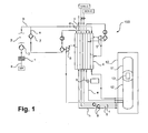
- FIG. 1 an air separation plant according to a particularly preferred embodiment of the invention is shown schematically and designated 100 in total.
- the air separation plant 100 is supplied to feed air (AIR) in the form of an input air flow a, pre-cleaned by a filter 1 and then fed to a main air compressor 2.
- AIR feed air
- the main air compressor 2 is illustrated very schematically.
- the main air compressor 2 typically has a plurality of compressor stages, which can be driven via a common shaft with one or more electric motors.
- this compressed feed air flow a Downstream of the main air compressor 2 is compressed in this compressed feed air flow a, which is here the entire, in the air separation plant treated feed air 100, a cleaning device 3, not shown, and there free of residual moisture and carbon dioxide, for example.
- It will be a compressed (and purified) feed air stream b obtained downstream of the cleaning device 3 at a pressure level of, for example, 15 to 23 bar, referred to in this application as the third pressure level, is present.
- the third pressure level in the illustrated example is well above the operating pressure of a typical high-pressure column of an air separation plant, as explained above. This is a HAP procedure.
- the feed air stream b is successively divided into the streams c, d and e.
- the current c is referred to as the first portion
- the current d as the second portion
- the current e as the third portion of the feed air flow b.
- the streams c and d are separated from each other warmly supplied to a main heat exchanger 4 of the air separation plant 100 and this removed again at different intermediate temperature levels.
- the stream c is after removal from the main heat exchanger 4 in an expansion turbine 5, which is referred to in the context of this application as the first expansion turbine to a pressure level of for example 5 to 6 bar, which is referred to in the context of this application as a second pressure level, relaxed, and again passed through a section of the main heat exchanger 4.
- the stream d is also released to the second pressure level after removal from the main heat exchanger 4 in an expansion turbine 6, which is referred to in the context of this application as a second expansion turbine.
- the current e is the so-called inductor current, which in particular enables internal compression.
- the current e is for this purpose first in a booster 7 and then in two turbine booster, which are each driven by the first expansion turbine 5 and the second expansion turbine 6 (not separately designated), re-compressed.
- the turbine booster driven by the second expansion turbine 6 is referred to here as the first turbine booster, whereas the turbine booster driven by the first expansion turbine 5 is referred to as the second turbine booster.
- the recompression takes place at a pressure level of for example 50 to 70 bar, which is referred to in the context of this application as the fourth pressure level.
- Downstream of the booster 7 and upstream of the turbine booster is the power e at a pressure level of for example 26 to 36 bar.
- the secondary compressor 7 is driven by external energy, ie not by a relaxation of compressed air portions of the feed air stream b.
- the current e is recooled in each case in non-separately designated aftercoolers of the turbine boosters to a temperature which corresponds approximately to the cooling water temperature. A further cooling takes place as shown by means of the main heat exchanger 4 as needed.
- the current e is thus again passed through an aftercooler and then through the main heat exchanger 4 and then expanded in a sealing fluid expander 8.
- the fourth pressure level is well above the critical pressure for nitrogen and above the critical pressure for oxygen.
- the flow e After cooling in the main heat exchanger 4 and upstream of the sealing fluid expander 8, the flow e is in the liquid state at supercritical pressure.
- the sealing fluid expander 8 is coupled, for example, with a generator or an oil brake (without designation). After relaxation, the current e is here at the second pressure level. He is still liquid, but is at a subcritical pressure.
- the distillation column system 10 is shown greatly simplified. It comprises at least one at a pressure level of 1 to 2 bar (referred to here as the first pressure level) operated low pressure column 11 and operated at the second pressure level high pressure column 12 of a double column system in which the low pressure column 11 and the high pressure column 12 via a main condenser 13 in heat exchanging connection stand.
- the first pressure level a pressure level of 1 to 2 bar
- the second pressure level high pressure column 12 of a double column system in which the low pressure column 11 and the high pressure column 12 via a main condenser 13 in heat exchanging connection stand.
- valves, pumps, other heat exchangers and the like has been omitted for clarity.
- the streams c, d and e are fed into the high pressure column 12 in the example shown. However, it can also be provided, for example, not to feed the stream d and / or the stream e into the distillation column system after appropriate expansion into the low-pressure column 11 and / or portions.
- the distillation column system 10, the currents f, g and h can be removed in the example shown.
- the air separation plant 100 is set up to carry out an internal compression process, as explained in more detail.
- the streams f and g which may be a liquid, oxygen-rich stream f and a liquid, nitrogen-rich stream g, are therefore pressurized by means of pumps 9 in the liquid state and vaporized in the main heat exchanger 4 or, depending on the pressure , transferred from the liquid to the supercritical state.
- Fluid of the flows f and g can be taken from the air separation plant 100 as internally compressed oxygen (GOX-IC) or internally compressed nitrogen (GAN-IC).
- Stream h illustrates one or more streams taken from the distillation column system 10 in the gaseous state at the first pressure level.
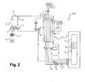
- FIG. 2 an air separation plant according to a particularly preferred embodiment of the invention is shown schematically and indicated generally at 200. Equal or comparable plant components and currents as in FIG. 1 shown air separation unit 100 are given identical reference numerals and will not be explained repeatedly.
- the feed air stream b is also present downstream of the cleaning device 3 at a third pressure level, which, however, here is for example 9 to 17 bar.
- the fourth pressure level, to which the current e (inductor current) is compressed, is for example 30 to 80 bar here. While the stream e here after the Nachverdichtungsuze in the first turbine booster in a not separately designated aftercooler is cooled back to a temperature which corresponds approximately to the cooling water temperature, cooling takes place downstream of the second turbine booster only by means of the main heat exchanger 4, but not by means of an aftercooler such in the air separation plant 100 according to FIG. 1 , Since the second turbine booster is operated as a "cold" turbine booster, the current e downstream of this second turbine booster is at a correspondingly low temperature level well below the ambient temperature.
- the air separation plant 100, the drive of the booster 7 is carried out together with one or more compressor stages of the Main air compressor 2 and using a pressurized fluid, such as pressure steam, which is in an expansion turbine (not separately referred to) relaxed.
- a pressurized fluid such as pressure steam
- an air separation plant 100 is suitable according to FIG. 1 in which the second turbine booster is operated as a "warm” turbine booster, especially for the provision of larger quantities of liquid air products (not shown), an air separation plant 200 according to FIG FIG. 2 whereas the second turbine booster operates as a "cold” turbine booster, especially for providing high pressure gaseous internal compression products.
Priority Applications (6)
| Application Number | Priority Date | Filing Date | Title |
|---|---|---|---|
| EP14002683.2A EP2980514A1 (fr) | 2014-07-31 | 2014-07-31 | Procédé de séparation cryogénique de l'air et installation de séparation d'air |
| EP15742185.0A EP3175192A1 (fr) | 2014-07-31 | 2015-07-28 | Procédé de séparation cryogénique de l'air et installation de séparation d'air |
| CN201580049883.8A CN106716033B (zh) | 2014-07-31 | 2015-07-28 | 空气的低温分离方法和空气分离设备 |
| PCT/EP2015/001554 WO2016015860A1 (fr) | 2014-07-31 | 2015-07-28 | Procédé de séparation cryogénique de l'air et installation de séparation d'air |
| US15/328,995 US10480853B2 (en) | 2014-07-31 | 2015-07-28 | Method for the cryogenic separation of air and air separation plant |
| SA517380791A SA517380791B1 (ar) | 2014-07-31 | 2017-01-25 | طريقة لفصل الهواء بالتبريد ومحطة فصل هواء |
Applications Claiming Priority (1)
| Application Number | Priority Date | Filing Date | Title |
|---|---|---|---|
| EP14002683.2A EP2980514A1 (fr) | 2014-07-31 | 2014-07-31 | Procédé de séparation cryogénique de l'air et installation de séparation d'air |
Publications (1)
| Publication Number | Publication Date |
|---|---|
| EP2980514A1 true EP2980514A1 (fr) | 2016-02-03 |
Family
ID=51266069
Family Applications (2)
| Application Number | Title | Priority Date | Filing Date |
|---|---|---|---|
| EP14002683.2A Withdrawn EP2980514A1 (fr) | 2014-07-31 | 2014-07-31 | Procédé de séparation cryogénique de l'air et installation de séparation d'air |
| EP15742185.0A Pending EP3175192A1 (fr) | 2014-07-31 | 2015-07-28 | Procédé de séparation cryogénique de l'air et installation de séparation d'air |
Family Applications After (1)
| Application Number | Title | Priority Date | Filing Date |
|---|---|---|---|
| EP15742185.0A Pending EP3175192A1 (fr) | 2014-07-31 | 2015-07-28 | Procédé de séparation cryogénique de l'air et installation de séparation d'air |
Country Status (5)
| Country | Link |
|---|---|
| US (1) | US10480853B2 (fr) |
| EP (2) | EP2980514A1 (fr) |
| CN (1) | CN106716033B (fr) |
| SA (1) | SA517380791B1 (fr) |
| WO (1) | WO2016015860A1 (fr) |
Cited By (25)
| Publication number | Priority date | Publication date | Assignee | Title |
|---|---|---|---|---|
| EP3179187A1 (fr) * | 2015-12-07 | 2017-06-14 | Linde Aktiengesellschaft | Procédé de production d'un produit comprime riche en oxygène, gazeux et liquide dans une installation de décomposition de l'air et installation de décomposition de l'air |
| EP3312533A1 (fr) | 2016-10-18 | 2018-04-25 | Linde Aktiengesellschaft | Procédé de séparation de l'air et installation de séparation de l'air |
| DE102017010001A1 (de) | 2016-11-04 | 2018-05-09 | Linde Aktiengesellschaft | Verfahren und Anlage zur Tieftemperaturzerlegung von Luft |
| DE102016015292A1 (de) | 2016-12-22 | 2018-06-28 | Linde Aktiengesellschaft | Verfahren zur Bereitstellung eines oder mehrerer Luftprodukte mit einer Luftzerlegungsanlage |
| EP3343158A1 (fr) | 2016-12-28 | 2018-07-04 | Linde Aktiengesellschaft | Procédé de production d'un ou plusieurs produits pneumatiques et unité de fractionnement d'air |
| EP3410050A1 (fr) | 2017-06-02 | 2018-12-05 | Linde Aktiengesellschaft | Procédé de production d'un ou de plusieurs produits pneumatiques et installation de séparation d'air |
| WO2018219501A1 (fr) | 2017-05-31 | 2018-12-06 | Linde Aktiengesellschaft | Procédé pour produire un ou plusieurs produits formés à partir d'air et installation de séparation d'air |
| DE202018005045U1 (de) | 2018-10-31 | 2018-12-17 | Linde Aktiengesellschaft | Anlage zur Gewinnung von Argon durch Tieftemperaturzerlegung von Luft |
| WO2019214847A1 (fr) | 2018-05-07 | 2019-11-14 | Linde Aktiengesellschaft | Procédé pour produire un ou plusieurs produit(s) formés à partir d'air et installation de séparation d'air |
| EP3620739A1 (fr) | 2018-09-05 | 2020-03-11 | Linde Aktiengesellschaft | Procédé de décomposition à basse température de l'air et installation de décomposition de l'air |
| WO2020074120A1 (fr) | 2018-10-09 | 2020-04-16 | Linde Aktiengesellschaft | Procédé pour produire un ou plusieurs produits formés à partir d'air et installation de séparation d'air |
| WO2020083520A1 (fr) | 2018-10-26 | 2020-04-30 | Linde Aktiengesellschaft | Procédé pour extraire un ou plusieurs produits de l'air et installation de séparation d'air |
| EP3671085A1 (fr) | 2018-12-18 | 2020-06-24 | Linde GmbH | Dispositif et procédé de récupération de la chaleur de compression à partir de l'air comprimé et traité dans une installation de traitement de l'air |
| DE102019000335A1 (de) | 2019-01-18 | 2020-07-23 | Linde Aktiengesellschaft | Verfahren zur Bereitstellung von Luftprodukten und Luftzerlegungsanlage |
| EP3696486A1 (fr) | 2019-02-13 | 2020-08-19 | Linde GmbH | Procédé et installation de fourniture d'un ou d'une pluralité de produits dérivés de l'air gazeux, riches en oxygène |
| EP3699535A1 (fr) | 2019-02-19 | 2020-08-26 | Linde GmbH | Procédé et installation de séparation d'air permettant de fournir de manière variable un produit dérivé de l'air gazeux sous pression |
| EP3699534A1 (fr) | 2019-02-19 | 2020-08-26 | Linde GmbH | Procédé et installation de séparation d'air permettant de fournir de manière variable un produit dérivé de l'air gazeux sous pression |
| DE202021002439U1 (de) | 2021-07-17 | 2021-10-20 | Linde Gmbh | Verdichter |
| DE202021002895U1 (de) | 2021-09-07 | 2022-02-09 | Linde GmbH | Anlage zur Tieftemperaturzerlegung von Luft |
| WO2022053173A1 (fr) | 2020-09-08 | 2022-03-17 | Linde Gmbh | Procédé et installation de fractionnement d'air cryogénique |
| WO2022053172A1 (fr) | 2020-09-08 | 2022-03-17 | Linde Gmbh | Procédé d'obtention d'un ou de plusieurs produits à base d'air, et installation de fractionnement d'air |
| WO2022111850A1 (fr) | 2020-11-24 | 2022-06-02 | Linde Gmbh | Procédé et installation de séparation cryogénique d'air |
| WO2022263013A1 (fr) | 2021-06-17 | 2022-12-22 | Linde Gmbh | Procédé et installation permettant de fournir un produit à base d'air gazeux sous pression riche en oxygène |
| WO2023030689A1 (fr) | 2021-09-02 | 2023-03-09 | Linde Gmbh | Procédé pour obtenir un ou plusieurs produits de l'air et installation de séparation d'air |
| WO2023051946A1 (fr) | 2021-09-29 | 2023-04-06 | Linde Gmbh | Procédé de séparation cryogénique de l'air et installation de séparation d'air |
Families Citing this family (5)
| Publication number | Priority date | Publication date | Assignee | Title |
|---|---|---|---|---|
| WO2020244801A1 (fr) * | 2019-06-04 | 2020-12-10 | Linde Gmbh | Procédé et installation de décomposition d'air à basse température |
| CN112361716A (zh) * | 2020-10-26 | 2021-02-12 | 乔治洛德方法研究和开发液化空气有限公司 | 用于从空气分离装置中制备高压气体的方法和装置 |
| WO2022093043A1 (fr) * | 2020-10-27 | 2022-05-05 | Fabrum Holdings Limited | Système de traitement d'air et procédé de traitement d'air |
| CN113758150A (zh) * | 2021-09-18 | 2021-12-07 | 乔治洛德方法研究和开发液化空气有限公司 | 空气的低温分离方法和空气分离装置 |
| EP4151940A1 (fr) | 2021-09-18 | 2023-03-22 | L'air Liquide, Societe Anonyme Pour L'etude Et L'exploitation Des Procedes Georges Claude | Procédé et appareil de séparation cryogénique d'air |
Citations (10)
| Publication number | Priority date | Publication date | Assignee | Title |
|---|---|---|---|---|
| US5329776A (en) | 1991-03-11 | 1994-07-19 | L'air Liquide, Societe Anonyme Pour L'etude Et L'exploitation Des Procedes Georges Claude | Process and apparatus for the production of gaseous oxygen under pressure |
| US5564290A (en) * | 1995-09-29 | 1996-10-15 | Praxair Technology, Inc. | Cryogenic rectification system with dual phase turboexpansion |
| US20050126221A1 (en) * | 2003-12-10 | 2005-06-16 | Bao Ha | Process and apparatus for the separation of air by cryogenic distillation |
| DE102007014643A1 (de) * | 2007-03-27 | 2007-09-20 | Linde Ag | Verfahren und Vorrichtung zur Erzeugung von gasförmigem Druckprodukt durch Tieftemperaturzerlegung von Luft |
| DE102006012241A1 (de) * | 2006-03-15 | 2007-09-20 | Linde Ag | Verfahren und Vorrichtung zur Tieftemperaturzerlegung von Luft |
| EP2458311A1 (fr) | 2010-11-25 | 2012-05-30 | Linde Aktiengesellschaft | Procédé et dispositif de production d'un produit d'impression gazeux par décomposition à basse température d'air |
| EP2466236A1 (fr) | 2010-11-25 | 2012-06-20 | Linde Aktiengesellschaft | Procédé de production d'un produit d'impression gazeux par décomposition à basse température de l'air |
| EP2520886A1 (fr) * | 2011-05-05 | 2012-11-07 | Linde AG | Procédé et dispositif de production d'un produit comprimé à oxygène gazeux par décomposition à basse température d'air |
| EP2634517A1 (fr) * | 2012-02-29 | 2013-09-04 | L'Air Liquide Société Anonyme pour l'Etude et l'Exploitation des Procédés Georges Claude | Procédé et appareil pour la séparation d'air par distillation cryogénique |
| US20130255313A1 (en) * | 2012-03-29 | 2013-10-03 | Bao Ha | Process for the separation of air by cryogenic distillation |
Family Cites Families (19)
| Publication number | Priority date | Publication date | Assignee | Title |
|---|---|---|---|---|
| US20030000248A1 (en) * | 2001-06-18 | 2003-01-02 | Brostow Adam Adrian | Medium-pressure nitrogen production with high oxygen recovery |
| US7272954B2 (en) * | 2004-07-14 | 2007-09-25 | L'air Liquide, Societe Anonyme A Directoire Et Conseil De Surveillance Pour L'etude Et L'exploitation Des Proceded Georges Claude | Low temperature air separation process for producing pressurized gaseous product |
| EP1767884A1 (fr) * | 2005-09-23 | 2007-03-28 | L'Air Liquide Société Anon. à Directoire et Conseil de Surveillance pour l'Etude et l'Exploitation des Procédés Georges Claude | Procédé et dispositif pour la séparation cryogénique d'air |
| US7533540B2 (en) * | 2006-03-10 | 2009-05-19 | Praxair Technology, Inc. | Cryogenic air separation system for enhanced liquid production |
| US8136369B2 (en) * | 2006-07-14 | 2012-03-20 | L'air Liquide Societe Anonyme Pour L'etude | System and apparatus for providing low pressure and low purity oxygen |
| US20080223077A1 (en) * | 2007-03-13 | 2008-09-18 | Neil Mark Prosser | Air separation method |
| DE102007031765A1 (de) * | 2007-07-07 | 2009-01-08 | Linde Ag | Verfahren zur Tieftemperaturzerlegung von Luft |
| DE102007031759A1 (de) * | 2007-07-07 | 2009-01-08 | Linde Ag | Verfahren und Vorrichtung zur Erzeugung von gasförmigem Druckprodukt durch Tieftemperaturzerlegung von Luft |
| US20090320520A1 (en) * | 2008-06-30 | 2009-12-31 | David Ross Parsnick | Nitrogen liquefier retrofit for an air separation plant |
| US8443625B2 (en) * | 2008-08-14 | 2013-05-21 | Praxair Technology, Inc. | Krypton and xenon recovery method |
| US8397535B2 (en) * | 2009-06-16 | 2013-03-19 | Praxair Technology, Inc. | Method and apparatus for pressurized product production |
| US9182170B2 (en) * | 2009-10-13 | 2015-11-10 | Praxair Technology, Inc. | Oxygen vaporization method and system |
| US9518778B2 (en) * | 2012-12-26 | 2016-12-13 | Praxair Technology, Inc. | Air separation method and apparatus |
| EP2938952A2 (fr) * | 2012-12-27 | 2015-11-04 | Linde Aktiengesellschaft | Procédé et dispositif de séparation de l'air à basse température |
| EP2770286B1 (fr) * | 2013-02-21 | 2017-05-24 | Linde Aktiengesellschaft | Procédé et dispositif de collecte d'oxygène et d'azote sous haute pression |
| WO2014146779A2 (fr) * | 2013-03-19 | 2014-09-25 | Linde Aktiengesellschaft | Procédé et dispositif de production d'azote gazeux sous pression |
| FR3010778B1 (fr) * | 2013-09-17 | 2019-05-24 | Air Liquide | Procede et appareil de production d'oxygene gazeux par distillation cryogenique de l'air |
| US20160025408A1 (en) * | 2014-07-28 | 2016-01-28 | Zhengrong Xu | Air separation method and apparatus |
| US20160245585A1 (en) * | 2015-02-24 | 2016-08-25 | Henry E. Howard | System and method for integrated air separation and liquefaction |
-
2014
- 2014-07-31 EP EP14002683.2A patent/EP2980514A1/fr not_active Withdrawn
-
2015
- 2015-07-28 EP EP15742185.0A patent/EP3175192A1/fr active Pending
- 2015-07-28 WO PCT/EP2015/001554 patent/WO2016015860A1/fr active Application Filing
- 2015-07-28 US US15/328,995 patent/US10480853B2/en active Active
- 2015-07-28 CN CN201580049883.8A patent/CN106716033B/zh active Active
-
2017
- 2017-01-25 SA SA517380791A patent/SA517380791B1/ar unknown
Patent Citations (10)
| Publication number | Priority date | Publication date | Assignee | Title |
|---|---|---|---|---|
| US5329776A (en) | 1991-03-11 | 1994-07-19 | L'air Liquide, Societe Anonyme Pour L'etude Et L'exploitation Des Procedes Georges Claude | Process and apparatus for the production of gaseous oxygen under pressure |
| US5564290A (en) * | 1995-09-29 | 1996-10-15 | Praxair Technology, Inc. | Cryogenic rectification system with dual phase turboexpansion |
| US20050126221A1 (en) * | 2003-12-10 | 2005-06-16 | Bao Ha | Process and apparatus for the separation of air by cryogenic distillation |
| DE102006012241A1 (de) * | 2006-03-15 | 2007-09-20 | Linde Ag | Verfahren und Vorrichtung zur Tieftemperaturzerlegung von Luft |
| DE102007014643A1 (de) * | 2007-03-27 | 2007-09-20 | Linde Ag | Verfahren und Vorrichtung zur Erzeugung von gasförmigem Druckprodukt durch Tieftemperaturzerlegung von Luft |
| EP2458311A1 (fr) | 2010-11-25 | 2012-05-30 | Linde Aktiengesellschaft | Procédé et dispositif de production d'un produit d'impression gazeux par décomposition à basse température d'air |
| EP2466236A1 (fr) | 2010-11-25 | 2012-06-20 | Linde Aktiengesellschaft | Procédé de production d'un produit d'impression gazeux par décomposition à basse température de l'air |
| EP2520886A1 (fr) * | 2011-05-05 | 2012-11-07 | Linde AG | Procédé et dispositif de production d'un produit comprimé à oxygène gazeux par décomposition à basse température d'air |
| EP2634517A1 (fr) * | 2012-02-29 | 2013-09-04 | L'Air Liquide Société Anonyme pour l'Etude et l'Exploitation des Procédés Georges Claude | Procédé et appareil pour la séparation d'air par distillation cryogénique |
| US20130255313A1 (en) * | 2012-03-29 | 2013-10-03 | Bao Ha | Process for the separation of air by cryogenic distillation |
Non-Patent Citations (1)
| Title |
|---|
| "Industrial Gases Processing", 2006, WILEY-VCH |
Cited By (29)
| Publication number | Priority date | Publication date | Assignee | Title |
|---|---|---|---|---|
| EP3179187A1 (fr) * | 2015-12-07 | 2017-06-14 | Linde Aktiengesellschaft | Procédé de production d'un produit comprime riche en oxygène, gazeux et liquide dans une installation de décomposition de l'air et installation de décomposition de l'air |
| EP3312533A1 (fr) | 2016-10-18 | 2018-04-25 | Linde Aktiengesellschaft | Procédé de séparation de l'air et installation de séparation de l'air |
| DE102017010001A1 (de) | 2016-11-04 | 2018-05-09 | Linde Aktiengesellschaft | Verfahren und Anlage zur Tieftemperaturzerlegung von Luft |
| DE102016015292A1 (de) | 2016-12-22 | 2018-06-28 | Linde Aktiengesellschaft | Verfahren zur Bereitstellung eines oder mehrerer Luftprodukte mit einer Luftzerlegungsanlage |
| EP3343158A1 (fr) | 2016-12-28 | 2018-07-04 | Linde Aktiengesellschaft | Procédé de production d'un ou plusieurs produits pneumatiques et unité de fractionnement d'air |
| WO2018219501A1 (fr) | 2017-05-31 | 2018-12-06 | Linde Aktiengesellschaft | Procédé pour produire un ou plusieurs produits formés à partir d'air et installation de séparation d'air |
| RU2768445C2 (ru) * | 2017-06-02 | 2022-03-24 | Линде Акциенгезельшафт | Способ получения одного или более продуктов из воздуха и установка по разделению воздуха |
| EP3410050A1 (fr) | 2017-06-02 | 2018-12-05 | Linde Aktiengesellschaft | Procédé de production d'un ou de plusieurs produits pneumatiques et installation de séparation d'air |
| WO2019214847A1 (fr) | 2018-05-07 | 2019-11-14 | Linde Aktiengesellschaft | Procédé pour produire un ou plusieurs produit(s) formés à partir d'air et installation de séparation d'air |
| EP3620739A1 (fr) | 2018-09-05 | 2020-03-11 | Linde Aktiengesellschaft | Procédé de décomposition à basse température de l'air et installation de décomposition de l'air |
| WO2020048634A1 (fr) | 2018-09-05 | 2020-03-12 | Linde Aktiengesellschaft | Procédé de séparation cryogénique d'air et système de séparation d'air |
| WO2020074120A1 (fr) | 2018-10-09 | 2020-04-16 | Linde Aktiengesellschaft | Procédé pour produire un ou plusieurs produits formés à partir d'air et installation de séparation d'air |
| WO2020083520A1 (fr) | 2018-10-26 | 2020-04-30 | Linde Aktiengesellschaft | Procédé pour extraire un ou plusieurs produits de l'air et installation de séparation d'air |
| DE202018005045U1 (de) | 2018-10-31 | 2018-12-17 | Linde Aktiengesellschaft | Anlage zur Gewinnung von Argon durch Tieftemperaturzerlegung von Luft |
| EP3647701A1 (fr) | 2018-10-31 | 2020-05-06 | Linde Aktiengesellschaft | Installation de production d'argon par séparation d'air à basse température |
| EP3671085A1 (fr) | 2018-12-18 | 2020-06-24 | Linde GmbH | Dispositif et procédé de récupération de la chaleur de compression à partir de l'air comprimé et traité dans une installation de traitement de l'air |
| DE102019000335A1 (de) | 2019-01-18 | 2020-07-23 | Linde Aktiengesellschaft | Verfahren zur Bereitstellung von Luftprodukten und Luftzerlegungsanlage |
| EP3696486A1 (fr) | 2019-02-13 | 2020-08-19 | Linde GmbH | Procédé et installation de fourniture d'un ou d'une pluralité de produits dérivés de l'air gazeux, riches en oxygène |
| WO2020164799A1 (fr) | 2019-02-13 | 2020-08-20 | Linde Gmbh | Procédé et installation pour fournir un ou plusieurs produits présents dans l'air, gazeux et à teneur élevée en oxygène |
| EP3699535A1 (fr) | 2019-02-19 | 2020-08-26 | Linde GmbH | Procédé et installation de séparation d'air permettant de fournir de manière variable un produit dérivé de l'air gazeux sous pression |
| EP3699534A1 (fr) | 2019-02-19 | 2020-08-26 | Linde GmbH | Procédé et installation de séparation d'air permettant de fournir de manière variable un produit dérivé de l'air gazeux sous pression |
| WO2022053173A1 (fr) | 2020-09-08 | 2022-03-17 | Linde Gmbh | Procédé et installation de fractionnement d'air cryogénique |
| WO2022053172A1 (fr) | 2020-09-08 | 2022-03-17 | Linde Gmbh | Procédé d'obtention d'un ou de plusieurs produits à base d'air, et installation de fractionnement d'air |
| WO2022111850A1 (fr) | 2020-11-24 | 2022-06-02 | Linde Gmbh | Procédé et installation de séparation cryogénique d'air |
| WO2022263013A1 (fr) | 2021-06-17 | 2022-12-22 | Linde Gmbh | Procédé et installation permettant de fournir un produit à base d'air gazeux sous pression riche en oxygène |
| DE202021002439U1 (de) | 2021-07-17 | 2021-10-20 | Linde Gmbh | Verdichter |
| WO2023030689A1 (fr) | 2021-09-02 | 2023-03-09 | Linde Gmbh | Procédé pour obtenir un ou plusieurs produits de l'air et installation de séparation d'air |
| DE202021002895U1 (de) | 2021-09-07 | 2022-02-09 | Linde GmbH | Anlage zur Tieftemperaturzerlegung von Luft |
| WO2023051946A1 (fr) | 2021-09-29 | 2023-04-06 | Linde Gmbh | Procédé de séparation cryogénique de l'air et installation de séparation d'air |
Also Published As
| Publication number | Publication date |
|---|---|
| US10480853B2 (en) | 2019-11-19 |
| EP3175192A1 (fr) | 2017-06-07 |
| WO2016015860A1 (fr) | 2016-02-04 |
| CN106716033A (zh) | 2017-05-24 |
| US20170234614A1 (en) | 2017-08-17 |
| CN106716033B (zh) | 2020-03-31 |
| SA517380791B1 (ar) | 2020-12-16 |
Similar Documents
| Publication | Publication Date | Title |
|---|---|---|
| EP2980514A1 (fr) | Procédé de séparation cryogénique de l'air et installation de séparation d'air | |
| WO2007104449A1 (fr) | Procédé et dispositif de décomposition de l'air à basse température | |
| EP3179187B1 (fr) | Procédé de production d'un produit comprime riche en oxygène, gazeux et liquide dans une installation de décomposition de l'air et installation de décomposition de l'air | |
| DE102010052545A1 (de) | Verfahren und Vorrichtung zur Gewinnung eines gasförmigen Druckprodukts durch Tieftemperaturzerlegung von Luft | |
| EP2789958A1 (fr) | Procédé de décomposition à basse température de l'air et installation de décomposition de l'air | |
| EP1067345A1 (fr) | Procédé et dispositif pour la séparation cryogénique des constituants de l'air | |
| EP3101374A2 (fr) | Procede et installation cryogeniques de separation d'air | |
| EP3343158A1 (fr) | Procédé de production d'un ou plusieurs produits pneumatiques et unité de fractionnement d'air | |
| EP3410050A1 (fr) | Procédé de production d'un ou de plusieurs produits pneumatiques et installation de séparation d'air | |
| EP2835507B1 (fr) | Procédé pour la production d'énergie électrique et installation de production d'énergie | |
| EP3196573A1 (fr) | Procede de production d'un produit pneumatique et installation de decomposition d'air | |
| WO2021104668A1 (fr) | Procédé et installation pour fractionnement à basse température de l'air | |
| EP3019804A2 (fr) | Procédé de production d'au moins un produit dérivé de l'air, installation de décomposition d'air, procédé et dispositif de production d'énergie électrique | |
| WO2020164799A1 (fr) | Procédé et installation pour fournir un ou plusieurs produits présents dans l'air, gazeux et à teneur élevée en oxygène | |
| WO2014154339A2 (fr) | Procédé de séparation d'air et installation de séparation d'air | |
| EP3034974A1 (fr) | Procédé et installation de liquéfaction d'air et de stockage et de récupération d'énergie électrique | |
| EP1199532B1 (fr) | Système de séparation d'air cryogénique à trois colonnes | |
| EP2824407A1 (fr) | Procédé de génération d'au moins un produit de l'air, installation de décomposition de l'air, procédé et dispositif de production d'énergie électrique | |
| EP2770286B1 (fr) | Procédé et dispositif de collecte d'oxygène et d'azote sous haute pression | |
| EP3312533A1 (fr) | Procédé de séparation de l'air et installation de séparation de l'air | |
| WO2021204424A2 (fr) | Procédé de séparation d'air à basse température, installation de séparation d'air et ensemble composé d'au moins deux installations de séparation d'air | |
| DE10045128A1 (de) | Verfahren und Vorrichtung zur Erzeugung hoch reinen Stickstoffs durch Tieftemperatur-Luftzerlegung | |
| EP2835506A1 (fr) | Procédé pour la production d'énergie électrique et installation de production d'énergie | |
| DE102021117030B4 (de) | Gasgemisch-Zerlegungsanlage sowie Verfahren zum Abtrennen von wenigstens einem Hauptfluid aus einem Gasgemisch | |
| DE102010056569A1 (de) | Verfahren und Vorrichtung zur Gewinnung von Druckstickstoff durch Tieftemperaturzerlegung von Luft |
Legal Events
| Date | Code | Title | Description |
|---|---|---|---|
| PUAI | Public reference made under article 153(3) epc to a published international application that has entered the european phase |
Free format text: ORIGINAL CODE: 0009012 |
|
| AK | Designated contracting states |
Kind code of ref document: A1 Designated state(s): AL AT BE BG CH CY CZ DE DK EE ES FI FR GB GR HR HU IE IS IT LI LT LU LV MC MK MT NL NO PL PT RO RS SE SI SK SM TR |
|
| AX | Request for extension of the european patent |
Extension state: BA ME |
|
| STAA | Information on the status of an ep patent application or granted ep patent |
Free format text: STATUS: THE APPLICATION IS DEEMED TO BE WITHDRAWN |
|
| 18D | Application deemed to be withdrawn |
Effective date: 20160804 |