EP3696486A1 - Procédé et installation de fourniture d'un ou d'une pluralité de produits dérivés de l'air gazeux, riches en oxygène - Google Patents
Procédé et installation de fourniture d'un ou d'une pluralité de produits dérivés de l'air gazeux, riches en oxygène Download PDFInfo
- Publication number
- EP3696486A1 EP3696486A1 EP19020068.3A EP19020068A EP3696486A1 EP 3696486 A1 EP3696486 A1 EP 3696486A1 EP 19020068 A EP19020068 A EP 19020068A EP 3696486 A1 EP3696486 A1 EP 3696486A1
- Authority
- EP
- European Patent Office
- Prior art keywords
- air
- process stream
- level
- pressure
- pressure level
- Prior art date
- Legal status (The legal status is an assumption and is not a legal conclusion. Google has not performed a legal analysis and makes no representation as to the accuracy of the status listed.)
- Withdrawn
Links
Images


Classifications
-
- F—MECHANICAL ENGINEERING; LIGHTING; HEATING; WEAPONS; BLASTING
- F25—REFRIGERATION OR COOLING; COMBINED HEATING AND REFRIGERATION SYSTEMS; HEAT PUMP SYSTEMS; MANUFACTURE OR STORAGE OF ICE; LIQUEFACTION SOLIDIFICATION OF GASES
- F25J—LIQUEFACTION, SOLIDIFICATION OR SEPARATION OF GASES OR GASEOUS OR LIQUEFIED GASEOUS MIXTURES BY PRESSURE AND COLD TREATMENT OR BY BRINGING THEM INTO THE SUPERCRITICAL STATE
- F25J3/00—Processes or apparatus for separating the constituents of gaseous or liquefied gaseous mixtures involving the use of liquefaction or solidification
- F25J3/02—Processes or apparatus for separating the constituents of gaseous or liquefied gaseous mixtures involving the use of liquefaction or solidification by rectification, i.e. by continuous interchange of heat and material between a vapour stream and a liquid stream
- F25J3/04—Processes or apparatus for separating the constituents of gaseous or liquefied gaseous mixtures involving the use of liquefaction or solidification by rectification, i.e. by continuous interchange of heat and material between a vapour stream and a liquid stream for air
- F25J3/04006—Providing pressurised feed air or process streams within or from the air fractionation unit
- F25J3/04012—Providing pressurised feed air or process streams within or from the air fractionation unit by compression of warm gaseous streams; details of intake or interstage cooling
- F25J3/04018—Providing pressurised feed air or process streams within or from the air fractionation unit by compression of warm gaseous streams; details of intake or interstage cooling of main feed air
-
- F—MECHANICAL ENGINEERING; LIGHTING; HEATING; WEAPONS; BLASTING
- F25—REFRIGERATION OR COOLING; COMBINED HEATING AND REFRIGERATION SYSTEMS; HEAT PUMP SYSTEMS; MANUFACTURE OR STORAGE OF ICE; LIQUEFACTION SOLIDIFICATION OF GASES
- F25J—LIQUEFACTION, SOLIDIFICATION OR SEPARATION OF GASES OR GASEOUS OR LIQUEFIED GASEOUS MIXTURES BY PRESSURE AND COLD TREATMENT OR BY BRINGING THEM INTO THE SUPERCRITICAL STATE
- F25J3/00—Processes or apparatus for separating the constituents of gaseous or liquefied gaseous mixtures involving the use of liquefaction or solidification
- F25J3/02—Processes or apparatus for separating the constituents of gaseous or liquefied gaseous mixtures involving the use of liquefaction or solidification by rectification, i.e. by continuous interchange of heat and material between a vapour stream and a liquid stream
- F25J3/04—Processes or apparatus for separating the constituents of gaseous or liquefied gaseous mixtures involving the use of liquefaction or solidification by rectification, i.e. by continuous interchange of heat and material between a vapour stream and a liquid stream for air
- F25J3/04006—Providing pressurised feed air or process streams within or from the air fractionation unit
- F25J3/04048—Providing pressurised feed air or process streams within or from the air fractionation unit by compression of cold gaseous streams, e.g. intermediate or oxygen enriched (waste) streams
- F25J3/04054—Providing pressurised feed air or process streams within or from the air fractionation unit by compression of cold gaseous streams, e.g. intermediate or oxygen enriched (waste) streams of air
-
- F—MECHANICAL ENGINEERING; LIGHTING; HEATING; WEAPONS; BLASTING
- F25—REFRIGERATION OR COOLING; COMBINED HEATING AND REFRIGERATION SYSTEMS; HEAT PUMP SYSTEMS; MANUFACTURE OR STORAGE OF ICE; LIQUEFACTION SOLIDIFICATION OF GASES
- F25J—LIQUEFACTION, SOLIDIFICATION OR SEPARATION OF GASES OR GASEOUS OR LIQUEFIED GASEOUS MIXTURES BY PRESSURE AND COLD TREATMENT OR BY BRINGING THEM INTO THE SUPERCRITICAL STATE
- F25J3/00—Processes or apparatus for separating the constituents of gaseous or liquefied gaseous mixtures involving the use of liquefaction or solidification
- F25J3/02—Processes or apparatus for separating the constituents of gaseous or liquefied gaseous mixtures involving the use of liquefaction or solidification by rectification, i.e. by continuous interchange of heat and material between a vapour stream and a liquid stream
- F25J3/04—Processes or apparatus for separating the constituents of gaseous or liquefied gaseous mixtures involving the use of liquefaction or solidification by rectification, i.e. by continuous interchange of heat and material between a vapour stream and a liquid stream for air
- F25J3/04006—Providing pressurised feed air or process streams within or from the air fractionation unit
- F25J3/04078—Providing pressurised feed air or process streams within or from the air fractionation unit providing pressurized products by liquid compression and vaporisation with cold recovery, i.e. so-called internal compression
- F25J3/0409—Providing pressurised feed air or process streams within or from the air fractionation unit providing pressurized products by liquid compression and vaporisation with cold recovery, i.e. so-called internal compression of oxygen
-
- F—MECHANICAL ENGINEERING; LIGHTING; HEATING; WEAPONS; BLASTING
- F25—REFRIGERATION OR COOLING; COMBINED HEATING AND REFRIGERATION SYSTEMS; HEAT PUMP SYSTEMS; MANUFACTURE OR STORAGE OF ICE; LIQUEFACTION SOLIDIFICATION OF GASES
- F25J—LIQUEFACTION, SOLIDIFICATION OR SEPARATION OF GASES OR GASEOUS OR LIQUEFIED GASEOUS MIXTURES BY PRESSURE AND COLD TREATMENT OR BY BRINGING THEM INTO THE SUPERCRITICAL STATE
- F25J3/00—Processes or apparatus for separating the constituents of gaseous or liquefied gaseous mixtures involving the use of liquefaction or solidification
- F25J3/02—Processes or apparatus for separating the constituents of gaseous or liquefied gaseous mixtures involving the use of liquefaction or solidification by rectification, i.e. by continuous interchange of heat and material between a vapour stream and a liquid stream
- F25J3/04—Processes or apparatus for separating the constituents of gaseous or liquefied gaseous mixtures involving the use of liquefaction or solidification by rectification, i.e. by continuous interchange of heat and material between a vapour stream and a liquid stream for air
- F25J3/04006—Providing pressurised feed air or process streams within or from the air fractionation unit
- F25J3/04078—Providing pressurised feed air or process streams within or from the air fractionation unit providing pressurized products by liquid compression and vaporisation with cold recovery, i.e. so-called internal compression
- F25J3/04096—Providing pressurised feed air or process streams within or from the air fractionation unit providing pressurized products by liquid compression and vaporisation with cold recovery, i.e. so-called internal compression of argon or argon enriched stream
-
- F—MECHANICAL ENGINEERING; LIGHTING; HEATING; WEAPONS; BLASTING
- F25—REFRIGERATION OR COOLING; COMBINED HEATING AND REFRIGERATION SYSTEMS; HEAT PUMP SYSTEMS; MANUFACTURE OR STORAGE OF ICE; LIQUEFACTION SOLIDIFICATION OF GASES
- F25J—LIQUEFACTION, SOLIDIFICATION OR SEPARATION OF GASES OR GASEOUS OR LIQUEFIED GASEOUS MIXTURES BY PRESSURE AND COLD TREATMENT OR BY BRINGING THEM INTO THE SUPERCRITICAL STATE
- F25J3/00—Processes or apparatus for separating the constituents of gaseous or liquefied gaseous mixtures involving the use of liquefaction or solidification
- F25J3/02—Processes or apparatus for separating the constituents of gaseous or liquefied gaseous mixtures involving the use of liquefaction or solidification by rectification, i.e. by continuous interchange of heat and material between a vapour stream and a liquid stream
- F25J3/04—Processes or apparatus for separating the constituents of gaseous or liquefied gaseous mixtures involving the use of liquefaction or solidification by rectification, i.e. by continuous interchange of heat and material between a vapour stream and a liquid stream for air
- F25J3/04151—Purification and (pre-)cooling of the feed air; recuperative heat-exchange with product streams
- F25J3/04163—Hot end purification of the feed air
- F25J3/04169—Hot end purification of the feed air by adsorption of the impurities
- F25J3/04175—Hot end purification of the feed air by adsorption of the impurities at a pressure of substantially more than the highest pressure column
-
- F—MECHANICAL ENGINEERING; LIGHTING; HEATING; WEAPONS; BLASTING
- F25—REFRIGERATION OR COOLING; COMBINED HEATING AND REFRIGERATION SYSTEMS; HEAT PUMP SYSTEMS; MANUFACTURE OR STORAGE OF ICE; LIQUEFACTION SOLIDIFICATION OF GASES
- F25J—LIQUEFACTION, SOLIDIFICATION OR SEPARATION OF GASES OR GASEOUS OR LIQUEFIED GASEOUS MIXTURES BY PRESSURE AND COLD TREATMENT OR BY BRINGING THEM INTO THE SUPERCRITICAL STATE
- F25J3/00—Processes or apparatus for separating the constituents of gaseous or liquefied gaseous mixtures involving the use of liquefaction or solidification
- F25J3/02—Processes or apparatus for separating the constituents of gaseous or liquefied gaseous mixtures involving the use of liquefaction or solidification by rectification, i.e. by continuous interchange of heat and material between a vapour stream and a liquid stream
- F25J3/04—Processes or apparatus for separating the constituents of gaseous or liquefied gaseous mixtures involving the use of liquefaction or solidification by rectification, i.e. by continuous interchange of heat and material between a vapour stream and a liquid stream for air
- F25J3/04248—Generation of cold for compensating heat leaks or liquid production, e.g. by Joule-Thompson expansion
- F25J3/04284—Generation of cold for compensating heat leaks or liquid production, e.g. by Joule-Thompson expansion using internal refrigeration by open-loop gas work expansion, e.g. of intermediate or oxygen enriched (waste-)streams
- F25J3/0429—Generation of cold for compensating heat leaks or liquid production, e.g. by Joule-Thompson expansion using internal refrigeration by open-loop gas work expansion, e.g. of intermediate or oxygen enriched (waste-)streams of feed air, e.g. used as waste or product air or expanded into an auxiliary column
- F25J3/04296—Claude expansion, i.e. expanded into the main or high pressure column
-
- F—MECHANICAL ENGINEERING; LIGHTING; HEATING; WEAPONS; BLASTING
- F25—REFRIGERATION OR COOLING; COMBINED HEATING AND REFRIGERATION SYSTEMS; HEAT PUMP SYSTEMS; MANUFACTURE OR STORAGE OF ICE; LIQUEFACTION SOLIDIFICATION OF GASES
- F25J—LIQUEFACTION, SOLIDIFICATION OR SEPARATION OF GASES OR GASEOUS OR LIQUEFIED GASEOUS MIXTURES BY PRESSURE AND COLD TREATMENT OR BY BRINGING THEM INTO THE SUPERCRITICAL STATE
- F25J3/00—Processes or apparatus for separating the constituents of gaseous or liquefied gaseous mixtures involving the use of liquefaction or solidification
- F25J3/02—Processes or apparatus for separating the constituents of gaseous or liquefied gaseous mixtures involving the use of liquefaction or solidification by rectification, i.e. by continuous interchange of heat and material between a vapour stream and a liquid stream
- F25J3/04—Processes or apparatus for separating the constituents of gaseous or liquefied gaseous mixtures involving the use of liquefaction or solidification by rectification, i.e. by continuous interchange of heat and material between a vapour stream and a liquid stream for air
- F25J3/04248—Generation of cold for compensating heat leaks or liquid production, e.g. by Joule-Thompson expansion
- F25J3/04284—Generation of cold for compensating heat leaks or liquid production, e.g. by Joule-Thompson expansion using internal refrigeration by open-loop gas work expansion, e.g. of intermediate or oxygen enriched (waste-)streams
- F25J3/0429—Generation of cold for compensating heat leaks or liquid production, e.g. by Joule-Thompson expansion using internal refrigeration by open-loop gas work expansion, e.g. of intermediate or oxygen enriched (waste-)streams of feed air, e.g. used as waste or product air or expanded into an auxiliary column
- F25J3/04303—Lachmann expansion, i.e. expanded into oxygen producing or low pressure column
-
- F—MECHANICAL ENGINEERING; LIGHTING; HEATING; WEAPONS; BLASTING
- F25—REFRIGERATION OR COOLING; COMBINED HEATING AND REFRIGERATION SYSTEMS; HEAT PUMP SYSTEMS; MANUFACTURE OR STORAGE OF ICE; LIQUEFACTION SOLIDIFICATION OF GASES
- F25J—LIQUEFACTION, SOLIDIFICATION OR SEPARATION OF GASES OR GASEOUS OR LIQUEFIED GASEOUS MIXTURES BY PRESSURE AND COLD TREATMENT OR BY BRINGING THEM INTO THE SUPERCRITICAL STATE
- F25J3/00—Processes or apparatus for separating the constituents of gaseous or liquefied gaseous mixtures involving the use of liquefaction or solidification
- F25J3/02—Processes or apparatus for separating the constituents of gaseous or liquefied gaseous mixtures involving the use of liquefaction or solidification by rectification, i.e. by continuous interchange of heat and material between a vapour stream and a liquid stream
- F25J3/04—Processes or apparatus for separating the constituents of gaseous or liquefied gaseous mixtures involving the use of liquefaction or solidification by rectification, i.e. by continuous interchange of heat and material between a vapour stream and a liquid stream for air
- F25J3/04248—Generation of cold for compensating heat leaks or liquid production, e.g. by Joule-Thompson expansion
- F25J3/04375—Details relating to the work expansion, e.g. process parameter etc.
- F25J3/04381—Details relating to the work expansion, e.g. process parameter etc. using work extraction by mechanical coupling of compression and expansion so-called companders
-
- F—MECHANICAL ENGINEERING; LIGHTING; HEATING; WEAPONS; BLASTING
- F25—REFRIGERATION OR COOLING; COMBINED HEATING AND REFRIGERATION SYSTEMS; HEAT PUMP SYSTEMS; MANUFACTURE OR STORAGE OF ICE; LIQUEFACTION SOLIDIFICATION OF GASES
- F25J—LIQUEFACTION, SOLIDIFICATION OR SEPARATION OF GASES OR GASEOUS OR LIQUEFIED GASEOUS MIXTURES BY PRESSURE AND COLD TREATMENT OR BY BRINGING THEM INTO THE SUPERCRITICAL STATE
- F25J3/00—Processes or apparatus for separating the constituents of gaseous or liquefied gaseous mixtures involving the use of liquefaction or solidification
- F25J3/02—Processes or apparatus for separating the constituents of gaseous or liquefied gaseous mixtures involving the use of liquefaction or solidification by rectification, i.e. by continuous interchange of heat and material between a vapour stream and a liquid stream
- F25J3/04—Processes or apparatus for separating the constituents of gaseous or liquefied gaseous mixtures involving the use of liquefaction or solidification by rectification, i.e. by continuous interchange of heat and material between a vapour stream and a liquid stream for air
- F25J3/04248—Generation of cold for compensating heat leaks or liquid production, e.g. by Joule-Thompson expansion
- F25J3/04375—Details relating to the work expansion, e.g. process parameter etc.
- F25J3/04393—Details relating to the work expansion, e.g. process parameter etc. using multiple or multistage gas work expansion
-
- F—MECHANICAL ENGINEERING; LIGHTING; HEATING; WEAPONS; BLASTING
- F25—REFRIGERATION OR COOLING; COMBINED HEATING AND REFRIGERATION SYSTEMS; HEAT PUMP SYSTEMS; MANUFACTURE OR STORAGE OF ICE; LIQUEFACTION SOLIDIFICATION OF GASES
- F25J—LIQUEFACTION, SOLIDIFICATION OR SEPARATION OF GASES OR GASEOUS OR LIQUEFIED GASEOUS MIXTURES BY PRESSURE AND COLD TREATMENT OR BY BRINGING THEM INTO THE SUPERCRITICAL STATE
- F25J3/00—Processes or apparatus for separating the constituents of gaseous or liquefied gaseous mixtures involving the use of liquefaction or solidification
- F25J3/02—Processes or apparatus for separating the constituents of gaseous or liquefied gaseous mixtures involving the use of liquefaction or solidification by rectification, i.e. by continuous interchange of heat and material between a vapour stream and a liquid stream
- F25J3/04—Processes or apparatus for separating the constituents of gaseous or liquefied gaseous mixtures involving the use of liquefaction or solidification by rectification, i.e. by continuous interchange of heat and material between a vapour stream and a liquid stream for air
- F25J3/04406—Processes or apparatus for separating the constituents of gaseous or liquefied gaseous mixtures involving the use of liquefaction or solidification by rectification, i.e. by continuous interchange of heat and material between a vapour stream and a liquid stream for air using a dual pressure main column system
- F25J3/04412—Processes or apparatus for separating the constituents of gaseous or liquefied gaseous mixtures involving the use of liquefaction or solidification by rectification, i.e. by continuous interchange of heat and material between a vapour stream and a liquid stream for air using a dual pressure main column system in a classical double column flowsheet, i.e. with thermal coupling by a main reboiler-condenser in the bottom of low pressure respectively top of high pressure column
-
- F—MECHANICAL ENGINEERING; LIGHTING; HEATING; WEAPONS; BLASTING
- F25—REFRIGERATION OR COOLING; COMBINED HEATING AND REFRIGERATION SYSTEMS; HEAT PUMP SYSTEMS; MANUFACTURE OR STORAGE OF ICE; LIQUEFACTION SOLIDIFICATION OF GASES
- F25J—LIQUEFACTION, SOLIDIFICATION OR SEPARATION OF GASES OR GASEOUS OR LIQUEFIED GASEOUS MIXTURES BY PRESSURE AND COLD TREATMENT OR BY BRINGING THEM INTO THE SUPERCRITICAL STATE
- F25J3/00—Processes or apparatus for separating the constituents of gaseous or liquefied gaseous mixtures involving the use of liquefaction or solidification
- F25J3/02—Processes or apparatus for separating the constituents of gaseous or liquefied gaseous mixtures involving the use of liquefaction or solidification by rectification, i.e. by continuous interchange of heat and material between a vapour stream and a liquid stream
- F25J3/04—Processes or apparatus for separating the constituents of gaseous or liquefied gaseous mixtures involving the use of liquefaction or solidification by rectification, i.e. by continuous interchange of heat and material between a vapour stream and a liquid stream for air
- F25J3/04642—Recovering noble gases from air
- F25J3/04648—Recovering noble gases from air argon
- F25J3/04654—Producing crude argon in a crude argon column
- F25J3/04666—Producing crude argon in a crude argon column as a parallel working rectification column of the low pressure column in a dual pressure main column system
- F25J3/04672—Producing crude argon in a crude argon column as a parallel working rectification column of the low pressure column in a dual pressure main column system having a top condenser
- F25J3/04678—Producing crude argon in a crude argon column as a parallel working rectification column of the low pressure column in a dual pressure main column system having a top condenser cooled by oxygen enriched liquid from high pressure column bottoms
-
- F—MECHANICAL ENGINEERING; LIGHTING; HEATING; WEAPONS; BLASTING
- F25—REFRIGERATION OR COOLING; COMBINED HEATING AND REFRIGERATION SYSTEMS; HEAT PUMP SYSTEMS; MANUFACTURE OR STORAGE OF ICE; LIQUEFACTION SOLIDIFICATION OF GASES
- F25J—LIQUEFACTION, SOLIDIFICATION OR SEPARATION OF GASES OR GASEOUS OR LIQUEFIED GASEOUS MIXTURES BY PRESSURE AND COLD TREATMENT OR BY BRINGING THEM INTO THE SUPERCRITICAL STATE
- F25J3/00—Processes or apparatus for separating the constituents of gaseous or liquefied gaseous mixtures involving the use of liquefaction or solidification
- F25J3/02—Processes or apparatus for separating the constituents of gaseous or liquefied gaseous mixtures involving the use of liquefaction or solidification by rectification, i.e. by continuous interchange of heat and material between a vapour stream and a liquid stream
- F25J3/04—Processes or apparatus for separating the constituents of gaseous or liquefied gaseous mixtures involving the use of liquefaction or solidification by rectification, i.e. by continuous interchange of heat and material between a vapour stream and a liquid stream for air
- F25J3/04642—Recovering noble gases from air
- F25J3/04648—Recovering noble gases from air argon
- F25J3/04721—Producing pure argon, e.g. recovered from a crude argon column
- F25J3/04727—Producing pure argon, e.g. recovered from a crude argon column using an auxiliary pure argon column for nitrogen rejection
-
- F—MECHANICAL ENGINEERING; LIGHTING; HEATING; WEAPONS; BLASTING
- F25—REFRIGERATION OR COOLING; COMBINED HEATING AND REFRIGERATION SYSTEMS; HEAT PUMP SYSTEMS; MANUFACTURE OR STORAGE OF ICE; LIQUEFACTION SOLIDIFICATION OF GASES
- F25J—LIQUEFACTION, SOLIDIFICATION OR SEPARATION OF GASES OR GASEOUS OR LIQUEFIED GASEOUS MIXTURES BY PRESSURE AND COLD TREATMENT OR BY BRINGING THEM INTO THE SUPERCRITICAL STATE
- F25J3/00—Processes or apparatus for separating the constituents of gaseous or liquefied gaseous mixtures involving the use of liquefaction or solidification
- F25J3/02—Processes or apparatus for separating the constituents of gaseous or liquefied gaseous mixtures involving the use of liquefaction or solidification by rectification, i.e. by continuous interchange of heat and material between a vapour stream and a liquid stream
- F25J3/04—Processes or apparatus for separating the constituents of gaseous or liquefied gaseous mixtures involving the use of liquefaction or solidification by rectification, i.e. by continuous interchange of heat and material between a vapour stream and a liquid stream for air
- F25J3/04763—Start-up or control of the process; Details of the apparatus used
- F25J3/04866—Construction and layout of air fractionation equipments, e.g. valves, machines
- F25J3/04951—Arrangements of multiple air fractionation units or multiple equipments fulfilling the same process step, e.g. multiple trains in a network
- F25J3/04957—Arrangements of multiple air fractionation units or multiple equipments fulfilling the same process step, e.g. multiple trains in a network and inter-connecting equipments upstream of the fractionation unit (s), i.e. at the "front-end"
-
- F—MECHANICAL ENGINEERING; LIGHTING; HEATING; WEAPONS; BLASTING
- F25—REFRIGERATION OR COOLING; COMBINED HEATING AND REFRIGERATION SYSTEMS; HEAT PUMP SYSTEMS; MANUFACTURE OR STORAGE OF ICE; LIQUEFACTION SOLIDIFICATION OF GASES
- F25J—LIQUEFACTION, SOLIDIFICATION OR SEPARATION OF GASES OR GASEOUS OR LIQUEFIED GASEOUS MIXTURES BY PRESSURE AND COLD TREATMENT OR BY BRINGING THEM INTO THE SUPERCRITICAL STATE
- F25J2205/00—Processes or apparatus using other separation and/or other processing means
- F25J2205/02—Processes or apparatus using other separation and/or other processing means using simple phase separation in a vessel or drum
- F25J2205/04—Processes or apparatus using other separation and/or other processing means using simple phase separation in a vessel or drum in the feed line, i.e. upstream of the fractionation step
-
- F—MECHANICAL ENGINEERING; LIGHTING; HEATING; WEAPONS; BLASTING
- F25—REFRIGERATION OR COOLING; COMBINED HEATING AND REFRIGERATION SYSTEMS; HEAT PUMP SYSTEMS; MANUFACTURE OR STORAGE OF ICE; LIQUEFACTION SOLIDIFICATION OF GASES
- F25J—LIQUEFACTION, SOLIDIFICATION OR SEPARATION OF GASES OR GASEOUS OR LIQUEFIED GASEOUS MIXTURES BY PRESSURE AND COLD TREATMENT OR BY BRINGING THEM INTO THE SUPERCRITICAL STATE
- F25J2215/00—Processes characterised by the type or other details of the product stream
- F25J2215/50—Oxygen or special cases, e.g. isotope-mixtures or low purity O2
- F25J2215/54—Oxygen production with multiple pressure O2
-
- F—MECHANICAL ENGINEERING; LIGHTING; HEATING; WEAPONS; BLASTING
- F25—REFRIGERATION OR COOLING; COMBINED HEATING AND REFRIGERATION SYSTEMS; HEAT PUMP SYSTEMS; MANUFACTURE OR STORAGE OF ICE; LIQUEFACTION SOLIDIFICATION OF GASES
- F25J—LIQUEFACTION, SOLIDIFICATION OR SEPARATION OF GASES OR GASEOUS OR LIQUEFIED GASEOUS MIXTURES BY PRESSURE AND COLD TREATMENT OR BY BRINGING THEM INTO THE SUPERCRITICAL STATE
- F25J2230/00—Processes or apparatus involving steps for increasing the pressure of gaseous process streams
- F25J2230/24—Multiple compressors or compressor stages in parallel
-
- F—MECHANICAL ENGINEERING; LIGHTING; HEATING; WEAPONS; BLASTING
- F25—REFRIGERATION OR COOLING; COMBINED HEATING AND REFRIGERATION SYSTEMS; HEAT PUMP SYSTEMS; MANUFACTURE OR STORAGE OF ICE; LIQUEFACTION SOLIDIFICATION OF GASES
- F25J—LIQUEFACTION, SOLIDIFICATION OR SEPARATION OF GASES OR GASEOUS OR LIQUEFIED GASEOUS MIXTURES BY PRESSURE AND COLD TREATMENT OR BY BRINGING THEM INTO THE SUPERCRITICAL STATE
- F25J2230/00—Processes or apparatus involving steps for increasing the pressure of gaseous process streams
- F25J2230/40—Processes or apparatus involving steps for increasing the pressure of gaseous process streams the fluid being air
-
- F—MECHANICAL ENGINEERING; LIGHTING; HEATING; WEAPONS; BLASTING
- F25—REFRIGERATION OR COOLING; COMBINED HEATING AND REFRIGERATION SYSTEMS; HEAT PUMP SYSTEMS; MANUFACTURE OR STORAGE OF ICE; LIQUEFACTION SOLIDIFICATION OF GASES
- F25J—LIQUEFACTION, SOLIDIFICATION OR SEPARATION OF GASES OR GASEOUS OR LIQUEFIED GASEOUS MIXTURES BY PRESSURE AND COLD TREATMENT OR BY BRINGING THEM INTO THE SUPERCRITICAL STATE
- F25J2290/00—Other details not covered by groups F25J2200/00 - F25J2280/00
- F25J2290/60—Details about pipelines, i.e. network, for feed or product distribution
Definitions
- the invention relates to a method for providing one or more oxygen-rich, gaseous air products and a corresponding system according to the preambles of the independent claims.
- air product is intended to refer to a fluid that is provided, at least in part, by the cryogenic decomposition of atmospheric air.
- An air product has one or more air gases contained in atmospheric air in a different composition than in atmospheric air.
- An air product can basically be in a gaseous, liquid or supercritical state and can be transferred from one of these states to another.
- a liquid air product can be converted into the gaseous state (“evaporated”) or converted into the supercritical state (“pseudo-evaporated”) by heating to a certain pressure, depending on whether the pressure during the heating is below or above the critical pressure .
- Air separation plants have rectification column systems which are conventionally designed as two-column systems, in particular as classic Linde double-column systems, but can also be designed as three- or multi-column systems.
- rectification columns for obtaining nitrogen and / or oxygen in liquid and / or gaseous state, i.e. the rectification columns for nitrogen-oxygen separation
- rectification columns can be provided for obtaining further air components, in particular the noble gases krypton, xenon and / or argon.
- the terms “rectification” and “distillation” and “column” and “column” or terms composed thereof are used synonymously.
- the rectification columns of the rectification column systems mentioned are operated at different pressures.
- Known double column systems have what is known as a high pressure column (also referred to as a pressure column, medium pressure column or lower column) and a so-called low pressure column (also referred to as an upper column).
- the high pressure column is typically operated at a pressure of 4 to 7 bar, in particular approx. 5.3 bar.
- the low-pressure column is operated at a pressure of typically 1 to 2 bar, in particular about 1.4 bar. In certain cases, higher pressures can also be used in both rectification columns.
- the pressures given here are absolute pressures at the top of the columns given.
- main (air) compressors / booster Main Air Compressor / Booster Air Compressor, MAC-BAC processes or so-called high air pressure (HAP) processes
- the main compressor / booster processes are the more conventional processes, while high-air pressure processes have been used more and more recently as alternatives.
- the present invention is suitable for both variants of air separation, but can be used in particular in connection with HAP processes. Due to the significantly lower costs - main and booster compressors are integrated in one machine, so to speak - and comparable efficiency, high-air pressure processes can represent an advantageous alternative to the main compressor / booster processes.
- Main compressor / booster processes are characterized in that only part of the total amount of feed air supplied to the rectification column system is compressed to a pressure which is significantly above, ie by at least 3, 4, 5, 6, 7, 8, 9 or 10 bar the pressure at which the high pressure column is operated. A further part of the feed air quantity is only compressed to this pressure or a pressure which differs therefrom by no more than 1 to 2 bar, and at this point it is fed into the high pressure column.
- a main compressor / booster method is, for example, at Häring (see above) in Figure 2 .3A shown.
- the entire amount of feed air supplied to the rectification column system is compressed to a pressure which is substantially, ie by at least 3, 4, 5, 6, 7, 8, 9 or 10 bar, and for example up to 14, 16, 18 or 20 bar, too above the pressure at which the high pressure column is operated.
- High air pressure methods are, for example, from the EP 2 980 514 A1 and the EP 2 963 367 A1 known.
- High air pressure processes are typically used with what is known as internal compression (IV, IC).
- internal compression at least one gaseous, pressurized air product, which is provided by means of the air separation plant, is formed in that a cryogenic, liquid air product is removed from the rectification column system, subjected to a pressure increase to a product pressure, and the product pressure by heating into the gaseous or supercritical state is convicted.
- gaseous, pressurized oxygen GOX IV, GOX IC
- gaseous, pressurized nitrogen GAN IV, GAN IC
- GAR IV, GAR IC gaseous, pressurized argon
- the internal compression offers a number of advantages compared to an alternatively also possible external compression and is explained, for example, by Häring (see above) in Section 2.2.5.2, "Internal Compression". Systems for the low-temperature separation of air, in which internal compression is used, are also in the US 2007/0209389 A1 and in the WO 2015/127648 A1 shown.
- the object of the present invention is to provide a cost-effective and efficient high-air pressure method, the aim being to use it advantageously under certain boundary conditions specified below.
- the present invention proposes a method for providing one or more oxygen-rich, gaseous air products and a corresponding system with the respective features of the independent patent claims.
- Refinements of the invention are the subject matter of the respective dependent claims and the following description.
- feed air or “feed air” for short is understood here to mean all of the air supplied (“used”) to the rectification column system of an air separation plant. As already explained above, this feed air quantity is only partially compressed in a main compressor / booster process to a pressure level which is significantly above the pressure level of the high pressure column. In contrast, in a high-air pressure process, the entire amount of input air is compressed to such a high pressure level.
- this feed air quantity is only partially compressed in a main compressor / booster process to a pressure level which is significantly above the pressure level of the high pressure column.
- a high-air pressure process the entire amount of input air is compressed to such a high pressure level.
- cryogenic liquid is understood here to mean a liquid medium whose boiling point is well below the ambient temperature, e.g. at -50 ° C or less, especially -100 ° C or less.
- cryogenic liquids are liquid air, liquid oxygen, liquid nitrogen, liquid argon or liquids that are rich in the compounds mentioned.
- turbo compressors which are referred to here as "main air compressors" are used to compress the amount of air used.
- the mechanical structure of turbo compressors is basically known to the person skilled in the art.
- the medium to be compressed is compressed by means of turbine blades which are arranged on a turbine wheel or directly on a shaft.
- a turbo compressor forms a structural unit which, however, in a multi-stage turbo compressor can have several compressor stages.
- a compressor stage usually comprises a turbine wheel or a corresponding arrangement of turbine blades. All of these compressor stages can be driven by a common shaft. However, it can also be provided that To drive compressor stages in groups with different shafts, whereby the shafts can also be connected to one another via gears.
- the main air compressor is also characterized in that it compresses the entire amount of air fed into the distillation column system and used to produce air products, that is to say the entire amount of air used.
- a "post-compressor" can also be provided, in which, however, only part of the feed air quantity compressed in the main air compressor is brought to an even higher pressure.
- This can also be designed as a turbo compressor.
- turbo compressors For the compression of partial amounts of air, further turbo compressors are typically provided, which are also referred to as boosters, but only perform compression to a relatively small extent in comparison to the main air compressor or the booster.
- booster can also be present in a high-air pressure process, but this then compresses a portion of the amount of input air starting from a higher pressure level.
- turbo expanders can also be coupled with turbo compressors and drive them.
- turbo compressors are one or more turbo compressors without externally supplied energy, i. Driven only by one or more turbo expanders, the term “turbine booster” is also used for such an arrangement.
- the turboexpander (the expansion turbine) and the turbo compressor (the booster) are mechanically coupled, with the coupling being able to take place at the same speed (for example via a common shaft) or at different speeds (for example via an interposed gearbox).
- a “cold compressor” or “cold booster” is to be understood here as meaning a compressor or booster, the fluid at a temperature level below the ambient temperature, in particular at less than 0 ° C, -50 ° C or -100 ° C and possibly more than -150 ° C or -200 ° C.
- Liquid, gaseous or even fluids present in the supercritical state can, in the language used here, be rich or poor in one or more Components, where "rich” for a content of at least 75%, 90%, 95%, 99%, 99.5%, 99.9% or 99.99% and “poor” for a content of at most 25%, May represent 10%, 5%, 1%, 0.1% or 0.01% on a mole, weight or volume basis.
- the term “predominantly” can correspond to the definition of "rich” just made, but in particular denotes a content of more than 90%. If, for example, "nitrogen” is mentioned here, it can be a pure gas, but also a gas rich in nitrogen.
- pressure level and “temperature level” are used below to characterize pressures and temperatures, which is intended to express that pressures and temperatures do not have to be used in the form of exact pressure or temperature values in order to implement an inventive concept. However, such pressures and temperatures typically move in certain ranges, for example ⁇ 1%, 5% or 10% around a mean value. Different pressure levels and temperature levels can be in disjoint areas or in areas that overlap. In particular, pressure levels include, for example, unavoidable or expected pressure losses, for example due to cooling effects. The same applies to temperature levels. The pressure levels given here in bar are absolute pressures.
- liquid output denotes the amount of air products that are carried out in liquid form from the system or a corresponding process, which means that no evaporation or pseudo-evaporation takes place.
- no feed streams into the plant or the process can be cooled. Therefore, if fewer air products are carried out in liquid form from the system or a corresponding process, but rather they are vaporized or pseudo-vaporized, there is, so to speak, excess cold.
- a so-called cold booster can therefore be used, for example, to increase the process efficiency by converting such excess cold into higher air pressure:
- the heat input through the cold booster partially destroys the excess cold;
- the cold booster compresses part of the feed air so that, for example, the performance of the main air compressor can be reduced accordingly.
- the intake temperature of a cold booster is below the ambient temperature, so that the power consumption is reduced with an ideal gas behavior assumed for the sake of simplicity.
- the invention is now intended to be particularly suitable for a high-air pressure process in which gaseous oxygen is to be produced without (significant) liquid production.
- the specialty is the division of the gaseous oxygen into two fractions of different pressures (almost unpressurized and pressurized, for example at approx. 31 bar) in a ratio of approx. 1 to 2.
- An exemplary product range of air products (all gaseous) for which The invention is intended to be suitable is shown in Table 1 below. However, the invention is not limited to this specific example or even only to the orders of magnitude given here. ⁇ b> Table 1 ⁇ /b> product Amount (Nm 3 / h) Pressure (bar) oxygen 18,700 1.3 oxygen 44,750 31 argon 1,865 17th nitrogen 75,000 1.3
- an air separation plant as proposed according to an embodiment of the invention, or a corresponding method comprises an interconnection as is customary in a main compressor / booster method, in which an injection turbine (Lachmann turbine) is also provided.
- an injection turbine Lachmann turbine
- a second turbine can also be used, which expands air into the high-pressure column in the manner of a Claude turbine.
- the present invention proposes a method for the production of one or more oxygen-rich, gaseous air products, in which in an air separation plant a first process stream, which comprises predominantly or exclusively pressurized non-liquefied air, and a second process stream, which predominantly or exclusively liquefies pressurized air Comprises air, are formed, and in which the first and the second process stream are separately subjected to an expansion to an operating pressure level of a high pressure column of the air separation plant and are partially or completely fed into the high pressure column.
- a first process stream which comprises predominantly or exclusively pressurized non-liquefied air
- a second process stream which predominantly or exclusively liquefies pressurized air Comprises air
- the first and the second process stream are separately subjected to an expansion to an operating pressure level of a high pressure column of the air separation plant and are partially or completely fed into the high pressure column.
- the first process stream which predominantly or exclusively comprises pressurized, non-liquefied air, is expanded in particular in an expansion turbine, as will also be explained in detail below. It is a so-called turbine flow, as it is also formed in known methods of air separation.
- the expansion turbine used to expand a corresponding turbine flow is a typical Claude turbine.
- the second process flow which is formed within the scope of the present invention and comprises predominantly or exclusively pressurized liquefied air, corresponds to a known throttle flow, as it is also formed in the prior art.
- an expansion valve can be used to relax the second process flow, that is to say the throttle flow; however, it can also, for example, be a so-called liquid turbine or a So-called sealing fluid expander (Dense Liquid Expander, DLE), as it is known from the prior art, are used.
- DLE Sealing Fluid expander
- Advantages of liquid turbines are extensively described in the prior art, for example in Häring (see above), Section 2.2.5.6, "Apparatus", pages 48 and 49.
- the first and the second process stream are formed within the scope of the present invention at a pressure level which is above the operating pressure level of the high pressure column.
- the operating pressure level of the high pressure column is understood to mean, in particular, a pressure level as is present at a feed point of the first or second process stream into the high pressure column, or a pressure range which includes the pressures at these feed points. It is known that rectification columns can have pressure gradients during operation. Therefore, as mentioned, the term “operating pressure level” denotes the pressure at the respective feed point or a corresponding pressure range.
- air is used to form the first and the second process flow, which is provided as part of a total amount of air at a first pressure level and a first temperature level, the total amount of air using an air compressor and a booster, which runs parallel to the air compressor is arranged, is brought to the first pressure level, and wherein the booster is coupled to an expansion turbine used in the expansion of a third process stream and is driven by this.
- the third process stream is also formed using part of the total amount of air, as explained in detail below.
- the air that is used to form the first and the second process stream is, in the context of a particularly preferred embodiment of the present invention, which will now be explained in advance, a cooling to a second temperature level, a compression to a second pressure level, a cooling to a third temperature level and, while maintaining a liquid phase and a gas phase, is subjected to a phase separation.
- the first temperature level is in particular above 0 ° C., for example at ambient temperature, typically in a range from 10 to 50 ° C.
- the second temperature level is in the context of the present invention especially at -120 to -150 ° C; the compression to the second pressure level therefore takes place starting from a correspondingly low temperature level.
- a compressor or booster used for the compression to the second pressure level which is advantageously driven by means of an expansion turbine, which expands the first process stream to the operating pressure level of the high pressure column, is therefore a so-called cold booster, as already explained in the introduction.
- the first pressure level (upstream of the cold booster) is within the scope of the embodiment of the present invention just mentioned, in particular 7 to 13 bar
- the second pressure level downstream of the cold booster to which the air used to form the first and second process streams after cooling is compressed to the second temperature level, in particular at 11 to 17 bar.
- the third temperature level, to which the air used to form the first and the second process stream is cooled in this embodiment after compression to the second pressure level (after it has previously warmed up through compression) is in particular -140 to -170 ° C .
- the first process stream is formed using at least part of the gas phase from the phase separation mentioned, and that the second process stream is formed using at least part of the liquid phase that is formed in the phase separation becomes.
- the first process stream can comprise the entire gas phase and / or the second process stream can comprise the entire liquid phase, which are each formed in the phase separation.
- the first process stream is supplied to the expansion to the pressure level of the high pressure column at the second pressure level and the third temperature level, and the second pressure level and the third temperature level are selected in the context of the present invention in particular such that the expansion of the first process stream to the operating pressure level of the high pressure column forms a liquid fraction of 5% to 15%, based on the entire first process stream.
- the liquid content in the context of the present invention is approx. 10%.
- the expansion turbine used for the expansion of the first process stream is operated in the context of the mentioned embodiment of the present invention with a defined (dew) state at the turbine inlet, which leads to a corresponding liquid content at the turbine outlet.
- a defined (dew) state at the turbine inlet, which leads to a corresponding liquid content at the turbine outlet.
- Corresponding operation allows the process potential to be optimally exploited and reliable operation results.
- the mentioned liquid portion in particular denotes a portion that is calculated from the respective standard volumes of the portions formed.
- the operation of the expansion turbine for expansion of the first process flow is to be considered in particular in connection with an injection turbine used or an expansion turbine which relaxes a further turbine flow, as explained below.
- the turbine flow i.e. the first process stream and the second process stream, that is to say a throttle stream
- the turbine flow i.e. the first process stream and the second process stream, that is to say a throttle stream
- the resulting liquid is separated in a separator and in the form of the second process stream, in particular, is fed back into the heat exchanger for the purpose of subcooling.
- the gas from a corresponding separator is fed directly into the turbine in the form of the first process stream, as already described above in other words.
- the air used to provide the first and the second process stream is cooled to the second temperature level at the first pressure level and the first temperature level, the compression to the second pressure level at the second temperature level and the first pressure level, the cooling to the third temperature level at the second pressure level and a temperature level below the second temperature level, and the phase separation is supplied to the second pressure level and the third temperature level.
- a further process stream can also be liquefied in a main heat exchanger of the air separation plant and partially or completely expanded in the high-pressure column, in particular together with the second process stream, with expansion being separate from the second process stream or can be done together with this.
- the present invention comprises that a third process stream, which comprises predominantly or exclusively pressurized, non-liquefied air, is formed, the third process stream being expanded upon Operating pressure level of a low pressure column of the air separation plant and can be partially or fully fed into the low pressure column, or subjected to an expansion to the operating pressure level of the high pressure column of the air separation plant and can be partially or completely fed into the high pressure column.
- the third process stream is fed to the expansion, in particular at a temperature level that is more than 10 K above the third temperature level and differs by less than 10 K from the second temperature level.
- air is also used to form the third process flow, which air is provided as part of the total amount of air at the first pressure level and the first temperature level.
- This air is then particularly subjected to cooling to a fourth temperature level.
- the fourth temperature level can in particular be between -120 and -150 ° C.
- the pressure used that is to say the first pressure level, it is selected in such a way that the outlet conditions explained are set at a turbine used to expand the third process flow.
- the air provided at the first pressure level, which is used to form the first and the second process flow is, as mentioned, part of a total amount of air that is generated using an air compressor and a booster which is arranged in parallel with the air compressor , is brought to the first pressure level.
- the air that is used to form the third process flow is also part of this total air volume.
- the booster is coupled to an expansion machine used in the expansion of the third process stream and is driven by means of this expansion machine.
- the drive of the booster can only or in part using this expansion machine, in other words, an additional motor drive can also be used, for example.
- the coupling can also take place with the interposition of a brake, so that not all of the drive power that is released when the third process stream is released is used to drive the booster.
- the air compressor can be driven exclusively by means of external energy, ie without the use of power that is released when a process flow of the air separation plant is expanded, and the booster can be driven exclusively by expansion of a corresponding process flow.
- a first portion of the total amount of air is always passed through the air compressor and not through the booster, and that a second portion of the total amount of air is passed through the booster and not through the air compressor.
- the first, second and third process streams are formed; however, in particular another process stream can also be formed in the form of a further throttle stream, the air of which can be cooled in a main heat exchanger of the air separation plant, liquefied and fed into the high pressure column.
- the second portion of the total amount of air advantageously comprises 5% to 25% of the total amount of air and the first portion of the total amount of air comprises in particular the remainder of the total amount of air. These proportions are also based on standard volume flows. In the context of the present invention, in the evaluated case, the first portion can in particular comprise 13% to 17% of the total air volume.
- the air compressor can in particular be designed in one stage in this way. In particular, it can be supplied with air which comes from an air supply network and which is already compressed to a certain pressure level in this air supply network. However, the air compressor can also be connected downstream of further compressor stages, for example as a compressor stage.
- the booster is not used to compress an amount of air that has already been purified. Rather, within the scope of the present invention, the booster is used in particular upstream of a corresponding cleaning system.
- the total amount of air is compressed using the air compressor and the booster in the water-containing state and then, i. after compaction, pre-cooled and dried.
- the total amount of air can be fed to the air compressor and the booster at a pressure level above atmospheric. The total amount of air can be provided externally to this above-atmospheric output pressure level or compressed to this output pressure level in the air separation plant.
- the present invention can be used in particular in air separation processes in which no or only extremely small amounts of liquid air products are formed.
- the present invention comprises that an amount of one or more air products corresponding to a maximum of 2% of the total amount of air is discharged in liquid form from the air separation plant.
- the diversion can also take place continuously or only temporarily.
- the maximum amount can in particular also be 1.5%, 1% or 0.5%.
- oxygen-rich, gaseous air products are provided.
- a first of these oxygen-rich, gaseous air products can be provided by internal compression, as explained several times above.
- oxygen-rich liquid is typically withdrawn from the low-pressure column, increased in pressure using an internal compression pump and converted into the gaseous or supercritical state in a main heat exchanger of the air separation plant under the pressure to which it was pressure increased by means of the internal compression pump.
- a second of these oxygen-rich, gaseous air products is withdrawn in gaseous form from the low-pressure column in the context of the present invention, in particular without increasing the pressure.
- the present invention also relates to an air separation plant for providing one or more oxygen-rich, gaseous air products.
- an air separation plant for providing one or more oxygen-rich, gaseous air products.
- express reference is made to the corresponding independent patent claim.
- a corresponding air separation plant benefits from the advantages explained above with regard to the method according to the invention and its preferred configurations, to which reference is therefore expressly made.
- such an air separation plant is set up to carry out a method according to one of the configurations explained above, and has means set up for this purpose.
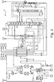
- Air separation plants according to preferred embodiments of the invention are illustrated, respectively labeled 100, 200 and 300.
- the air separation plants 100, 200 and 300 have a number of identically designed components, but in practice they can also be structurally designed differ from each other.
- the air separation plant 100 according to FIG Figure 1 explained; regarding the in the Figures 2 and 3 air separation plants 200 and 300 illustrated below, only the distinguishing features are discussed.
- Air A which has already been pressurized outside the system 100, is provided in the form of a feed air flow a in the air separation plant 100 illustrated.
- This air can, for example, come from a supply network and, for example, be at a pressure of approx. 6 bar. Deviating from the representation according to Figure 1 However, the air A can also be pressurized within the air separation plant 100.
- the feed air A of the feed air flow a is divided into two partial flows b and c after precooling (required in certain cases) in a heat exchanger (not specifically designated), the partial flow b being compressed in an air compressor 101 and the partial flow c in a booster 102.
- a pressure level upstream of the air compressor 101 and the booster 102 is referred to as the “initial pressure level”, while a pressure level downstream of the air compressor 101 and the booster 102 is referred to as the “first pressure level”.
- the air compressor 101 is preferably designed in one stage. As explained above, the predominant portion of the feed air A is compressed in the form of the material flow b in the air compressor 101, but a smaller portion is compressed in the booster 102 in parallel.
- the partial flows b and c are combined in the example shown to form a collective flow d, which is cooled in a basically known manner in a pre-cooling device 103 using cooling water (flow B, return C).
- the cooled feed air flow is further designated by d and then fed to a cleaning device 104, for example comprising a pair of adsorber containers operated in alternation.
- a substream e is fed to a main heat exchanger 105 of the air separation plant 100 (at the first pressure level and a temperature level referred to here as the “first temperature level”).
- the partial flow e is the main heat exchanger 105 taken at a temperature level, which is referred to here as the "second temperature level”.
- the partial flow e is initially still at the first pressure level.
- the partial flow e is subjected to compression in a cold booster 106 at the first pressure level and the second temperature level. This brings it to a higher pressure level, which is referred to here as the "second pressure level”.
- the temperature of the partial flow e increases due to the compression due to the heat of compression introduced, so that the partial flow e is fed back to the main heat exchanger 105 at an intermediate temperature level above the second temperature level.
- the partial flow e is then further cooled in the main heat exchanger 105, specifically to a temperature level which is referred to here as the “third temperature level”.
- the substream e is then fed into a separator 107 and subjected to a phase separation.
- a gas phase in the form of a material flow f and a liquid phase in the form of a material flow g are withdrawn from the separator 107.
- the material flow f is referred to here as the “first process flow”
- the material flow g is correspondingly referred to as the “second process flow”.
- the first process stream comprises non-liquefied, pressurized air as a result of the treatment explained above
- the second process stream g comprises pressurized and liquefied air.
- the first process stream f is expanded in an expansion turbine 108 and fed into a high pressure column 111 of the air separation plant 100.
- the expansion turbine 108 is operated, as explained several times, in such a way that a liquid portion forms at its outlet to a defined extent as explained above.
- the expansion in the expansion turbine 108 takes place to an operating pressure level of the high pressure column 111 or a pressure level present in the high pressure column 111 at the feed point.
- the second process stream g is in the in Figure 1 illustrated example again supplied to the main heat exchanger 105 and removed from this at the cold end.
- the second process stream g is passed through the main heat exchanger 105 with a partial stream h of the material stream d, which passes from the warm to the cold end and through this was liquefied, combined after the second process stream g and the substream h were each expanded in corresponding expansion devices, for example expansion valves, which are not separately designated here.
- the expansion also takes place to a pressure level in the high pressure column 111 or a pressure level which is present at a feed point into the high pressure column 111.
- a material flow formed from the second process flow g and the substream h is designated as a collective flow with the reference symbol i.
- air is also blown into a low-pressure column 112 of the air separation plant 100, for which a basically known Lachmann turbine 109 is used.
- the Lachmann turbine 109 is an expansion turbine that is used in the in Figure 1 illustrated embodiment of the air separation plant 100 is mechanically coupled to the booster 102 already explained above.
- the air expanded in the expansion turbine 109 is a partial flow k of the material flow d, which was previously cooled to an intermediate temperature level in the main heat exchanger 105 (referred to here as the “fourth temperature level”).
- the air of substream k expanded in expansion turbine 109 is fed (see link 2) into low-pressure column 112, as already mentioned.
- the air separation plant 100 has a crude argon column 113 and pure argon column 114 in addition to the high pressure column 111 and the low pressure column 112 in a rectification column system, which is designated as a whole by 110. Operation of the rectification column system 110 is known in the art.
- Air separation plants of the type shown are often described elsewhere, for example at Häring (see above) Figure 2 .3A.
- An air separation plant for using the present invention can be designed in the most varied of ways.
- two gaseous oxygen-rich air products are provided at different pressure levels.
- gaseous fluid is withdrawn from the low-pressure column 112 above its bottom in the form of a stream I, which is heated in the main heat exchanger 105 without further pressure-influencing measures and is provided as a corresponding air product, which is additionally denoted by D here.
- bottom liquid is withdrawn from the low-pressure column 112 in the form of a material flow m, which in the example shown can also be carried out in part as liquid oxygen, here additionally designated with K, in the form of a material flow n from the air separation plant 100 .
- a material flow m which in the example shown can also be carried out in part as liquid oxygen, here additionally designated with K, in the form of a material flow n from the air separation plant 100 .
- K liquid oxygen
- discharge pressure level a higher pressure level
- the main heat exchanger 105 transfers in the main heat exchanger 105 to the gaseous or, depending on the pressure level, supercritical state in the form of a material flow o as a corresponding air product, which is also designated here with E.
- pressurized, gaseous, argon-rich fluid is provided as air product F as shown in the air separation plant 100 shown.
- liquid is withdrawn from the pure argon column 114 in the form of a material flow p and, comparable to the material flow o, is brought to a higher pressure level in an internal compression pump 116, converted to a gaseous or supercritical state in the main heat exchanger 105 and provided in the form of the corresponding air product F.
- the air separation plant 100 can also be used to provide low-pressure nitrogen in the form of an air product G, nitrogen from the top of the high-pressure column 111 in the form of an air product H and impure nitrogen from the top of the low-pressure column 112 in the form of an air product I. Further impure nitrogen can be withdrawn from the low-pressure column 112 in the form of a stream r and used, for example, as a regeneration gas in the cleaning device 104 or in the pre-cooling device 103 and then blown off to the atmosphere X.
- a liquid nitrogen product L be provided.
- the air separation plant 200 according to Figure 2 differs from air separation unit 100 according to Figure 1 in particular because the second process stream g is not further cooled in the main heat exchanger 105 before it is expanded and fed into the low-pressure column.
- the partial flow k expanded in the expansion turbine 109 is only fed to the pressure level of the high pressure column 111; the partial flow k is therefore not blown into the low pressure column but is fed to the high pressure column 111 as a further turbine flow.
Landscapes
- Engineering & Computer Science (AREA)
- Physics & Mathematics (AREA)
- Mechanical Engineering (AREA)
- Thermal Sciences (AREA)
- General Engineering & Computer Science (AREA)
- Health & Medical Sciences (AREA)
- Emergency Medicine (AREA)
- Separation By Low-Temperature Treatments (AREA)
Priority Applications (3)
| Application Number | Priority Date | Filing Date | Title |
|---|---|---|---|
| EP19020068.3A EP3696486A1 (fr) | 2019-02-13 | 2019-02-13 | Procédé et installation de fourniture d'un ou d'une pluralité de produits dérivés de l'air gazeux, riches en oxygène |
| PCT/EP2020/025039 WO2020164799A1 (fr) | 2019-02-13 | 2020-01-30 | Procédé et installation pour fournir un ou plusieurs produits présents dans l'air, gazeux et à teneur élevée en oxygène |
| EP20703140.2A EP3924677A1 (fr) | 2019-02-13 | 2020-01-30 | Procédé et installation pour fournir un ou plusieurs produits présents dans l'air, gazeux et à teneur élevée en oxygène |
Applications Claiming Priority (2)
| Application Number | Priority Date | Filing Date | Title |
|---|---|---|---|
| EP19020067 | 2019-02-13 | ||
| EP19020068.3A EP3696486A1 (fr) | 2019-02-13 | 2019-02-13 | Procédé et installation de fourniture d'un ou d'une pluralité de produits dérivés de l'air gazeux, riches en oxygène |
Publications (1)
| Publication Number | Publication Date |
|---|---|
| EP3696486A1 true EP3696486A1 (fr) | 2020-08-19 |
Family
ID=65440754
Family Applications (2)
| Application Number | Title | Priority Date | Filing Date |
|---|---|---|---|
| EP19020068.3A Withdrawn EP3696486A1 (fr) | 2019-02-13 | 2019-02-13 | Procédé et installation de fourniture d'un ou d'une pluralité de produits dérivés de l'air gazeux, riches en oxygène |
| EP20703140.2A Pending EP3924677A1 (fr) | 2019-02-13 | 2020-01-30 | Procédé et installation pour fournir un ou plusieurs produits présents dans l'air, gazeux et à teneur élevée en oxygène |
Family Applications After (1)
| Application Number | Title | Priority Date | Filing Date |
|---|---|---|---|
| EP20703140.2A Pending EP3924677A1 (fr) | 2019-02-13 | 2020-01-30 | Procédé et installation pour fournir un ou plusieurs produits présents dans l'air, gazeux et à teneur élevée en oxygène |
Country Status (2)
| Country | Link |
|---|---|
| EP (2) | EP3696486A1 (fr) |
| WO (1) | WO2020164799A1 (fr) |
Cited By (2)
| Publication number | Priority date | Publication date | Assignee | Title |
|---|---|---|---|---|
| WO2022263013A1 (fr) * | 2021-06-17 | 2022-12-22 | Linde Gmbh | Procédé et installation permettant de fournir un produit à base d'air gazeux sous pression riche en oxygène |
| WO2023110142A1 (fr) * | 2021-12-13 | 2023-06-22 | Linde Gmbh | Procédé de séparation cryogénique de l'air et installation de séparation d'air |
Families Citing this family (1)
| Publication number | Priority date | Publication date | Assignee | Title |
|---|---|---|---|---|
| CN113758150A (zh) * | 2021-09-18 | 2021-12-07 | 乔治洛德方法研究和开发液化空气有限公司 | 空气的低温分离方法和空气分离装置 |
Citations (11)
| Publication number | Priority date | Publication date | Assignee | Title |
|---|---|---|---|---|
| FR2060184A1 (fr) * | 1969-09-10 | 1971-06-18 | Air Liquide | |
| GB1425450A (en) * | 1972-01-21 | 1976-02-18 | Air Prod & Chem | Air separation |
| JPS54162678A (en) * | 1978-06-14 | 1979-12-24 | Hitachi Ltd | Air separating apparatus taking out liquid product utilizing coldness of lng |
| DE19620453A1 (de) * | 1995-06-01 | 1996-12-05 | Linde Ag | Verfahren und Vorrichtung zur Gaszerlegung bei tiefer Temperatur |
| US5666823A (en) * | 1996-01-31 | 1997-09-16 | Air Products And Chemicals, Inc. | High pressure combustion turbine and air separation system integration |
| US20070209389A1 (en) | 2006-03-10 | 2007-09-13 | Prosser Neil M | Cryogenic air separation system for enhanced liquid production |
| WO2009095188A2 (fr) * | 2008-01-28 | 2009-08-06 | Linde Aktiengesellschaft | Procédé et dispositif de séparation de l'air à basse température |
| WO2015127648A1 (fr) | 2014-02-28 | 2015-09-03 | Praxair Technology, Inc. | Distribution de courant de produit sous pression |
| EP2963367A1 (fr) | 2014-07-05 | 2016-01-06 | Linde Aktiengesellschaft | Procédé et dispositif cryogéniques de séparation d'air avec consommation d'énergie variable |
| EP2980514A1 (fr) | 2014-07-31 | 2016-02-03 | Linde Aktiengesellschaft | Procédé de séparation cryogénique de l'air et installation de séparation d'air |
| FR3058785A1 (fr) * | 2016-11-17 | 2018-05-18 | L'air Liquide, Societe Anonyme Pour L'etude Et L'exploitation Des Procedes Georges Claude | Procede de separation d’air par distillation cryogenique mettant en oeuvre la detente d’un gaz |
Family Cites Families (2)
| Publication number | Priority date | Publication date | Assignee | Title |
|---|---|---|---|---|
| GB864855A (en) * | 1958-05-19 | 1961-04-12 | Air Prod Inc | Improvements in and relating to methods and apparatus for fractionating gaseous mixtures |
| DE102011121314A1 (de) * | 2011-12-16 | 2013-06-20 | Linde Aktiengesellschaft | Verfahren zur Erzeugung eines gasförmigen Sauerstoff-Druckprodukts durch Tieftemperaturzerlegung von Luft |
-
2019
- 2019-02-13 EP EP19020068.3A patent/EP3696486A1/fr not_active Withdrawn
-
2020
- 2020-01-30 WO PCT/EP2020/025039 patent/WO2020164799A1/fr unknown
- 2020-01-30 EP EP20703140.2A patent/EP3924677A1/fr active Pending
Patent Citations (11)
| Publication number | Priority date | Publication date | Assignee | Title |
|---|---|---|---|---|
| FR2060184A1 (fr) * | 1969-09-10 | 1971-06-18 | Air Liquide | |
| GB1425450A (en) * | 1972-01-21 | 1976-02-18 | Air Prod & Chem | Air separation |
| JPS54162678A (en) * | 1978-06-14 | 1979-12-24 | Hitachi Ltd | Air separating apparatus taking out liquid product utilizing coldness of lng |
| DE19620453A1 (de) * | 1995-06-01 | 1996-12-05 | Linde Ag | Verfahren und Vorrichtung zur Gaszerlegung bei tiefer Temperatur |
| US5666823A (en) * | 1996-01-31 | 1997-09-16 | Air Products And Chemicals, Inc. | High pressure combustion turbine and air separation system integration |
| US20070209389A1 (en) | 2006-03-10 | 2007-09-13 | Prosser Neil M | Cryogenic air separation system for enhanced liquid production |
| WO2009095188A2 (fr) * | 2008-01-28 | 2009-08-06 | Linde Aktiengesellschaft | Procédé et dispositif de séparation de l'air à basse température |
| WO2015127648A1 (fr) | 2014-02-28 | 2015-09-03 | Praxair Technology, Inc. | Distribution de courant de produit sous pression |
| EP2963367A1 (fr) | 2014-07-05 | 2016-01-06 | Linde Aktiengesellschaft | Procédé et dispositif cryogéniques de séparation d'air avec consommation d'énergie variable |
| EP2980514A1 (fr) | 2014-07-31 | 2016-02-03 | Linde Aktiengesellschaft | Procédé de séparation cryogénique de l'air et installation de séparation d'air |
| FR3058785A1 (fr) * | 2016-11-17 | 2018-05-18 | L'air Liquide, Societe Anonyme Pour L'etude Et L'exploitation Des Procedes Georges Claude | Procede de separation d’air par distillation cryogenique mettant en oeuvre la detente d’un gaz |
Non-Patent Citations (3)
| Title |
|---|
| "Industrial Gases Processing", 2006, WILEY-VCH |
| "Natural Gas Expansion and Integration with Air Separation Units", IP.COM JOURNAL, IP.COM INC., WEST HENRIETTA, NY, US, 23 September 2003 (2003-09-23), XP013012940, ISSN: 1533-0001 * |
| F.G. KERRY: "Industrial Gas Handbook: Gas Separation and Purification", 2006, CRC PRESS |
Cited By (2)
| Publication number | Priority date | Publication date | Assignee | Title |
|---|---|---|---|---|
| WO2022263013A1 (fr) * | 2021-06-17 | 2022-12-22 | Linde Gmbh | Procédé et installation permettant de fournir un produit à base d'air gazeux sous pression riche en oxygène |
| WO2023110142A1 (fr) * | 2021-12-13 | 2023-06-22 | Linde Gmbh | Procédé de séparation cryogénique de l'air et installation de séparation d'air |
Also Published As
| Publication number | Publication date |
|---|---|
| WO2020164799A1 (fr) | 2020-08-20 |
| EP3924677A1 (fr) | 2021-12-22 |
Similar Documents
| Publication | Publication Date | Title |
|---|---|---|
| EP1067345B1 (fr) | Procédé et dispositif pour la séparation cryogénique des constituants de l'air | |
| WO2016015860A1 (fr) | Procédé de séparation cryogénique de l'air et installation de séparation d'air | |
| WO2007104449A1 (fr) | Procédé et dispositif de décomposition de l'air à basse température | |
| EP3179187B1 (fr) | Procédé de production d'un produit comprime riche en oxygène, gazeux et liquide dans une installation de décomposition de l'air et installation de décomposition de l'air | |
| EP3410050B1 (fr) | Procédé de production d'un ou de plusieurs produits pneumatiques et installation de séparation d'air | |
| EP2963370B1 (fr) | Procede et dispositif cryogeniques de separation d'air | |
| DE102010052545A1 (de) | Verfahren und Vorrichtung zur Gewinnung eines gasförmigen Druckprodukts durch Tieftemperaturzerlegung von Luft | |
| WO2020164799A1 (fr) | Procédé et installation pour fournir un ou plusieurs produits présents dans l'air, gazeux et à teneur élevée en oxygène | |
| WO2021204424A2 (fr) | Procédé de séparation d'air à basse température, installation de séparation d'air et ensemble composé d'au moins deux installations de séparation d'air | |
| EP3290843A2 (fr) | Procédé et dispositif destiné à fabriquer de l'azote pressurisé et liquide par décomposition à basse température de l'air | |
| EP2963369B1 (fr) | Procede et dispositif cryogeniques de separation d'air | |
| WO2011110301A2 (fr) | Procédé et dispositif de séparation de l'air à basse température | |
| DE202021002895U1 (de) | Anlage zur Tieftemperaturzerlegung von Luft | |
| EP3870917B1 (fr) | Procédé et installation de séparation cryogénique d'air | |
| WO2022053173A1 (fr) | Procédé et installation de fractionnement d'air cryogénique | |
| EP1199532A1 (fr) | Système de séparation d'air cryogénique à trois colonnes | |
| WO2019214847A9 (fr) | Procédé pour produire un ou plusieurs produit(s) formés à partir d'air et installation de séparation d'air | |
| EP3870916B1 (fr) | Procédé de production d'un produit ou d'une pluralité de produits de l'air et installation de séparation de l'air | |
| WO2022263013A1 (fr) | Procédé et installation permettant de fournir un produit à base d'air gazeux sous pression riche en oxygène | |
| EP1284403B1 (fr) | Procédé et appareil de production d'oxygène par séparation d'air cryogénique | |
| EP4211409A1 (fr) | Procédé d'obtention d'un ou de plusieurs produits à base d'air, et installation de fractionnement d'air | |
| WO2023051946A1 (fr) | Procédé de séparation cryogénique de l'air et installation de séparation d'air | |
| WO2023030689A1 (fr) | Procédé pour obtenir un ou plusieurs produits de l'air et installation de séparation d'air | |
| WO2018219501A1 (fr) | Procédé pour produire un ou plusieurs produits formés à partir d'air et installation de séparation d'air | |
| WO2021204418A1 (fr) | Procédé de production d'un produit d'azote gazeux et liquide au moyen d'une séparation à basse température de l'air, et système de séparation d'air |
Legal Events
| Date | Code | Title | Description |
|---|---|---|---|
| PUAI | Public reference made under article 153(3) epc to a published international application that has entered the european phase |
Free format text: ORIGINAL CODE: 0009012 |
|
| STAA | Information on the status of an ep patent application or granted ep patent |
Free format text: STATUS: THE APPLICATION HAS BEEN PUBLISHED |
|
| AK | Designated contracting states |
Kind code of ref document: A1 Designated state(s): AL AT BE BG CH CY CZ DE DK EE ES FI FR GB GR HR HU IE IS IT LI LT LU LV MC MK MT NL NO PL PT RO RS SE SI SK SM TR |
|
| AX | Request for extension of the european patent |
Extension state: BA ME |
|
| STAA | Information on the status of an ep patent application or granted ep patent |
Free format text: STATUS: THE APPLICATION IS DEEMED TO BE WITHDRAWN |
|
| 18D | Application deemed to be withdrawn |
Effective date: 20210220 |