EP2961985B1 - Installation de compression d'un réfrigérant - Google Patents
Installation de compression d'un réfrigérant Download PDFInfo
- Publication number
- EP2961985B1 EP2961985B1 EP14703805.3A EP14703805A EP2961985B1 EP 2961985 B1 EP2961985 B1 EP 2961985B1 EP 14703805 A EP14703805 A EP 14703805A EP 2961985 B1 EP2961985 B1 EP 2961985B1
- Authority
- EP
- European Patent Office
- Prior art keywords
- lubricant
- refrigerant compressor
- refrigerant
- compressor system
- pressure stage
- Prior art date
- Legal status (The legal status is an assumption and is not a legal conclusion. Google has not performed a legal analysis and makes no representation as to the accuracy of the status listed.)
- Active
Links
- 239000003507 refrigerant Substances 0.000 title claims description 64
- 239000000314 lubricant Substances 0.000 claims description 90
- 230000001419 dependent effect Effects 0.000 claims description 5
- 210000002105 tongue Anatomy 0.000 description 16
- 238000005461 lubrication Methods 0.000 description 3
- 238000005192 partition Methods 0.000 description 3
- 230000006835 compression Effects 0.000 description 2
- 238000007906 compression Methods 0.000 description 2
- 241000446313 Lamella Species 0.000 description 1
- 238000009825 accumulation Methods 0.000 description 1
- 230000002411 adverse Effects 0.000 description 1
- 230000015572 biosynthetic process Effects 0.000 description 1
- 230000000694 effects Effects 0.000 description 1
- 238000004519 manufacturing process Methods 0.000 description 1
- 230000000149 penetrating effect Effects 0.000 description 1
- 230000000284 resting effect Effects 0.000 description 1
- 238000011144 upstream manufacturing Methods 0.000 description 1
Images


Classifications
-
- F—MECHANICAL ENGINEERING; LIGHTING; HEATING; WEAPONS; BLASTING
- F04—POSITIVE - DISPLACEMENT MACHINES FOR LIQUIDS; PUMPS FOR LIQUIDS OR ELASTIC FLUIDS
- F04B—POSITIVE-DISPLACEMENT MACHINES FOR LIQUIDS; PUMPS
- F04B39/00—Component parts, details, or accessories, of pumps or pumping systems specially adapted for elastic fluids, not otherwise provided for in, or of interest apart from, groups F04B25/00 - F04B37/00
- F04B39/02—Lubrication
- F04B39/0223—Lubrication characterised by the compressor type
- F04B39/0276—Lubrication characterised by the compressor type the pump being of the reciprocating piston type, e.g. oscillating, free-piston compressors
-
- F—MECHANICAL ENGINEERING; LIGHTING; HEATING; WEAPONS; BLASTING
- F04—POSITIVE - DISPLACEMENT MACHINES FOR LIQUIDS; PUMPS FOR LIQUIDS OR ELASTIC FLUIDS
- F04B—POSITIVE-DISPLACEMENT MACHINES FOR LIQUIDS; PUMPS
- F04B37/00—Pumps having pertinent characteristics not provided for in, or of interest apart from, groups F04B25/00 - F04B35/00
- F04B37/10—Pumps having pertinent characteristics not provided for in, or of interest apart from, groups F04B25/00 - F04B35/00 for special use
-
- F—MECHANICAL ENGINEERING; LIGHTING; HEATING; WEAPONS; BLASTING
- F04—POSITIVE - DISPLACEMENT MACHINES FOR LIQUIDS; PUMPS FOR LIQUIDS OR ELASTIC FLUIDS
- F04B—POSITIVE-DISPLACEMENT MACHINES FOR LIQUIDS; PUMPS
- F04B39/00—Component parts, details, or accessories, of pumps or pumping systems specially adapted for elastic fluids, not otherwise provided for in, or of interest apart from, groups F04B25/00 - F04B37/00
- F04B39/02—Lubrication
-
- F—MECHANICAL ENGINEERING; LIGHTING; HEATING; WEAPONS; BLASTING
- F04—POSITIVE - DISPLACEMENT MACHINES FOR LIQUIDS; PUMPS FOR LIQUIDS OR ELASTIC FLUIDS
- F04B—POSITIVE-DISPLACEMENT MACHINES FOR LIQUIDS; PUMPS
- F04B39/00—Component parts, details, or accessories, of pumps or pumping systems specially adapted for elastic fluids, not otherwise provided for in, or of interest apart from, groups F04B25/00 - F04B37/00
- F04B39/12—Casings; Cylinders; Cylinder heads; Fluid connections
- F04B39/121—Casings
-
- F—MECHANICAL ENGINEERING; LIGHTING; HEATING; WEAPONS; BLASTING
- F04—POSITIVE - DISPLACEMENT MACHINES FOR LIQUIDS; PUMPS FOR LIQUIDS OR ELASTIC FLUIDS
- F04B—POSITIVE-DISPLACEMENT MACHINES FOR LIQUIDS; PUMPS
- F04B41/00—Pumping installations or systems specially adapted for elastic fluids
- F04B41/02—Pumping installations or systems specially adapted for elastic fluids having reservoirs
-
- F—MECHANICAL ENGINEERING; LIGHTING; HEATING; WEAPONS; BLASTING
- F04—POSITIVE - DISPLACEMENT MACHINES FOR LIQUIDS; PUMPS FOR LIQUIDS OR ELASTIC FLUIDS
- F04B—POSITIVE-DISPLACEMENT MACHINES FOR LIQUIDS; PUMPS
- F04B41/00—Pumping installations or systems specially adapted for elastic fluids
- F04B41/06—Combinations of two or more pumps
-
- F—MECHANICAL ENGINEERING; LIGHTING; HEATING; WEAPONS; BLASTING
- F04—POSITIVE - DISPLACEMENT MACHINES FOR LIQUIDS; PUMPS FOR LIQUIDS OR ELASTIC FLUIDS
- F04C—ROTARY-PISTON, OR OSCILLATING-PISTON, POSITIVE-DISPLACEMENT MACHINES FOR LIQUIDS; ROTARY-PISTON, OR OSCILLATING-PISTON, POSITIVE-DISPLACEMENT PUMPS
- F04C2/00—Rotary-piston machines or pumps
- F04C2/08—Rotary-piston machines or pumps of intermeshing-engagement type, i.e. with engagement of co-operating members similar to that of toothed gearing
Definitions
- the invention relates to a refrigerant compressor system comprising at least one low pressure stage and at least one high pressure stage, a suction channel leading from a suction connection for the refrigerant to the low pressure stage, an intermediate pressure channel leading from the low pressure stage to the high pressure stage, a high pressure connection connected to the high pressure stage.
- Such refrigerant compressor systems are from GB 1,174,370 A , the U.S. 2,606,430 A and the EP 1 956 319 A1 known.
- each stage has its own oil separator, the oil of which is returned to the respective stage.
- the document EP 1 170 558 discloses a compressor device with compressors operated in parallel, in the first of which the oil from the oil separator is fed to the suction line.
- the invention is therefore based on the object of improving a refrigerant compressor system of the generic type in such a way that a sufficient supply of lubricant is always ensured for the low-pressure stage.
- This object is achieved according to the invention in a refrigerant compressor system of the type described at the outset in that a lubricant bath charged with the intermediate pressure in the intermediate pressure channel is provided, that a lubricant supply device removes lubricant from the lubricant reservoir and supplies it to the refrigerant that is sucked in and flows to the low pressure stage.
- the advantage of the solution according to the invention is that with the lubricant supply device according to the invention there is the possibility of utilizing the pressure gradient between the intermediate pressure and the suction pressure of the refrigerant compressor system and thus of removing lubricant from the To supply the lubricant reservoir to the refrigerant drawn in from the low-pressure stage and thereby ensure sufficient lubrication, in particular of valves in the low-pressure stage.
- the lubricant supply device supplies the lubricant to a suction path of the low-pressure stage running in the system housing, in particular a suction channel and / or a suction chamber of the low-pressure stage, so that the lubricant can be supplied without outside the system housing components to be provided can be realized.
- the suction channel or the suction chamber are also located in the system housing.
- the lubricant supply device comprises a metering unit which meters an amount of lubricant depending on the operating state, so that the metering unit offers the possibility to adjust the amount of lubricant depending on the operating condition.
- the metering unit prevents pressure equalization between the output path and the lubricant bath via the lubricant supply device during or after a compressor standstill.
- the dosing which is dependent on the operating conditions, could take place via a separate control provided for this purpose.
- Another, more advantageous solution provides that the metering unit is controlled by the compressor output, so that it is possible to use the compressor output to detect the operating states and to dose the amount of lubricant in accordance with the compressor output.
- the metering unit could be designed in the most varied of ways.
- the metering unit could be controlled in the most varied of ways depending on the compressor output.
- a particularly simple solution provides that the metering unit is controlled by a compressor shaft and metered the amount of lubricant in accordance with the speed of the compressor shaft.
- the metering unit could be designed as a slide or valve.
- a particularly simple solution provides that the metering unit is designed as a metering pump.
- the metering pump is preferably designed so that it has a speed-dependent delivery volume.
- metering pump is a gear pump.
- a lubricant mass flow supplied to the refrigerant drawn in is a maximum of 5% of the total mass flow of refrigerant and lubricant drawn in by the low-pressure stage.
- the refrigerant compressor system has a system housing on which the metering unit is arranged.
- the dosing unit is preferably arranged in a cover of the system housing, since it can be installed in the system housing in a simple manner, with the dosing unit in particular being integrated into the cover.
- a conveying channel leading from the metering unit to the lubricant reservoir is provided on the system housing, preferably on the cover, in particular in the system housing, preferably in the cover, through which there is the possibility of transferring the lubricant to convey from the lubricant reservoir to the metering unit.
- a conveying channel for the lubricant leading from the metering unit to the suction path is provided on the system housing, in particular in the system housing, so that simple manufacture and assembly is thereby possible.
- the conveying channel can run exclusively in the system housing, for example in a cover of the same.
- the delivery channel runs partly in the system housing and partly in a compressor component, for example in a compressor shaft.
- the bearings for the compressor shaft can preferably also be lubricated in a targeted manner by means of the conveying channel.
- a nozzle for the lubricant to be supplied is assigned to the suction path.
- the solution according to the invention has particular advantages if the refrigerant compressor comprises a reciprocating piston compressor, since a reciprocating piston compressor has suction valves which are particularly sensitive to wear.
- the piston compressor comprises a first cylinder bank to form the low-pressure stage and a second cylinder bank to form the high-pressure stage, so that both the low-pressure stage and the high-pressure stage can be easily separated that they are formed by different cylinder banks of a compressor.
- the lubricant reservoir could be an external reservoir.
- a particularly simple solution provides that the lubricant reservoir is arranged in a drive space of the system housing, the drive for the low-pressure stage and the high-pressure stage being arranged in the drive space.
- the lubricant reservoir is arranged on the bottom side of the drive space.
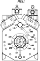
- the refrigerant compressor system 10 shown comprises a system housing designated as a whole by 12, which extends in a longitudinal direction 14.
- the system housing 12 comprises a central housing body 16, which also extends in the longitudinal direction 14 and carries a first end-face cover 22 on a first end face and a second end-face cover 24 on a second end face, which, for example, still has its face facing away from the central housing body 16 Page is still provided with a flange surface 26 for mounting a converter.
- the central housing body 16 comprises, as in FIG Fig. 3 shown, a drive housing section 32 of a reciprocating compressor 40, which encloses a drive space 34, wherein the drive space 34 is between the first end-side cover 22 and an intermediate wall 36 of the central housing body 16, which is located between the drive housing section 32 and a motor housing section 42 of the central housing body 16.
- the motor housing section 42 for accommodating an electric motor 50 comprises a motor compartment 44, which in turn lies between the partition 36 and the second end cover 24, the motor compartment 44 also extending from the motor housing section 42 into the second end cover 24.
- the electric motor designated as a whole by 50, is seated in the motor compartment 44 and comprises a stator 52 arranged in the motor compartment 44 and a rotor 54 enclosed by the stator 52, the rotor 54 being rotatable about an axis of rotation 56.
- the rotor 54 is seated on a compressor shaft of the reciprocating compressor 40, denoted as a whole by 60, which carries the rotor 54 with a rotor support section 62 extending in the engine compartment 44 and supports it so as to be rotatable about the axis of rotation 56.
- the compressor shaft 60 also extends into the drive space 34 and has a drive section 64 which extends through the drive space 34 and carries a plurality of eccentrics 66.
- the compressor shaft 60 is in turn mounted in the system housing 12 in a bearing seat 72 provided on the partition 36 and in a bearing seat 74 provided on the first end cover 22, so that the drive section 64 with the eccentrics 66 lies between the bearing seats 72 and 74 while the rotor support section 62 extends with a free end in the engine compartment 44 starting from the bearing seat 72.
- the drive section 64 of the compressor shaft 60 with its eccentrics 66 serves to drive a plurality of cylinders 82 of the piston compressor 40, which are arranged, for example, in the form of two cylinder banks 84 and 86 in the drive housing section 32, with each of the cylinders 82 has a cylinder chamber 92 in which a piston 94 can be moved in a stroke direction 96, each cylinder chamber 92 being enclosed, for example, by a cylinder liner 98 seated in the drive section.
- Each piston 94 is in turn driven by a connecting rod 102 which, on the one hand, is articulated on the piston 94 and, on the other hand, encloses one of the eccentrics 66.
- each of the cylinder banks 84 and 86 are closed off by a valve plate 104 and 106, the respective valve plate 104 and 106 carrying a cylinder head 112 and 114 on its side facing away from the respective cylinder liner 98.
- the cylinder head 112 is assigned to the first cylinder bank 84 and the cylinder head 114 is assigned to the second cylinder bank 86.
- each of the valve plates 104, 106 and each of the cylinder heads 112 and 114 overlap all of the cylinder spaces 92 of the cylinders 82 of the respective cylinder bank 84 and 86, respectively.
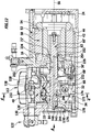
- a suction shut-off valve 122 is provided, which in turn is provided with a suction connection 124, and which is mounted, for example, on the first end cover 22 and supplies refrigerant to be sucked in to a suction channel 126 provided in the first end cover 22 and the drive housing section 32, which leads from the suction shut-off valve 122 extends as far as the first cylinder bank 84, the suction channel 126 penetrating an opening 128 in the drive housing section 32, which is aligned with an opening 132 in the valve plate 104, so that the refrigerant drawn in can exit the drive housing section 32, pass through the valve plate 104 and can enter a suction chamber 134 of the cylinder head 112, as in FIG Fig. 3 , 6th and 7th shown.
- suction channel 126 and the suction chamber 134 form a suction path 130 provided in the system housing 12 for the refrigerant drawn in.
- a simple suction line connection can also be provided, be it by means of a screw connection or a joint connection.
- the suction chamber 134 is located on a side of the respective valve plate 104, 106 facing away from the cylinder chamber 92 and via suction openings 136 arranged in the respective valve plate 104, 106 for all cylinders 82 of the respective cylinder bank 84, 86, with each suction opening on a side facing the cylinder chamber 92 136 is assigned a working valve or suction valve 138, which is arranged, for example, on the valve plate 104 and which comprises a suction lamella or valve tongue 140, which in the in Fig. 7 and 8th
- the closed position shown in solid lines and resting on the valve plate 104, closes the suction opening 136 and is in a position in FIG Fig. 7 and 8th
- the open position shown in dashed lines releases the suction opening 136, so that refrigerant can be sucked into the cylinder chamber 92 through this.
- valve plate 104 To determine the movability of the valve tongue 140, on the one hand, in its closed position, the valve plate 104 and, on the other hand, a guide recess 142 is provided in a cylinder liner collar 144 of the cylinder liner 98, in which the respective valve tongue 140 engages with a tongue tip 146 so that the tongue tip 146 in the guide recess 142 is guided in its movements between its closed and its open position.
- the guide recess 142 is provided with an in particular in Fig. 8 shown stop surface 148 provided, which the maximum open position, the is the maximum distance from the valve plate 104 that defines the valve tongue 140, so that the guide recess 142 forms a lift stop with the stop surface 148.
- the suction chamber 134 is also assigned a pressure chamber 152, which is also formed in the cylinder head 112, a row of outlet valves 154, for example seated on the valve plate 104, being arranged in the pressure chamber 152, which are also capable of To release outlet openings so that compressed refrigerant can enter the pressure chamber 152 from the cylinder space 92.
- the cylinders 82 of the cylinder bank 86 are also designed in the same way as the cylinders 82 of the cylinder bank 84 with the valve plate 104 and 106, the valve plate 106 and the cylinder head 114 in particular also being designed accordingly.
- the refrigerant compressor system works with the two cylinder banks 84 and 86 as a two-stage compressor, that is, refrigerant sucked in by the cylinders 82 of the first cylinder bank 84 forming a low pressure stage 156 at suction pressure PS is first compressed to an intermediate pressure PZ, then into the engine compartment 44 flows in, flows through the engine compartment 44 and enters an intermediate pressure channel 162 of the drive housing section 32 so that the refrigerant at intermediate pressure PZ can enter the suction chamber 134 of the cylinder head 114 of the cylinder bank 86 and from the cylinders 82 of the second cylinder bank, which form a high pressure stage 158 86 is ultimately compressed to high pressure PH, the refrigerant under high pressure PH then being able to exit from high pressure connection 164.
- a lubricant supply device designated as a whole with 170 which consists of a lubricant bath 174 formed over a bottom area 172 of the drive chamber 34 by means of a
- the lubricant is dispensed from the metering unit 180 via an in Fig. 6 as Figures 9 to 11
- the second conveying channel 182 shown in the figure and provided in the first end-side cover 22 and a filter 184 still arranged therein feeds a nozzle 186 directed into the suction channel 126, with which the lubricant can be injected into the suction channel 126 through which the sucked-in refrigerant flows, so that the in the suction channel 126 injected lubricant is entrained by the sucked in refrigerant and is supplied at least to the suction valves 138 for lubrication of the same.
- the pressure difference for conveying the lubricant through the lubricant supply device 170 is already present in that a pressure corresponding to the intermediate pressure PZ is present in the drive chamber 34, which pressure is higher than the suction pressure PS, so that this pressure difference is already used to convey the lubricant from the lubricant bath 174 to the nozzle 186 is sufficient.
- the metering unit 180 therefore does not necessarily have to generate a pressure difference, but rather serves primarily to achieve metering of the lubricant as a function of the output of the refrigerant compressor system, in the simplest case as a function of the speed of the compressor shaft 60.
- This supplied lubricant forms, in particular in the region of the valve plate 104 and the stop surfaces 148 of the guide recesses 142, a lubricant layer through which the valve tongues 140 and of the tongue tips 146 of the valve tongues 140 on the valve plate 104 and / or on the stop surfaces 148 in order to avoid breakouts in the area of the tongue tips 146 and / or the valve tongues 140.
- the dosing unit 180 could be a volume-controlling valve.
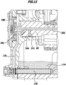
- the metering unit 180 is designed as a metering pump 190 with a speed-dependent, in particular speed-proportional delivery volume, which is coupled to the compressor shaft 60 and is thus driven synchronously with the compressor shaft 60 in order to dose the lubricant injected into the suction channel 126 via the nozzle 148 proportionally to the Make speed of the compressor shaft 60.
- the metering pump 190 is designed as a gear pump, which has an internally toothed outer body 192 and a corresponding externally toothed inner body 194, which is rotatable on the one hand about an axis 196 of an eccentric pin 198, the eccentric pin in turn being arranged eccentrically to the axis of rotation 56 of the compressor shaft 60 and on the compressor shaft 60 is integrally formed so that the inner body 194 of the gear pump 190 is driven directly by the compressor shaft 60.
- the outer body 192 and the inner body 194 are designed relative to one another in such a way that the eccentric revolving of the eccentric pin 198 between the outer body 192 and the inner body 194 creates free spaces 202 which, as a result of the eccentric movement of the eccentric pin 198, revolve around the axis of rotation 56 of the compressor shaft 60 are moved so that lubricant supplied through an inlet pocket 204 through the conveying channel 176 enters the free spaces 202 that are formed and through the Movement of the free spaces 202 about the axis of rotation 56 is conveyed to an outlet pocket 206, which is connected to the conveying channel 182, so that the lubricant can be fed through this to the nozzle 186 directed into the suction channel 126.
- the gear pump 190 is constructed in such a way that, when the eccentric pin 198 is no longer moving around the axis of rotation 56 and the inner body 194 is stationary, it blocks lubricant delivery through the lubricant supply device 170 and thus blocks the supply of lubricant to the suction channel 126 when the compressor shaft 60 is at a standstill.
- the metering pump 190 also blocks a reduction in the pressure in the suction channel 126 when the compressor shaft 60 and thus the inner body 194 are at a standstill, so that lubricant still present in the suction channel 126 via other paths, for example leaks in the area of the pistons 94 of the cylinder banks 84, 86 to the lubricant bath 174 flows back.
- This also has the advantage that it is possible to prevent the suction channel 126 from being flooded with lubricant when the refrigerant compressor system according to the invention is at a standstill and also to maintain the pressure in the suction channel 126 in order to prevent the lubricant in the suction channel 126 from leaking, for example in the area of the To supply cylinder banks 84, 86 to the lubricant bath 104 again and thus to avoid oil hammers when the refrigerant compressor system starts up again.
- the lubricant supply device 170 is integrated in the first end-side cover 22, so that in particular the conveying channel 176 and the conveying channel 182 lie with the nozzle 184 in the first end cover 22 and preferably also the filters 178 and 184 are also seated in the first end cover 22.
- the first cover 22 advantageously also comprises a receptacle 212 for the outer body 192 of the metering pump 190, the inlet pocket 204 and the outlet pocket 206 also opening into this receptacle 212 at the end, in particular between the bearing receptacle 74 and the receptacle 212.
- the outer body 192 can be inserted non-rotatably into the receptacle 212 and the inner body 194 then sits in it, which is rotatably mounted on the eccentric pin 198 in the described manner about the axis 196 and thus rotates with the eccentric pin 198 about the axis of rotation 56.
- FIG Fig. 12 and 13th In a second exemplary embodiment of a refrigerant compressor system according to the invention, shown in FIG Fig. 12 and 13th those features that are identical to that of the first exemplary embodiment are provided with the same reference numerals, so that in this respect reference can also be made in full to the statements relating to the first exemplary embodiment.
- the lubricant bath 174 is provided in the drive space 34, from which the lubricant supply device 170 'takes lubricant, also through the conveying channel 176 provided in the first end-side cover 22.
- the metering unit 180 formed by the metering pump 190, is also provided in the first end-side cover 22 in the same way as in the first exemplary embodiment and is designed in the same way as described in connection with the first exemplary embodiment.
- the metering pump 190 does not convey the lubricant into a conveying channel running further in the first end-side cover 22, but into a compressor shaft channel 222, which preferably runs coaxially to the axis of rotation 56 in the compressor shaft 60 ', from the compressor shaft channel 222 in the area of the bearing seat 72' in the partition 36 ', a transverse channel 224 leads to a receiving groove 226 provided in the bearing seat 72 around the compressor shaft 60', from which a conveying channel 228 in the intermediate wall 36 'and in the drive housing section 32' extends to a nozzle 232 which enters the suction channel 126 'in the drive housing section 32' opens.
- the compressor shaft duct 222 is provided with further transverse ducts, with, for example, a transverse duct 242 serving to lubricate a sliding bearing 244 between the compressor shaft 60 'and the bearing receptacle 74, transverse ducts 246 serving to lubricate sliding bearings 248 between the eccentrics 66 and the connecting rods 102, and transverse ducts 252 serve to lubricate sliding bearings 254 between the compressor shaft 60 'and the bearing seat 72'.
- a transverse duct 242 serving to lubricate a sliding bearing 244 between the compressor shaft 60 'and the bearing receptacle 74
- transverse ducts 246 serving to lubricate sliding bearings 248 between the eccentrics 66 and the connecting rods 102
- transverse ducts 252 serve to lubricate sliding bearings 254 between the compressor shaft 60 'and the bearing seat 72'.
- the lubricant supply device 170 ' thus serves not only to supply lubricant to the suction channel 126' in order to achieve the effects in the area of the suction valves 138 described in connection with the first embodiment, but also to provide bearings 244, 248, 254 in the area of the compressor shaft 60 'to be supplied with lubricant.
Landscapes
- Engineering & Computer Science (AREA)
- Mechanical Engineering (AREA)
- General Engineering & Computer Science (AREA)
- Compressor (AREA)
- Applications Or Details Of Rotary Compressors (AREA)
- Structures Of Non-Positive Displacement Pumps (AREA)
Claims (15)
- Installation de compresseur pour fluide réfrigérant comprenant
au moins un étage à basse pression (156) et au moins un étage à haute pression (158), un canal d'aspiration (126) menant à partir d'un raccord d'aspiration (124) pour le fluide réfrigérant vers l'étage à basse pression (156), un canal de pression intermédiaire (162) menant depuis l'étage à basse pression (156) vers l'étage à haute pression (158), un raccord de haute pression (164) relié à l'étage à haute pression (158),
dans laquelle est prévu un bain de lubrifiant (174) sollicité avec la pression intermédiaire (PZ) dans le canal de pression intermédiaire (162),
caractérisée en ce qu'un dispositif d'amenée de lubrifiant (170) prélève un lubrifiant depuis le bain de lubrifiant constituant un réservoir de lubrifiant (174) et l'amène au fluide réfrigérant aspiré s'écoulant dans un chemin d'aspiration (130) vers l'étage à basse pression (156). - Installation de compresseur pour fluide réfrigérant selon la revendication 1, caractérisée en ce que le dispositif d'amenée de lubrifiant (170) amène le lubrifiant à un chemin d'aspiration (130) de l'étage à basse pression (156) se déroulant dans un logement d'installation (12).
- Installation de compresseur pour fluide réfrigérant selon la revendication 1, caractérisée en ce que l'unité de dosage (180) est commandée par un arbre de compresseur (60).
- Installation de compresseur pour fluide réfrigérant selon l'une des revendications précédentes, caractérisée en ce que l'unité de dosage (180) est conçue en tant que pompe de dosage (190).
- Installation de compresseur pour fluide réfrigérant selon la revendication 4, caractérisée en ce que la pompe de dosage (190) présente un volume transporté dépendant de la vitesse de rotation.
- Installation de compresseur pour fluide réfrigérant selon l'une des revendications précédentes, caractérisée en ce qu'un flux massique de lubrifiant amené au fluide réfrigérant aspiré s'élève au maximum à 5 % du flux massique total de fluide réfrigérant avec lubrifiant aspiré par l'étage à basse pression (156).
- Installation de compresseur pour fluide réfrigérant selon l'une des revendications précédentes, caractérisée en ce que l'installation de compresseur pour fluide réfrigérant présente un logement d'installation (12) contre lequel est agencée l'unité de dosage (180).
- Installation de compresseur pour fluide réfrigérant selon la revendication 7, caractérisée en ce que l'unité de dosage (180) est agencée contre un couvercle (22) du logement d'installation (12).
- Installation de compresseur pour fluide réfrigérant selon la revendication 8, caractérisée en ce que l'unité de dosage (180) est intégrée au couvercle (22).
- Installation de compresseur pour fluide réfrigérant selon la revendication 8 ou 9, caractérisée en ce qu'un canal de transport (176) amenant depuis l'unité de dosage (180) vers le bain de lubrifiant (174) est prévu contre le logement d'installation (12).
- Installation de compresseur pour fluide réfrigérant selon l'une des revendications 8 à 10, caractérisée en ce qu'un canal de transport (182, 228) pour lubrifiant amenant depuis l'unité de dosage (180) vers le chemin d'aspiration (130) est prévu contre le logement d'installation (12).
- Installation de compresseur pour fluide réfrigérant selon l'une des revendications précédentes, caractérisée en ce qu'une buse (184, 232) est attribuée au chemin d'aspiration (130) pour le lubrifiant devant lui être amené.
- Installation de compresseur pour fluide réfrigérant selon l'une des revendications précédentes, caractérisée en ce que l'installation de compresseur pour fluide réfrigérant (10) comprend un compresseur à piston (40).
- Installation de compresseur pour fluide réfrigérant selon la revendication 13, caractérisée en ce que le compresseur à piston (40) comprend une première rangée de cylindres (84) pour la formation de l'étage à basse pression (156) et une seconde rangée de cylindres (86) pour la formation de l'étage à haute pression (158).
- Installation de compresseur pour fluide réfrigérant selon l'une des revendications précédentes, caractérisée en ce que le bain de lubrifiant (174) est agencé dans une chambre d'entraînement (34) du logement d'installation (12) et en ce qu'en particulier le réservoir de lubrifiant (174) est agencé du côté du fond de la chambre d'entraînement (34).
Applications Claiming Priority (2)
| Application Number | Priority Date | Filing Date | Title |
|---|---|---|---|
| DE102013203268.4A DE102013203268A1 (de) | 2013-02-27 | 2013-02-27 | Kältemittelverdichteranlage |
| PCT/EP2014/052212 WO2014131587A1 (fr) | 2013-02-27 | 2014-02-05 | Installation de compression d'un réfrigérant |
Publications (2)
| Publication Number | Publication Date |
|---|---|
| EP2961985A1 EP2961985A1 (fr) | 2016-01-06 |
| EP2961985B1 true EP2961985B1 (fr) | 2021-05-05 |
Family
ID=50073162
Family Applications (1)
| Application Number | Title | Priority Date | Filing Date |
|---|---|---|---|
| EP14703805.3A Active EP2961985B1 (fr) | 2013-02-27 | 2014-02-05 | Installation de compression d'un réfrigérant |
Country Status (7)
| Country | Link |
|---|---|
| US (1) | US20150361972A1 (fr) |
| EP (1) | EP2961985B1 (fr) |
| CN (1) | CN105074210A (fr) |
| BR (1) | BR112015020228A2 (fr) |
| DE (1) | DE102013203268A1 (fr) |
| RU (1) | RU2637608C2 (fr) |
| WO (1) | WO2014131587A1 (fr) |
Families Citing this family (5)
| Publication number | Priority date | Publication date | Assignee | Title |
|---|---|---|---|---|
| EP3440359B1 (fr) * | 2016-04-06 | 2020-10-07 | BITZER Kühlmaschinenbau GmbH | Ensemble compresseur de fluide réfrigérant |
| DE102018129473A1 (de) * | 2018-11-22 | 2020-05-28 | Bitzer Kühlmaschinenbau Gmbh | Kältemittelverdichter |
| DK181078B1 (en) | 2020-02-12 | 2022-11-25 | Maersk Container Ind A/S | FLOW CONDUCTOR FOR A PISTON COMPRESSOR IN A COOLING SYSTEM, PISTON COMPRESSOR FOR A COOLING SYSTEM AND CYLINDER HEAD FOR A PISTON COMPRESSOR FOR A COOLING SYSTEM |
| DE102020103975A1 (de) * | 2020-02-14 | 2021-08-19 | Bitzer Kühlmaschinenbau Gmbh | Kältemittelverdichter |
| DE102022113123A1 (de) * | 2022-05-24 | 2023-11-30 | Bitzer Kühlmaschinenbau Gmbh | Kältemittelverdichtereinheit |
Family Cites Families (22)
| Publication number | Priority date | Publication date | Assignee | Title |
|---|---|---|---|---|
| US2606430A (en) * | 1951-08-24 | 1952-08-12 | Freezing Equipment Sales Inc | Automatic lubrication means for plural stage compressors |
| US2844305A (en) * | 1953-11-03 | 1958-07-22 | Gen Motors Corp | Refrigerating apparatus |
| DE1132286B (de) * | 1959-05-11 | 1962-06-28 | Ingbuero Dipl Ing Friedrich He | Vorrichtung zum Schmieren von ein- oder mehrzylindrigen Stufenkolben-Verdichtern |
| US3131855A (en) * | 1961-12-28 | 1964-05-05 | Vilter Manufacturing Corp | Art of conserving lubricant in gas compressors |
| GB1174370A (en) * | 1968-05-07 | 1969-12-17 | Stal Refrigeration Ab | A Compressor Unit. |
| US3630316A (en) * | 1969-03-07 | 1971-12-28 | Necchi Spa | Lubricating device for enclosed motor compressor units |
| DE2250947A1 (de) * | 1972-10-18 | 1974-05-02 | Bitzer Kuehlmaschinenbau Kg | Verdichter fuer kaeltemaschinen |
| US4586875A (en) * | 1985-06-06 | 1986-05-06 | Thermo King Corporation | Refrigerant compressor bypass oil filter system |
| US4887514A (en) * | 1988-11-18 | 1989-12-19 | Vilter Manufacturing Corporation | Oil separation and gas pressure equalizer means for reciprocating gas compressor |
| DE58907121D1 (de) * | 1989-06-06 | 1994-04-07 | Leybold Ag | Zwei- oder mehrstufige Hochvakuumpumpe. |
| US5236311A (en) * | 1992-01-09 | 1993-08-17 | Tecumseh Products Company | Compressor device for controlling oil level in two-stage high dome compressor |
| US5183134A (en) * | 1992-01-13 | 1993-02-02 | Triangle Engineered Products Co. | Lubrication system for air compressor |
| US5580233A (en) * | 1994-09-16 | 1996-12-03 | Hitachi, Ltd. | Compressor with self-aligning rotational bearing |
| US6141980A (en) * | 1998-02-05 | 2000-11-07 | Shaw; David N. | Evaporator generated foam control of compression systems |
| TWI237682B (en) * | 2000-07-07 | 2005-08-11 | Sanyo Electric Co | Freezing apparatus |
| DE10333402A1 (de) * | 2003-07-16 | 2005-02-10 | Bitzer Kühlmaschinenbau Gmbh | Kompressor |
| JP4640142B2 (ja) * | 2005-11-30 | 2011-03-02 | ダイキン工業株式会社 | 冷凍装置 |
| CN101743404B (zh) * | 2007-08-28 | 2012-10-10 | 三菱电机株式会社 | 旋转压缩机 |
| DE102008004569A1 (de) * | 2008-01-10 | 2009-07-16 | Bitzer Kühlmaschinenbau Gmbh | Hubkolbenverdichter |
| RU2423620C2 (ru) * | 2009-09-29 | 2011-07-10 | Общество с ограниченной ответственностью "Научно-производственное предприятие "Орион ВДМ" (ООО НПП "Орион ВДМ") | Дозирующий шестеренный насос |
| JP5372880B2 (ja) * | 2010-09-22 | 2013-12-18 | 株式会社神戸製鋼所 | 2段圧縮冷凍装置 |
| CN202302667U (zh) * | 2011-11-07 | 2012-07-04 | 重庆气体压缩机厂有限责任公司 | 压缩机油泵机构 |
-
2013
- 2013-02-27 DE DE102013203268.4A patent/DE102013203268A1/de not_active Ceased
-
2014
- 2014-02-05 CN CN201480010906.XA patent/CN105074210A/zh active Pending
- 2014-02-05 WO PCT/EP2014/052212 patent/WO2014131587A1/fr active Application Filing
- 2014-02-05 EP EP14703805.3A patent/EP2961985B1/fr active Active
- 2014-02-05 BR BR112015020228A patent/BR112015020228A2/pt not_active Application Discontinuation
- 2014-02-05 RU RU2015140918A patent/RU2637608C2/ru active
-
2015
- 2015-08-26 US US14/836,617 patent/US20150361972A1/en not_active Abandoned
Also Published As
| Publication number | Publication date |
|---|---|
| BR112015020228A2 (pt) | 2017-07-18 |
| EP2961985A1 (fr) | 2016-01-06 |
| US20150361972A1 (en) | 2015-12-17 |
| RU2015140918A (fr) | 2017-03-31 |
| RU2637608C2 (ru) | 2017-12-05 |
| WO2014131587A1 (fr) | 2014-09-04 |
| CN105074210A (zh) | 2015-11-18 |
| DE102013203268A1 (de) | 2014-08-28 |
Similar Documents
| Publication | Publication Date | Title |
|---|---|---|
| DE1628385C3 (de) | AuBenachsiger Drehkolbenverdichter mit Kämmeingriff und einem Verstellschieber | |
| EP2732165B1 (fr) | Compresseur à vis | |
| DE1528951C3 (de) | Verdrängerpumpe zur Förderung einer stark dampf- und blasenhaltigen Flüssigkeit | |
| EP2961985B1 (fr) | Installation de compression d'un réfrigérant | |
| CH252204A (de) | Hydraulisches Getriebe. | |
| DE102013106344B4 (de) | Kältemittelverdichter | |
| EP2128443B1 (fr) | Elément de pompe | |
| DE102007016145A1 (de) | Flügelzellenpumpe | |
| EP2954192B1 (fr) | Pompe haute pression | |
| WO2020120064A1 (fr) | Pompe à broche hélicoïdale régulable | |
| EP2935857B1 (fr) | Systeme d'injection de carburant a haute pression | |
| DE2402029B2 (de) | Schmiervorrichtung für Rotationskolbenverdichter | |
| EP0509077B1 (fr) | Pompe a pistons, notamment pompe a pistons radiaux | |
| DE2857494A1 (de) | Druckoelschmierung fuer eine vakuumpumpe | |
| DE102010038430B4 (de) | Verdrängerpumpe mit Absaugnut | |
| DE112013005092B4 (de) | Kupplungsbeölung | |
| DE102011075620B4 (de) | Verdrängerpumpe mit einem Bypassventil | |
| WO2020113252A1 (fr) | Système et procédé permettant d'ajuster une longueur active d'une bielle au moyen d'une alimentation en lubrifiant | |
| DE102019112050A1 (de) | Förderpumpe mit einem Leckagekanal | |
| DE102014207070B4 (de) | Pumpe | |
| DE102010040300B4 (de) | Geometrie eines Bypasskanals einer Verdrängerpumpe | |
| DE102009019419B4 (de) | Umlaufverdrängermaschine mit vereinfachter Lagerachse oder -welle | |
| DE102010040302B4 (de) | Öffnungszeitpunkt eines Bypasskanals einer Verdrängerpumpe | |
| DE102006036439A1 (de) | Förderaggregat | |
| DE202008007146U1 (de) | Pumpenelement |
Legal Events
| Date | Code | Title | Description |
|---|---|---|---|
| PUAI | Public reference made under article 153(3) epc to a published international application that has entered the european phase |
Free format text: ORIGINAL CODE: 0009012 |
|
| 17P | Request for examination filed |
Effective date: 20150825 |
|
| AK | Designated contracting states |
Kind code of ref document: A1 Designated state(s): AL AT BE BG CH CY CZ DE DK EE ES FI FR GB GR HR HU IE IS IT LI LT LU LV MC MK MT NL NO PL PT RO RS SE SI SK SM TR |
|
| AX | Request for extension of the european patent |
Extension state: BA ME |
|
| DAX | Request for extension of the european patent (deleted) | ||
| RAP1 | Party data changed (applicant data changed or rights of an application transferred) |
Owner name: BITZER KUEHLMASCHINENBAU GMBH |
|
| GRAP | Despatch of communication of intention to grant a patent |
Free format text: ORIGINAL CODE: EPIDOSNIGR1 |
|
| STAA | Information on the status of an ep patent application or granted ep patent |
Free format text: STATUS: GRANT OF PATENT IS INTENDED |
|
| INTG | Intention to grant announced |
Effective date: 20200814 |
|
| GRAS | Grant fee paid |
Free format text: ORIGINAL CODE: EPIDOSNIGR3 |
|
| GRAA | (expected) grant |
Free format text: ORIGINAL CODE: 0009210 |
|
| STAA | Information on the status of an ep patent application or granted ep patent |
Free format text: STATUS: THE PATENT HAS BEEN GRANTED |
|
| AK | Designated contracting states |
Kind code of ref document: B1 Designated state(s): AL AT BE BG CH CY CZ DE DK EE ES FI FR GB GR HR HU IE IS IT LI LT LU LV MC MK MT NL NO PL PT RO RS SE SI SK SM TR |
|
| REG | Reference to a national code |
Ref country code: GB Ref legal event code: FG4D Free format text: NOT ENGLISH |
|
| REG | Reference to a national code |
Ref country code: CH Ref legal event code: EP |
|
| REG | Reference to a national code |
Ref country code: AT Ref legal event code: REF Ref document number: 1390132 Country of ref document: AT Kind code of ref document: T Effective date: 20210515 |
|
| REG | Reference to a national code |
Ref country code: DE Ref legal event code: R096 Ref document number: 502014015541 Country of ref document: DE |
|
| REG | Reference to a national code |
Ref country code: IE Ref legal event code: FG4D Free format text: LANGUAGE OF EP DOCUMENT: GERMAN |
|
| REG | Reference to a national code |
Ref country code: LT Ref legal event code: MG9D |
|
| PG25 | Lapsed in a contracting state [announced via postgrant information from national office to epo] |
Ref country code: HR Free format text: LAPSE BECAUSE OF FAILURE TO SUBMIT A TRANSLATION OF THE DESCRIPTION OR TO PAY THE FEE WITHIN THE PRESCRIBED TIME-LIMIT Effective date: 20210505 Ref country code: FI Free format text: LAPSE BECAUSE OF FAILURE TO SUBMIT A TRANSLATION OF THE DESCRIPTION OR TO PAY THE FEE WITHIN THE PRESCRIBED TIME-LIMIT Effective date: 20210505 Ref country code: LT Free format text: LAPSE BECAUSE OF FAILURE TO SUBMIT A TRANSLATION OF THE DESCRIPTION OR TO PAY THE FEE WITHIN THE PRESCRIBED TIME-LIMIT Effective date: 20210505 Ref country code: BG Free format text: LAPSE BECAUSE OF FAILURE TO SUBMIT A TRANSLATION OF THE DESCRIPTION OR TO PAY THE FEE WITHIN THE PRESCRIBED TIME-LIMIT Effective date: 20210805 |
|
| PG25 | Lapsed in a contracting state [announced via postgrant information from national office to epo] |
Ref country code: LV Free format text: LAPSE BECAUSE OF FAILURE TO SUBMIT A TRANSLATION OF THE DESCRIPTION OR TO PAY THE FEE WITHIN THE PRESCRIBED TIME-LIMIT Effective date: 20210505 Ref country code: GR Free format text: LAPSE BECAUSE OF FAILURE TO SUBMIT A TRANSLATION OF THE DESCRIPTION OR TO PAY THE FEE WITHIN THE PRESCRIBED TIME-LIMIT Effective date: 20210806 Ref country code: IS Free format text: LAPSE BECAUSE OF FAILURE TO SUBMIT A TRANSLATION OF THE DESCRIPTION OR TO PAY THE FEE WITHIN THE PRESCRIBED TIME-LIMIT Effective date: 20210905 Ref country code: SE Free format text: LAPSE BECAUSE OF FAILURE TO SUBMIT A TRANSLATION OF THE DESCRIPTION OR TO PAY THE FEE WITHIN THE PRESCRIBED TIME-LIMIT Effective date: 20210505 Ref country code: RS Free format text: LAPSE BECAUSE OF FAILURE TO SUBMIT A TRANSLATION OF THE DESCRIPTION OR TO PAY THE FEE WITHIN THE PRESCRIBED TIME-LIMIT Effective date: 20210505 Ref country code: NO Free format text: LAPSE BECAUSE OF FAILURE TO SUBMIT A TRANSLATION OF THE DESCRIPTION OR TO PAY THE FEE WITHIN THE PRESCRIBED TIME-LIMIT Effective date: 20210805 Ref country code: PL Free format text: LAPSE BECAUSE OF FAILURE TO SUBMIT A TRANSLATION OF THE DESCRIPTION OR TO PAY THE FEE WITHIN THE PRESCRIBED TIME-LIMIT Effective date: 20210505 Ref country code: PT Free format text: LAPSE BECAUSE OF FAILURE TO SUBMIT A TRANSLATION OF THE DESCRIPTION OR TO PAY THE FEE WITHIN THE PRESCRIBED TIME-LIMIT Effective date: 20210906 Ref country code: ES Free format text: LAPSE BECAUSE OF FAILURE TO SUBMIT A TRANSLATION OF THE DESCRIPTION OR TO PAY THE FEE WITHIN THE PRESCRIBED TIME-LIMIT Effective date: 20210505 |
|
| REG | Reference to a national code |
Ref country code: NL Ref legal event code: MP Effective date: 20210505 |
|
| PG25 | Lapsed in a contracting state [announced via postgrant information from national office to epo] |
Ref country code: NL Free format text: LAPSE BECAUSE OF FAILURE TO SUBMIT A TRANSLATION OF THE DESCRIPTION OR TO PAY THE FEE WITHIN THE PRESCRIBED TIME-LIMIT Effective date: 20210505 |
|
| PG25 | Lapsed in a contracting state [announced via postgrant information from national office to epo] |
Ref country code: RO Free format text: LAPSE BECAUSE OF FAILURE TO SUBMIT A TRANSLATION OF THE DESCRIPTION OR TO PAY THE FEE WITHIN THE PRESCRIBED TIME-LIMIT Effective date: 20210505 Ref country code: SM Free format text: LAPSE BECAUSE OF FAILURE TO SUBMIT A TRANSLATION OF THE DESCRIPTION OR TO PAY THE FEE WITHIN THE PRESCRIBED TIME-LIMIT Effective date: 20210505 Ref country code: SK Free format text: LAPSE BECAUSE OF FAILURE TO SUBMIT A TRANSLATION OF THE DESCRIPTION OR TO PAY THE FEE WITHIN THE PRESCRIBED TIME-LIMIT Effective date: 20210505 Ref country code: DK Free format text: LAPSE BECAUSE OF FAILURE TO SUBMIT A TRANSLATION OF THE DESCRIPTION OR TO PAY THE FEE WITHIN THE PRESCRIBED TIME-LIMIT Effective date: 20210505 Ref country code: EE Free format text: LAPSE BECAUSE OF FAILURE TO SUBMIT A TRANSLATION OF THE DESCRIPTION OR TO PAY THE FEE WITHIN THE PRESCRIBED TIME-LIMIT Effective date: 20210505 Ref country code: CZ Free format text: LAPSE BECAUSE OF FAILURE TO SUBMIT A TRANSLATION OF THE DESCRIPTION OR TO PAY THE FEE WITHIN THE PRESCRIBED TIME-LIMIT Effective date: 20210505 |
|
| REG | Reference to a national code |
Ref country code: DE Ref legal event code: R097 Ref document number: 502014015541 Country of ref document: DE |
|
| PLBE | No opposition filed within time limit |
Free format text: ORIGINAL CODE: 0009261 |
|
| STAA | Information on the status of an ep patent application or granted ep patent |
Free format text: STATUS: NO OPPOSITION FILED WITHIN TIME LIMIT |
|
| 26N | No opposition filed |
Effective date: 20220208 |
|
| PG25 | Lapsed in a contracting state [announced via postgrant information from national office to epo] |
Ref country code: IS Free format text: LAPSE BECAUSE OF FAILURE TO SUBMIT A TRANSLATION OF THE DESCRIPTION OR TO PAY THE FEE WITHIN THE PRESCRIBED TIME-LIMIT Effective date: 20210905 Ref country code: AL Free format text: LAPSE BECAUSE OF FAILURE TO SUBMIT A TRANSLATION OF THE DESCRIPTION OR TO PAY THE FEE WITHIN THE PRESCRIBED TIME-LIMIT Effective date: 20210505 |
|
| PG25 | Lapsed in a contracting state [announced via postgrant information from national office to epo] |
Ref country code: MC Free format text: LAPSE BECAUSE OF FAILURE TO SUBMIT A TRANSLATION OF THE DESCRIPTION OR TO PAY THE FEE WITHIN THE PRESCRIBED TIME-LIMIT Effective date: 20210505 |
|
| REG | Reference to a national code |
Ref country code: CH Ref legal event code: PL |
|
| REG | Reference to a national code |
Ref country code: BE Ref legal event code: MM Effective date: 20220228 |
|
| PG25 | Lapsed in a contracting state [announced via postgrant information from national office to epo] |
Ref country code: LU Free format text: LAPSE BECAUSE OF NON-PAYMENT OF DUE FEES Effective date: 20220205 |
|
| PG25 | Lapsed in a contracting state [announced via postgrant information from national office to epo] |
Ref country code: LI Free format text: LAPSE BECAUSE OF NON-PAYMENT OF DUE FEES Effective date: 20220228 Ref country code: IE Free format text: LAPSE BECAUSE OF NON-PAYMENT OF DUE FEES Effective date: 20220205 Ref country code: CH Free format text: LAPSE BECAUSE OF NON-PAYMENT OF DUE FEES Effective date: 20220228 |
|
| PG25 | Lapsed in a contracting state [announced via postgrant information from national office to epo] |
Ref country code: BE Free format text: LAPSE BECAUSE OF NON-PAYMENT OF DUE FEES Effective date: 20220228 |
|
| REG | Reference to a national code |
Ref country code: AT Ref legal event code: MM01 Ref document number: 1390132 Country of ref document: AT Kind code of ref document: T Effective date: 20220205 |
|
| PG25 | Lapsed in a contracting state [announced via postgrant information from national office to epo] |
Ref country code: AT Free format text: LAPSE BECAUSE OF NON-PAYMENT OF DUE FEES Effective date: 20220205 |
|
| PGFP | Annual fee paid to national office [announced via postgrant information from national office to epo] |
Ref country code: FR Payment date: 20230223 Year of fee payment: 10 |
|
| PGFP | Annual fee paid to national office [announced via postgrant information from national office to epo] |
Ref country code: TR Payment date: 20230117 Year of fee payment: 10 Ref country code: IT Payment date: 20230220 Year of fee payment: 10 |
|
| P01 | Opt-out of the competence of the unified patent court (upc) registered |
Effective date: 20230517 |
|
| PG25 | Lapsed in a contracting state [announced via postgrant information from national office to epo] |
Ref country code: HU Free format text: LAPSE BECAUSE OF FAILURE TO SUBMIT A TRANSLATION OF THE DESCRIPTION OR TO PAY THE FEE WITHIN THE PRESCRIBED TIME-LIMIT; INVALID AB INITIO Effective date: 20140205 |
|
| PG25 | Lapsed in a contracting state [announced via postgrant information from national office to epo] |
Ref country code: MK Free format text: LAPSE BECAUSE OF FAILURE TO SUBMIT A TRANSLATION OF THE DESCRIPTION OR TO PAY THE FEE WITHIN THE PRESCRIBED TIME-LIMIT Effective date: 20210505 Ref country code: CY Free format text: LAPSE BECAUSE OF FAILURE TO SUBMIT A TRANSLATION OF THE DESCRIPTION OR TO PAY THE FEE WITHIN THE PRESCRIBED TIME-LIMIT Effective date: 20210505 |
|
| PGFP | Annual fee paid to national office [announced via postgrant information from national office to epo] |
Ref country code: DE Payment date: 20240228 Year of fee payment: 11 Ref country code: GB Payment date: 20240220 Year of fee payment: 11 |