EP2961985B1 - Refrigerant compressor system - Google Patents
Refrigerant compressor system Download PDFInfo
- Publication number
- EP2961985B1 EP2961985B1 EP14703805.3A EP14703805A EP2961985B1 EP 2961985 B1 EP2961985 B1 EP 2961985B1 EP 14703805 A EP14703805 A EP 14703805A EP 2961985 B1 EP2961985 B1 EP 2961985B1
- Authority
- EP
- European Patent Office
- Prior art keywords
- lubricant
- refrigerant compressor
- refrigerant
- compressor system
- pressure stage
- Prior art date
- Legal status (The legal status is an assumption and is not a legal conclusion. Google has not performed a legal analysis and makes no representation as to the accuracy of the status listed.)
- Active
Links
- 239000003507 refrigerant Substances 0.000 title claims description 64
- 239000000314 lubricant Substances 0.000 claims description 90
- 230000001419 dependent effect Effects 0.000 claims description 5
- 210000002105 tongue Anatomy 0.000 description 16
- 238000005461 lubrication Methods 0.000 description 3
- 238000005192 partition Methods 0.000 description 3
- 230000006835 compression Effects 0.000 description 2
- 238000007906 compression Methods 0.000 description 2
- 241000446313 Lamella Species 0.000 description 1
- 238000009825 accumulation Methods 0.000 description 1
- 230000002411 adverse Effects 0.000 description 1
- 230000015572 biosynthetic process Effects 0.000 description 1
- 230000000694 effects Effects 0.000 description 1
- 238000004519 manufacturing process Methods 0.000 description 1
- 230000000149 penetrating effect Effects 0.000 description 1
- 230000000284 resting effect Effects 0.000 description 1
- 238000011144 upstream manufacturing Methods 0.000 description 1
Images


Classifications
-
- F—MECHANICAL ENGINEERING; LIGHTING; HEATING; WEAPONS; BLASTING
- F04—POSITIVE - DISPLACEMENT MACHINES FOR LIQUIDS; PUMPS FOR LIQUIDS OR ELASTIC FLUIDS
- F04B—POSITIVE-DISPLACEMENT MACHINES FOR LIQUIDS; PUMPS
- F04B39/00—Component parts, details, or accessories, of pumps or pumping systems specially adapted for elastic fluids, not otherwise provided for in, or of interest apart from, groups F04B25/00 - F04B37/00
- F04B39/02—Lubrication
- F04B39/0223—Lubrication characterised by the compressor type
- F04B39/0276—Lubrication characterised by the compressor type the pump being of the reciprocating piston type, e.g. oscillating, free-piston compressors
-
- F—MECHANICAL ENGINEERING; LIGHTING; HEATING; WEAPONS; BLASTING
- F04—POSITIVE - DISPLACEMENT MACHINES FOR LIQUIDS; PUMPS FOR LIQUIDS OR ELASTIC FLUIDS
- F04B—POSITIVE-DISPLACEMENT MACHINES FOR LIQUIDS; PUMPS
- F04B37/00—Pumps having pertinent characteristics not provided for in, or of interest apart from, groups F04B25/00 - F04B35/00
- F04B37/10—Pumps having pertinent characteristics not provided for in, or of interest apart from, groups F04B25/00 - F04B35/00 for special use
-
- F—MECHANICAL ENGINEERING; LIGHTING; HEATING; WEAPONS; BLASTING
- F04—POSITIVE - DISPLACEMENT MACHINES FOR LIQUIDS; PUMPS FOR LIQUIDS OR ELASTIC FLUIDS
- F04B—POSITIVE-DISPLACEMENT MACHINES FOR LIQUIDS; PUMPS
- F04B39/00—Component parts, details, or accessories, of pumps or pumping systems specially adapted for elastic fluids, not otherwise provided for in, or of interest apart from, groups F04B25/00 - F04B37/00
- F04B39/02—Lubrication
-
- F—MECHANICAL ENGINEERING; LIGHTING; HEATING; WEAPONS; BLASTING
- F04—POSITIVE - DISPLACEMENT MACHINES FOR LIQUIDS; PUMPS FOR LIQUIDS OR ELASTIC FLUIDS
- F04B—POSITIVE-DISPLACEMENT MACHINES FOR LIQUIDS; PUMPS
- F04B39/00—Component parts, details, or accessories, of pumps or pumping systems specially adapted for elastic fluids, not otherwise provided for in, or of interest apart from, groups F04B25/00 - F04B37/00
- F04B39/12—Casings; Cylinders; Cylinder heads; Fluid connections
- F04B39/121—Casings
-
- F—MECHANICAL ENGINEERING; LIGHTING; HEATING; WEAPONS; BLASTING
- F04—POSITIVE - DISPLACEMENT MACHINES FOR LIQUIDS; PUMPS FOR LIQUIDS OR ELASTIC FLUIDS
- F04B—POSITIVE-DISPLACEMENT MACHINES FOR LIQUIDS; PUMPS
- F04B41/00—Pumping installations or systems specially adapted for elastic fluids
- F04B41/02—Pumping installations or systems specially adapted for elastic fluids having reservoirs
-
- F—MECHANICAL ENGINEERING; LIGHTING; HEATING; WEAPONS; BLASTING
- F04—POSITIVE - DISPLACEMENT MACHINES FOR LIQUIDS; PUMPS FOR LIQUIDS OR ELASTIC FLUIDS
- F04B—POSITIVE-DISPLACEMENT MACHINES FOR LIQUIDS; PUMPS
- F04B41/00—Pumping installations or systems specially adapted for elastic fluids
- F04B41/06—Combinations of two or more pumps
-
- F—MECHANICAL ENGINEERING; LIGHTING; HEATING; WEAPONS; BLASTING
- F04—POSITIVE - DISPLACEMENT MACHINES FOR LIQUIDS; PUMPS FOR LIQUIDS OR ELASTIC FLUIDS
- F04C—ROTARY-PISTON, OR OSCILLATING-PISTON, POSITIVE-DISPLACEMENT MACHINES FOR LIQUIDS; ROTARY-PISTON, OR OSCILLATING-PISTON, POSITIVE-DISPLACEMENT PUMPS
- F04C2/00—Rotary-piston machines or pumps
- F04C2/08—Rotary-piston machines or pumps of intermeshing-engagement type, i.e. with engagement of co-operating members similar to that of toothed gearing
Description
Die Erfindung betrifft eine Kältemittelverdichteranlage umfassend mindestens eine Niederdruckstufe und mindestens eine Hochdruckstufe, einen ausgehend von einem Sauganschluss für das Kältemittel zu der Niederdruckstufe führenden Saugkanal, einen von der Niederdruckstufe zu der Hochdruckstufe führenden Zwischendruckkanal, einen mit der Hochdruckstufe verbundenen Hochdruckanschluss.The invention relates to a refrigerant compressor system comprising at least one low pressure stage and at least one high pressure stage, a suction channel leading from a suction connection for the refrigerant to the low pressure stage, an intermediate pressure channel leading from the low pressure stage to the high pressure stage, a high pressure connection connected to the high pressure stage.
Derartige Kältemittelverdichteranlagen sind aus der
Aus dem Dokument
Das Dokument
Bei diesen hat sich das Problem ergeben, dass in der Niederdruckstufe, insbesondere bei Ventilen derselben, Schäden auftreten, da zumindest in einzelnen Betriebszuständen nicht ausreichend Schmiermittel zur Verfügung steht.In these, the problem has arisen that damage occurs in the low-pressure stage, in particular in the valves of the same, since there is not enough lubricant available, at least in individual operating states.
Der Erfindung liegt daher die Aufgabe zugrunde, eine Kältemittelverdichteranlage der gattungsgemäßen Art derart zu verbessern, dass stets eine ausreichende Schmiermittelversorgung für die Niederdruckstufe gewährleistet ist. Diese Aufgabe wird bei einer Kältemittelverdichteranlage der eingangs beschriebenen Art erfindungsgemäß dadurch gelöst, dass ein mit dem Zwischendruck im Zwischendruckkanal beaufschlagtes Schmiermittelbad vorgesehen ist, dass eine Schmiermittelzufuhreinrichtung Schmiermittel aus dem Schmiermittelreservoir entnimmt und dem zur Niederdruckstufe strömenden angesaugten Kältemittel zuführt.The invention is therefore based on the object of improving a refrigerant compressor system of the generic type in such a way that a sufficient supply of lubricant is always ensured for the low-pressure stage. This object is achieved according to the invention in a refrigerant compressor system of the type described at the outset in that a lubricant bath charged with the intermediate pressure in the intermediate pressure channel is provided, that a lubricant supply device removes lubricant from the lubricant reservoir and supplies it to the refrigerant that is sucked in and flows to the low pressure stage.
Der Vorteil der erfindungsgemäßen Lösung ist darin zu sehen, dass mit der erfindungsgemäßen Schmiermittelzufuhreinrichtung die Möglichkeit besteht, das Druckgefälle zwischen dem Zwischendruck und dem Saugdruck der Kältemittelverdichteranlage auszunutzen und somit Schmiermittel aus dem Schmiermittelreservoir dem angesaugten Kältemittel der Niederdruckstufe zuzuführen und dadurch für eine ausreichende Schmierung, insbesondere von Ventilen der Niederdruckstufe zu sorgen.The advantage of the solution according to the invention is that with the lubricant supply device according to the invention there is the possibility of utilizing the pressure gradient between the intermediate pressure and the suction pressure of the refrigerant compressor system and thus of removing lubricant from the To supply the lubricant reservoir to the refrigerant drawn in from the low-pressure stage and thereby ensure sufficient lubrication, in particular of valves in the low-pressure stage.
Grundsätzlich wäre die Zufuhr von Schmiermittel an beliebigen Stellen denkbar, solange die Zufuhr zu dem angesaugten Kältemittel erfolgt.In principle, the supply of lubricant at any point would be conceivable as long as the supply takes place to the refrigerant that is sucked in.
Um jedoch das Schmiermittel möglichst günstig der Niederdruckstufe zuzuführen, ist vorzugsweise vorgesehen, dass die Schmiermittelzufuhreinrichtung das Schmiermittel einem im Anlagengehäuse verlaufenden Ansaugpfad der Niederdruckstufe, insbesondere einem Saugkanal und/oder einer Saugkammer der Niederdruckstufe, zuführt, so dass die Zufuhr des Schmiermittels ohne außerhalb des Anlagengehäuse vorzusehende Komponenten realisiert werden kann.However, in order to supply the lubricant to the low-pressure stage as cheaply as possible, it is preferably provided that the lubricant supply device supplies the lubricant to a suction path of the low-pressure stage running in the system housing, in particular a suction channel and / or a suction chamber of the low-pressure stage, so that the lubricant can be supplied without outside the system housing components to be provided can be realized.
Insbesondere liegen auch der Saugkanal oder die Saugkammer in dem Anlagengehäuse.In particular, the suction channel or the suction chamber are also located in the system housing.
Um dabei die Menge des dem angesaugten Kältemittel zugeführten Schmiermittels nicht zu groß werden zu lassen, sondern stets in sinnvollen Grenzen zu halten, ist vorzugsweise vorgesehen, dass die Schmiermittelzufuhreinrichtung eine Dosiereinheit umfasst, welche eine Schmiermittelmenge betriebszustandsabhängig dosiert, so dass mit der Dosiereinheit die Möglichkeit besteht, die Schmiermittelmenge betriebszustandsabhängig anzupassen.In order not to let the amount of lubricant supplied to the sucked-in refrigerant become too large, but rather to keep it within reasonable limits, it is preferably provided that the lubricant supply device comprises a metering unit which meters an amount of lubricant depending on the operating state, so that the metering unit offers the possibility to adjust the amount of lubricant depending on the operating condition.
Beispielsweise ist vorgesehen, verschiedene Betriebszustände und /oder Betriebszustandsbereiche zu definieren und mit der Dosiereinheit je nach Betriebszustand und/oder Betriebszustandsbereich die Schmiermittelmenge zu dosieren.For example, it is provided to define different operating states and / or operating state ranges and to dose the amount of lubricant with the metering unit depending on the operating state and / or operating state range.
Hinsichtlich der Dosierung in den einzelnen Betriebszuständen ist es günstig, wenn bei einem Verdichterstillstand die Zufuhr von Schmiermittel durch die Dosiereinheit gestoppt wird, um somit eine Ansammlung von Schmiermittel im Ansaugpfad zu vermeiden.With regard to the metering in the individual operating states, it is advantageous if the supply of lubricant by the metering unit is stopped when the compressor is at a standstill, in order to avoid an accumulation of lubricant in the suction path.
Ferner ist es von Vorteil, wenn bei oder ab einem Verdichterstillstand die Dosiereinheit einen Druckausgleich zwischen dem Ausgangspfad und dem Schmiermittelbad über die Schmiermittelzufuhreinrichtung verhindert.It is also advantageous if the metering unit prevents pressure equalization between the output path and the lubricant bath via the lubricant supply device during or after a compressor standstill.
Dadurch ist es möglich, durch die im Ansaugpfad aufrechterhaltene Druckdifferenz sich in diesem sammelndes Schmiermittel über Leckagepfade, beispielsweise im Bereich der jeweiligen Druckstufen, in das Schmiermittelbad zurückzuführen und somit bei einem Neustart der Kältemittelverdichteranlage Ölschläge, insbesondere im Bereich der Arbeitsventile, zu vermeiden.This makes it possible, through the pressure difference maintained in the suction path, to return lubricant that collects in this via leakage paths, for example in the area of the respective pressure levels, to the lubricant bath and thus to avoid oil hammers, especially in the area of the working valves, when the refrigerant compressor system is restarted.
Die von Betriebszuständen abhängige Dosierung könnte über eine hierzu vorgesehene separate Steuerung erfolgen.The dosing, which is dependent on the operating conditions, could take place via a separate control provided for this purpose.
Eine andere vorteilhaftere Lösung sieht vor, dass die Dosiereinheit verdichterleistungsgesteuert ist, so dass die Möglichkeit besteht, durch die Verdichterleistung die Betriebszustände zu erfassen und die Schmiermittelmenge entsprechend der Verdichterleistung zu dosieren.Another, more advantageous solution provides that the metering unit is controlled by the compressor output, so that it is possible to use the compressor output to detect the operating states and to dose the amount of lubricant in accordance with the compressor output.
Grundsätzlich könnte dabei die Dosiereinheit in unterschiedlichster Art und Weise ausgebildet sein.In principle, the metering unit could be designed in the most varied of ways.
Beispielsweise könnte die Dosiereinheit in unterschiedlichster Art und Weise abhängig von der Verdichterleistung gesteuert werden.For example, the metering unit could be controlled in the most varied of ways depending on the compressor output.
Beispielsweise bestünde die Möglichkeit, die Verdichterleistung durch eine Steuerung eines Antriebsmotors für die Kältemittelverdichteranlage zu steuern und entsprechend der Steuerung des Antriebsmotors mit dieser Steuerung auch die Dosiereinheit elektronisch zu steuern.For example, it would be possible to control the compressor output by controlling a drive motor for the refrigerant compressor system and to electronically control the metering unit in accordance with the control of the drive motor with this controller.
Eine besonders einfache Lösung sieht jedoch vor, dass die Dosiereinheit durch eine Verdichterwelle gesteuert ist und entsprechend der Drehzahl der Verdichterwelle die Schmiermittelmenge dosiert.A particularly simple solution, however, provides that the metering unit is controlled by a compressor shaft and metered the amount of lubricant in accordance with the speed of the compressor shaft.
Hinsichtlich der Ausbildung der Dosiereinheit selbst wurden keine näheren Angaben gemacht.With regard to the design of the metering unit itself, no further details were given.
So könnte beispielsweise die Dosiereinheit als Schieber oder Ventil ausgebildet sein.For example, the metering unit could be designed as a slide or valve.
Eine besonders einfache Lösung sieht vor, dass die Dosiereinheit als Dosierpumpe ausgebildet ist.A particularly simple solution provides that the metering unit is designed as a metering pump.
Mit einer derartigen Dosierpumpe besteht in einfacher Art und Weise die Möglichkeit, eine leistungsabhängige Dosierung vorzunehmen.With such a metering pump, there is a simple possibility of performing a performance-dependent metering.
Insbesondere ist die Dosierpumpe vorzugsweise so ausgebildet, dass sie ein drehzahlabhängiges Fördervolumen aufweist.In particular, the metering pump is preferably designed so that it has a speed-dependent delivery volume.
Besonders einfach ist dies realisierbar, wenn die Dosierpumpe durch die Verdichterwelle gesteuert, insbesondere angetrieben ist.This can be implemented in a particularly simple manner if the metering pump is controlled, in particular driven, by the compressor shaft.
Hinsichtlich der Dosierpumpe selbst wurden bislang keine näheren Angaben gemacht.With regard to the metering pump itself, no further details have been given so far.
So sieht eine vorteilhafte Lösung vor, dass die Dosierpumpe eine Zahnradpumpe ist.An advantageous solution provides that the metering pump is a gear pump.
Hinsichtlich des dem angesaugten Kältemittel zugeführten Schmiermittelmassenstroms ist vorzugsweise vorgesehen, diesen nicht allzu groß werden zu lassen, da ansonsten die Verdichterleistung und/oder die Standfestigkeit der Kältemittelverdichteranlage beeinträchtigt wird, da beispielsweise eine Ölverpressung in den Arbeitsräumen zu einer erhöhten Antriebsbelastung führt.With regard to the lubricant mass flow supplied to the refrigerant that is sucked in, provision is preferably made not to let it become too large, since otherwise the compressor performance and / or the stability of the Refrigerant compressor system is adversely affected because, for example, oil compression in the work rooms leads to an increased drive load.
Aus diesem Grund ist vorzugsweise vorgesehen, dass ein dem angesaugten Kältemittel zugeführter Schmiermittelmassenstrom maximal 5% des von der Niederdruckstufe angesaugten Gesamtmassenstroms aus Kältemittel und Schmiermittel beträgt.For this reason, it is preferably provided that a lubricant mass flow supplied to the refrigerant drawn in is a maximum of 5% of the total mass flow of refrigerant and lubricant drawn in by the low-pressure stage.
Hinsichtlich der Anordnung der Dosiereinheit wurden bislang keine näheren Angaben gemacht.With regard to the arrangement of the dosing unit, no details have been given so far.
So ist vorzugsweise vorgesehen, dass die Kältemittelverdichteranlage ein Anlagegehäuse aufweist, an welchem die Dosiereinheit angeordnet ist.It is preferably provided that the refrigerant compressor system has a system housing on which the metering unit is arranged.
Vorzugsweise ist dabei die Dosiereinheit in einem Deckel des Anlagegehäuses angeordnet, da sie sich dabei in einfacher Weise in das Anlagegehäuse einbauen lässt, wobei insbesondere die Dosiereinheit in den Deckel integriert ist.The dosing unit is preferably arranged in a cover of the system housing, since it can be installed in the system housing in a simple manner, with the dosing unit in particular being integrated into the cover.
Um die Schmiermittelzufuhreinrichtung möglichst einfach und geschützt ausbilden zu können, ist an dem Anlagengehäuse, vorzugsweise an dem Deckel, insbesondere in dem Anlagengehäuse, vorzugsweise in dem Deckel, ein von der Dosiereinheit zu dem Schmiermittelreservoir führender Förderkanal vorgesehen, durch welchen die Möglichkeit besteht, das Schmiermittel von dem Schmiermittelreservoir zur Dosiereinheit zu fördern.In order to be able to design the lubricant supply device as simply and protected as possible, a conveying channel leading from the metering unit to the lubricant reservoir is provided on the system housing, preferably on the cover, in particular in the system housing, preferably in the cover, through which there is the possibility of transferring the lubricant to convey from the lubricant reservoir to the metering unit.
Ferner ist es zweckmäßig, wenn an dem Anlagengehäuse, insbesondere in dem Anlagengehäuse, ein von der Dosiereinheit zum Ansaugpfad führender Förderkanal für das Schmiermittel vorgesehen ist, so dass dadurch eine einfache Herstellung und Montage möglich ist.It is also expedient if a conveying channel for the lubricant leading from the metering unit to the suction path is provided on the system housing, in particular in the system housing, so that simple manufacture and assembly is thereby possible.
Der Förderkanal kann dabei ausschließlich im Anlagengehäuse, beispielsweise in einem Deckel desselben, verlaufen.The conveying channel can run exclusively in the system housing, for example in a cover of the same.
Es besteht aber auch die Möglichkeit, dass der Förderkanal teilweise im Anlagengehäuse und teilweise in einer Verdichterkomponente, beispielsweise in einer Verdichterwelle verläuft.However, there is also the possibility that the delivery channel runs partly in the system housing and partly in a compressor component, for example in a compressor shaft.
In letztgenanntem Fall kann vorzugsweise mittels des Förderkanals auch noch eine gezielte Schmierung von Lagern für die Verdichterwelle erfolgen.In the latter case, the bearings for the compressor shaft can preferably also be lubricated in a targeted manner by means of the conveying channel.
Insbesondere ist es zum Zuführen des Schmiermittels zu dem angesaugten Kältemittelstrom günstig, wenn dem Ansaugpfad eine Düse für das diesem zuzuführende Schmiermittel zugeordnet ist.In particular, for supplying the lubricant to the sucked-in refrigerant flow, it is advantageous if a nozzle for the lubricant to be supplied is assigned to the suction path.
Hinsichtlich der Art der Verdichtung des Kältemittels in der Kältemittelverdichteranlage wurden im Zusammenhang mit den bisherigen Ausführungsbeispielen keine weiteren Angaben gemacht.With regard to the type of compression of the refrigerant in the refrigerant compressor system, no further details have been given in connection with the previous exemplary embodiments.
So wäre es prinzipiell denkbar, jede Art von Verdichter, beispielsweise Scroll-Verdichter oder Schrauben-Verdichter vorzusehen.In principle, it would be conceivable to provide any type of compressor, for example scroll compressors or screw compressors.
Die erfindungsgemäße Lösung weist jedoch besondere Vorteile auf, wenn der Kältemittelverdichter einen Hub-Kolbenverdichter umfasst, da ein Hub-Kolbenverdichter Ansaugventile aufweist, die besonders verschleißempfindlich sind.However, the solution according to the invention has particular advantages if the refrigerant compressor comprises a reciprocating piston compressor, since a reciprocating piston compressor has suction valves which are particularly sensitive to wear.
Ferner hat es sich bei der Ausbildung einer Niederdruckstufe und einer Hochdruckstufe als vorteilhaft erwiesen, wenn der Kolbenverdichter zur Bildung der Niederdruckstufe eine erste Zylinderbank und zur Bildung der Hochdruckstufe eine zweite Zylinderbank umfasst, so dass sowohl die Niederdruckstufe als auch die Hochdruckstufe einfach dadurch getrennt werden können, dass sie durch verschiedene Zylinderbänke eines Verdichters gebildet werden.Furthermore, it has proven to be advantageous in the formation of a low-pressure stage and a high-pressure stage if the piston compressor comprises a first cylinder bank to form the low-pressure stage and a second cylinder bank to form the high-pressure stage, so that both the low-pressure stage and the high-pressure stage can be easily separated that they are formed by different cylinder banks of a compressor.
Ferner sind hinsichtlich der Anordnung des Schmiermittelreservoirs keine näheren Angaben gemacht worden.Furthermore, no further details have been given with regard to the arrangement of the lubricant reservoir.
Beispielsweise könnte das Schmiermittelreservoir ein externes Reservoir sein.For example, the lubricant reservoir could be an external reservoir.
Eine besonders einfache Lösung sieht jedoch vor, dass das Schmiermittelreservoir in einem Antriebsraum des Anlagengehäuses angeordnet ist, wobei in dem Antriebsraum der Antrieb für die Niederdruckstufe und die Hochdruckstufe angeordnet ist.A particularly simple solution, however, provides that the lubricant reservoir is arranged in a drive space of the system housing, the drive for the low-pressure stage and the high-pressure stage being arranged in the drive space.
Insbesondere ist dabei vorgesehen, dass das Schmiermittelreservoir bodenseitig des Antriebsraums angeordnet ist.In particular, it is provided that the lubricant reservoir is arranged on the bottom side of the drive space.
Weitere Merkmale und Vorteile der Erfindung sind Gegenstand der nachfolgenden Beschreibung sowie der zeichnerischen Darstellung einiger Ausführungsbeispiele.Further features and advantages of the invention are the subject matter of the following description and the graphic representation of some exemplary embodiments.
In der Zeichnung zeigen:
- Fig. 1
- eine Seitenansicht einer erfindungsgemäßen Kältemittelverdichteranlage;
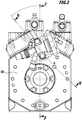
- Fig. 2
- eine Ansicht der Kältemittelverdichteranlage in Richtung des Pfeils A in
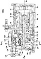
Fig. 1 ; - Fig. 3
- einen Schnitt längs Linie 3-3 in
Fig. 2 ; - Fig. 4
- einen Schnitt längs Linie 4-4 in
Fig. 3 ; - Fig. 5
- einen Schnitt längs Linie 5-5 in
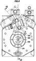
Fig. 2 ; - Fig. 6
- einen Schnitt längs Linie 6-6 in
Fig. 2 ; - Fig. 7
- einen Schnitt längs Linie 7-7 in
Fig. 6 mit ausschnittsweiser Darstellung des Zylinderkopfes, der Ventilplatte und der Zylinderbüchsen einer Zylinderbank; - Fig. 8
- eine vergrößerte Darstellung des Schnitts in
Fig. 6 im Bereich der Ventilplatte und des Ansaugventils; - Fig. 9
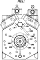
- eine Draufsicht in Richtung des Pfeils A in
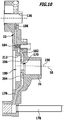
Fig. 3 ; - Fig. 10
- einen Schnitt längs Linie 10-10 in
Fig. 9 ; - Fig. 11
- eine Ansicht entsprechend
Fig. 9 mit Draufsicht auf eine Dosierpumpe gemäß dem ersten Ausführungsbeispiel; - Fig. 12
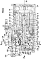
- einen Längsschnitt ähnlich
Fig. 3 durch ein zweites Ausführungsbeispiel einer erfindungsgemäßen Kältemittelverdichteranlage und; - Fig. 13
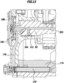
- einen Schnitt ähnlich
Fig. 10 durch das zweite Ausführungsbeispiel der erfindungsgemäßen Kältemittelverdichteranlage.
- Fig. 1
- a side view of a refrigerant compressor system according to the invention;
- Fig. 2
- a view of the refrigerant compressor system in the direction of arrow A in
Fig. 1 ; - Fig. 3
- cut along line 3-3 in
Fig. 2 ; - Fig. 4
- cut along line 4-4 in
Fig. 3 ; - Fig. 5
- a cut along line 5-5 in
Fig. 2 ; - Fig. 6
- cut along line 6-6 in
Fig. 2 ; - Fig. 7
- a section along line 7-7 in
Fig. 6 with partial representation of the cylinder head, the valve plate and the cylinder liners of a cylinder bank; - Fig. 8
- an enlarged view of the section in
Fig. 6 in the area of the valve plate and the suction valve; - Fig. 9
- a plan view in the direction of arrow A in FIG
Fig. 3 ; - Fig. 10
- cut along line 10-10 in
Fig. 9 ; - Fig. 11
- a view accordingly
Fig. 9 with a plan view of a metering pump according to the first embodiment; - Fig. 12
- a longitudinal section similar
Fig. 3 by a second embodiment of a refrigerant compressor system according to the invention and; - Fig. 13
- a cut similar
Fig. 10 by the second embodiment of the refrigerant compressor system according to the invention.
Ein Ausführungsbeispiel einer in
Das Anlagengehäuse 12 umfasst dabei einen zentralen Gehäusekörper 16, welcher sich ebenfalls in der Längsrichtung 14 erstreckt und an einer ersten Stirnseite einen ersten stirnseitigen Deckel 22 sowie an einer zweiten Stirnseite einen zweiten stirnseitigen Deckel 24 trägt, welcher beispielsweise noch auf seiner dem zentralen Gehäusekörper 16 abgewandten Seite noch mit einer Flanschfläche 26 zur Montage eines Umrichters versehen ist.The
Der zentrale Gehäusekörper 16 umfasst, wie in
Der Motorgehäuseabschnitt 42 zur Aufnahme eines Elektromotors 50 umfasst einen Motorraum 44, der seinerseits wiederum zwischen der Zwischenwand 36 und dem zweiten stirnseitigen Deckel 24 liegt, wobei sich der Motorraum 44 auch noch von dem Motorgehäuseabschnitt 42 in den zweiten stirnseitigen Deckel 24 hineinerstreckt.The
In dem Motorraum 44 sitzt der als Ganzes mit 50 bezeichnete Elektromotor, welcher einen im Motorraum 44 angeordneten Stator 52 sowie einen vom Stator 52 umschlossenen Rotor 54 umfasst, wobei der Rotor 54 um eine Drehachse 56 drehbar ist.The electric motor, designated as a whole by 50, is seated in the
Hierzu sitzt der Rotor 54 auf einer als Ganzes mit 60 bezeichneten Verdichterwelle des Kolbenverdichters 40, welche mit einem sich im Motorraum 44 erstreckenden Rotorträgerabschnitt 62 den Rotor 54 trägt und diesen um die Drehachse 56 drehbar lagert. Die Verdichterwelle 60 erstreckt sich aber auch noch in den Antriebsraum 34 hinein und weist einen den Antriebsraum 34 durchsetzenden Antriebsabschnitt 64 auf, der mehrere Exzenter 66 trägt.For this purpose, the
Die Verdichterwelle 60 ist ihrerseits in dem Anlagengehäuse 12 in einer an der Zwischenwand 36 vorgesehenen Lageraufnahme 72 und in einer an dem ersten stirnseitigen Deckel 22 vorgesehenen Lageraufnahme 74 gelagert, so dass der Antriebsabschnitt 64 mit den Exzentern 66 zwischen den Lageraufnahmen 72 und 74 liegt, während sich der Rotorträgerabschnitt 62 ausgehend von der Lageraufnahme 72 mit einem freien Ende im Motorraum 44 erstreckt.The
Wie in
Jeder Kolben 94 wird seinerseits durch ein Pleuel 102 angetrieben, das einerseits gelenkig am Kolben 94 gelagert ist und andererseits einen der Exzenter 66 umschließt.Each
Die Zylinderräume 92 jeder der Zylinderbänke 84 und 86 sind durch eine Ventilplatte 104 bzw. 106 abgeschlossen, wobei die jeweilige Ventilplatte 104 bzw. 106 auf ihrer der jeweiligen Zylinderbüchse 98 abgewandten Seite einen Zylinderkopf 112 bzw. 114 trägt.The
Der Zylinderkopf 112 ist der ersten Zylinderbank 84 zugeordnet ist und der Zylinderkopf 114 ist der zweiten Zylinderbank 86 zugeordnet.The
Beispielsweise übergreifen jede der Ventilplatten 104, 106 und jeder der Zylinderköpfe 112 und 114 sämtliche Zylinderräume 92 der Zylinder 82 der jeweiligen Zylinderbank 84 bzw. 86.For example, each of the
Bei der erfindungsgemäßen Kältemittelverdichteranlage 10 ist, wie in
Insbesondere bilden der Saugkanal 126 und die Saugkammer 134 einen im Anlagengehäuse 12 vorgesehenen Ansaugpfad 130 für das angesaugte Kältemittel.In particular, the
Anstelle des Saugabsperrventils 122 kann aber auch ein einfacher Saugleitungsanschluss, sei es durch eine Verschraubung oder eine Fügeverbindung vorgesehen sein.Instead of the suction shut-off
Die Saugkammer 134 liegt auf einer dem Zylinderraum 92 abgewandten Seite der jeweiligen Ventilplatte 104, 106 und über in der jeweiligen Ventilplatte 104, 106 angeordneten Saugöffnungen 136 für alle Zylinder 82 der jeweiligen Zylinderbank 84, 86, wobei auf einer dem Zylinderraum 92 zugewandten Seite jeder Saugöffnung 136 ein Arbeitsventil oder Saugventil 138 zugeordnet ist, welches beispielsweise an der Ventilplatte 104 angeordnet ist und welches eine Sauglamelle oder Ventilzunge 140 umfasst, die in der in
Zur Festlegung der Bewegbarkeit der Ventilzunge 140 dient einerseits in deren geschlossener Stellung die Ventilplatte 104 und andererseits ist beispielsweise in einem Zylinderbüchsenkragen 144 der Zylinderbüchse 98 eine Führungsausnehmung 142 vorgesehen, in welche die jeweilige Ventilzunge 140 mit einer Zungenspitze 146 eingreift, so dass die Zungenspitze 146 in der Führungsausnehmung 142 bei ihren Bewegungen zwischen ihrer geschlossenen und ihrer offenen Stellung geführt ist.To determine the movability of the
Zur Festlegung der maximal geöffneten Stellung der Ventilzunge 140 ist die Führungsausnehmung 142 mit einer insbesondere in
In dem jeweiligen Zylinderkopf, in
In gleicher Weise wie die Zylinder 82 der Zylinderbank 84 mit der Ventilplatte 104 und 106 sind auch die Zylinder 82 der Zylinderbank 86 ausgebildet, wobei insbesondere auch die Ventilplatte 106 und der Zylinderkopf 114 entsprechend ausgebildet sind.The
Wie insbesondere in
Um Beschädigungen der Saugventile 138 zu vermeiden, die sich beispielsweise darin äußern, dass die Ventilzungen 140, insbesondere im Bereich ihrer Zungenspitzen 146, im Laufe der Zeit Ausbrüche zeigen, die durch Anschlagen der Ventilzungen 140 und/oder der Zungenspitze 146 an der Ventilplatte 104 und/oder den Anschlagflächen 148 zumindest zum Teil entstehen, ist eine als Ganzes mit 170 bezeichnete Schmiermittelzufuhreinrichtung vorgesehen, welche aus einem sich über einen Bodenbereich 172 des Antriebsraums 34 bildenden Schmiermittelbad 174 mittels eines beispielsweise im ersten stirnseitigen Deckel 22 vorgesehenen ersten Förderkanals 176 sowie eines diesem vorgeschalteten Filters 178 Schmiermittel entnimmt und dieses über den Förderkanal 176 einer Dosiereinheit 180 zuführt (
Von der Dosiereinheit 180 wird das Schmiermittel über einen in
Die Druckdifferenz zur Förderung des Schmiermittels durch die Schmiermittelzufuhreinrichtung 170 ist bereits dadurch vorhanden, dass in dem Antriebsraum 34 ein dem Zwischendruck PZ entsprechender Druck vorhanden ist, der höher ist als der Saugdruck PS, so dass diese Druckdifferenz bereits zur Förderung des Schmiermittels von dem Schmiermittelbad 174 zu der Düse 186 ausreichend ist.The pressure difference for conveying the lubricant through the
Die Dosiereinheit 180 muss somit nicht notwendigerweise eine Druckdifferenz erzeugen, sondern dient primär dazu, eine Dosierung des Schmiermittels in Abhängigkeit von einer Leistung der Kältemittelverdichteranlage, im einfachsten Fall abhängig von einer Drehzahl der Verdichterwelle 60, zu erreichen.The
Dieses zugeführte Schmiermittel bildet insbesondere im Bereich der Ventilplatte 104 und der Anschlagflächen 148 der Führungsausnehmungen 142 eine Schmiermittelauflage, durch welche ein Anschlagen der Ventilzungen 140 und der Zungenspitzen 146 der Ventilzungen 140 an der Ventilplatte 104 und/oder an den Anschlagflächen 148 gedämpft wird, um somit Ausbrüche im Bereich der Zungenspitzen 146 und/oder der Ventilzungen 140 zu vermeiden.This supplied lubricant forms, in particular in the region of the
Die Dosiereinheit 180 könnte, um diese möglichst einfach zu gestalten, ein mengensteuerndes Ventil sein.In order to make it as simple as possible, the
Insbesondere ist die Dosiereinheit 180 als Dosierpumpe 190 mit einem drehzahlabhängigen, insbesondere drehzahlproportionalen Fördervolumen ausgebildet, die mit der Verdichterwelle 60 gekoppelt ist und somit synchron mit der Verdichterwelle 60 angetrieben wird, um die Dosierung des über die Düse 148 in den Saugkanal 126 eingespritzten Schmiermittels proportional zur Drehzahl der Verdichterwelle 60 zu gestalten.In particular, the
Wie in
Dabei sind der Außenkörper 192 und der Innenkörper 194 so relativ zueinander ausgebildet, dass sich durch das exzentrische Umlaufen des Exzenterzapfens 198 zwischen dem Außenkörper 192 und dem Innenkörper 194 Freiräume 202 bilden, die durch die Exzenterbewegung des Exzenterzapfens 198 um die Drehachse 56 der Verdichterwelle 60 umlaufend bewegt werden, so dass durch eine Einlasstasche 204 durch den Förderkanal 176 zugeführtes Schmiermittel in die sich bildenden Freiräume 202 eintritt und durch die Bewegung der Freiräume 202 um die Drehachse 56 zu einer Auslasstasche 206 gefördert wird, welche mit dem Förderkanal 182 verbunden ist, so dass durch diesen das Schmiermittel der in den Saugkanal 126 hinein gerichteten Düse 186 zugeführt werden kann.The
Die Zahnradpumpe 190 ist dabei so aufgebaut, dass diese bei sich nicht mehr um die Drehachse 56 herum bewegendem Exzenterzapfen 198 und somit stillstehendem Innenkörper 194 eine Schmiermittelförderung durch die Schmiermittelzufuhreinrichtung 170 blockiert und somit bei stillstehender Verdichterwelle 60 eine Zufuhr von Schmiermittel zu dem Saugkanal 126 blockiert.The
Dies hat den Vorteil, dass bei einem Stillstand des Antriebs der Verdichterwelle 60 und somit auch bei einem Stillstand der Kolben 94 kein Schmiermittel mehr von dem Schmiermittelbad 174 in den Saugkanal 126 einströmen kann, da die Dosierpumpe 190 dies verhindert.This has the advantage that when the drive of the
Ferner blockiert die Dosierpumpe 190 aber auch einen Abbau des Drucks im Saugkanal 126 bei stillstehender Verdichterwelle 60 und somit stillstehendem Innenkörper 194, so dass noch im Saugkanal 126 vorhandenes Schmiermittel über andere Pfade, beispielsweise Leckagen im Bereich der Kolben 94 der Zylinderbänke 84, 86 zum Schmiermittelbad 174 zurückfließt.Furthermore, the
Dies hat außerdem den Vorteil, dass damit die Möglichkeit besteht, bei einem Stillstand der erfindungsgemäßen Kältemittelverdichteranlage eine Überflutung des Saugkanals 126 mit Schmiermittel zu verhindern und außerdem auch den Druck im Saugkanal 126 aufrechtzuerhalten, um das Schmiermittel im Saugkanal 126 über Leckagen, beispielsweise im Bereich der Zylinderbänke 84, 86 dem Schmiermittelbad 104 wieder zuzuführen und somit bei einem Neuanlaufen der Kältemittelverdichteranlage Ölschläge zu vermeiden.This also has the advantage that it is possible to prevent the
Bei dem ersten Ausführungsbeispiel der erfindungsgemäßen Lösung ist die Schmiermittelzufuhreinrichtung 170 in den ersten stirnseitigen Deckel 22 integriert, so dass insbesondere der Förderkanal 176 und der Förderkanal 182 mit der Düse 184 in dem ersten stirnseitigen Deckel 22 liegen und vorzugsweise auch die Filter 178 und 184 ebenfalls in dem ersten stirnseitigen Deckel 22 sitzen.In the first exemplary embodiment of the solution according to the invention, the
Darüber hinaus umfasst vorteilhafterweise der erste Deckel 22 auch eine Aufnahme 212 für den Außenkörper 192 der Dosierpumpe 190, wobei in diese Aufnahme 212 auch die Einlasstasche 204 sowie die Auslasstasche 206 stirnseitig, insbesondere zwischen der Lageraufnahme 74 und der Aufnahme 212 einmünden.In addition, the
In die Aufnahme 212 lässt sich der Außenkörper 192 drehfest einsetzen und in diesem sitzt dann der Innenkörper 194, welcher auf dem Exzenterzapfen 198 in der beschriebenen Art und Weise um die Achse 196 drehbar gelagert ist und somit mit dem Exzenterzapfen 198 um die Drehachse 56 umläuft.The
Bei einem zweiten Ausführungsbeispiel einer erfindungsgemäßen Kältemittelverdichteranlage, dargestellt in den
Insbesondere ist in gleicher Weise wie beim ersten Ausführungsbeispiel in dem Antriebsraum 34 das Schmiermittelbad 174 vorgesehen, aus welchem die Schmiermittelzufuhreinrichtung 170' Schmiermittel entnimmt und zwar ebenfalls durch den in dem ersten stirnseitigen Deckel 22 vorgesehenen Förderkanal 176.In particular, in the same way as in the first exemplary embodiment, the
Ferner ist ebenfalls in gleicher Weise wie beim ersten Ausführungsbeispiel in dem ersten stirnseitigen Deckel 22 die Dosiereinheit 180, gebildet durch die Dosierpumpe 190, vorgesehen und in gleicher Weise wie im Zusammenhang mit dem ersten Ausführungsbeispiel beschrieben ausgebildet.Furthermore, the
Allerdings fördert die Dosierpumpe 190 das Schmiermittel nicht in einen weiter im ersten stirnseitigen Deckel 22 verlaufenden Förderkanal, sondern in einen vorzugsweise koaxial zur Drehachse 56 in der Verdichterwelle 60' verlaufenden Verdichterwellenkanal 222, wobei von dem Verdichterwellenkanal 222 im Bereich der Lageraufnahme 72' in der Zwischenwand 36' ein Querkanal 224 zu einer in der Lageraufnahme 72 vorgesehenen um die Verdichterwelle 60' umlaufenden Aufnahmenut 226 führt, von welcher wiederum ein Förderkanal 228 in der Zwischenwand 36' und im Antriebsgehäuseabschnitt 32' bis zu einer Düse 232 verläuft, welche in den Saugkanal 126' im Antriebsgehäuseabschnitt 32' mündet.However, the
Ferner ist der Verdichterwellenkanal 222 mit weiteren Querkanälen versehen, wobei beispielsweise ein Querkanal 242 zur Schmierung eines Gleitlagers 244 zwischen der Verdichterwelle 60' und der Lageraufnahme 74 dient, Querkanäle 246 zur Schmierung von Gleitlagern 248 zwischen den Exzentern 66 und den Pleueln 102 dienen und Querkanäle 252 zur Schmierung von Gleitlagern 254 zwischen der Verdichterwelle 60' und der Lageraufnahme 72' dienen.Furthermore, the
Damit dient die erfindungsgemäße Schmiermittelzufuhreinrichtung 170' nicht nur dazu, dem Saugkanal 126' Schmiermittel zuzuführen, um die im Zusammenhang mit dem ersten Ausführungsbeispiel beschriebenen Effekte im Bereich der Saugventile 138 zu erreichen, sondern auch dazu, Lager 244, 248, 254 im Bereich der Verdichterwelle 60' mit Schmiermittel zu versorgen.The lubricant supply device 170 'according to the invention thus serves not only to supply lubricant to the suction channel 126' in order to achieve the effects in the area of the
Bei dem zweiten Ausführungsbeispiel werden, abgesehen von der Schmierung der verschiedenen Gleitlager, dieselben Vorteile erreicht, wie im Zusammenhang mit dem ersten Ausführungsbeispiel im Detail beschrieben.In the second exemplary embodiment, apart from the lubrication of the various plain bearings, the same advantages are achieved as described in detail in connection with the first exemplary embodiment.
Claims (15)
- A refrigerant compressor system, comprising at least one low-pressure stage (156) and at least one high-pressure stage (158), a suction duct (126) leading from a suction connection (124) for the refrigerant to the low-pressure stage (156), an intermediate-pressure duct (162) leading from the low-pressure stage (156) to the high-pressure stage (158), a high-pressure connection (164) connected to the high-pressure stage (158), wherein there is provided a lubricant bath (174) to which the intermediate pressure (PZ) in the intermediate-pressure duct (162) is applied,
characterized in that a lubricant feed device (170) draws lubricant from the lubricant bath representing a lubricant reservoir (174) and feeds said lubricant to the induced refrigerant flowing to the low-pressure stage (156) in an intake path (130). - The refrigerant compressor as claimed in claim 1, characterized in that the lubricant feed device (170) feeds the lubricant to an intake path (130) of the low-pressure stage (156) which extends in the system housing (12).
- The refrigerant compressor system as claimed in claim 1, characterized in that the dispensing unit (180) is controlled by a compressor shaft (60).
- The refrigerant compressor system as claimed in one of the preceding claims, characterized in that the dispensing unit (180) is designed as a dispensing pump (190).
- The refrigerant compressor system as claimed in claim 4, characterized in that the dispensing pump (190) has a speed-dependent delivery volume.
- The refrigerant compressor system as claimed in one of the preceding claims, characterized in that a lubricant mass flow fed to the induced refrigerant makes up at most 5% of the total mass flow of refrigerant with lubricant drawn in by the low-pressure stage (156).
- The refrigerant compressor system as claimed in one of the preceding claims, characterized in that the refrigerant compressor system has a system housing (12) on which the dispensing unit (180) is arranged.
- The refrigerant compressor system as claimed in claim 7, characterized in that the dispensing unit (180) is arranged on a cover (22) of the system housing (12).
- The refrigerant compressor system as claimed in claim 8, characterized in that the dispensing unit (180) is integrated into the cover (22).
- The refrigerant compressor system as claimed in claim 8 or 9, characterized in that a delivery duct (176) leading from the dispensing unit (180) to the lubricant reservoir (174) is provided on the system housing (12).
- The refrigerant compressor system as claimed in one of claims 8 to 10, characterized in that a delivery duct (182, 228) for lubricant leading from the dispensing unit (180) to the intake path (130) is provided on the system housing (12).
- The refrigerant compressor system as claimed in one of the preceding claims, characterized in that a nozzle (184, 232) for the lubricant to be fed to the intake path (130) is associated with said intake path.
- The refrigerant compressor system as claimed in one of the preceding claims, characterized in that the refrigerant compressor system (10) comprises a piston compressor (40).
- The refrigerant compressor system as claimed in claim 13, characterized in that the piston compressor (40) comprises a first cylinder bank (84) to form the low-pressure stage (156) and a second cylinder bank (86) to form the high-pressure stage (158).
- The refrigerant compressor system as claimed in one of the preceding claims, characterized in that the lubricant bath (174) is arranged in a drive space (34) of the system housing (12) and in that in particular that the lubricant reservoir (174) is arranged at the bottom of the drive space (34).
Applications Claiming Priority (2)
| Application Number | Priority Date | Filing Date | Title |
|---|---|---|---|
| DE102013203268.4A DE102013203268A1 (en) | 2013-02-27 | 2013-02-27 | Refrigerant compressor |
| PCT/EP2014/052212 WO2014131587A1 (en) | 2013-02-27 | 2014-02-05 | Refrigerant compressor system |
Publications (2)
| Publication Number | Publication Date |
|---|---|
| EP2961985A1 EP2961985A1 (en) | 2016-01-06 |
| EP2961985B1 true EP2961985B1 (en) | 2021-05-05 |
Family
ID=50073162
Family Applications (1)
| Application Number | Title | Priority Date | Filing Date |
|---|---|---|---|
| EP14703805.3A Active EP2961985B1 (en) | 2013-02-27 | 2014-02-05 | Refrigerant compressor system |
Country Status (7)
| Country | Link |
|---|---|
| US (1) | US20150361972A1 (en) |
| EP (1) | EP2961985B1 (en) |
| CN (1) | CN105074210A (en) |
| BR (1) | BR112015020228A2 (en) |
| DE (1) | DE102013203268A1 (en) |
| RU (1) | RU2637608C2 (en) |
| WO (1) | WO2014131587A1 (en) |
Families Citing this family (5)
| Publication number | Priority date | Publication date | Assignee | Title |
|---|---|---|---|---|
| CN109072921B (en) * | 2016-04-06 | 2021-03-26 | 比泽尔制冷设备有限公司 | Refrigerant compressor unit |
| DE102018129473A1 (en) * | 2018-11-22 | 2020-05-28 | Bitzer Kühlmaschinenbau Gmbh | Refrigerant compressors |
| DK181078B1 (en) | 2020-02-12 | 2022-11-25 | Maersk Container Ind A/S | FLOW CONDUCTOR FOR A PISTON COMPRESSOR IN A COOLING SYSTEM, PISTON COMPRESSOR FOR A COOLING SYSTEM AND CYLINDER HEAD FOR A PISTON COMPRESSOR FOR A COOLING SYSTEM |
| DE102020103975A1 (en) * | 2020-02-14 | 2021-08-19 | Bitzer Kühlmaschinenbau Gmbh | Refrigerant compressor |
| DE102022113123A1 (en) * | 2022-05-24 | 2023-11-30 | Bitzer Kühlmaschinenbau Gmbh | Refrigerant compressor unit |
Family Cites Families (22)
| Publication number | Priority date | Publication date | Assignee | Title |
|---|---|---|---|---|
| US2606430A (en) * | 1951-08-24 | 1952-08-12 | Freezing Equipment Sales Inc | Automatic lubrication means for plural stage compressors |
| US2844305A (en) * | 1953-11-03 | 1958-07-22 | Gen Motors Corp | Refrigerating apparatus |
| DE1132286B (en) * | 1959-05-11 | 1962-06-28 | Ingbuero Dipl Ing Friedrich He | Device for lubricating single or multi-cylinder stepped piston compressors |
| US3131855A (en) * | 1961-12-28 | 1964-05-05 | Vilter Manufacturing Corp | Art of conserving lubricant in gas compressors |
| GB1174370A (en) * | 1968-05-07 | 1969-12-17 | Stal Refrigeration Ab | A Compressor Unit. |
| US3630316A (en) * | 1969-03-07 | 1971-12-28 | Necchi Spa | Lubricating device for enclosed motor compressor units |
| DE2250947A1 (en) * | 1972-10-18 | 1974-05-02 | Bitzer Kuehlmaschinenbau Kg | COMPRESSORS FOR REFRIGERATING MACHINES |
| US4586875A (en) * | 1985-06-06 | 1986-05-06 | Thermo King Corporation | Refrigerant compressor bypass oil filter system |
| US4887514A (en) * | 1988-11-18 | 1989-12-19 | Vilter Manufacturing Corporation | Oil separation and gas pressure equalizer means for reciprocating gas compressor |
| EP0401399B1 (en) * | 1989-06-06 | 1994-03-02 | Leybold Aktiengesellschaft | Two-stage or multistage high-vacuum pump |
| US5236311A (en) * | 1992-01-09 | 1993-08-17 | Tecumseh Products Company | Compressor device for controlling oil level in two-stage high dome compressor |
| US5183134A (en) * | 1992-01-13 | 1993-02-02 | Triangle Engineered Products Co. | Lubrication system for air compressor |
| US5580233A (en) * | 1994-09-16 | 1996-12-03 | Hitachi, Ltd. | Compressor with self-aligning rotational bearing |
| US6141980A (en) * | 1998-02-05 | 2000-11-07 | Shaw; David N. | Evaporator generated foam control of compression systems |
| TWI237682B (en) * | 2000-07-07 | 2005-08-11 | Sanyo Electric Co | Freezing apparatus |
| DE10333402A1 (en) * | 2003-07-16 | 2005-02-10 | Bitzer Kühlmaschinenbau Gmbh | compressor |
| JP4640142B2 (en) * | 2005-11-30 | 2011-03-02 | ダイキン工業株式会社 | Refrigeration equipment |
| JP5300727B2 (en) * | 2007-08-28 | 2013-09-25 | 三菱電機株式会社 | Rotary compressor |
| DE102008004569A1 (en) * | 2008-01-10 | 2009-07-16 | Bitzer Kühlmaschinenbau Gmbh | reciprocating |
| RU2423620C2 (en) * | 2009-09-29 | 2011-07-10 | Общество с ограниченной ответственностью "Научно-производственное предприятие "Орион ВДМ" (ООО НПП "Орион ВДМ") | Metering gear pump |
| JP5372880B2 (en) * | 2010-09-22 | 2013-12-18 | 株式会社神戸製鋼所 | Two-stage compression refrigeration system |
| CN202302667U (en) * | 2011-11-07 | 2012-07-04 | 重庆气体压缩机厂有限责任公司 | Oil pump mechanism for compressor |
-
2013
- 2013-02-27 DE DE102013203268.4A patent/DE102013203268A1/en not_active Ceased
-
2014
- 2014-02-05 BR BR112015020228A patent/BR112015020228A2/en not_active Application Discontinuation
- 2014-02-05 EP EP14703805.3A patent/EP2961985B1/en active Active
- 2014-02-05 CN CN201480010906.XA patent/CN105074210A/en active Pending
- 2014-02-05 RU RU2015140918A patent/RU2637608C2/en active
- 2014-02-05 WO PCT/EP2014/052212 patent/WO2014131587A1/en active Application Filing
-
2015
- 2015-08-26 US US14/836,617 patent/US20150361972A1/en not_active Abandoned
Also Published As
| Publication number | Publication date |
|---|---|
| US20150361972A1 (en) | 2015-12-17 |
| DE102013203268A1 (en) | 2014-08-28 |
| RU2637608C2 (en) | 2017-12-05 |
| RU2015140918A (en) | 2017-03-31 |
| EP2961985A1 (en) | 2016-01-06 |
| BR112015020228A2 (en) | 2017-07-18 |
| CN105074210A (en) | 2015-11-18 |
| WO2014131587A1 (en) | 2014-09-04 |
Similar Documents
| Publication | Publication Date | Title |
|---|---|---|
| DE1628385C3 (en) | External rotary lobe compressor with meshing engagement and an adjustable slide | |
| EP2732165B1 (en) | Screw compressor | |
| DE1528951C3 (en) | Positive displacement pump for pumping a liquid that contains a lot of vapor and bubbles | |
| EP2961985B1 (en) | Refrigerant compressor system | |
| CH252204A (en) | Hydraulic transmission. | |
| DE102013106344B4 (en) | Refrigerant compressor | |
| EP2128443B1 (en) | Pump element | |
| DE102007016145A1 (en) | Vane pump | |
| EP2954192B1 (en) | High pressure pump | |
| WO2020120064A1 (en) | Controllable screw spindle pump | |
| EP2935857B1 (en) | High pressure injection system | |
| DE2402029B2 (en) | Lubricating device for rotary piston compressors | |
| EP0509077B1 (en) | Piston pump, especially a radial piston pump | |
| DE2857494A1 (en) | Rotary positive displacement fluid machines - has lubricating oil and sliding vane vacuum pumps in rotatable hollow shaft and separated by plate | |
| DE102010038430B4 (en) | Positive displacement pump with suction groove | |
| DE112013005092B4 (en) | Clutch lubrication | |
| DE102011075620B4 (en) | Positive displacement pump with a bypass valve | |
| WO2020113252A1 (en) | System and method for adjusting an effective length of a connecting rod by supplying lubricant | |
| DE102019112050A1 (en) | Feed pump with a leakage channel | |
| DE102014207070B4 (en) | pump | |
| DE102010040300B4 (en) | Geometry of a bypass channel of a positive displacement pump | |
| DE102009019419B4 (en) | Rotary displacement machine with simplified bearing axle or shaft | |
| DE102010040302B4 (en) | Opening time of a bypass channel of a positive displacement pump | |
| DE102006036439A1 (en) | Conveying unit e.g. roller vane pump, has pressure channel loading rear groove chamber with pressure at outlet during zero to five degree rotation of rotor from point of time at which working chamber is not connected with inlet | |
| DE202008007146U1 (en) | pump element |
Legal Events
| Date | Code | Title | Description |
|---|---|---|---|
| PUAI | Public reference made under article 153(3) epc to a published international application that has entered the european phase |
Free format text: ORIGINAL CODE: 0009012 |
|
| 17P | Request for examination filed |
Effective date: 20150825 |
|
| AK | Designated contracting states |
Kind code of ref document: A1 Designated state(s): AL AT BE BG CH CY CZ DE DK EE ES FI FR GB GR HR HU IE IS IT LI LT LU LV MC MK MT NL NO PL PT RO RS SE SI SK SM TR |
|
| AX | Request for extension of the european patent |
Extension state: BA ME |
|
| DAX | Request for extension of the european patent (deleted) | ||
| RAP1 | Party data changed (applicant data changed or rights of an application transferred) |
Owner name: BITZER KUEHLMASCHINENBAU GMBH |
|
| GRAP | Despatch of communication of intention to grant a patent |
Free format text: ORIGINAL CODE: EPIDOSNIGR1 |
|
| STAA | Information on the status of an ep patent application or granted ep patent |
Free format text: STATUS: GRANT OF PATENT IS INTENDED |
|
| INTG | Intention to grant announced |
Effective date: 20200814 |
|
| GRAS | Grant fee paid |
Free format text: ORIGINAL CODE: EPIDOSNIGR3 |
|
| GRAA | (expected) grant |
Free format text: ORIGINAL CODE: 0009210 |
|
| STAA | Information on the status of an ep patent application or granted ep patent |
Free format text: STATUS: THE PATENT HAS BEEN GRANTED |
|
| AK | Designated contracting states |
Kind code of ref document: B1 Designated state(s): AL AT BE BG CH CY CZ DE DK EE ES FI FR GB GR HR HU IE IS IT LI LT LU LV MC MK MT NL NO PL PT RO RS SE SI SK SM TR |
|
| REG | Reference to a national code |
Ref country code: GB Ref legal event code: FG4D Free format text: NOT ENGLISH |
|
| REG | Reference to a national code |
Ref country code: CH Ref legal event code: EP |
|
| REG | Reference to a national code |
Ref country code: AT Ref legal event code: REF Ref document number: 1390132 Country of ref document: AT Kind code of ref document: T Effective date: 20210515 |
|
| REG | Reference to a national code |
Ref country code: DE Ref legal event code: R096 Ref document number: 502014015541 Country of ref document: DE |
|
| REG | Reference to a national code |
Ref country code: IE Ref legal event code: FG4D Free format text: LANGUAGE OF EP DOCUMENT: GERMAN |
|
| REG | Reference to a national code |
Ref country code: LT Ref legal event code: MG9D |
|
| PG25 | Lapsed in a contracting state [announced via postgrant information from national office to epo] |
Ref country code: HR Free format text: LAPSE BECAUSE OF FAILURE TO SUBMIT A TRANSLATION OF THE DESCRIPTION OR TO PAY THE FEE WITHIN THE PRESCRIBED TIME-LIMIT Effective date: 20210505 Ref country code: FI Free format text: LAPSE BECAUSE OF FAILURE TO SUBMIT A TRANSLATION OF THE DESCRIPTION OR TO PAY THE FEE WITHIN THE PRESCRIBED TIME-LIMIT Effective date: 20210505 Ref country code: LT Free format text: LAPSE BECAUSE OF FAILURE TO SUBMIT A TRANSLATION OF THE DESCRIPTION OR TO PAY THE FEE WITHIN THE PRESCRIBED TIME-LIMIT Effective date: 20210505 Ref country code: BG Free format text: LAPSE BECAUSE OF FAILURE TO SUBMIT A TRANSLATION OF THE DESCRIPTION OR TO PAY THE FEE WITHIN THE PRESCRIBED TIME-LIMIT Effective date: 20210805 |
|
| PG25 | Lapsed in a contracting state [announced via postgrant information from national office to epo] |
Ref country code: LV Free format text: LAPSE BECAUSE OF FAILURE TO SUBMIT A TRANSLATION OF THE DESCRIPTION OR TO PAY THE FEE WITHIN THE PRESCRIBED TIME-LIMIT Effective date: 20210505 Ref country code: GR Free format text: LAPSE BECAUSE OF FAILURE TO SUBMIT A TRANSLATION OF THE DESCRIPTION OR TO PAY THE FEE WITHIN THE PRESCRIBED TIME-LIMIT Effective date: 20210806 Ref country code: IS Free format text: LAPSE BECAUSE OF FAILURE TO SUBMIT A TRANSLATION OF THE DESCRIPTION OR TO PAY THE FEE WITHIN THE PRESCRIBED TIME-LIMIT Effective date: 20210905 Ref country code: SE Free format text: LAPSE BECAUSE OF FAILURE TO SUBMIT A TRANSLATION OF THE DESCRIPTION OR TO PAY THE FEE WITHIN THE PRESCRIBED TIME-LIMIT Effective date: 20210505 Ref country code: RS Free format text: LAPSE BECAUSE OF FAILURE TO SUBMIT A TRANSLATION OF THE DESCRIPTION OR TO PAY THE FEE WITHIN THE PRESCRIBED TIME-LIMIT Effective date: 20210505 Ref country code: NO Free format text: LAPSE BECAUSE OF FAILURE TO SUBMIT A TRANSLATION OF THE DESCRIPTION OR TO PAY THE FEE WITHIN THE PRESCRIBED TIME-LIMIT Effective date: 20210805 Ref country code: PL Free format text: LAPSE BECAUSE OF FAILURE TO SUBMIT A TRANSLATION OF THE DESCRIPTION OR TO PAY THE FEE WITHIN THE PRESCRIBED TIME-LIMIT Effective date: 20210505 Ref country code: PT Free format text: LAPSE BECAUSE OF FAILURE TO SUBMIT A TRANSLATION OF THE DESCRIPTION OR TO PAY THE FEE WITHIN THE PRESCRIBED TIME-LIMIT Effective date: 20210906 Ref country code: ES Free format text: LAPSE BECAUSE OF FAILURE TO SUBMIT A TRANSLATION OF THE DESCRIPTION OR TO PAY THE FEE WITHIN THE PRESCRIBED TIME-LIMIT Effective date: 20210505 |
|
| REG | Reference to a national code |
Ref country code: NL Ref legal event code: MP Effective date: 20210505 |
|
| PG25 | Lapsed in a contracting state [announced via postgrant information from national office to epo] |
Ref country code: NL Free format text: LAPSE BECAUSE OF FAILURE TO SUBMIT A TRANSLATION OF THE DESCRIPTION OR TO PAY THE FEE WITHIN THE PRESCRIBED TIME-LIMIT Effective date: 20210505 |
|
| PG25 | Lapsed in a contracting state [announced via postgrant information from national office to epo] |
Ref country code: RO Free format text: LAPSE BECAUSE OF FAILURE TO SUBMIT A TRANSLATION OF THE DESCRIPTION OR TO PAY THE FEE WITHIN THE PRESCRIBED TIME-LIMIT Effective date: 20210505 Ref country code: SM Free format text: LAPSE BECAUSE OF FAILURE TO SUBMIT A TRANSLATION OF THE DESCRIPTION OR TO PAY THE FEE WITHIN THE PRESCRIBED TIME-LIMIT Effective date: 20210505 Ref country code: SK Free format text: LAPSE BECAUSE OF FAILURE TO SUBMIT A TRANSLATION OF THE DESCRIPTION OR TO PAY THE FEE WITHIN THE PRESCRIBED TIME-LIMIT Effective date: 20210505 Ref country code: DK Free format text: LAPSE BECAUSE OF FAILURE TO SUBMIT A TRANSLATION OF THE DESCRIPTION OR TO PAY THE FEE WITHIN THE PRESCRIBED TIME-LIMIT Effective date: 20210505 Ref country code: EE Free format text: LAPSE BECAUSE OF FAILURE TO SUBMIT A TRANSLATION OF THE DESCRIPTION OR TO PAY THE FEE WITHIN THE PRESCRIBED TIME-LIMIT Effective date: 20210505 Ref country code: CZ Free format text: LAPSE BECAUSE OF FAILURE TO SUBMIT A TRANSLATION OF THE DESCRIPTION OR TO PAY THE FEE WITHIN THE PRESCRIBED TIME-LIMIT Effective date: 20210505 |
|
| REG | Reference to a national code |
Ref country code: DE Ref legal event code: R097 Ref document number: 502014015541 Country of ref document: DE |
|
| PLBE | No opposition filed within time limit |
Free format text: ORIGINAL CODE: 0009261 |
|
| STAA | Information on the status of an ep patent application or granted ep patent |
Free format text: STATUS: NO OPPOSITION FILED WITHIN TIME LIMIT |
|
| 26N | No opposition filed |
Effective date: 20220208 |
|
| PG25 | Lapsed in a contracting state [announced via postgrant information from national office to epo] |
Ref country code: IS Free format text: LAPSE BECAUSE OF FAILURE TO SUBMIT A TRANSLATION OF THE DESCRIPTION OR TO PAY THE FEE WITHIN THE PRESCRIBED TIME-LIMIT Effective date: 20210905 Ref country code: AL Free format text: LAPSE BECAUSE OF FAILURE TO SUBMIT A TRANSLATION OF THE DESCRIPTION OR TO PAY THE FEE WITHIN THE PRESCRIBED TIME-LIMIT Effective date: 20210505 |
|
| PG25 | Lapsed in a contracting state [announced via postgrant information from national office to epo] |
Ref country code: MC Free format text: LAPSE BECAUSE OF FAILURE TO SUBMIT A TRANSLATION OF THE DESCRIPTION OR TO PAY THE FEE WITHIN THE PRESCRIBED TIME-LIMIT Effective date: 20210505 |
|
| REG | Reference to a national code |
Ref country code: CH Ref legal event code: PL |
|
| REG | Reference to a national code |
Ref country code: BE Ref legal event code: MM Effective date: 20220228 |
|
| PG25 | Lapsed in a contracting state [announced via postgrant information from national office to epo] |
Ref country code: LU Free format text: LAPSE BECAUSE OF NON-PAYMENT OF DUE FEES Effective date: 20220205 |
|
| PG25 | Lapsed in a contracting state [announced via postgrant information from national office to epo] |
Ref country code: LI Free format text: LAPSE BECAUSE OF NON-PAYMENT OF DUE FEES Effective date: 20220228 Ref country code: IE Free format text: LAPSE BECAUSE OF NON-PAYMENT OF DUE FEES Effective date: 20220205 Ref country code: CH Free format text: LAPSE BECAUSE OF NON-PAYMENT OF DUE FEES Effective date: 20220228 |
|
| PG25 | Lapsed in a contracting state [announced via postgrant information from national office to epo] |
Ref country code: BE Free format text: LAPSE BECAUSE OF NON-PAYMENT OF DUE FEES Effective date: 20220228 |
|
| REG | Reference to a national code |
Ref country code: AT Ref legal event code: MM01 Ref document number: 1390132 Country of ref document: AT Kind code of ref document: T Effective date: 20220205 |
|
| PG25 | Lapsed in a contracting state [announced via postgrant information from national office to epo] |
Ref country code: AT Free format text: LAPSE BECAUSE OF NON-PAYMENT OF DUE FEES Effective date: 20220205 |
|
| PGFP | Annual fee paid to national office [announced via postgrant information from national office to epo] |
Ref country code: FR Payment date: 20230223 Year of fee payment: 10 |
|
| PGFP | Annual fee paid to national office [announced via postgrant information from national office to epo] |
Ref country code: TR Payment date: 20230117 Year of fee payment: 10 Ref country code: IT Payment date: 20230220 Year of fee payment: 10 Ref country code: GB Payment date: 20230214 Year of fee payment: 10 Ref country code: DE Payment date: 20230227 Year of fee payment: 10 |
|
| P01 | Opt-out of the competence of the unified patent court (upc) registered |
Effective date: 20230517 |
|
| PG25 | Lapsed in a contracting state [announced via postgrant information from national office to epo] |
Ref country code: HU Free format text: LAPSE BECAUSE OF FAILURE TO SUBMIT A TRANSLATION OF THE DESCRIPTION OR TO PAY THE FEE WITHIN THE PRESCRIBED TIME-LIMIT; INVALID AB INITIO Effective date: 20140205 |