EP2956397B1 - Klemmsystem und verfahren zur verwendung des klemmsystems - Google Patents
Klemmsystem und verfahren zur verwendung des klemmsystems Download PDFInfo
- Publication number
- EP2956397B1 EP2956397B1 EP14706961.1A EP14706961A EP2956397B1 EP 2956397 B1 EP2956397 B1 EP 2956397B1 EP 14706961 A EP14706961 A EP 14706961A EP 2956397 B1 EP2956397 B1 EP 2956397B1
- Authority
- EP
- European Patent Office
- Prior art keywords
- frame
- gripping
- gripping device
- clamp system
- respect
- Prior art date
- Legal status (The legal status is an assumption and is not a legal conclusion. Google has not performed a legal analysis and makes no representation as to the accuracy of the status listed.)
- Active
Links
- 238000000034 method Methods 0.000 title claims description 22
- 230000000712 assembly Effects 0.000 claims description 40
- 238000000429 assembly Methods 0.000 claims description 40
- 230000008569 process Effects 0.000 claims description 13
- 230000005484 gravity Effects 0.000 claims description 10
- 230000003213 activating effect Effects 0.000 claims description 6
- 230000001419 dependent effect Effects 0.000 claims description 6
- 238000006073 displacement reaction Methods 0.000 claims description 6
- 230000009471 action Effects 0.000 description 13
- 230000000694 effects Effects 0.000 description 2
- 230000006872 improvement Effects 0.000 description 2
- 230000009286 beneficial effect Effects 0.000 description 1
- 230000008901 benefit Effects 0.000 description 1
- 238000005553 drilling Methods 0.000 description 1
- 239000011796 hollow space material Substances 0.000 description 1
- 230000000415 inactivating effect Effects 0.000 description 1
- 230000007704 transition Effects 0.000 description 1
Images


Classifications
-
- B—PERFORMING OPERATIONS; TRANSPORTING
- B66—HOISTING; LIFTING; HAULING
- B66C—CRANES; LOAD-ENGAGING ELEMENTS OR DEVICES FOR CRANES, CAPSTANS, WINCHES, OR TACKLES
- B66C1/00—Load-engaging elements or devices attached to lifting or lowering gear of cranes or adapted for connection therewith for transmitting lifting forces to articles or groups of articles
- B66C1/10—Load-engaging elements or devices attached to lifting or lowering gear of cranes or adapted for connection therewith for transmitting lifting forces to articles or groups of articles by mechanical means
- B66C1/42—Gripping members engaging only the external or internal surfaces of the articles
- B66C1/44—Gripping members engaging only the external or internal surfaces of the articles and applying frictional forces
- B66C1/445—Gripping members engaging only the external or internal surfaces of the articles and applying frictional forces motor actuated
- B66C1/447—Gripping members engaging only the external or internal surfaces of the articles and applying frictional forces motor actuated by hydraulic or pneumatic motors
-
- B—PERFORMING OPERATIONS; TRANSPORTING
- B66—HOISTING; LIFTING; HAULING
- B66C—CRANES; LOAD-ENGAGING ELEMENTS OR DEVICES FOR CRANES, CAPSTANS, WINCHES, OR TACKLES
- B66C1/00—Load-engaging elements or devices attached to lifting or lowering gear of cranes or adapted for connection therewith for transmitting lifting forces to articles or groups of articles
- B66C1/10—Load-engaging elements or devices attached to lifting or lowering gear of cranes or adapted for connection therewith for transmitting lifting forces to articles or groups of articles by mechanical means
- B66C1/42—Gripping members engaging only the external or internal surfaces of the articles
- B66C1/44—Gripping members engaging only the external or internal surfaces of the articles and applying frictional forces
- B66C1/54—Internally-expanding grippers for handling hollow articles
- B66C1/56—Internally-expanding grippers for handling hollow articles for handling tubes
-
- E—FIXED CONSTRUCTIONS
- E02—HYDRAULIC ENGINEERING; FOUNDATIONS; SOIL SHIFTING
- E02B—HYDRAULIC ENGINEERING
- E02B17/00—Artificial islands mounted on piles or like supports, e.g. platforms on raisable legs or offshore constructions; Construction methods therefor
- E02B17/04—Equipment specially adapted for raising, lowering, or immobilising the working platform relative to the supporting construction
- E02B17/06—Equipment specially adapted for raising, lowering, or immobilising the working platform relative to the supporting construction for immobilising, e.g. using wedges or clamping rings
-
- E—FIXED CONSTRUCTIONS
- E02—HYDRAULIC ENGINEERING; FOUNDATIONS; SOIL SHIFTING
- E02B—HYDRAULIC ENGINEERING
- E02B17/00—Artificial islands mounted on piles or like supports, e.g. platforms on raisable legs or offshore constructions; Construction methods therefor
- E02B17/04—Equipment specially adapted for raising, lowering, or immobilising the working platform relative to the supporting construction
- E02B17/08—Equipment specially adapted for raising, lowering, or immobilising the working platform relative to the supporting construction for raising or lowering
- E02B17/0836—Equipment specially adapted for raising, lowering, or immobilising the working platform relative to the supporting construction for raising or lowering with climbing jacks
- E02B17/0854—Equipment specially adapted for raising, lowering, or immobilising the working platform relative to the supporting construction for raising or lowering with climbing jacks with clamping wedges, eccentric clamping devices and so on
Definitions
- the invention is related to a clamp system for a slender object, such as a pile or pipe and the like, said clamp system comprising a frame defining a longitudinal axis, wherein the object and the frame are to be arranged around one another in such a way that the longitudinal axis of the frame is generally parallel to the longitudinal axis of the object, as well as clamping means for clamping the object with respect to the frame.
- Such a clamp system is known.
- the clamp system may be arranged around the object, or may be inserted into therein in case the object is hollow.
- the object may be clamped by means of such clamp system in such a way that the object is immovably held in opposite directions along the longitudinal axis.
- US2009120649 A1 discloses the preamble of claim 1 and shows a slip assembly for gripping a pipe during well drilling operations.
- the assembly has a housing with a hole for receiving a section of pipe. Pockets in the housing are spaced circumferentially around the hole. Each of the pockets has side walls that face toward each other and are connected to each other by a back wall that has a ramp surface.
- a slip segment is located in each pocket, each slip segment having side edges that engage the side walls of one of the pockets.
- Each slip segment has a back side with a ramp surface that engages the ramp surface on the back wall of the pocket.
- Each of the slip segments is movable within its pocket from an upper outward position to a lower inward position in gripping engagement with the pipe.
- the slip assembly holds pipes in a vertical position.
- the ramp sections hold the pipe firmly. Once the assembly firmly holds the pipe, axial movement of the pipe is not possible anymore.
- the object of the invention is therefore to provide a clamp system which is active in one direction along the longitudinal axis only.
- clamping means comprise:
- the slender object is held fixedly in the first axial direction, but nevertheless may be moved away in the opposite direction as a result of the circumstance that the gripping device is not stabilized in that direction.
- the gripping device will tilt around its axis of rotation.
- the gripping force exerted by the gripping device on the object will then be reduced as a result of this tilting effect, whereby the desired movement of the object is further promoted.
- a gripping device is mounted to the frame by means of a respective pivot.
- the gripping device is displaceable between an active position which is radially and/or transversely oriented with respect to the longitudinal axis of the frame and an inactive position slanted with respect to the radially respectively transversally oriented active position.
- the stop may be provided on the frame and/or a base or mounting.
- the base or mounting may be carried out as separate components, however they may also be carried out as an integral part of the frame.
- a gripping device is preferably biased toward the stop, such as by an elastic pretension. The movement of the gripping device away from the stop occurs in the direction opposite to the direction of the biasing force.
- the clamp system may be carried out in various ways.
- the clamp system may be designed for introduction in a hollow object, in which case the gripping device is carried out for gripping the internal surface of the hollow object.
- the clamp system may be designed for surrounding the object, in which case the frame delimits a passage for accommodating the object and the gripping device is carried out for gripping the external surface of the object.
- the frame may comprise frame halves which are connected to each other through a hinge the hinge axis of which is generally parallel to the longitudinal axis of the frame, said frame halves being transferrable between an active position closed onto each other around the object, and an open position in which the frame can be positioned on the object.
- closure means may be provided on the frame halves for holding said frame halves pressed onto each other respectively for giving said frame halves free.
- the clamp system may comprise a wedge type clamp having wedge assemblies associated with the frame for providing frictional engagement with said object as a result of a relative displacement of the wedge type clamp with respect to the object according to the longitudinal axis.
- Such a clamp system is generally known. Once the wedge type clamp has been arranged around the object, the wedge assemblies can be activated so as to obtain an initial clamping action on the object. Subsequently, the clamping action may be increased due to the frame and the object displacing with respect to each other under influence of e.g. gravity or a traction force until the relative movement stops and an equilibrium is obtained between these forces and the frictional forces generated by the clamping action.
- the advantage of such a wedge type clamp is its inherent redundancy, which guarantees that the object can be lifted without running the risk of slipping out of the wedge type clamp.
- the initial clamping action is initiated by energizing specific wedge assembly actuators, such as hydraulic piston/cylinder devices.
- specific wedge assembly actuators such as hydraulic piston/cylinder devices.
- a further improvement can be obtained in a clamp system as described before which is better suited for lifting lying objects.
- This improvement entails that a gripping device is arranged with respect to the wedge assemblies in such a way that during said relative displacement of the object and the wedge type clamp said gripping device is transferred from the gripping state, in which the object is held with respect to the frame by the gripping devices, into the idle state so as to establish said frictional engagement between the wedge assemblies and the object.
- the wedge type clamp is arranged around the object as usual.
- the wedge assemblies are activated and subsequently the gripping devices which are mounted on the frame in addition to the wedge assemblies, are activated such that the object is fixedly held with respect to the frame.
- the object can be lifted safely, without the risk of sliding out of the wedge type clamp.
- the object may be transferred to a more upright position which would allow the wedge assemblies to provide frictional engagement if they were allowed to move relative to the object.
- the proper arrangement of the gripping devices with respect to the wedge type assemblies enables such gradual transition from a holding force exerted by the gripping devices, to a holding force exerted by the wedge assemblies.
- the gripping devices are mounted to the frame by means of a respective pivot which allows rotation according to a respective pivot axis which is oriented tangentially or transversally with respect to the frame, and which gripping devices are displaceable between a active position which is radially or transversely oriented with respect to the longitudinal axis of the frame and an inactive position slanted with respect to the radially or transversely oriented active position.
- the gripping devices are positioned at a distance in axial direction from the wedge assemblies.
- the gripping devices may be oriented in radial direction with respect to the frame, and/or transversely with respect to the longitudinal axis of the frame.
- the gripping devices may be pivotable out of the radial or transverse in accordance with the direction in which the wedge assemblies are activated.
- the frame has opposite ends in axial direction, in such a way that the gripping devices are positioned on the end which faces in the clamping direction of the wedge assemblies.
- the invention is related to a method for lifting a slender object by means of the clamp system according to claim 10 or one of claims 12-15 comprising the steps of:
- the method may comprise the steps of:
- this method may comprise the step of:
- this method may comprise the steps of:
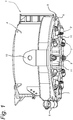
- the first embodiment of the clamp system as shown in figure 1 consists of the wedge type clamp which has generally been denoted by reference numeral 1, as well as the series 2 of gripping devices 3.
- the wedge type clamp 1 has an annular frame 4 which consists of two frame halves 5, 6 which are connected to each other through the hinge 7 and an actuator means 8 at one end. By energizing the actuator 8, the frame halves 5, 6 can be swung around the hinge 7 between an open position and the closed as shown. In the open position, the frame halves can be located around an object which upon closure of the frame halves 5, 6 is then be accommodated within the internal space 9 of the frame 4.
- the clamp system can be lifted by means of the lugs 10, onto which hoisting cables of a crane and the like are to be mounted.
- wedge assemblies 11 Around the internal space 9 of the frame, several wedge assemblies 11 have been spaced. These wedge assemblies are shown in radial section in figure 6 and 7 , and consist in a known way of wedge parts 12, 13 which are slideable along each other according to the slanting surfaces 14.
- the inner wedge part 13 has a friction surface 15 which engages the external surface 30 of the object 16, as shown in figures 3-7 .
- the initial frictional engagement between the wedge assembly 11 and the object can be obtained by means of the wedge assembly actuator 26.
- the wedge assemblies 11 In the upright position, the wedge assemblies 11 additionally clamp the object 16 securely in the internal space 9 of the wedge type clamp 1 under the influence of gravity, the clamp system itself being suspended from a crane and the like by hoisting cables 23 connected to the lugs 10 (only one of these being shown in figure 3 ).
- the series 2 of gripping devices 3 have been mounted on one axial end of the frame 4.
- These gripping devices 3 consist each of a piston/cylinder device 17 and the mounting plate 21.
- the housing 18 thereof is connected to the mounting plate 21 through the pivot 22, the pivot axis of which runs transverse with respect to the longitudinal axis of the piston/cylinder device 17.
- the piston 19 has a gripping surface 20 at its free end.
- the gripping devices 3 are energized in such a way that the gripping surfaces 20 thereof are pressed onto the object. Thereby, a stable position of the object 16 with respect to the clamp system 1 is obtained.
- the spring members 24 are holding the piston/cylinder devices 3 in the clamping position, at right angles to the axis of the frame 4.
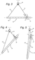
- Figures 3-5 show a particular lifting operation in which the clamp assembly may be used in a particular beneficial way.
- the object 11 has a lying or horizontal position. Near one of its ends, the clamp system 27 is positioned, a first hoisting cable 23 extending between the clamp system 27 and a double hoisting block 28 suspended from a crane (not shown). Furthermore, a second hoisting cable 29 extends between this double hoisting block 28 and the object 11, near the other end thereof.
- the force F as exerted by the first hoisting cable 23 on the clamp system 27 has a component F 1 which is oriented according to the axis of the clamp system 27, and counter to the direction in which the wedge assemblies thereof would be activated.
- the clamping action exerted by the wedge assemblies on the object appears to be insufficient to stabilize the clamp system 27 with respect to the object 11.
- by energizing the gripping devices 3 as described before such stable position of the clamp system 27 can still be obtained.
- the force component F 1 causes the piston/cylinder devices 17 to be pressed firmly onto the corresponding stop faces 25, the stability of the clamp system 27 with respect to the object is furthermore ascertained.
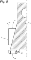
- the embodiment of the clamp system described before is fit for accommodating an object within the internal space 9 thereof.
- the clamp system may be carried out for introduction in the hollow space of a hollow object, as shown in figure 8 .
- both the wedge assemblies 11 and the gripping devices engage the inner surface 31 of the object 16.
- the way of handling this clamp system and object is however similar to the clamp system described before.
Landscapes
- Engineering & Computer Science (AREA)
- Mechanical Engineering (AREA)
- General Engineering & Computer Science (AREA)
- Civil Engineering (AREA)
- Structural Engineering (AREA)
- Load-Engaging Elements For Cranes (AREA)
- Manipulator (AREA)
- Placing Or Removing Of Piles Or Sheet Piles, Or Accessories Thereof (AREA)
- Earth Drilling (AREA)
- Clamps And Clips (AREA)
Claims (19)
- Einspannsystem für ein schmales Objekt (16), wie beispielsweise einen Pfahl oder ein Rohr und dergleichen, wobei das Einspannsystem eine Umfassung (4) umfasst, die eine Längsachse bildet, das Objekt und die Umfassung (4) so umeinander herum angeordnet werden, dass die Längsachse der Umfassung (4) im Allgemeinen parallel zu der Längsachse des Objektes (16) ist, sowie Einspanneinrichtungen (2), mit denen das Objekt (16) in Bezug auf die Umfassung (4) eingespannt wird, dadurch gekennzeichnet, dass die Einspanneinrichtungen umfassen:wenigstens eine Klemmvorrichtung (3), die mit der Umfassung (4) um eine Drehachse herum drehbar verbunden ist, die in Bezug auf die Längsachse der Umfassung (4) quer ausgerichtet ist, wobei die Klemmvorrichtung (3) einen Klemm-Zustand, in dem das Objekt (16) in Bezug auf die Umfassung (4) eingespannt ist, sowie einen Ruhe-Zustand hat, undwenigstens einen Anschlag (25), der eine Endposition der Klemmvorrichtung (3) bildet, wobei die Klemmvorrichtung (3), wenn sie sich in dem Klemm-Zustand befindet und die Endposition einnimmt, verhindert, dass das Objekt (16) in Bezug auf die Umfassung (4) in einer ersten axialen Richtung entlang der Längsachse der Umfassung (4) verschoben wird, wobei in der ersten axialen Richtung die Klemmvorrichtung (3) an den Anschlag (25) gepresst gehalten wird und die Klemmvorrichtung (3) Verschiebung des Objektes (16) in Bezug auf die Umfassung in einer zweiten axialen Richtung entgegengesetzt zu der ersten axialen Richtung zulässt.
- Einspannsystem nach Anspruch 1, wobei die Klemmvorrichtung (3) über ein entsprechendes Drehgelenk (22) an der Umfassung (4) angebracht ist und die Klemmvorrichtung (3) zwischen einer aktiven Position, die radial in Bezug auf die Längsachse der Umfassung (4) ausgerichtet ist, und einer inaktiven Position verschoben werden kann, die in Bezug auf die radial ausgerichtete aktive Position geneigt ist.
- Einspannsystem nach Anspruch 2, wobei sich der Anschlag (25) an der Umfassung (4) und/oder einem Träger oder einer Halterung (21) befindet.
- Einspannsystem nach Anspruch 3, wobei die Klemmvorrichtung (3) beispielsweise durch elastische Vorspannung auf den Anschlag (25) zu gespannt wird.
- Einspannsystem nach einem der vorangehenden Ansprüche zur Einführung in ein hohles Objekt (16), wobei die Klemmvorrichtung (3) so ausgeführt ist, dass die Innenfläche des hohlen Objektes (16) festgeklemmt wird.
- Einspannsystem nach einem der Ansprüche 1-4, wobei die Umfassung (4) einen Kanal (9) zum Aufnehmen des Objektes (16) begrenzt und die Klemmvorrichtung so ausgeführt ist, dass die Außenfläche des Objektes festgeklemmt wird.
- Einspannsystem nach Anspruch 6, wobei die Umfassung (4) Umfassungs-Hälften (5, 6) umfasst, die über ein Gelenk (7) miteinander verbunden sind, dessen Gelenkachse im Allgemeinen parallel zu der Längsachse der Umfassung (4) ist, und die Umfassungs-Hälften (5, 6) zwischen einer aktiven Position, in der sie um das Objekt herum zusammengeklappt sind, und einer offenen Position verstellt werden können, in der die Umfassung (4) an dem Objekt (16) positioniert werden kann.
- Einspannsystem nach Anspruch 7, wobei Verschlusseinrichtungen (8) an den Umfassungs-Hälften (5, 6) vorhanden sind, mit denen die Umfassungs-Hälften jeweils aneinandergepresst gehalten werden, um die Umfassungs-Hälften freizugeben.
- Einspannsystem nach einem der vorangehenden Ansprüche, die eine Keil-Einspannvorrichtung (1) umfasst, die Keilanordnungen (11) aufweist, die mit der Umfassung verbunden sind, um Reibeingriff mit dem Objekt aufgrund einer relativen Verschiebung der Keil-Einspannvorrichtung in Bezug auf das Objekt auf der Längsachse zu bewirken, wobei die Klemmvorrichtung in Bezug auf die Keilanordnungen so angeordnet ist, dass bei der relativen Verschiebung des Objektes und der Keil-Einspannvorrichtung (1) die Klemmvorrichtung (3) von dem Klemm-Zustand, in dem das Objekt (11) mit den Klemmvorrichtungen in Bezug auf die Umfassung (4) gehalten wird, in den Ruhe-Zustand versetzt wird und der Reibeingriff zwischen den Keilanordnungen (11) und dem Objekt (16) hergestellt wird.
- Einspannsystem nach Anspruch 9, wenn abhängig von Anspruch 5, wobei die Keilanordnungen (11) und eine Klemmvorrichtung (3) in Bezug auf die Umfassung (4) nach außen ausgerichtet sind, um mit der Innenfläche des hohlen Objektes (16) in Eingriff zu kommen.
- Einspannsystem nach Anspruch 9, wenn abhängig von Anspruch 6, wobei die Keilanordnungen (11) und die Klemmvorrichtung (3) in Bezug auf die Umfassung (4) nach innen ausgerichtet sind, um mit der Außenfläche (3) des Objektes (16) in Eingriff zu kommen.
- Einspannsystem nach einem der Ansprüche 9-10, wobei die Klemmvorrichtung (3) in axialer Richtung in einem Abstand zu den Keilanordnungen (11) positioniert ist.
- Einspannsystem nach einem der Ansprüche 9-12, wobei die Klemmvorrichtung (3) in der Richtung relativer Verschiebung des Objektes in Bezug auf die Umfassung (4), die Reibeingriff zwischen den Keilanordnungen und der Umfassung (4) bewirkt, aus der radialen Position heraus geschwenkt werden kann.
- Einspannsystem nach einem der Ansprüche 9-13, wobei die Umfassung (4) einander gegenüberliegende axiale Enden hat und die Klemmvorrichtung (3) an dem Ende positioniert ist, das in die Einspann-Richtung der Keilanordnungen (11) gewandt ist.
- Einspannsystem nach einem der vorangehenden Ansprüche, wobei eine Vielzahl von Klemmvorrichtungen (3) vorhanden ist und die Klemmvorrichtungen um die Längsachse der Umfassung (4) herum beabstandet und quer in Bezug zu ihr ausgerichtet sind.
- Verfahren zum Anheben eines hohlen schmalen Objektes (16) mit dem Einspannsystem nach Anspruch 10 oder einem der Ansprüche 12-15, wenn abhängig von Anspruch 10, das die folgenden Schritte umfasst:Einführen der Umfassung (4) in das liegende Objekt (16),Aktivieren der Keilanordnungen (11), so dass sie mit der Innenfläche des liegenden Objektes (16) in Eingriff kommen,Aktivieren einer oder mehrerer Klemmvorrichtung/en (3), so dass sie die Innenfläche des liegenden Objektes (16) festklemmt/festklemmen,Anheben des mit der/den Klemmvorrichtung/en festgeklemmten Objektes und Überführen des Objektes in Richtung einer aufrechtstehenden Position,Verschieben des Objektes in Bezug auf die Umfassung (4), um Reibeingriff zwischen den Keilanordnungen (11) derselben und dem Objekt (16) zu erzeugen oder zu verstärken, während des Vorgangs des Überführens des Objektes an die aufrechtstehende Position,Überführen der Klemmvorrichtung/en von dem Klemm-Zustand in den Ruhe-Zustand während des Vorgangs des Überführens des Objektes an die aufrechtstehende Position.
- Verfahren zum Anheben eines schmalen Objektes (16) mit dem Einspannsystem nach Anspruch 11 oder einem der Ansprüche 12-15, wenn abhängig von Anspruch 11, das die folgenden Schritte umfasst:Passen der Umfassung (4) um ein liegendes Objekt (16) herum,Aktivieren der Keilanordnungen (11), so dass sie mit der Außenfläche des liegenden Objektes (16) in Eingriff kommen,Aktivieren einer oder mehrerer Klemmvorrichtung/en (3), so dass sie die Außenfläche (30) des liegenden Objektes (16) festklemmen,Anheben des mit der/den Klemmvorrichtung/en festgeklemmten Objektes und Überführen des Objektes in Richtung einer aufrechtstehenden Position,Verschieben des Objektes in Bezug auf die Umfassung (4), um Reibeingriff zwischen den Keilanordnungen (11) derselben und dem Objekt (16) zu erzeugen oder zu verstärken, während des Vorgangs des Überführens des Objektes an die aufrechtstehende Position,Überführen der Klemmvorrichtung/en von dem Klemm-Zustand in den Ruhe-Zustand während des Vorgangs des Überführens des Objektes an die aufrechtstehende Position.
- Verfahren nach Anspruch 16 oder 17, das den folgenden Schritt umfasst:Überführen einer oder mehrerer Klemmvorrichtung/en (3) von dem Klemm-Zustand in den Ruhe-Zustand während des Vorgangs des Überführens des Objektes (16) an die aufrechtstehende Position, indem bewirkt wird, dass sich die Klemmvorrichtung/en um die jeweils tangential ausgerichtete Drehachse derselben herum dreht/drehen.
- Verfahren nach Anspruch 16, 17 oder 18, das die folgenden Schritte umfasst:Verschieben des Objektes (16) in Bezug auf die Einspannsystem unter dem Einfluss der Schwerkraft aufgrund von Überführen des Objektes auf die aufrechtstehende Position zu,Schwenken der Klemmvorrichtung/en (3) von der Klemm-Position an die Ruhe-Position während des Schrittes des Verschiebens des Objektes in Bezug auf die Keil-Einspannvorrichtung (1).
Applications Claiming Priority (2)
| Application Number | Priority Date | Filing Date | Title |
|---|---|---|---|
| NL2010299A NL2010299C2 (en) | 2013-02-14 | 2013-02-14 | Clamp system, gripping device therefore and method of using the clamp system. |
| PCT/NL2014/050088 WO2014126465A1 (en) | 2013-02-14 | 2014-02-13 | Clamp system, gripping device therefore and method of using the clamp system |
Publications (3)
| Publication Number | Publication Date |
|---|---|
| EP2956397A1 EP2956397A1 (de) | 2015-12-23 |
| EP2956397B1 true EP2956397B1 (de) | 2018-01-03 |
| EP2956397B8 EP2956397B8 (de) | 2018-06-27 |
Family
ID=48050215
Family Applications (1)
| Application Number | Title | Priority Date | Filing Date |
|---|---|---|---|
| EP14706961.1A Active EP2956397B8 (de) | 2013-02-14 | 2014-02-13 | Klemmsystem und verfahren zur verwendung des klemmsystems |
Country Status (12)
| Country | Link |
|---|---|
| US (1) | US9670036B2 (de) |
| EP (1) | EP2956397B8 (de) |
| JP (1) | JP6351121B2 (de) |
| KR (1) | KR102195790B1 (de) |
| CN (1) | CN105121325B (de) |
| AU (1) | AU2014216796B2 (de) |
| BR (1) | BR112015019501B1 (de) |
| CA (1) | CA2901069C (de) |
| DK (1) | DK2956397T3 (de) |
| NL (1) | NL2010299C2 (de) |
| SG (1) | SG11201506386QA (de) |
| WO (1) | WO2014126465A1 (de) |
Families Citing this family (17)
| Publication number | Priority date | Publication date | Assignee | Title |
|---|---|---|---|---|
| GB201418635D0 (en) * | 2014-10-20 | 2014-12-03 | Credeco Contractors Ltd | Engaging apparatus |
| JP6472992B2 (ja) * | 2014-12-11 | 2019-02-20 | 大同マシナリー株式会社 | 管継手締付機 |
| CN104846799B (zh) * | 2015-05-20 | 2016-08-17 | 中石化胜利油建工程有限公司 | 一种增力式夹桩器 |
| US10068438B2 (en) | 2015-08-11 | 2018-09-04 | Emadeddin Zahri Muntasser | L-style marking clamp |
| CN106013027B (zh) * | 2016-05-19 | 2018-01-26 | 武汉船用机械有限责任公司 | 一种适用于升降平台的固桩系统 |
| CN105855774B (zh) * | 2016-06-02 | 2018-03-02 | 昆山江鸿精密电子有限公司 | 一种多角度焊接机构 |
| CN106144903B (zh) * | 2016-06-24 | 2017-08-25 | 中国十七冶集团有限公司 | 一种建筑风管防变形吊装装置及吊装方法 |
| CN108002217B (zh) * | 2017-12-06 | 2019-06-04 | 安徽江淮汽车集团股份有限公司 | 一种吊具 |
| CN108360487B (zh) * | 2018-05-03 | 2023-08-29 | 中船黄埔文冲船舶有限公司 | 八角型桩腿防转装置 |
| CN110863785A (zh) * | 2018-08-27 | 2020-03-06 | 中国石油天然气股份有限公司 | 钻具固定装置 |
| JP7234604B2 (ja) * | 2018-11-27 | 2023-03-08 | 京セラドキュメントソリューションズ株式会社 | 把持機構及び組み立て装置 |
| CN109632347A (zh) * | 2018-12-07 | 2019-04-16 | 宁波拓普集团股份有限公司 | 一种汽车悬置的在线检测工装 |
| NL2023436B1 (en) * | 2019-07-04 | 2021-02-02 | Ihc Holland Ie Bv | A lifting device and a method of lifting a tubular pile |
| CN110436342B (zh) * | 2019-07-24 | 2022-11-04 | 蜂巢能源科技有限公司 | 吊装装置及封装电池包吊装工具 |
| CN110422618B (zh) * | 2019-07-31 | 2024-04-16 | 郑州新生印务有限公司 | 一种包装箱码垛机械手 |
| CN111674943B (zh) * | 2020-05-19 | 2021-10-08 | 杭州德创能源设备有限公司 | 码垛机 |
| CN113400338B (zh) * | 2021-08-18 | 2021-11-09 | 雄俊金属制品(南通)有限公司 | 一种安全稳固型金属机械手 |
Family Cites Families (36)
| Publication number | Priority date | Publication date | Assignee | Title |
|---|---|---|---|---|
| US1693478A (en) * | 1925-08-21 | 1928-11-27 | George Krell | Pipe clamp |
| US1721024A (en) * | 1927-01-14 | 1929-07-16 | Krell | Elevator or spider |
| US1797494A (en) * | 1929-04-20 | 1931-03-24 | Grant John | Slip-ring elevator |
| GB1015381A (en) * | 1963-04-10 | 1965-12-31 | Brown Lenox & Company Ltd | Lifting device for handling convection spacer discs and similar articles |
| US3268968A (en) * | 1964-11-19 | 1966-08-30 | Joy Mfg Co | Slip handle |
| US3720435A (en) * | 1970-02-02 | 1973-03-13 | H Leyn | Spud clamping device |
| JPS5135089Y2 (de) * | 1972-05-25 | 1976-08-30 | ||
| JPS5489775U (de) * | 1977-12-09 | 1979-06-25 | ||
| JPS54178374U (de) * | 1978-06-07 | 1979-12-17 | ||
| US4354706A (en) * | 1980-06-02 | 1982-10-19 | Bilco Tools, Inc. | Dual string elevators |
| US4940118A (en) | 1988-10-31 | 1990-07-10 | Otis Engineering Corporation | Slip assembly |
| DE4107931C1 (de) * | 1991-03-08 | 1992-02-27 | Mannesmann Ag, 4000 Duesseldorf, De | |
| JP2571508B2 (ja) | 1992-12-28 | 1997-01-16 | 株式会社技研製作所 | 杭の保持体 |
| JPH0941866A (ja) | 1995-07-31 | 1997-02-10 | Y B M Hanbai Kk | ロッドホルダー |
| DE29724354U1 (de) * | 1997-05-23 | 2000-12-21 | Preussag Spezialtiefbau GmbH, 30625 Hannover | Vorrichtung zum Ziehen einer Rohrtour |
| CN2434290Y (zh) * | 2000-04-20 | 2001-06-13 | 上海三菱电梯有限公司 | 起吊轴类件的自锁式吊具 |
| US6915868B1 (en) * | 2000-11-28 | 2005-07-12 | Frank's Casing Crew And Rental Tools, Inc. | Elevator apparatus and method for running well bore tubing |
| NL1028656C1 (nl) * | 2005-03-30 | 2006-10-03 | Inter Product Bv | Kleminrichting voor het vastklemmen van plaatmateriaal. |
| US8141923B2 (en) * | 2007-01-19 | 2012-03-27 | Frank's Casing Crew And Rental Tools, Inc. | Single joint elevator having deployable jaws |
| US7992634B2 (en) * | 2007-08-28 | 2011-08-09 | Frank's Casing Crew And Rental Tools, Inc. | Adjustable pipe guide for use with an elevator and/or a spider |
| US7681649B2 (en) * | 2007-11-08 | 2010-03-23 | Tesco Corporation | Power slips |
| WO2009137414A1 (en) * | 2008-05-03 | 2009-11-12 | Frank's International, Inc. | Tubular grip interlock system |
| US9115547B2 (en) | 2009-06-22 | 2015-08-25 | Frank's International, Llc | Large diameter tubular lifting apparatuses and methods |
| DE112010004523A5 (de) | 2009-11-23 | 2012-10-25 | Blohm + Voss Repair Gmbh | Vorrichtung zur handhabung von rohren |
| US8434969B2 (en) * | 2010-04-02 | 2013-05-07 | American Piledriving Equipment, Inc. | Internal pipe clamp |
| NL2005542C2 (en) | 2010-10-18 | 2012-04-19 | Ihc Handling Systems Vof | Clamping device. |
| GB2486200A (en) | 2010-12-06 | 2012-06-13 | Balltec Ltd | Gripping device for handling tubular members |
| NL2005967C2 (en) * | 2011-01-07 | 2012-07-10 | Ihc Handling Systems Vof | Clamping device. |
| BR112013033612B1 (pt) * | 2011-05-01 | 2019-03-06 | Frank's International, Llc | Elevador de campo petrolífero, método e aparelho para acoplar um segmento tubular |
| CA2834857C (en) | 2011-05-01 | 2016-04-26 | Frank's Casing Crew And Rental Tools, Inc. | Single upset landing string running system |
| CN202175503U (zh) * | 2011-07-27 | 2012-03-28 | 湖南华洋铜业股份有限公司 | 一种管道吊具 |
| EP2770112B1 (de) * | 2013-02-20 | 2016-02-17 | Overdick GmbH & co. KG | Hebeeinrichtung für Offshore-Plattformen |
| US9452535B2 (en) * | 2013-05-31 | 2016-09-27 | National Oilwell Varco, L.P. | Self-aligning pipe gripping assembly and method of making and using the same |
| US9605497B2 (en) * | 2014-02-27 | 2017-03-28 | Frank's International, Llc | Drill pipe and casing elevator |
| US9206655B2 (en) * | 2014-03-14 | 2015-12-08 | David L. Sipos | 360 degree shoulder clamp elevator and method of use |
| US10036215B2 (en) * | 2014-03-28 | 2018-07-31 | Weatherford Technology Holdings, Llc | Swivel elevator |
-
2013
- 2013-02-14 NL NL2010299A patent/NL2010299C2/en not_active IP Right Cessation
-
2014
- 2014-02-13 CA CA2901069A patent/CA2901069C/en active Active
- 2014-02-13 DK DK14706961.1T patent/DK2956397T3/en active
- 2014-02-13 CN CN201480021066.7A patent/CN105121325B/zh active Active
- 2014-02-13 US US14/767,684 patent/US9670036B2/en active Active
- 2014-02-13 EP EP14706961.1A patent/EP2956397B8/de active Active
- 2014-02-13 WO PCT/NL2014/050088 patent/WO2014126465A1/en not_active Ceased
- 2014-02-13 BR BR112015019501-6A patent/BR112015019501B1/pt active IP Right Grant
- 2014-02-13 AU AU2014216796A patent/AU2014216796B2/en active Active
- 2014-02-13 JP JP2015557966A patent/JP6351121B2/ja active Active
- 2014-02-13 KR KR1020157025063A patent/KR102195790B1/ko active Active
- 2014-02-13 SG SG11201506386QA patent/SG11201506386QA/en unknown
Non-Patent Citations (1)
| Title |
|---|
| None * |
Also Published As
| Publication number | Publication date |
|---|---|
| BR112015019501A2 (pt) | 2017-07-18 |
| SG11201506386QA (en) | 2015-09-29 |
| CA2901069C (en) | 2020-07-14 |
| EP2956397B8 (de) | 2018-06-27 |
| WO2014126465A1 (en) | 2014-08-21 |
| JP6351121B2 (ja) | 2018-07-04 |
| AU2014216796B2 (en) | 2018-03-15 |
| CN105121325B (zh) | 2017-08-25 |
| CN105121325A (zh) | 2015-12-02 |
| KR102195790B1 (ko) | 2020-12-29 |
| AU2014216796A1 (en) | 2015-09-10 |
| KR20150119257A (ko) | 2015-10-23 |
| JP2016515987A (ja) | 2016-06-02 |
| BR112015019501B1 (pt) | 2021-05-18 |
| NL2010299C2 (en) | 2014-08-18 |
| EP2956397A1 (de) | 2015-12-23 |
| US20150368073A1 (en) | 2015-12-24 |
| DK2956397T3 (en) | 2018-02-12 |
| US9670036B2 (en) | 2017-06-06 |
| CA2901069A1 (en) | 2014-08-21 |
Similar Documents
| Publication | Publication Date | Title |
|---|---|---|
| EP2956397B1 (de) | Klemmsystem und verfahren zur verwendung des klemmsystems | |
| EP3297945B1 (de) | Flanschhebewerkzeug | |
| US4235469A (en) | Pipe handling apparatus | |
| EP2661408B1 (de) | Spannvorrichtung | |
| EP3101218B1 (de) | Vorrichtung zur unterstützung eines rohrförmigen elements | |
| US8919429B2 (en) | Single upset landing string running system | |
| US20050092500A1 (en) | Large diameter flush-joint pipe handling system | |
| EP3230553B1 (de) | Spannringanordnung | |
| US10352112B2 (en) | Device and method for suspending loads from a bail of an elevator of a drilling rig, and corresponding drilling rig assembly | |
| US20240318746A1 (en) | Clamp for holding a flexible slender structure | |
| EP2808481A1 (de) | Verfahren und Anlage zur Montage oder Demontage eines Rohrstrangs und Kopplungselement zur Verwendung darin | |
| JPH07215660A (ja) | 異径内面つき物品の吊上治具 | |
| EP2705215B1 (de) | Aufnahmesystem mit einzelnen aufnahmestangen | |
| KR102726445B1 (ko) | 슬랙 방지 릴리즈 후크 | |
| CN105692427A (zh) | 一种铝棒转运装置用吊轴机构 | |
| MXPA05005002A (es) | Sistema de manejo de tuberia de. junta lisa de diametro grande. | |
| EP0670193A2 (de) | Spannvorrichtung mit ausdehnbarem Spanndorn | |
| NO20171295A1 (en) | Device and method for suspending loads from a bail of an elevator of a drilling rig, and corresponding drilling rig assembly | |
| WO2015080593A2 (en) | Safety release device |
Legal Events
| Date | Code | Title | Description |
|---|---|---|---|
| PUAI | Public reference made under article 153(3) epc to a published international application that has entered the european phase |
Free format text: ORIGINAL CODE: 0009012 |
|
| 17P | Request for examination filed |
Effective date: 20150813 |
|
| AK | Designated contracting states |
Kind code of ref document: A1 Designated state(s): AL AT BE BG CH CY CZ DE DK EE ES FI FR GB GR HR HU IE IS IT LI LT LU LV MC MK MT NL NO PL PT RO RS SE SI SK SM TR |
|
| AX | Request for extension of the european patent |
Extension state: BA ME |
|
| DAX | Request for extension of the european patent (deleted) | ||
| GRAP | Despatch of communication of intention to grant a patent |
Free format text: ORIGINAL CODE: EPIDOSNIGR1 |
|
| RIC1 | Information provided on ipc code assigned before grant |
Ipc: E02B 17/06 20060101ALI20170106BHEP Ipc: E02B 17/08 20060101ALI20170106BHEP Ipc: B66C 1/44 20060101AFI20170106BHEP |
|
| INTG | Intention to grant announced |
Effective date: 20170202 |
|
| RIN1 | Information on inventor provided before grant (corrected) |
Inventor name: BELDER, CORNELIS Inventor name: MULDERIJ, KLAAS-JAN |
|
| GRAJ | Information related to disapproval of communication of intention to grant by the applicant or resumption of examination proceedings by the epo deleted |
Free format text: ORIGINAL CODE: EPIDOSDIGR1 |
|
| GRAP | Despatch of communication of intention to grant a patent |
Free format text: ORIGINAL CODE: EPIDOSNIGR1 |
|
| INTC | Intention to grant announced (deleted) | ||
| INTG | Intention to grant announced |
Effective date: 20170721 |
|
| GRAS | Grant fee paid |
Free format text: ORIGINAL CODE: EPIDOSNIGR3 |
|
| GRAA | (expected) grant |
Free format text: ORIGINAL CODE: 0009210 |
|
| AK | Designated contracting states |
Kind code of ref document: B1 Designated state(s): AL AT BE BG CH CY CZ DE DK EE ES FI FR GB GR HR HU IE IS IT LI LT LU LV MC MK MT NL NO PL PT RO RS SE SI SK SM TR |
|
| REG | Reference to a national code |
Ref country code: GB Ref legal event code: FG4D |
|
| REG | Reference to a national code |
Ref country code: CH Ref legal event code: EP Ref country code: AT Ref legal event code: REF Ref document number: 960050 Country of ref document: AT Kind code of ref document: T Effective date: 20180115 |
|
| REG | Reference to a national code |
Ref country code: IE Ref legal event code: FG4D |
|
| REG | Reference to a national code |
Ref country code: DK Ref legal event code: T3 Effective date: 20180207 |
|
| REG | Reference to a national code |
Ref country code: DE Ref legal event code: R096 Ref document number: 602014019356 Country of ref document: DE |
|
| REG | Reference to a national code |
Ref country code: FR Ref legal event code: PLFP Year of fee payment: 5 |
|
| REG | Reference to a national code |
Ref country code: SE Ref legal event code: TRGR |
|
| REG | Reference to a national code |
Ref country code: NL Ref legal event code: FP |
|
| REG | Reference to a national code |
Ref country code: DE Ref legal event code: R081 Ref document number: 602014019356 Country of ref document: DE Owner name: IHC HOLLAND IE B.V., NL Free format text: FORMER OWNER: IHC HOLLAND IE N.V., SLIEDRECHT, NL |
|
| RAP2 | Party data changed (patent owner data changed or rights of a patent transferred) |
Owner name: IHC HOLLAND IE B.V. |
|
| REG | Reference to a national code |
Ref country code: LT Ref legal event code: MG4D |
|
| PGFP | Annual fee paid to national office [announced via postgrant information from national office to epo] |
Ref country code: IE Payment date: 20180226 Year of fee payment: 5 |
|
| REG | Reference to a national code |
Ref country code: AT Ref legal event code: MK05 Ref document number: 960050 Country of ref document: AT Kind code of ref document: T Effective date: 20180103 |
|
| PG25 | Lapsed in a contracting state [announced via postgrant information from national office to epo] |
Ref country code: FI Free format text: LAPSE BECAUSE OF FAILURE TO SUBMIT A TRANSLATION OF THE DESCRIPTION OR TO PAY THE FEE WITHIN THE PRESCRIBED TIME-LIMIT Effective date: 20180103 Ref country code: HR Free format text: LAPSE BECAUSE OF FAILURE TO SUBMIT A TRANSLATION OF THE DESCRIPTION OR TO PAY THE FEE WITHIN THE PRESCRIBED TIME-LIMIT Effective date: 20180103 Ref country code: CY Free format text: LAPSE BECAUSE OF FAILURE TO SUBMIT A TRANSLATION OF THE DESCRIPTION OR TO PAY THE FEE WITHIN THE PRESCRIBED TIME-LIMIT Effective date: 20180103 Ref country code: NO Free format text: LAPSE BECAUSE OF FAILURE TO SUBMIT A TRANSLATION OF THE DESCRIPTION OR TO PAY THE FEE WITHIN THE PRESCRIBED TIME-LIMIT Effective date: 20180403 Ref country code: LT Free format text: LAPSE BECAUSE OF FAILURE TO SUBMIT A TRANSLATION OF THE DESCRIPTION OR TO PAY THE FEE WITHIN THE PRESCRIBED TIME-LIMIT Effective date: 20180103 Ref country code: ES Free format text: LAPSE BECAUSE OF FAILURE TO SUBMIT A TRANSLATION OF THE DESCRIPTION OR TO PAY THE FEE WITHIN THE PRESCRIBED TIME-LIMIT Effective date: 20180103 |
|
| REG | Reference to a national code |
Ref country code: BE Ref legal event code: PD Owner name: IHC HOLLAND IE B.V.; NL Free format text: DETAILS ASSIGNMENT: CHANGE OF OWNER(S), CHANGEMENT DE FORME JURIDIQUE; FORMER OWNER NAME: IHC HOLLAND IE N.V. Effective date: 20180529 |
|
| PG25 | Lapsed in a contracting state [announced via postgrant information from national office to epo] |
Ref country code: IS Free format text: LAPSE BECAUSE OF FAILURE TO SUBMIT A TRANSLATION OF THE DESCRIPTION OR TO PAY THE FEE WITHIN THE PRESCRIBED TIME-LIMIT Effective date: 20180503 Ref country code: AT Free format text: LAPSE BECAUSE OF FAILURE TO SUBMIT A TRANSLATION OF THE DESCRIPTION OR TO PAY THE FEE WITHIN THE PRESCRIBED TIME-LIMIT Effective date: 20180103 Ref country code: RS Free format text: LAPSE BECAUSE OF FAILURE TO SUBMIT A TRANSLATION OF THE DESCRIPTION OR TO PAY THE FEE WITHIN THE PRESCRIBED TIME-LIMIT Effective date: 20180103 Ref country code: BG Free format text: LAPSE BECAUSE OF FAILURE TO SUBMIT A TRANSLATION OF THE DESCRIPTION OR TO PAY THE FEE WITHIN THE PRESCRIBED TIME-LIMIT Effective date: 20180403 Ref country code: PL Free format text: LAPSE BECAUSE OF FAILURE TO SUBMIT A TRANSLATION OF THE DESCRIPTION OR TO PAY THE FEE WITHIN THE PRESCRIBED TIME-LIMIT Effective date: 20180103 Ref country code: GR Free format text: LAPSE BECAUSE OF FAILURE TO SUBMIT A TRANSLATION OF THE DESCRIPTION OR TO PAY THE FEE WITHIN THE PRESCRIBED TIME-LIMIT Effective date: 20180404 Ref country code: LV Free format text: LAPSE BECAUSE OF FAILURE TO SUBMIT A TRANSLATION OF THE DESCRIPTION OR TO PAY THE FEE WITHIN THE PRESCRIBED TIME-LIMIT Effective date: 20180103 |
|
| REG | Reference to a national code |
Ref country code: CH Ref legal event code: PL |
|
| REG | Reference to a national code |
Ref country code: DE Ref legal event code: R097 Ref document number: 602014019356 Country of ref document: DE |
|
| PG25 | Lapsed in a contracting state [announced via postgrant information from national office to epo] |
Ref country code: RO Free format text: LAPSE BECAUSE OF FAILURE TO SUBMIT A TRANSLATION OF THE DESCRIPTION OR TO PAY THE FEE WITHIN THE PRESCRIBED TIME-LIMIT Effective date: 20180103 Ref country code: EE Free format text: LAPSE BECAUSE OF FAILURE TO SUBMIT A TRANSLATION OF THE DESCRIPTION OR TO PAY THE FEE WITHIN THE PRESCRIBED TIME-LIMIT Effective date: 20180103 Ref country code: AL Free format text: LAPSE BECAUSE OF FAILURE TO SUBMIT A TRANSLATION OF THE DESCRIPTION OR TO PAY THE FEE WITHIN THE PRESCRIBED TIME-LIMIT Effective date: 20180103 Ref country code: MC Free format text: LAPSE BECAUSE OF FAILURE TO SUBMIT A TRANSLATION OF THE DESCRIPTION OR TO PAY THE FEE WITHIN THE PRESCRIBED TIME-LIMIT Effective date: 20180103 |
|
| PLBE | No opposition filed within time limit |
Free format text: ORIGINAL CODE: 0009261 |
|
| STAA | Information on the status of an ep patent application or granted ep patent |
Free format text: STATUS: NO OPPOSITION FILED WITHIN TIME LIMIT |
|
| PG25 | Lapsed in a contracting state [announced via postgrant information from national office to epo] |
Ref country code: SK Free format text: LAPSE BECAUSE OF FAILURE TO SUBMIT A TRANSLATION OF THE DESCRIPTION OR TO PAY THE FEE WITHIN THE PRESCRIBED TIME-LIMIT Effective date: 20180103 Ref country code: LI Free format text: LAPSE BECAUSE OF NON-PAYMENT OF DUE FEES Effective date: 20180228 Ref country code: LU Free format text: LAPSE BECAUSE OF NON-PAYMENT OF DUE FEES Effective date: 20180213 Ref country code: CH Free format text: LAPSE BECAUSE OF NON-PAYMENT OF DUE FEES Effective date: 20180228 Ref country code: SM Free format text: LAPSE BECAUSE OF FAILURE TO SUBMIT A TRANSLATION OF THE DESCRIPTION OR TO PAY THE FEE WITHIN THE PRESCRIBED TIME-LIMIT Effective date: 20180103 Ref country code: CZ Free format text: LAPSE BECAUSE OF FAILURE TO SUBMIT A TRANSLATION OF THE DESCRIPTION OR TO PAY THE FEE WITHIN THE PRESCRIBED TIME-LIMIT Effective date: 20180103 |
|
| 26N | No opposition filed |
Effective date: 20181005 |
|
| PG25 | Lapsed in a contracting state [announced via postgrant information from national office to epo] |
Ref country code: SI Free format text: LAPSE BECAUSE OF FAILURE TO SUBMIT A TRANSLATION OF THE DESCRIPTION OR TO PAY THE FEE WITHIN THE PRESCRIBED TIME-LIMIT Effective date: 20180103 |
|
| REG | Reference to a national code |
Ref country code: NL Ref legal event code: RC Free format text: DETAILS LICENCE OR PLEDGE: RIGHT OF PLEDGE, ESTABLISHED, 1E RANG Name of requester: ING BANK N.V. Effective date: 20190826 |
|
| REG | Reference to a national code |
Ref country code: NL Ref legal event code: RC Free format text: DETAILS LICENCE OR PLEDGE: RIGHT OF PLEDGE, ESTABLISHED, 2E PANDRECHT Name of requester: ING BANK N.V. Effective date: 20190903 |
|
| REG | Reference to a national code |
Ref country code: IE Ref legal event code: MM4A |
|
| PG25 | Lapsed in a contracting state [announced via postgrant information from national office to epo] |
Ref country code: MT Free format text: LAPSE BECAUSE OF NON-PAYMENT OF DUE FEES Effective date: 20180213 Ref country code: IE Free format text: LAPSE BECAUSE OF NON-PAYMENT OF DUE FEES Effective date: 20190213 |
|
| PG25 | Lapsed in a contracting state [announced via postgrant information from national office to epo] |
Ref country code: TR Free format text: LAPSE BECAUSE OF FAILURE TO SUBMIT A TRANSLATION OF THE DESCRIPTION OR TO PAY THE FEE WITHIN THE PRESCRIBED TIME-LIMIT Effective date: 20180103 |
|
| PG25 | Lapsed in a contracting state [announced via postgrant information from national office to epo] |
Ref country code: PT Free format text: LAPSE BECAUSE OF FAILURE TO SUBMIT A TRANSLATION OF THE DESCRIPTION OR TO PAY THE FEE WITHIN THE PRESCRIBED TIME-LIMIT Effective date: 20180103 |
|
| PG25 | Lapsed in a contracting state [announced via postgrant information from national office to epo] |
Ref country code: HU Free format text: LAPSE BECAUSE OF FAILURE TO SUBMIT A TRANSLATION OF THE DESCRIPTION OR TO PAY THE FEE WITHIN THE PRESCRIBED TIME-LIMIT; INVALID AB INITIO Effective date: 20140213 Ref country code: MK Free format text: LAPSE BECAUSE OF NON-PAYMENT OF DUE FEES Effective date: 20180103 |
|
| REG | Reference to a national code |
Ref country code: NL Ref legal event code: RC Free format text: DETAILS LICENCE OR PLEDGE: RIGHT OF PLEDGE, ESTABLISHED Name of requester: GLAS TRUST CORPORATION LIMITED Effective date: 20200623 |
|
| P01 | Opt-out of the competence of the unified patent court (upc) registered |
Effective date: 20230525 |
|
| REG | Reference to a national code |
Ref country code: NL Ref legal event code: PD Owner name: IHC IQIP HOLDING B.V.; NL Free format text: DETAILS ASSIGNMENT: CHANGE OF OWNER(S), ASSIGNMENT; FORMER OWNER NAME: IHC HOLLAND IE B.V. Effective date: 20230626 Ref country code: NL Ref legal event code: HC Owner name: IQIP HOLDING B.V.; NL Free format text: DETAILS ASSIGNMENT: CHANGE OF OWNER(S), CHANGE OF OWNER(S) NAME; FORMER OWNER NAME: IHC IQIP HOLDING B.V. Effective date: 20230626 Ref country code: GB Ref legal event code: 732E Free format text: REGISTERED BETWEEN 20230608 AND 20230614 |
|
| REG | Reference to a national code |
Ref country code: DE Ref legal event code: R081 Ref document number: 602014019356 Country of ref document: DE Owner name: IQIP HOLDING B.V., NL Free format text: FORMER OWNER: IHC IQIP HOLDING B.V., SLIEDRECHT, NL Ref country code: DE Ref legal event code: R081 Ref document number: 602014019356 Country of ref document: DE Owner name: IQIP HOLDING B.V., NL Free format text: FORMER OWNER: IHC HOLLAND IE B.V., SLIEDRECHT, NL |
|
| REG | Reference to a national code |
Ref country code: BE Ref legal event code: PD Owner name: IHC IQIP HOLDING B.V.; NL Free format text: DETAILS ASSIGNMENT: CHANGE OF OWNER(S), ASSIGNMENT; FORMER OWNER NAME: IHC HOLLAND IE B.V. Effective date: 20230711 Ref country code: BE Ref legal event code: HC Owner name: IQIP HOLDING B.V.; NL Free format text: DETAILS ASSIGNMENT: CHANGE OF OWNER(S), CHANGE OF OWNER(S) NAME; FORMER OWNER NAME: IHC IQIP HOLDING B.V. Effective date: 20230711 |
|
| PGFP | Annual fee paid to national office [announced via postgrant information from national office to epo] |
Ref country code: NL Payment date: 20250220 Year of fee payment: 12 |
|
| PGFP | Annual fee paid to national office [announced via postgrant information from national office to epo] |
Ref country code: DE Payment date: 20250218 Year of fee payment: 12 |
|
| PGFP | Annual fee paid to national office [announced via postgrant information from national office to epo] |
Ref country code: DK Payment date: 20250219 Year of fee payment: 12 |
|
| PGFP | Annual fee paid to national office [announced via postgrant information from national office to epo] |
Ref country code: SE Payment date: 20250219 Year of fee payment: 12 |
|
| PGFP | Annual fee paid to national office [announced via postgrant information from national office to epo] |
Ref country code: BE Payment date: 20250218 Year of fee payment: 12 |
|
| PGFP | Annual fee paid to national office [announced via postgrant information from national office to epo] |
Ref country code: FR Payment date: 20250219 Year of fee payment: 12 |
|
| PGFP | Annual fee paid to national office [announced via postgrant information from national office to epo] |
Ref country code: IT Payment date: 20250228 Year of fee payment: 12 Ref country code: GB Payment date: 20250220 Year of fee payment: 12 |