EP2808481A1 - Verfahren und Anlage zur Montage oder Demontage eines Rohrstrangs und Kopplungselement zur Verwendung darin - Google Patents
Verfahren und Anlage zur Montage oder Demontage eines Rohrstrangs und Kopplungselement zur Verwendung darin Download PDFInfo
- Publication number
- EP2808481A1 EP2808481A1 EP13195492.7A EP13195492A EP2808481A1 EP 2808481 A1 EP2808481 A1 EP 2808481A1 EP 13195492 A EP13195492 A EP 13195492A EP 2808481 A1 EP2808481 A1 EP 2808481A1
- Authority
- EP
- European Patent Office
- Prior art keywords
- pipe
- pipes
- hollow body
- coupling member
- optionally
- Prior art date
- Legal status (The legal status is an assumption and is not a legal conclusion. Google has not performed a legal analysis and makes no representation as to the accuracy of the status listed.)
- Withdrawn
Links
- 230000008878 coupling Effects 0.000 title claims abstract description 69
- 238000010168 coupling process Methods 0.000 title claims abstract description 69
- 238000005859 coupling reaction Methods 0.000 title claims abstract description 69
- 238000009434 installation Methods 0.000 title claims abstract description 35
- 238000000034 method Methods 0.000 title claims abstract description 28
- RZVAJINKPMORJF-UHFFFAOYSA-N Acetaminophen Chemical compound CC(=O)NC1=CC=C(O)C=C1 RZVAJINKPMORJF-UHFFFAOYSA-N 0.000 claims abstract description 4
- 238000006073 displacement reaction Methods 0.000 description 3
- 239000000463 material Substances 0.000 description 3
- 230000002093 peripheral effect Effects 0.000 description 3
- 238000003780 insertion Methods 0.000 description 2
- 230000037431 insertion Effects 0.000 description 2
- 238000007789 sealing Methods 0.000 description 2
- 238000012360 testing method Methods 0.000 description 2
- WJXQFVMTIGJBFX-UHFFFAOYSA-N 4-methoxytyramine Chemical compound COC1=CC=C(CCN)C=C1O WJXQFVMTIGJBFX-UHFFFAOYSA-N 0.000 description 1
- 241000191291 Abies alba Species 0.000 description 1
- 230000003213 activating effect Effects 0.000 description 1
- 238000010276 construction Methods 0.000 description 1
- 238000005259 measurement Methods 0.000 description 1
- 238000012986 modification Methods 0.000 description 1
- 230000004048 modification Effects 0.000 description 1
- 210000003739 neck Anatomy 0.000 description 1
- 229920003023 plastic Polymers 0.000 description 1
- 230000000717 retained effect Effects 0.000 description 1
- 239000000725 suspension Substances 0.000 description 1
- 229920000785 ultra high molecular weight polyethylene Polymers 0.000 description 1
- 230000003313 weakening effect Effects 0.000 description 1
Images


Classifications
-
- E—FIXED CONSTRUCTIONS
- E21—EARTH OR ROCK DRILLING; MINING
- E21B—EARTH OR ROCK DRILLING; OBTAINING OIL, GAS, WATER, SOLUBLE OR MELTABLE MATERIALS OR A SLURRY OF MINERALS FROM WELLS
- E21B33/00—Sealing or packing boreholes or wells
- E21B33/02—Surface sealing or packing
- E21B33/03—Well heads; Setting-up thereof
- E21B33/06—Blow-out preventers, i.e. apparatus closing around a drill pipe, e.g. annular blow-out preventers
- E21B33/061—Ram-type blow-out preventers, e.g. with pivoting rams
- E21B33/062—Ram-type blow-out preventers, e.g. with pivoting rams with sliding rams
-
- E—FIXED CONSTRUCTIONS
- E21—EARTH OR ROCK DRILLING; MINING
- E21B—EARTH OR ROCK DRILLING; OBTAINING OIL, GAS, WATER, SOLUBLE OR MELTABLE MATERIALS OR A SLURRY OF MINERALS FROM WELLS
- E21B17/00—Drilling rods or pipes; Flexible drill strings; Kellies; Drill collars; Sucker rods; Cables; Casings; Tubings
- E21B17/02—Couplings; joints
- E21B17/04—Couplings; joints between rod or the like and bit or between rod and rod or the like
- E21B17/06—Releasing-joints, e.g. safety joints
-
- E—FIXED CONSTRUCTIONS
- E21—EARTH OR ROCK DRILLING; MINING
- E21B—EARTH OR ROCK DRILLING; OBTAINING OIL, GAS, WATER, SOLUBLE OR MELTABLE MATERIALS OR A SLURRY OF MINERALS FROM WELLS
- E21B19/00—Handling rods, casings, tubes or the like outside the borehole, e.g. in the derrick; Apparatus for feeding the rods or cables
- E21B19/02—Rod or cable suspensions
- E21B19/06—Elevators, i.e. rod- or tube-gripping devices
- E21B19/07—Slip-type elevators
-
- E—FIXED CONSTRUCTIONS
- E21—EARTH OR ROCK DRILLING; MINING
- E21B—EARTH OR ROCK DRILLING; OBTAINING OIL, GAS, WATER, SOLUBLE OR MELTABLE MATERIALS OR A SLURRY OF MINERALS FROM WELLS
- E21B19/00—Handling rods, casings, tubes or the like outside the borehole, e.g. in the derrick; Apparatus for feeding the rods or cables
- E21B19/16—Connecting or disconnecting pipe couplings or joints
- E21B19/161—Connecting or disconnecting pipe couplings or joints using a wrench or a spinner adapted to engage a circular section of pipe
- E21B19/163—Connecting or disconnecting pipe couplings or joints using a wrench or a spinner adapted to engage a circular section of pipe piston-cylinder actuated
Definitions
- the invention relates to a method and an installation for assembling or disassembling a pipe string.
- the invention relates more particularly to a method for assembling a pipe string in a borehole, comprising the steps of:
- Such a method is generally known. Use is made in the known method of pipes with one outer end which is narrowed and provided with external screw thread, while the other outer end is widened and has internal screw thread.
- the pipes can thus be connected to each other by screwing the narrowed outer end of the one pipe into the widened outer end of the other pipe.
- This method has the drawback that it is difficult to apply in situations where the pipe string has to be assembled in an active borehole, i.e. a borehole in which a pressure prevails which counteracts the insertion of the pipe string.
- a pressure prevails which counteracts the insertion of the pipe string.
- the pipe string consists of perforated pipes, so-called screens, the forming of the screw connection between the pipes in an active borehole results in problems.
- the invention therefore has for its object to provide a method of the above described type wherein these problems no longer occur, or at least occur to lesser extent. According to the invention this is achieved in such a method in that the pipe is inserted into the hollow body in step a) while suspended from a hoisting cable, the pipes are connected in step b) by a rapid-action coupling, the pipe string is lowered in step c) until it is supported and the hoisting cable is then detached.
- a rapid-action coupling - as the term already suggests - can be effected quickly and relatively easily without the pipes having to be rotated for a lengthy period of time relative to each other for this purpose.
- the pipe string is preferably supported in the hollow body by bringing at least one extendable support member into contact with the pipe string. It is recommended for a stable support that support members are extended and brought into contact with the pipe string from two mutually opposite sides.
- a method which can be performed quickly and easily is obtained when the hoisting cable is detached by exerting a pulling force thereon while the pipe string is held fast in the hollow body.
- the advantage of the simple installation is retained when the subsequent pipe is also placed on the inserted pipe in step b) while suspended from a hoisting cable.
- the pipes can advantageously be connected here in step b) while the inserted pipe is supported.
- a rapid and simple connection is achieved when the pipes are connected in step b) by clamping or snapping.
- step b) Since pressure force cannot be exerted with a hoisting cable, it is recommended that the clamp or snap connection is formed in step b) by loading an upper outer end of the subsequent pipe in shock-wise manner.
- connection between the pipes is preferably tested prior to step c) by exerting a determined pulling force on the hoisting cable.
- the at least one support member can be retracted prior to step c).
- the pipe string is preferably inserted into the borehole in step c) while suspended from a hoisting cable.
- the pipes can be connected in step b) via a tubular coupling member.
- the coupling member comprises two parts to be clamped or snapped together, and prior to step b) a part is arranged on the upper outer end of the inserted pipe and the other part on the lower outer end of the subsequent pipe, the connection can be prepared without assembly of the pipe string thereby being slowed down.
- Each part of the coupling member is preferably arranged releasably on the associated pipe so that the pipes and coupling members can be used more than once.
- the invention also relates to a method with which the pipe string can be pulled out of the borehole again and taken apart.
- a method for removal from a borehole and disassembly of a pipe string, an upper pipe of which is at least partially situated in a hollow body placed on the borehole comprises according to the invention the steps of:
- connection can be released in step d) by forcing a tubular coupling member connecting the pipes.
- a coupling member arranged on the upper pipe can be forced prior to step a) and the hoisting cable can be connected to a segment of the coupling member remaining on the upper pipe.
- the coupling member can be forced relatively easily by shock-wise loading thereof until it fails.
- the invention also relates to an installation for connecting a number of pipes to form a pipe string and/or disassembling a pipe string into pipes.
- Such an installation comprises according to the invention a hollow body for placing on a borehole and through which the pipes can be carried, a lifting gear with hoisting cable for inserting or lifting the pipes into or out of the hollow body, and a device for supporting at least one of the pipes in the hollow body.
- the supporting device of the installation can advantageously comprise here at least one support member extendable into the hollow body, and preferably two support members extendable from mutually opposite sides into the hollow body.
- the installation can further be provided with a device for fixing the pipe/pipes in the hollow body.
- the pipes can thus be held in place during the different operations.
- This fixation device preferably comprises at least one pair of mutually opposite fixation members extendable into the hollow body and configured to engage clampingly on the pipe/pipes.
- the installation is preferably provided with a releasable system for connecting successive pipes.
- This connecting system can advantageously comprise a tubular coupling member for arranging in each case between two successive pipes.
- each coupling member comprises two parts which are clamped or snapped onto each other and which are attachable to mutually facing outer ends of two successive pipes.
- each coupling member can comprise an end segment which is attached by at least one failing member to the rest of the coupling member.
- the installation can further be provided with a device connected to the hoisting cable for engaging on the upper outer end of a pipe or coupling member, for instance in the form of a tool which can be clamped in the upper outer end of a pipe or coupling member.
- a device connected to the hoisting cable for engaging on the upper outer end of a pipe or coupling member, for instance in the form of a tool which can be clamped in the upper outer end of a pipe or coupling member.
- the installation can advantageously be provided with a device connected to the hoisting cable for exerting a shock-wise load on the pipes/pipes.
- Clamp or snap connections can hereby be realized or, conversely, connections can be broken.
- a structurally simple solution is achieved when the loading device comprises a striking tool or "jar". This type of striking tool is available in many types and sizes.
- the invention further relates to a coupling member for use in a method as described above.
- the invention provides for this purpose a tubular coupling member for connecting to each other mutually facing outer ends of two successive pipes of a pipe string, comprising a base part for connecting to one of two successive pipes and a clamp or snap part for connecting to the other pipe and receiving the base part.
- the connecting member according to the invention is preferably provided with at least one clamp or snap element which is accommodated movably in the clamp or snap part and which engages on an outer surface of the base part.
- a very strong connection which is easy to form is obtained when the at least one clamp or snap element and/or an inner surface of the clamp or snap part co-acting therewith is wedge-shaped.
- the at least one clamp or snap element can be a ring which at least partially encloses the outer surface of the base part and which has a rough surface.
- the clamp or snap part of the tubular coupling member according to the invention preferably comprises an end segment which is attached by at least one failing member to the rest of the clamp or snap part.
- the connection between the pipes can thus be easily broken by exerting a determined force thereon, this without the pipes or the equipment around the borehole being damaged.
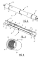
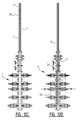
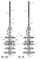
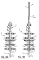
- An installation 1 for connecting a number of pipes 3 to form a pipe string 2 and/or disassembling a pipe string 2 into pipes 3 comprises a hollow body 4 which is placed on a borehole 5 and through which pipes 3 can be carried ( fig. 1 ).
- Hollow body 4 is formed by a stack of modules, including a number of blow-out preventers (BOPs) 6, 7, 8, i.e. hydraulically controllable valves, and two gate valves 9.
- BOPs blow-out preventers
- Each module 6-9 has a tubular channel 46, and these channels 46 together form a passage for pipe string 2.
- Such a stack of BOPs is often referred to as a "Christmas tree".
- Each BOP 6, 7 is provided on either side with hydraulic cylinders 10 in which pistons 11 which operate an active member or ram 12 are movable. These active members or rams 12 are formed differently depending on the function they fulfil.
- the different modules 5-9 are each provided at their outer ends with flanges 13, 14 which are attached liquid-tightly to each other, for instance by bolts.
- Installation 1 further comprises a stackable pipe or "lubricator" 15 mounted on the upper BOP 9.
- Installation 1 further comprises a lifting gear (not shown) with a hoisting cable 16 with which pipes 3 can be inserted into or lifted out of hollow body 4.
- a device 17 Suspended from hoisting cable 16 is a device 17 which is intended to engage on the upper outer end of pipe string 2 for connection thereof to hoisting cable 16.
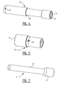
- This connecting system 18 comprises for each pair of successive pipes 3 a tubular coupling member 19 for arranging therebetween.
- the tubular coupling member 19 comprises a clamp or snap part 20 for arranging on one of the pipes 3 for connecting and a base part 21 co-acting therewith and for screwing onto the other of the pipes 3 for connecting ( fig. 2, 3 ).
- the clamp or snap part - here clamp part 20 - is provided with an end segment 22 with internal screw thread 23 with which it can be screwed round the narrowed outer end with external screw thread of one of the two pipes 3 to be connected to each other.
- Clamp part 20 is configured here to receive a narrowed outer end 24 with smooth outer surface of base part 21.
- This base part 21 has on the other side a widened outer end 25 with internal screw thread 26 with which it can be screwed onto the narrowed outer end with external screw thread of the other pipe 3.
- This widening 25 also defines a stop which bounds the insertion depth of base part 21 into clamp part 20.
- a movable clamping element 27 which in the shown example takes the form of a ring which substantially wholly encloses the outer surface of outer end 24 of base part 21.
- Clamping ring 27 has a gap 28 ( fig. 6 ) whereby it can be pressed together around outer end 24.
- Clamping ring 27 further has a tapering cross-section with a smooth outer side 29 and a rough inner side 30 which engages on the outer surface of base part 21.
- the outer side 29 of clamping ring 27 co-acts with an inner surface 31 of clamp part 20, which likewise takes a wedge-shaped form.
- Clamping ring 27 is thus pressed increasingly further together as it is moved in the direction of a mouth 32 of clamp part 20, whereby the rough inner side 30 thereof grips increasingly more strongly on base part 21. This prevents base part 21 being pulled out of clamp part 20.
- the inner side 30 of clamping ring 27 takes a sawtooth-like form in order to make the frictional force on outer end 24 as great as possible.
- clamping ring 27 lies loosely round the outer end 24 thereof in the tapering space bounded by the inclining inner surface 31.
- Base part 21 can hereby rotate in clamp part 20.
- End segment 22 of the tubular coupling member 19 is attached to the rest of coupling member 19 in the shown example such that the outer ends of pipes 3 can be detached from each other by exerting a great force such that coupling member 19 fails at the position of the connection to end segment 22. This prevents pipes 3 breaking or installation 1 being damaged.
- the connection intended as failure location is formed by three failing members 33, here bolts, which are screwed into openings 34 in clamp part 20 and openings 35 in end segment 22 in order to attach these two parts to each other.
- clamp member 20 does not consist of two parts connected by failing members, it is also possible to envisage a local weakening being formed therein by giving the wall or casing of clamp member 20 a thinner form locally or by forming a gap therein.
- clamp member 20 In the shown example the components of clamp member 20 are not purely cylindrical, but profiled. End segment 22 and clamp part 20 are thus each provided on their inner side with a peripheral groove 36 and 37 respectively. These grooves 36, 37, also referred to as fishing necks, serve for engagement by an internal tool 38 which forms part of engaging device 17 suspended from hoisting cable 16. This tool 39, with which coupling member 19 and the pipes 3 connected thereby are moved up or downward in borehole 5, is referred to as a running tool or pulling tool.
- clamp member 20 is provided on its outer side with a peripheral groove 38. This outer groove 38 serves for engagement by a fixation member of installation 1 to be discussed below.
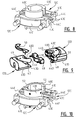
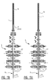
- modules of BOPs 6, 7 of installation 1 are provided with different types of active members or rams 12.
- the form, dimensions and embodiment of these rams 12 vary depending on the function they fulfil in respectively assembly and disassembly of pipe string 2.
- Rams 12A in the lower BOP 6 are thus so-called shear rams which serve to cut through a pipe string 2 and to close the hollow body 4 in the case of a sudden pressure buildup in borehole 5.
- These shear rams 12A are therefore provided with a cutting edge and are embodied so that together or individually they cover the whole cross-section of channel 46 in sealing manner.
- the associated cylinders 10A and pistons 11A also take a larger form than those of the other rams 12B-12E.
- rams 12B-12E are intended for co-action in some form or other with pipe string 2, and therefore all have a ring segment part 46, the dimensions of which are adapted to those of a relevant part of pipe string 2.
- Each ram 12C has a ring or tube segment 40C which is fixed to a bracket 41C, which is in turn fixed to a piston rod 42C of piston 11C.
- Each bracket 41C is provided with two grooves 43C, one of which carries two inserts 44C which can be received close-fittingly in a groove 43C of the opposite ram 12C.
- a strong connection between the two mutually facing rams 12C can in this way be effected when they are both extended into channel 46 of the associated BOP 7.
- Brackets 41C and tube segments 40C close the passage of channel 46 here so that only the internal section bounded by tube segments 40 still remains clear for throughfeed of components of pipe string 2.
- the dimensions selected for the ring or tube segments 40C are slightly larger here than the external diameter of pipes 3 but slightly smaller than the external diameter of coupling members 19.
- the upper pair of rams 12D in the double BOP 7 is intended as fixation members (holding rams) and is configured to engage on the narrowed part or groove 38 in the outer wall of coupling member 19.
- each ram 12D is provided with an insert 47 of a softer, somewhat deformable material which is received in a groove 48 extending over the whole width of bracket 41D and ring segment 40D.
- These rams 12D are also each provided with recesses 43D and protruding parts 44D which lie opposite each other and ensure a firm connection.
- Bracket 41D further has a groove 49 which, when rams 12D lie against each other, runs along the periphery of channel 46. Arranged in this groove 49 is a sealing member 50, likewise of a relatively softer and more readily deformable material than the rest of ram 12D.
- Rams 12E serve as release members (release rams) and are configured for co-action with tool 39 with which pipe string 2 is attached to hoisting cable 16.
- These rams 12E have a construction similar to that of rams 12C forming the support members, but are covered on the inner side of the ring or tube segments 40E with a slide layer 52 of wear-resistant material, for instance a plastic such as HMPE.
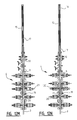
- a clamp part 20 of a coupling member 19 is then attached to a pipe 3 and this coupling member 19 is connected by means of an engaging device 17 to hoisting cable 16.
- the assembly of pipe 3, clamp part 20 and engaging device 17 is carried into a lubricator 15 which is closed on one side and which is then attached with its open end to the upper flange of hollow body 4 ( fig. 12B ).
- the pressure in the interior of lubricator 15 is then equalized to that in hollow body 4 and gate valve 9 is opened.
- the closed outer end of lubricator 15 now therefore forms the seal of the combination of hollow body 4 and lubricator 15 ( fig. 12C ).
- the hoisting cable 16 which extends through the closed outer end of lubricator 15, is then payed out until about half the pipe 3 has passed through the rams 12C functioning as support members.
- the weight of pipe 3 is measured and recorded here.
- Support members 12C are then extended into channel 46 by operating the associated hydraulic cylinders 10C and pistons 11C ( fig. 12D ).
- the ring or tube segments 40C now enclose pipe 3 with some play.
- the correct extent to which support members 12C extend can be monitored by measuring or marking the displacement of the relevant piston rods 42C.
- Hoisting cable 16 is subsequently payed out further so that pipe 3 sinks further into hollow body 4 until the bottom edge 51 of clamp part 20 comes to rest on support members 12C ( fig. 12E ).
- the upper edges 12D of the double BOP 7 are then extended into channel 46 by operating the associated hydraulic cylinders 10D and pistons 11D.
- These rams 12D form fixation members which, as stated, engage on the narrowed part or the groove 38 in the outer wall of clamp part 20.
- the correct extent of closure of fixation members 12D is here also measured or marked, for instance on the basis of the displacement of piston rods 42D ( fig. 12F ).
- the upper rams 12E are then extended and enclose engaging device 17 with their ring or tube segments 40E. Because the ring or tube segments 40E are covered with slide layer 52, components of engaging device 17 can be moved up and down to some extent herein when this engaging device 17 is released from pipe 3, so that these rams function as release members.
- engaging device 17 comprises a tool 39 which engages with its lower outer end in mouth 32 of clamping member 19.
- Tool 39 is provided with protrusions 53 which, through displacement of an internal wedge mechanism, are pressed outward and thus engage in groove 37 in clamp part 20. Protrusions 53 are fixed in the protruding position.
- the tool 39 is further provided with a breaking pin 45 and an internal striking mechanism or "jar". When the jar is operated the breaking pin 45 fails, whereby the different components of the wedge mechanism can be moved back to their starting position and protrusions 53 can be retracted. In this position the tool 39 can be taken out of the internal groove 37 of clamp part 20.
- the above discussed release rams 12E are in fact not necessary. These come into play only when use is made of a tool (not shown here) that is not provided with a jar.
- Lubricator 15 with the subsequent pipe part 3 therein can then be attached to hollow body 4 for the purpose of assembling a pipe string 2.
- the new pipe part 3 is attached on its upper side to clamp part 20.
- a base part 21 for co-action with clamp part 20 of the already placed pipe 3 ( fig. 12J ).
- the pressure in hollow body 4 and lubricator 15 is then once again equalized, and gate valve 9 opened.
- the closed end of lubricator 15 now thus once again forms the seal of borehole 5.
- Hoisting cable 16 is then payed out quickly, whereby pipe 3 with pipe part 21 on its lower end lands on clamp part 20 with a considerable force under the influence of its weight.
- Base part 21 protrudes here into clamping ring 27 of clamp part 20.
- clamping ring 27 is moved upward in clamp part 20 and pressed together increasingly tighter round base part 21.
- connection withstands this pulling test the fixation members or rams 12D are moved apart, whereby coupling member 19 is released.
- the thus assembled pipe string 2 is then raised to some extent by tensioning hoisting cable 16 and the weight of pipe string 2 is measured and recorded.
- Support members 12C are then moved apart ( fig. 12L ).
- Hoisting cable 16 is subsequently payed out so that pipe string 2 sinks through about half a pipe length (in this case about four metres) ( fig. 12M ).
- the centre of upper pipe 3 is then once again situated roughly at the height of support members 12C, just as in the situation of fig. 12D .
- Engaging device 17, the breaking pin 54 of which has after all failed, can then be removed again from hoisting cable 16 and replaced by a new engaging device 17 with new pipe 3 and new base part 21, after which the procedure can in fact be repeated from fig. 12J .
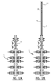
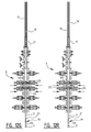
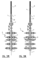
- Installation 1 can also be used to lift a pipe string 2 out of borehole 5 and disassemble it into individual pipes 3.
- the starting point here is a situation in which pipe string 2 is suspended from upper pipe 3 in borehole 5 ( fig. 13A ).
- Clamp part 20 rests here with its bottom edge 51 on the extended support members 12C, while pipe 3 is in addition held fast by a pair of rams 12B which are placed between support members 12C and shear rams 12A and which serve as lower fixation members (slip rams).
- hollow body 4 is closed by the upper gate valve 9.
- an engaging device 17 is first attached to hoisting cable 16 and received into lubricator 15 which is then attached to hollow body 4 ( fig. 13B ). The pressure in hollow body 4 and lubricator 15 is then equalized and gate valve 9 is opened ( fig. 13C ). Hosting cable 16 is subsequently payed out, whereby engaging device 17 lands on clamp part 20. The lower outer end of tool 39 engages here in clamp part 20 and is fixed in groove 37 ( fig. 13D ).
- the jar in tool 39 is then activated, whereby clamp part 20 is subjected to an impact load and the failing members 33 eventually fail. Clamp part 20 is thus separated from end segment 22, which remains attached to the upper side of pipe 3. Clamp part 20 is now lifted out of the hollow body and into lubricator 15 ( fig. 13E ), after which jar 15 is isolated from hollow body 4 and detached ( fig. 13F , G ). An engaging device with a smaller tool 39A - for instance with a nominal diameter of 2.5 inches where that of the larger tool can be 3 inches - is then attached to hoisting cable 16 and received in lubricator 15. Lubricator 15 is once again attached to hollow body 4 ( fig. 13H ), the pressure is equalized ( fig.
- fixation members 12B are detached and pipe string 2 is raised over a small part of a pipe length. The weight is measured and recorded here. Support members 12C are then moved apart, whereby pipe string 2 hangs completely freely in hollow body 4, supported only by hoisting cable 16 ( fig. 13K ). Pipe string 2 is then raised so far that the following coupling member 19 between two pipes 3 is situated above support members 12C. This is checked on the basis of a measurement of the length of retracted hoisting cable ( fig. 13L ). Support members 12C are then extended again ( fig. 13M ) and the pipe string is lowered until it rests with bottom edge 51 of coupling member 19 on support members 12C. The lower fixation members 12B are then extended and once again engage on the wall of pipe 3 ( fig. 13N ).
- a pipe string 2 can thus be assembled or disassembled in rapid and simple manner. Operation can take place very quickly through the use of the clamp connection between two parts 20, 21 of coupling member 19, which can each be pre-attached to a corresponding pipe part 3. Failing pins 33 in coupling member 19 on the other hand make it possible to also take the pipes 3 apart again quickly and easily without the danger of damage being caused to pipes 3, to the actual coupling member 19 or to the rest of installation 1.
Landscapes
- Engineering & Computer Science (AREA)
- Life Sciences & Earth Sciences (AREA)
- Geology (AREA)
- Mining & Mineral Resources (AREA)
- Physics & Mathematics (AREA)
- Environmental & Geological Engineering (AREA)
- Fluid Mechanics (AREA)
- General Life Sciences & Earth Sciences (AREA)
- Geochemistry & Mineralogy (AREA)
- Mechanical Engineering (AREA)
- Earth Drilling (AREA)
Applications Claiming Priority (1)
| Application Number | Priority Date | Filing Date | Title |
|---|---|---|---|
| NL2010867A NL2010867C2 (nl) | 2013-05-27 | 2013-05-27 | Werkwijze en installatie voor het vormen of demonteren van een buisstreng en daarbij toe te passen koppelorgaan. |
Publications (1)
| Publication Number | Publication Date |
|---|---|
| EP2808481A1 true EP2808481A1 (de) | 2014-12-03 |
Family
ID=49517573
Family Applications (1)
| Application Number | Title | Priority Date | Filing Date |
|---|---|---|---|
| EP13195492.7A Withdrawn EP2808481A1 (de) | 2013-05-27 | 2013-12-03 | Verfahren und Anlage zur Montage oder Demontage eines Rohrstrangs und Kopplungselement zur Verwendung darin |
Country Status (2)
| Country | Link |
|---|---|
| EP (1) | EP2808481A1 (de) |
| NL (2) | NL2010867C2 (de) |
Cited By (2)
| Publication number | Priority date | Publication date | Assignee | Title |
|---|---|---|---|---|
| CN105952394A (zh) * | 2016-06-21 | 2016-09-21 | 崔斌 | 一种油气田带压修井作业专用吊卡结构 |
| US11319769B2 (en) | 2020-04-30 | 2022-05-03 | Saudi Arabian Oil Company | Multi-intervention blowout preventer and methods of use thereof |
Citations (9)
| Publication number | Priority date | Publication date | Assignee | Title |
|---|---|---|---|---|
| US2721614A (en) * | 1952-04-17 | 1955-10-25 | Drury M Simmons | Systems and structure for controlling the movement of well pipe in well bores |
| US3100015A (en) * | 1959-10-05 | 1963-08-06 | Regan Forge & Eng Co | Method of and apparatus for running equipment into and out of wells |
| US3322443A (en) * | 1964-04-17 | 1967-05-30 | Brown Oil Tools | Quick coupling device for tubular bodies |
| US3361453A (en) * | 1965-07-02 | 1968-01-02 | Brown Oil Tools | Quick coupling device |
| US3999610A (en) * | 1974-11-21 | 1976-12-28 | Otis Engineering Corporation | Pipe snubbing method and apparatus |
| US4119297A (en) * | 1977-03-14 | 1978-10-10 | Gunther Albert W | Snubbing apparatus |
| GB2141509A (en) * | 1983-06-17 | 1984-12-19 | Slope Indicator Co | Coupling for tubular members |
| US5176406A (en) * | 1990-12-20 | 1993-01-05 | Straghan Robert G | Coupling |
| NL1034936C2 (nl) * | 2008-01-21 | 2009-07-22 | Balance Point Control B V | Werkwijze voor het vormen van een buisstreng en daarbij toe te passen buisvormig verbindingsorgaan. |
-
2013
- 2013-05-27 NL NL2010867A patent/NL2010867C2/nl not_active IP Right Cessation
- 2013-12-03 EP EP13195492.7A patent/EP2808481A1/de not_active Withdrawn
-
2014
- 2014-11-27 NL NL2013895A patent/NL2013895C2/nl not_active IP Right Cessation
Patent Citations (9)
| Publication number | Priority date | Publication date | Assignee | Title |
|---|---|---|---|---|
| US2721614A (en) * | 1952-04-17 | 1955-10-25 | Drury M Simmons | Systems and structure for controlling the movement of well pipe in well bores |
| US3100015A (en) * | 1959-10-05 | 1963-08-06 | Regan Forge & Eng Co | Method of and apparatus for running equipment into and out of wells |
| US3322443A (en) * | 1964-04-17 | 1967-05-30 | Brown Oil Tools | Quick coupling device for tubular bodies |
| US3361453A (en) * | 1965-07-02 | 1968-01-02 | Brown Oil Tools | Quick coupling device |
| US3999610A (en) * | 1974-11-21 | 1976-12-28 | Otis Engineering Corporation | Pipe snubbing method and apparatus |
| US4119297A (en) * | 1977-03-14 | 1978-10-10 | Gunther Albert W | Snubbing apparatus |
| GB2141509A (en) * | 1983-06-17 | 1984-12-19 | Slope Indicator Co | Coupling for tubular members |
| US5176406A (en) * | 1990-12-20 | 1993-01-05 | Straghan Robert G | Coupling |
| NL1034936C2 (nl) * | 2008-01-21 | 2009-07-22 | Balance Point Control B V | Werkwijze voor het vormen van een buisstreng en daarbij toe te passen buisvormig verbindingsorgaan. |
Cited By (2)
| Publication number | Priority date | Publication date | Assignee | Title |
|---|---|---|---|---|
| CN105952394A (zh) * | 2016-06-21 | 2016-09-21 | 崔斌 | 一种油气田带压修井作业专用吊卡结构 |
| US11319769B2 (en) | 2020-04-30 | 2022-05-03 | Saudi Arabian Oil Company | Multi-intervention blowout preventer and methods of use thereof |
Also Published As
| Publication number | Publication date |
|---|---|
| NL2013895C2 (nl) | 2015-07-07 |
| NL2013895A (nl) | 2015-02-09 |
| NL2010867C2 (nl) | 2014-12-17 |
Similar Documents
| Publication | Publication Date | Title |
|---|---|---|
| US9181782B2 (en) | Apparatus and method for isolating a section of a pipe riser bore in the course of riser renewal | |
| US8573312B2 (en) | Apparatus for applying an axial force to well pipe slips | |
| US20110005777A1 (en) | Tool storage assembly | |
| US8915676B2 (en) | Subsea clamp connector emergency release tool and method | |
| BRPI0717865A2 (pt) | Módulo cortador para seccionar um duto em um poço, método para seccionar um duto em um poço, sistema, método, e aparelho | |
| US20100139921A1 (en) | Cutting Device and a Method for Emergency Cutting of a Line in a Well | |
| BR112018004641B1 (pt) | Aparelho para reter temporariamente uma corda tensionada, método para reter uma corda tensionada, método de liberação de uma corda tensionada e método para conectar um item adicional de equipamento entre seções de corda | |
| CA2958296C (en) | Drive off method from subsea well with pipe retention capability | |
| EP2808481A1 (de) | Verfahren und Anlage zur Montage oder Demontage eines Rohrstrangs und Kopplungselement zur Verwendung darin | |
| RU2694453C1 (ru) | Устройство для спуска кабеля в скважину | |
| AU2014203399A1 (en) | Apparatus and Method for the Installation or Removal of a Rotary Control Device Insert or a Component Thereof | |
| CA2845974C (en) | Rotatable tubing hanger | |
| DK2989285T3 (en) | SYSTEM AND PROCEDURE FOR SPLITING A NON-ROLLABLE TOOLS LOCATED ALONG A COILED TUBING STRING | |
| US10895125B2 (en) | Completion interface systems for use with surface BOPS | |
| AU2020247075B2 (en) | Enhanced method for cutting pipes on a drill floor and tool therefor | |
| US7431077B2 (en) | Cable hanger for use in a cable guided fishing assembly | |
| US20150136417A1 (en) | Method for handling tubulars and rigidizer therefor | |
| CN209924958U (zh) | 带压作业管柱内腔的小型快速提缆器 | |
| US20140034333A1 (en) | Lifting device and method | |
| US20140294512A1 (en) | Powered Slip Actuation | |
| GB2553423A (en) | Device and method for suspending loads from a bail of an elevator of a drilling rig, and corresponding drilling rig assembly | |
| NO20131685A1 (no) | Fremgangsmåte og maskineri for operasjoner på, i eller gjennom en rørstruktur | |
| RU2021493C1 (ru) | Способ ликвидации нефтегазопроявлений при нахождении в скважине кабеля и устройство для его осуществления |
Legal Events
| Date | Code | Title | Description |
|---|---|---|---|
| PUAI | Public reference made under article 153(3) epc to a published international application that has entered the european phase |
Free format text: ORIGINAL CODE: 0009012 |
|
| 17P | Request for examination filed |
Effective date: 20131203 |
|
| AK | Designated contracting states |
Kind code of ref document: A1 Designated state(s): AL AT BE BG CH CY CZ DE DK EE ES FI FR GB GR HR HU IE IS IT LI LT LU LV MC MK MT NL NO PL PT RO RS SE SI SK SM TR |
|
| AX | Request for extension of the european patent |
Extension state: BA ME |
|
| R17P | Request for examination filed (corrected) |
Effective date: 20150603 |
|
| RBV | Designated contracting states (corrected) |
Designated state(s): AL AT BE BG CH CY CZ DE DK EE ES FI FR GB GR HR HU IE IS IT LI LT LU LV MC MK MT NL NO PL PT RO RS SE SI SK SM TR |
|
| STAA | Information on the status of an ep patent application or granted ep patent |
Free format text: STATUS: THE APPLICATION IS DEEMED TO BE WITHDRAWN |
|
| 18D | Application deemed to be withdrawn |
Effective date: 20160701 |