EP2948072B1 - Deckel für implantate und implantatanordnungen - Google Patents
Deckel für implantate und implantatanordnungen Download PDFInfo
- Publication number
- EP2948072B1 EP2948072B1 EP14703487.0A EP14703487A EP2948072B1 EP 2948072 B1 EP2948072 B1 EP 2948072B1 EP 14703487 A EP14703487 A EP 14703487A EP 2948072 B1 EP2948072 B1 EP 2948072B1
- Authority
- EP
- European Patent Office
- Prior art keywords
- cap
- implant
- cavity
- bone
- shell
- Prior art date
- Legal status (The legal status is an assumption and is not a legal conclusion. Google has not performed a legal analysis and makes no representation as to the accuracy of the status listed.)
- Not-in-force
Links
- 239000007943 implant Substances 0.000 title claims description 99
- 230000000712 assembly Effects 0.000 title 1
- 238000000429 assembly Methods 0.000 title 1
- 210000000988 bone and bone Anatomy 0.000 claims description 109
- 230000007246 mechanism Effects 0.000 claims description 32
- 230000037431 insertion Effects 0.000 claims 1
- 238000003780 insertion Methods 0.000 claims 1
- POIUWJQBRNEFGX-XAMSXPGMSA-N cathelicidin Chemical compound C([C@@H](C(=O)N[C@@H](CCCNC(N)=N)C(=O)N[C@@H](CCCCN)C(=O)N[C@@H](CO)C(=O)N[C@@H](CCCCN)C(=O)N[C@@H](CCC(O)=O)C(=O)N[C@@H](CCCCN)C(=O)N[C@@H]([C@@H](C)CC)C(=O)NCC(=O)N[C@@H](CCCCN)C(=O)N[C@@H](CCC(O)=O)C(=O)N[C@@H](CC=1C=CC=CC=1)C(=O)N[C@@H](CCCCN)C(=O)N[C@@H](CCCNC(N)=N)C(=O)N[C@@H]([C@@H](C)CC)C(=O)N[C@@H](C(C)C)C(=O)N[C@@H](CCC(N)=O)C(=O)N[C@@H](CCCNC(N)=N)C(=O)N[C@@H]([C@@H](C)CC)C(=O)N[C@@H](CCCCN)C(=O)N[C@@H](CC(O)=O)C(=O)N[C@@H](CC=1C=CC=CC=1)C(=O)N[C@@H](CC(C)C)C(=O)N[C@@H](CCCNC(N)=N)C(=O)N[C@@H](CC(N)=O)C(=O)N[C@@H](CC(C)C)C(=O)N[C@@H](C(C)C)C(=O)N1[C@@H](CCC1)C(=O)N[C@@H](CCCNC(N)=N)C(=O)N[C@@H]([C@@H](C)O)C(=O)N[C@@H](CCC(O)=O)C(=O)N[C@@H](CO)C(O)=O)NC(=O)[C@H](CC=1C=CC=CC=1)NC(=O)[C@H](CC(O)=O)NC(=O)CNC(=O)[C@H](CC(C)C)NC(=O)[C@@H](N)CC(C)C)C1=CC=CC=C1 POIUWJQBRNEFGX-XAMSXPGMSA-N 0.000 description 12
- 230000007794 irritation Effects 0.000 description 7
- 210000004872 soft tissue Anatomy 0.000 description 7
- 230000008878 coupling Effects 0.000 description 5
- 238000010168 coupling process Methods 0.000 description 5
- 238000005859 coupling reaction Methods 0.000 description 5
- 238000000034 method Methods 0.000 description 3
- 230000004048 modification Effects 0.000 description 3
- 238000012986 modification Methods 0.000 description 3
- 239000000463 material Substances 0.000 description 2
- 210000001562 sternum Anatomy 0.000 description 2
- 241001269524 Dura Species 0.000 description 1
- 238000007792 addition Methods 0.000 description 1
- 230000004075 alteration Effects 0.000 description 1
- 210000003484 anatomy Anatomy 0.000 description 1
- 210000004204 blood vessel Anatomy 0.000 description 1
- 238000002513 implantation Methods 0.000 description 1
- 230000008676 import Effects 0.000 description 1
- 210000002050 maxilla Anatomy 0.000 description 1
- 210000003205 muscle Anatomy 0.000 description 1
- 210000005036 nerve Anatomy 0.000 description 1
- 238000006467 substitution reaction Methods 0.000 description 1
- 210000001519 tissue Anatomy 0.000 description 1
- 239000011800 void material Substances 0.000 description 1
Images


Classifications
-
- A—HUMAN NECESSITIES
- A61—MEDICAL OR VETERINARY SCIENCE; HYGIENE
- A61B—DIAGNOSIS; SURGERY; IDENTIFICATION
- A61B17/00—Surgical instruments, devices or methods
- A61B17/56—Surgical instruments or methods for treatment of bones or joints; Devices specially adapted therefor
- A61B17/58—Surgical instruments or methods for treatment of bones or joints; Devices specially adapted therefor for osteosynthesis, e.g. bone plates, screws or setting implements
- A61B17/68—Internal fixation devices, including fasteners and spinal fixators, even if a part thereof projects from the skin
- A61B17/685—Elements to be fitted on the end of screws or wires, e.g. protective caps
-
- A—HUMAN NECESSITIES
- A61—MEDICAL OR VETERINARY SCIENCE; HYGIENE
- A61B—DIAGNOSIS; SURGERY; IDENTIFICATION
- A61B17/00—Surgical instruments, devices or methods
- A61B17/56—Surgical instruments or methods for treatment of bones or joints; Devices specially adapted therefor
- A61B17/58—Surgical instruments or methods for treatment of bones or joints; Devices specially adapted therefor for osteosynthesis, e.g. bone plates, screws or setting implements
- A61B17/68—Internal fixation devices, including fasteners and spinal fixators, even if a part thereof projects from the skin
- A61B17/70—Spinal positioners or stabilisers, e.g. stabilisers comprising fluid filler in an implant
- A61B17/7001—Screws or hooks combined with longitudinal elements which do not contact vertebrae
- A61B17/7032—Screws or hooks with U-shaped head or back through which longitudinal rods pass
-
- A—HUMAN NECESSITIES
- A61—MEDICAL OR VETERINARY SCIENCE; HYGIENE
- A61B—DIAGNOSIS; SURGERY; IDENTIFICATION
- A61B17/00—Surgical instruments, devices or methods
- A61B17/56—Surgical instruments or methods for treatment of bones or joints; Devices specially adapted therefor
- A61B17/58—Surgical instruments or methods for treatment of bones or joints; Devices specially adapted therefor for osteosynthesis, e.g. bone plates, screws or setting implements
- A61B17/68—Internal fixation devices, including fasteners and spinal fixators, even if a part thereof projects from the skin
- A61B17/80—Cortical plates, i.e. bone plates; Instruments for holding or positioning cortical plates, or for compressing bones attached to cortical plates
- A61B17/8033—Cortical plates, i.e. bone plates; Instruments for holding or positioning cortical plates, or for compressing bones attached to cortical plates having indirect contact with screw heads, or having contact with screw heads maintained with the aid of additional components, e.g. nuts, wedges or head covers
- A61B17/8042—Cortical plates, i.e. bone plates; Instruments for holding or positioning cortical plates, or for compressing bones attached to cortical plates having indirect contact with screw heads, or having contact with screw heads maintained with the aid of additional components, e.g. nuts, wedges or head covers the additional component being a cover over the screw head
-
- A—HUMAN NECESSITIES
- A61—MEDICAL OR VETERINARY SCIENCE; HYGIENE
- A61B—DIAGNOSIS; SURGERY; IDENTIFICATION
- A61B17/00—Surgical instruments, devices or methods
- A61B17/56—Surgical instruments or methods for treatment of bones or joints; Devices specially adapted therefor
- A61B17/58—Surgical instruments or methods for treatment of bones or joints; Devices specially adapted therefor for osteosynthesis, e.g. bone plates, screws or setting implements
- A61B17/68—Internal fixation devices, including fasteners and spinal fixators, even if a part thereof projects from the skin
- A61B17/82—Internal fixation devices, including fasteners and spinal fixators, even if a part thereof projects from the skin for bone cerclage
- A61B17/823—Internal fixation devices, including fasteners and spinal fixators, even if a part thereof projects from the skin for bone cerclage for the sternum
-
- A—HUMAN NECESSITIES
- A61—MEDICAL OR VETERINARY SCIENCE; HYGIENE
- A61B—DIAGNOSIS; SURGERY; IDENTIFICATION
- A61B17/00—Surgical instruments, devices or methods
- A61B17/56—Surgical instruments or methods for treatment of bones or joints; Devices specially adapted therefor
- A61B17/58—Surgical instruments or methods for treatment of bones or joints; Devices specially adapted therefor for osteosynthesis, e.g. bone plates, screws or setting implements
- A61B17/68—Internal fixation devices, including fasteners and spinal fixators, even if a part thereof projects from the skin
- A61B17/84—Fasteners therefor or fasteners being internal fixation devices
- A61B17/844—Fasteners therefor or fasteners being internal fixation devices with expandable anchors or anchors having movable parts
-
- A—HUMAN NECESSITIES
- A61—MEDICAL OR VETERINARY SCIENCE; HYGIENE
- A61C—DENTISTRY; APPARATUS OR METHODS FOR ORAL OR DENTAL HYGIENE
- A61C7/00—Orthodontics, i.e. obtaining or maintaining the desired position of teeth, e.g. by straightening, evening, regulating, separating, or by correcting malocclusions
- A61C7/10—Devices having means to apply outwardly directed force, e.g. expanders
-
- A—HUMAN NECESSITIES
- A61—MEDICAL OR VETERINARY SCIENCE; HYGIENE
- A61C—DENTISTRY; APPARATUS OR METHODS FOR ORAL OR DENTAL HYGIENE
- A61C7/00—Orthodontics, i.e. obtaining or maintaining the desired position of teeth, e.g. by straightening, evening, regulating, separating, or by correcting malocclusions
- A61C7/12—Brackets; Arch wires; Combinations thereof; Accessories therefor
- A61C7/125—Mouth tissue protecting means, e.g. bracket caps
-
- A—HUMAN NECESSITIES
- A61—MEDICAL OR VETERINARY SCIENCE; HYGIENE
- A61C—DENTISTRY; APPARATUS OR METHODS FOR ORAL OR DENTAL HYGIENE
- A61C8/00—Means to be fixed to the jaw-bone for consolidating natural teeth or for fixing dental prostheses thereon; Dental implants; Implanting tools
-
- A—HUMAN NECESSITIES
- A61—MEDICAL OR VETERINARY SCIENCE; HYGIENE
- A61B—DIAGNOSIS; SURGERY; IDENTIFICATION
- A61B17/00—Surgical instruments, devices or methods
- A61B17/56—Surgical instruments or methods for treatment of bones or joints; Devices specially adapted therefor
- A61B17/58—Surgical instruments or methods for treatment of bones or joints; Devices specially adapted therefor for osteosynthesis, e.g. bone plates, screws or setting implements
- A61B17/60—Surgical instruments or methods for treatment of bones or joints; Devices specially adapted therefor for osteosynthesis, e.g. bone plates, screws or setting implements for external osteosynthesis, e.g. distractors, contractors
- A61B17/66—Alignment, compression or distraction mechanisms
-
- A—HUMAN NECESSITIES
- A61—MEDICAL OR VETERINARY SCIENCE; HYGIENE
- A61B—DIAGNOSIS; SURGERY; IDENTIFICATION
- A61B17/00—Surgical instruments, devices or methods
- A61B17/56—Surgical instruments or methods for treatment of bones or joints; Devices specially adapted therefor
- A61B17/58—Surgical instruments or methods for treatment of bones or joints; Devices specially adapted therefor for osteosynthesis, e.g. bone plates, screws or setting implements
- A61B17/68—Internal fixation devices, including fasteners and spinal fixators, even if a part thereof projects from the skin
- A61B17/82—Internal fixation devices, including fasteners and spinal fixators, even if a part thereof projects from the skin for bone cerclage
-
- A—HUMAN NECESSITIES
- A61—MEDICAL OR VETERINARY SCIENCE; HYGIENE
- A61B—DIAGNOSIS; SURGERY; IDENTIFICATION
- A61B17/00—Surgical instruments, devices or methods
- A61B17/56—Surgical instruments or methods for treatment of bones or joints; Devices specially adapted therefor
- A61B17/58—Surgical instruments or methods for treatment of bones or joints; Devices specially adapted therefor for osteosynthesis, e.g. bone plates, screws or setting implements
- A61B17/68—Internal fixation devices, including fasteners and spinal fixators, even if a part thereof projects from the skin
- A61B17/84—Fasteners therefor or fasteners being internal fixation devices
- A61B17/842—Flexible wires, bands or straps
-
- A—HUMAN NECESSITIES
- A61—MEDICAL OR VETERINARY SCIENCE; HYGIENE
- A61B—DIAGNOSIS; SURGERY; IDENTIFICATION
- A61B90/00—Instruments, implements or accessories specially adapted for surgery or diagnosis and not covered by any of the groups A61B1/00 - A61B50/00, e.g. for luxation treatment or for protecting wound edges
- A61B90/10—Instruments, implements or accessories specially adapted for surgery or diagnosis and not covered by any of the groups A61B1/00 - A61B50/00, e.g. for luxation treatment or for protecting wound edges for stereotaxic surgery, e.g. frame-based stereotaxis
- A61B2090/103—Cranial plugs for access to brain
-
- A—HUMAN NECESSITIES
- A61—MEDICAL OR VETERINARY SCIENCE; HYGIENE
- A61F—FILTERS IMPLANTABLE INTO BLOOD VESSELS; PROSTHESES; DEVICES PROVIDING PATENCY TO, OR PREVENTING COLLAPSING OF, TUBULAR STRUCTURES OF THE BODY, e.g. STENTS; ORTHOPAEDIC, NURSING OR CONTRACEPTIVE DEVICES; FOMENTATION; TREATMENT OR PROTECTION OF EYES OR EARS; BANDAGES, DRESSINGS OR ABSORBENT PADS; FIRST-AID KITS
- A61F2/00—Filters implantable into blood vessels; Prostheses, i.e. artificial substitutes or replacements for parts of the body; Appliances for connecting them with the body; Devices providing patency to, or preventing collapsing of, tubular structures of the body, e.g. stents
- A61F2/02—Prostheses implantable into the body
- A61F2/30—Joints
- A61F2/30721—Accessories
- A61F2/30744—End caps, e.g. for closing an endoprosthetic cavity
Definitions
- a cap can be configured to be coupled to an implant having an implant body.
- the cap can include a cap body that includes a shell having at least one side wall that defines at least a first inner surface and a second inner surface that is spaced from the first inner surface along a first direction.
- the first and second inner surfaces can at least partially define a cavity that is sized to receive at least a portion of the implant body such that the shell flexes between a first position and a second position as the cavity receives the at least a portion of the implant body.
- the cap can further include an attachment mechanism that is configured to abut an inner surface of the implant when the shell is in the second position to thereby trap the at least a portion of the implant body within the cavity.
- an implant assembly can include an implant configured to be coupled to at least one bone part.
- the implant can include an implant body that defines at least one unsmooth surface.
- the assembly can further include a cap configured to be coupled to the implant body such that the cap overlies the at least one unsmooth surface.
- the cap can include a shell that defines a cavity that is configured to receive at least a portion of the implant body such that the shell flexes relative to the implant body as the cavity receives the at least a portion of the implant body to thereby couple the cap to the implant.
- the cap defines an outer surface that is curved.
- a method of fixing a first bone part relative to a second bone part can include the steps of fixing a first bone part relative to a second bone part with an implant that defines a bone facing surface and an opposed outer surface; positioning a cap defining a curved outer surface over the outer surface of the implant, the cap having a shell that defines a cavity, the cap further having at least one attachment member that extends from the shell; and moving the cap toward the implant such that the cavity receives a portion of the implant and until the at least one attachment member abuts the bone facing surface to thereby couple the cap to the implant.
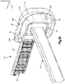
- an implant assembly 10 can include an implant, illustrated as a bone fixation member 14 that is configured to be coupled to at least one bone part and a cap 18 that is configured to be coupled to the bone fixation member 14.
- the bone fixation member 14 is configured to secure first and second bone parts of a target bone, such as a sternum, that are separated at a fracture location together in a compressed approximated position.
- the bone fixation member 14 can be substantially configured as a cable tie, and extends horizontally along a longitudinal direction L and a lateral direction A, and vertically along a transverse direction T.
- the bone fixation member 14 includes a flexible strap 22 that is elongate along the longitudinal direction and an implant body that is configured as a locking head 26 that extends from an end of the strap 22 along the longitudinal direction L.
- the locking head can define an inner surface 24 such as a bone facing surface, an outer surface 25, a slot 27 that extends through the locking head 26 from the bone facing surface 24 to the outer surface 25.
- the locking head can further include at least one locking tooth 28 that extends into the slot 27.
- the strap 22 can define a plurality of teeth 23 that are configured to engage the at least one tooth 28 of the locking head 26 as the strap 22 translates through the slot 27.
- the implant body or locking head 26 can be substantially box shaped so as to define at least one unsmooth surface 30. For example, because the locking head 26 is substantially box shaped, edges of the locking head can be sharp or otherwise non-rounded. Therefore, it can be said that the locking head 26 has at least one unsmooth surface 30.
- the bone facing surface 24 is the bottom surface of the locking head 26 and the at least one unsmooth surface 30 of the locking head 26 is the top surface. It should be appreciated, however, that the bone facing surface 24 can be any surface that faces the bone and that the at least one unsmooth surface 30 can be any surface on the locking head 26. Further, it should be appreciated, that an unsmooth surface 30 can be any surface that is segmented, or otherwise interrupted, any surface that includes sharp edges, or any surface that includes a protuberance, for example.
- the cap 18 can be configured to be coupled to the locking head 26, such that the cap 18 overlies the locking head or at least the unsmooth surface 30 to thereby eliminate the unsmooth surface and/or reduce the palpability of the locking head 26. Therefore, the cap 18 can be configured to remove sharp edges from and/or reduce the palpability of the locking head 26 when coupled to the locking head 26. As shown in Figs. 1A and 1B the cap 18 includes a cap body 34 that is curved or otherwise rounded so as to reduce irritation that may be caused to the surrounding soft tissue by the locking head 26. The cap body 34 defines a first or upper end 38 and a second or lower end 42 that is spaced from the first end 38 along the transverse direction.
- the cap body 34 further includes a cavity 46 that extends into the lower end 42.
- the cavity 46 is configured to receive at least a portion of, such as a major portion of the locking head 26. It should be appreciated, however, that the cavity 46 can be configured to receive any locking head, as desired.
- the first end 38 of the cap body 34 defines an upper surface 50 and the second end 42 of the cap body 34 defines a lower surface 54.
- the cap body 34 further defines two opposed side surfaces 58 that merge into the upper and lower surfaces 50 and 54.
- the cap body 34 is curved, or otherwise rounded along the longitudinal direction L and includes a distal body end 64 and a proximal body end 68 spaced from the distal body end 64 along the longitudinal direction L.
- the cap body 34 can be curved from a location between the distal and proximal body ends 64 and 68 to the proximal body end 68. Therefore, the upper surface 50 is substantially convex along the longitudinal direction L.
- the upper surface 50 is curved such that the slope of the upper surface 50 increases as the upper surface 50 extends toward the proximal body end 68.
- the cap body 34 can define an outer shell 80 and an inner shell 84 disposed within the outer shell 80.
- the inner shell 84 includes a ceiling 70 and at least one side wall 74 that extends down from the first end 38 and defines at least a first inner surface 75a and a second inner surface 75b that is spaced from and substantially faces the first inner surface 75a along a first direction (e.g. the lateral direction) such that the ceiling 70 and the first and second inner surfaces 75a and 75b at least partially define the cavity 46.
- the at least one side wall 74 defines a third surface 75c that joins the first surface 75a to the second surface 75b such that the first, second, and third surfaces 75a-75c are continuous.
- the inner shell 84 can include three side walls that each defines the respective inner surfaces 75a-75c.
- the second inner surface 75b can face the first inner surface 75a such that a line that is orthogonal to the second inner surface 75a extends toward the first inner surface or at least has a directional component that extends toward the first inner surface. Therefore, the first and second inner surfaces 75a and 75b can define planes that are parallel to each other or can define planes that are oblique to each other and still substantially face each other.
- the distal end of the cap body 34 defines an opening 78 that extends into the cavity 46.
- the ceiling 70 and the at least one side wall 74 are configured to cover the locking head 26 when the locking head 26 is received within the cavity 46, and the opening 78 is configured to allow the strap 22 to extend through the opening 78 when the locking head 26 is received within the cavity 46.
- the outer shell 80 can define an inner surface 92 and the inner shell 84 can further define an outer surface 96 that faces and is spaced apart from the inner surface 92 along at least a portion of the surfaces 92 and 96. Because inner and outer surfaces 92 and 96 of the outer and inner shells 80 and 84, respectively, are spaced from each other, the inner shell 84 is configured to elastically flex relative to the outer shell 80 as the cavity 46 receives the locking head 26. That is, the side walls 74 of the inner shell 84 are configured to elastically flex outwardly between a first position and a second position as the cavity 46 receives the locking head 26. It should be appreciated, however, that the inner shell 84 can be configured to be non-flexible. Moreover, it should be appreciated, that the cap body 34 can be void of the inner shell 84 and can define an outer shell that defines the cavity 46.
- the cap 18 can further include an attachment mechanism that is configured to couple the cap 18 to the locking head 26.
- the attachment mechanism includes at least one, such as a first and a second attachment member 100 that are configured to couple the cap 18 to the locking head 26.
- the attachment mechanism or each attachment member 100 can be defined by or otherwise extend from the at least one side wall 74 substantially along the first direction.
- the first and second attachment members 100 extend toward each other into the cavity 46 from a location that is proximate to the lower end 32 and are opposed to each other along the first direction.
- the attachment members 100 can each define an abutment surface 104 that faces the ceiling 70 of the cavity 36 such that when the cap 18 is coupled to the locking head 26 the abutment surfaces 104 abut the bone facing surfaces 24 of the locking head 26 to thereby trap or otherwise secure the locking head within the cavity 46.
- the attachment members can include other configurations.
- the attachment members 100 can define C-clips.
- the cap 18 can include features other than the attachment members 100 that are configured to couple the cap 18 to the locking head 26.
- the attachment mechanism can be a surface of the at least one side wall 74 such that the surface creates a frictional fit with the locking head or the attachment mechanism can be a fixation member such as a needle.
- the first and second attachment members 100 can be configured to abut respective bone facing surfaces of the locking head.
- a bone fixation members 14 may be placed about the bone segments and of the sternum between adjacent ribs and the strap 22 can be pulled through the slot 27.
- the locking teeth 28 and 23 can engage to prevent the tension that is induced in the strap 22 from causing the strap 22 to back out of the slot 27.
- the free end of the bone fixation member 14 can be cut off. After the free end is removed, the cap 18 can be coupled to the locking head 26 to thereby smooth out the sharp edges of the locking head 26.
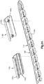
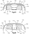
- an implant assembly 110 can include an implant, illustrated as a bone plate 114 that is configured to be coupled to at least one bone part, a first cap 118a and/or a second cap 118b that are both configured to be coupled to the bone plate 114.
- the bone plate 114 is configured to secure first and second bone parts that are separated at a fracture location together in a compressed approximated position.
- the bone plate 114 can include a plate body 126 that defines an inner surface 124 such as a bone facing surface, an opposed outer surface 125, and a plurality of bone fixation apertures 127 that extend through the plate body 126 from the bone facing surface 124 to the outer surface 125.
- the plate body 126 can further include at least one bone fixation element that extends through one of the bone fixation apertures 127 and into one of the bone parts to thereby couple the bone plate 114 to the bone part.
- the plate body 126 can be substantially box shaped so as to define at least one unsmooth surface 130.
- edges of the plate body 126 can be sharp or otherwise non-rounded. Therefore, it can be said that the plate body 126 has at least one unsmooth surface 130.
- the bone fixation element that extends through one of the bone fixation apertures 1 27 can also define the at least one unsmooth surface 130.
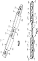
- the cap 118a can be configured to be coupled to the plate body 126, such that the cap 118a overlies the plate body 126 or at least the unsmooth surface 130 to thereby eliminate the unsmooth surface and/or reduce the palpability of the plate body 126. Therefore, the cap 118a can be configured to remove sharp edges from and/or reduce the palpability of the plate body 126 when coupled to the plate body 126. As shown in Fig. 2A the cap 118a includes a cap body 134a that is curved or otherwise rounded so as to reduce irritation that may be caused to the surrounding soft tissue by the plate body 126.
- the cap body 134a defines a first or upper end 138a and a second or lower end 142a that is spaced from the first end 138a along the transverse direction.
- the cap body 134a further includes a cavity 146a that extends into the lower end 142a.
- the cavity 146a is configured to receive at least a portion of the plate body 126.
- the first end 138a of the cap body 134a defines an upper surface 150a that is curved, or otherwise rounded along the lateral direction A and includes a distal body end 164a and a proximal body end 168a spaced from the distal body end 164a along the longitudinal direction L.
- the cap body 134a can be curved along the lateral direction so as to define a convex outer surface 150a.
- the upper surface 150a is curved such that the slope of the upper surface 150a increases as the upper surface 150a extends laterally in opposite directions from a centerline of the upper surface 150a.
- the cap body 134a can define an outer shell 180a and an inner shell 184a disposed within the outer shell 180a.
- the inner shell 184a includes a ceiling 170a and at least two side walls 174a that extend down from the first end 138a and define at least a first inner surface 175a and a second inner surface 175b that is spaced from and substantially faces the first inner surface 175a along a first direction (e.g. the lateral direction) such that the ceiling 170a and the first and second inner surfaces 175a and 175b at least partially define the cavity 146a.
- the inner shell 184a includes a first side wall 174a and a second side wall 174a that is spaced from the first side wall 174a such that the first inner surface 175a is parallel to the second inner surface 175b.
- the ceiling 170a defines a recess 171 that is configured to receive a portion of a bone fixation element head when the cap 118a is coupled to the implant body 126 over the bone fixation element.
- the distal end of the cap body 134a defines a first opening 178a that extends into the cavity 146a and the proximal end of the cap body 134a defines a second opening 178b that extends into the cavity 146a.
- the cavity 146a and the first and second openings 178a and 178b together define a channel 179a that extends through the cap body 134a along a second direction (e.g. the longitudinal direction) that is substantially perpendicular to the first direction.
- the channel 179a is configured to receive the plate body so as to cover a portion of the plate body 126 and the openings 178a and 178b are configured to allow the plate body 126 to extend through the openings 178a and 178b when the portion of the plate body 126 is received within the cavity 146a or channel 179a. It should be appreciated, that while the first and second side walls 174a are each continuous along the second direction, the first and second side walls 174a can be segmented along the second direction, as desired.
- the outer shell 180a can define an inner surface 192a and the inner shell 184a can further define an outer surface 196a that faces and is spaced apart from the inner surface 192a along at least a portion of the surfaces 192a and 196a. Because inner and outer surfaces 192a and 196a of the outer and inner shells 180a and 184a, respectively, are spaced from each other, the inner shell 184a is configured to elastically flex relative to the outer shell 180a as the cavity 146a receives the plate body 126. That is, the side walls 174a of the inner shell 184a are configured to elastically flex outwardly between a first position and a second position as the cavity 146a receives the plate body 126. It should be appreciated, however, that the inner shell 184a can be configured to be non-flexible. Moreover, it should be appreciated, that the cap body 134a can be configured such that the outer shell defines the cavity 146a.
- the cap 118a can further include an attachment mechanism that is configured to couple the cap 118a to the body 126.
- the attachment mechanism includes at least one, such as a first and a second attachment member 200a that are each configured to capture the cap 118a to the body 126.
- the attachment mechanism or each attachment member 200a can be defined by or otherwise extend from the at least one side wall, such as from each of the first and second side walls 174a substantially along the first direction.
- the first and second attachment members 200a extend toward each other into the cavity 146a from a location that is proximate to the lower end 142a and are opposed to each other along the first direction.
- the attachment members 200a can each define an abutment surface 204a that faces the ceiling 170a of the cavity 146a such that when the cap 118a is coupled to the plate body 126 the abutment surfaces 204a abut the bone facing surface(s) 124 of the plate body 126 to thereby trap or otherwise secure the plate body 126 within the cavity 146a.
- the attachment members can include other configurations.
- the attachment members 200a can define C-clips.
- the cap 118a can include features other than the attachment members 200a that are configured to couple the cap 118a to the plate body 126.
- the attachment mechanism can be respective surfaces of the side walls 174a such that the surfaces create a frictional fit with the body.
- first and second side walls 174a are spaced from each other such that the first and second inner surfaces 175a and 175b abut outer side surfaces 208 of the implant body 126 when the cap 118a is coupled to the implant body 126.
- a plate 114 may be placed on at least two bone parts and secured to the bone parts with respective bone fixation elements.
- the cap 118a can then be coupled to the plate body 126 to thereby smooth out the sharp edges of the plate body 126.
- the cap 118a can be coupled to the implant body 126 such that the cap 118a overlies the bone fixation element of the implant body 126 or over a portion of the implant body 126 between adjacent bone fixation element receiving apertures.
- the cap 118b can be configured to be coupled to the plate body 126 through one of the bone fixation apertures 127, such that the cap 118b overlies the plate body 126 or at least the unsmooth surface 130 to thereby eliminate the unsmooth surface and/or reduce the palpability of the plate body 126. Therefore, the cap 118b can be configured to remove sharp edges from and/or reduce the palpability of the plate body 126 when coupled to the plate body 126. As shown in Figs.
- the cap 118b includes a cap body 134b that is curved or otherwise rounded so as to reduce irritation that may be caused to the surrounding soft tissue by the plate body 126.
- the cap body 134b defines a first or upper end 138b and a second or lower end 142b that is spaced from the first end 138b along the transverse direction.
- the cap body 134b further includes a cavity 146b that extends into the lower end 142b. The cavity 146b is configured to receive at least a portion of the plate body 126.
- the first end 138b of the cap body 134b defines an upper surface 150b that is curved, or otherwise rounded along the lateral direction A and includes a distal body end 164b and a proximal body end 168b spaced from the distal body end 164b along the longitudinal direction L.
- the cap body 134b can be curved along the lateral direction so as to define a convex outer surface 150b.
- the upper surface 150b is curved such that the slope of the upper surface 150b increases as the upper surface 150b extends laterally in opposite directions from a centerline of the upper surface 150b.
- the cap body 134b can define an outer shell 180b and an inner shell 184b disposed within the outer shell 180b.
- the outer shell 184b includes a ceiling 170b and the inner shell 184b includes at least one side wall 174b that define at least a first inner surface 175c and a second inner surface 175c that is spaced from and substantially faces the first inner surface 175c along a first direction (e.g. the lateral direction).
- a first direction e.g. the lateral direction
- the outer shell 180b can define first and second inner surfaces 192b and the inner shell 184b can further define first and second outer surfaces 196b that face and are spaced apart from the inner surfaces 192b along at least a portion of the surfaces 192a and 196a.
- the ceiling 170b, inner surface 192b and outer surface 196b at least partially define the cavity 146b. Because inner and outer surfaces 192b and 196b of the outer and inner shells 180b and 184b, respectively, are spaced from each other, the inner shell 184b is configured to elastically flex relative to the outer shell 180b as the cavity 146b receives the plate body 126.
- the at least one side wall 174b of the inner shell 184b is configured to elastically flex inwardly between a first position and a second position as the cavity 146b receives the plate body 126. It should be appreciated, however, that the inner shell 184a can be configured to be non-flexible, as desired.
- the inner shell 184b or at least the at least one side wall 174b can be configured to be inserted through one of the bone fixation apertures 127 of the plate body 126.
- the at least one side wall 174b is substantially continuous and is substantially cylindrical in shape. It should be appreciated, however, that the at least one side wall 174b is discontinuous and/or has a different shape as desired, so long as the inner shell 184b can be passed through one of the bone fixation apertures 127.
- the distal end of the cap body 134b defines a first opening 178c that extends into the cavity 146b and the proximal end of the cap body 134b defines a second opening 178d that extends into the cavity 146b.
- the cavity 146b and the first and second openings 178c and 178d together define a channel 179b that extends through the cap body 134b along a second direction (e.g. the longitudinal direction) that is substantially perpendicular to the first direction.
- the channel 179b is configured to receive the plate body so as to cover a portion of the plate body 126 and the openings 178c and 178c are configured to allow the plate body 126 to extend through the openings 178c and 178d when the portion of the plate body 126 is received within the cavity 146b or channel 179b.
- the cap 118b can further include an attachment mechanism that is configured to couple the cap 118b to the body 126.
- the attachment mechanism includes at least one, such as a first and a second attachment member 200b that are configured to couple the cap 118b to the body 126.
- the attachment mechanism or each attachment member 200b can be defined by or otherwise extend from the at least one side wall substantially along the first direction.
- the first and second attachment members 200b extend away from each other into the cavity 146b from a location that is proximate to the lower end 142b and are opposed to each other along the first direction.
- the attachment members 200b can each define an abutment surface 204b that faces the ceiling 170b of the cavity 146b such that when the cap 118b is coupled to the plate body 126 the abutment surfaces 204b abut the bone facing surface(s) 124 of the plate body 126 to thereby trap or otherwise secure the plate body 126 within the cavity 146b.
- the first and second attachment members 200b can extend around the side wall so as to define a continuous attachment member. Further the attachment member 200b can be opposed along any direction as desired. It should be appreciated, that the attachment members can include other configurations.
- the attachment members 200b can define C-clips.
- the cap 118b can include features other than the attachment members 200b that are configured to couple the cap 118b to the plate body 126.
- the attachment mechanism can be respective surfaces of the side walls 174b such that the surfaces create a frictional fit with the body or the attachment mechanism can be a fixation member such as a needle.
- the first and second attachment members 200b can be configured to abut respective bone facing surfaces of the place body.
- the at least one side wall 174b is configured such that the outer surface abuts inner surfaces 209 of the implant body 126 that define the bone fixation apertures 127 when the cap 118b is coupled to the implant body 126.
- a plate 114 may be placed on at least two bone parts and secured to the bone parts with respective bone fixation elements. The cap 118b can then be coupled to the plate body 126 to thereby smooth out the sharp edges of the plate body 126.
- the cap 118b can be coupled to the implant body 126 such that the cap 118b overlies the bone fixation element aperture with or without a bone fixation element of the implant body 126 or over a portion of the implant body 126 between adjacent bone fixation element receiving apertures.
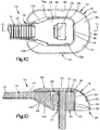
- an implant assembly 310 can include an implant, illustrated as a bone fixation element, such as a pedicle screw and fixation rod system 314 that is configured to be coupled to at least one vertebra and a cap 318 is configured to be coupled to the system 314.
- the system 314 is configured to secure first and second bone parts such as a first and second vertebra.
- the system 314 can include a pedicle screw 326 and a spinal fixation rod 325 that is secured to the pedicle screw 326.
- the spinal fixation rod 325 can define an inner surface 324 such as a bone facing surface and an opposed outer surface 321.
- the pedicle screw 326 can include a head portion 323 that defines a rod receiving channel, an engagement portion that extends from the head portion 323 and is configured to attach to bone, and a set screw 327 configured to couple to the head portion 323 so as to secure the spinal fixation rod 325 within the rod receiving channel.
- the head portion 323 and/or the set screw 327 can define at least one unsmooth surface 330. Therefore, it can be said that the pedicle screw and bone fixation rod are an implant body that defines at least one unsmooth surface 330. It should be appreciated, that while the spinal fixation rod 325 defines a bone facing surface that the pedicle screw can also define a bone facing surface of the system 314.
- the cap 318 can be configured to be coupled to the system 314 and in particular to the head portion 323 of the pedicle screw 326 and/or to the spinal fixation rod 325, such that the cap 318 overlies the system 326 or at least the unsmooth surface 330 to thereby eliminate the unsmooth surface and/or reduce the palpability of the system 326. Therefore, the cap 318 can be configured to remove sharp edges from and/or reduce the palpability of the system 326 when coupled to the system 326. As shown in Fig. 3A the cap 318 includes a cap body 334 that is curved or otherwise rounded so as to reduce irritation that may be caused to the surrounding soft tissue by the system 326.
- the cap body 334 defines a first or upper end 338 and a second or lower end 342 that is spaced from the first end 338 along the transverse direction.
- the cap body 334 further includes a cavity 346 that extends into the lower end 342.
- the cavity 346 is configured to receive at least a portion of the system 326 such as at least a portion of the head portion 323 and/or the spinal fixation rod 325.
- the first end 338 of the cap body 334 defines an upper surface 350 that is curved, or otherwise rounded and includes a distal body end 364 and a proximal body end 368 spaced from the distal body end 364 along the longitudinal direction L.
- the cap body 334 can be curved or otherwise dome shaped so as to define a convex outer surface 350.
- the upper surface 350 is curved such that the slope of the upper surface 350 increases as the upper surface 350 extends outward from a centerline of the upper surface 350.
- the cap body 334 can define an outer shell 380 that includes a ceiling 370 and at least one side wall 374 that extends down from the first end and defines at least a first inner surface 375a and a second inner surface 375b that is spaced from and substantially faces the first inner surface 375a along a first direction (e.g. the lateral direction) such that the ceiling 370 and the first and second inner surfaces 375a and 375b at least partially define the cavity 346.
- the outer shell 380 includes a continuous side wall 374 that is cylindrically shaped such that the first and second inner surfaces 375a and 375b are continuous with each other so as to be a single surface.
- the distal end of the cap body 334 defines a first opening 378a that extends into the cavity 346 and the proximal end of the cap body 334 defines a second opening 378b that extends into the cavity 346.
- the cavity 346 and the first and second openings 378a and 378b together define a channel 379 that extends through the cap body 334 along a second direction (e.g. the longitudinal direction) that is substantially perpendicular to the first direction.
- the channel 379 is substantially cylindrically shaped and is configured to receive the spinal fixation rod 325 so as to cover a portion of the spinal fixation rod 325 and at least a portion of the head portion 323 of the pedicle screw 326 and the openings 378a and 378b are configured to allow the spinal fixation rod 325 to extend through the openings 378a and 378b when the portion of the spinal rod 325 is received within the cavity 346 or channel 379. It should be appreciated, that while the side wall 374 is continuous, the side wall 374 can be segmented, as desired.
- the shell 380 is configured to elastically flex as the cavity 346 receives the head portion 323 and/or the rod 325. That is, the side wall 374 is configured to elastically flex outwardly between a first position and a second position as the cavity 346 receives the head portion 323 and/or the rod 325.
- the cap 318 can further include an attachment mechanism that is configured to couple the cap 318 to the system 314.
- the attachment mechanism includes at least one, such as a first and a second attachment member 400 that are configured to couple the cap 318 to the system.
- the attachment mechanism or each attachment member 400 can be defined by or otherwise extend from the at least one side wall substantially along the first direction.
- the first and second attachment members 400 extend toward each other into the cavity 346 and are opposed to each other along the first direction.
- the attachment members 400 can each define an abutment surface 404 that faces the ceiling 370 of the cavity 346 such that when the cap 318 is coupled to the system 314 the abutment surfaces 404 abut the bone facing surface(s) 324 of the spinal fixation rod 325 to thereby trap or otherwise secure the head portion 323 and spinal fixation rod 325 within the cavity 346.
- the attachment members can include other configurations.
- the attachment members 400 can define C-clips.
- the cap 318 can include features other than the attachment members 400 that are configured to couple the cap 318 to the system 314.
- the attachment mechanism can be respective surfaces of the side walls 374 such that the surfaces create a frictional fit with the system or the attachment mechanism can be a fixation member such as a needle.
- the first and second attachment members 400 can be configured to abut respective bone facing surfaces of the head portion 323.
- a pedicle screw may be attached to a vertebra and a spinal fixation rod mad be attached to the pedicle screw to thereby form a spine fixation system 314.
- the cap 318 can then be coupled to the pedicle screw and/or the spinal fixation rod to thereby smooth out the sharp edges of the pedicle screw.
- the cap 318 can be coupled to the system 314 such that the cap 318 overlies the head portion of the pedicle screw, for example as shown in Figs. 3B-3D .
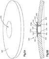
- an implant assembly 410 can include an implant, illustrated as a distractor, such as a palatal distractor 414 that is configured to be coupled to at least two bone parts and a cap 418 that is configured to be coupled to the distractor 414.
- the distractor 414 is configured to couple to first and second bone parts so that the bone parts can be moved away from each other using the distractor 414.
- the distractor 414 can be configured to expand an individual's maxilla. It should be appreciated, however, that the distractor 414 can be configured to expand any bone as desired.
- the distractor 414 can include a distractor body 426, a first coupling member 425a that extends from a first end of the distractor body 426 and a second coupling member 425b that extends from a second opposed end of the distractor body 426.
- the first and second coupling members 425a and 425b are configured to be attached to respective bone parts.
- the distractor body 426 is configured to move at least one of the first and second coupling members 425a and 425b away from the other so as to cause at least one of the bone parts to move away from the other.
- the distractor body 426 can define an inner surface 424 such as a tissue facing surface and an opposed outer surface 425.
- the distractor body 426 can further define at least one unsmooth surface 430.
- the cap 418 can be configured to be coupled to the distractor 414 and in particular to the distractor body 426, such that the cap 418 overlies the distractor body 426 or at least the unsmooth surface 430 to thereby eliminate the unsmooth surface and/or reduce the palpability of the distractor body 426. Therefore, the cap 418 can be configured to remove sharp edges from and/or reduce the palpability of the distractor body 426 when coupled to the distractor body 426. As shown in Figs. 4A and 4B the cap 418 includes a cap body 434 that is curved or otherwise rounded so as to reduce irritation that may be caused to the surrounding soft tissue (e.g. a tongue) by the distractor body 426.
- the cap body 434 defines a first or upper end 438 and a second or lower end 442 that is spaced from the first end 438 along the transverse direction.
- the cap body 434 further includes a cavity 446 that extends into the lower end 442.
- the cavity 446 is configured to receive at least a portion of the distractor body 426.
- the first end 438 of the cap body 434 defines an upper surface 450 that is curved, or otherwise rounded and includes a distal body end 464 and a proximal body end 468 spaced from the distal body end 464 along the longitudinal direction L.
- the cap body 434 can be curved or otherwise rounded along the lateral direction so as to define a convex outer surface 450.
- the upper surface 450 is curved such that the slope of the upper surface 450 increases as the upper surface 450 extends outward from a centerline of the upper surface 450.
- the cap body 434 can define an outer shell 480 that includes a ceiling 470 and at least one side wall 474 that extends from the first end 438 and defines at least a first inner surface 475a and a second inner surface 475b that is spaced from and substantially faces the first inner surface 475a along a first direction (e.g. the lateral direction) such that the ceiling 470 and the first and second inner surfaces 475a and 475b at least partially define the cavity 446.
- the outer shell 480 includes first and second side walls 474 that are parallel to each other and opposed to each other along the first direction such that the first and second inner surfaces 475a and 475b are parallel to each other and opposed to each other along the first direction.
- the distal end of the cap body 434 defines a first opening 478a that extends into the cavity 446 and the proximal end of the cap body 434 defines a second opening 478b that extends into the cavity 446.
- the cavity 446 and the first and second openings 478a and 478b together define a channel 479 that extends through the cap body 434 along a second direction (e.g. the longitudinal direction) that is substantially perpendicular to the first direction.
- the channel 479 is substantially cylindrically shaped and is configured to receive the distractor body 426 so as to cover a portion of the distractor body 426 and the openings 478a and 478b are configured to allow the first and second coupling members 425a and 425b to extend through the openings 478a and 478b when the portion of the distractor body 426 is received within the cavity 446 or channel 479.
- the shell 480 is configured to elastically flex as the cavity 446 receives the distractor body 426. That is, the side walls 474 are configured to elastically flex outwardly between a first position and a second position as the cavity 446 receives the distractor body 426.
- the cap 418 can further include an attachment mechanism that is configured to couple the cap 418 to the distractor 414.
- the attachment mechanism includes at least one, such as first, second, third, and fourth attachment members 400 that are configured to couple the cap 418 to the distractor.
- the attachment mechanism or each attachment member 500 can be defined by or otherwise extend from the at least one side wall substantially along the first direction.
- the first and second, and the third and fourth attachment members 500 extend toward each other into the cavity 446 and are opposed to each other along the first direction.
- the attachment members 500 can each define an abutment surface 504 that faces the ceiling 470 of the cavity 446 such that when the cap 418 is coupled to the distractor 414 the abutment surfaces 504 abut the inner surface(s) 424 of the distractor body 426 to thereby trap or otherwise secure the distractor body 426 within the cavity 446.
- the attachment members can include other configurations.
- the attachment members 500 can define C-clips.
- the cap 418 can include features other than the attachment members 500 that are configured to couple the cap 418 to the distractor 414.
- the attachment mechanism can be respective surfaces of the side walls 474 such that the surfaces create a frictional fit with the system or the attachment mechanism can be a fixation member such as a needle.
- the first and second attachment members 500 can be configured to abut respective inner surfaces of the distractor body 426.
- a distractor 414 may be attached to a pair of palatal bone portions.
- the cap 418 can then be coupled to the distractor 414 to thereby smooth out the sharp edges of the distractor 414.
- the cap 418 can be coupled to the distractor 414 such that the cap 418 overlies the distractor body 426, for example as shown in Figs. 4B-4E .
- an implant assembly 510 can include a cap 518 that is configured to be coupled to an aperture 519 defined by an anatomical structure 520 such as a clamp member of a cranial clamp as illustrated.
- the cap 518 can be configured to be coupled to the implant 520 through an aperture 519, such that the cap 518 overlies the aperture 519 or at least an unsmooth surface of the implant 520 to thereby eliminate the unsmooth surface and/or reduce the palpability of the implant. Therefore, the cap 518 can be configured to remove sharp edges from and/or reduce the palpability of the implant when coupled to the implant. As shown in Fig.
- the cap 518 includes a cap body 534 that is curved or otherwise rounded so as to correspond to the curved surface of the implant 520 and thereby reduce irritation that may be caused to the surrounding soft tissue by the implant 520.
- the cap body 534 defines a first or upper end 538 and a second or lower end 542 that is spaced from the first end 538 along the transverse direction.
- the cap 518 can be further configured to couple to an aperture defined by a bone such that the cap 518 overlies the bone when coupled to the bone.
- cap 518 can be configured to engage an aperture defined by the bone to thereby couple the cap 518 to the bone.
- the first end 538 of the cap body 534 defines an upper surface 550 that is curved, or otherwise rounded so as to define a convex outer surface 550.
- the cap body 534 can define an outer shell 580 and an inner shell 584 disposed within the outer shell 580.
- the outer shell 584 includes a ceiling 570 that substantially corresponds to the outer surface of the implant 520 and the inner shell 584 includes at least one side wall 574 that define at least a first inner surface 575a and a second inner surface 575b that is spaced from and substantially faces the first inner surface 575a along a first direction (e.g. the lateral direction).
- the inner shell 584 can further define an outer surface 596.
- the inner shell 584 is configured to elastically flex relative to the outer shell 580 when the inner shell 584 is received by the aperture 519. That is, the at least one side wall 574b of the inner shell 584 is configured to elastically flex inwardly between a first position and a second position as the inner shell 584 is received by the aperture 519. It should be appreciated, however, that the inner shell 584 can be configured to be non-flexible, as desired.
- the inner shell 584 or at least the at least one side wall 574 can be configured to be inserted through one of the apertures of the implant 520 or into the aperture of the bone.
- the at least one side wall 574 is substantially continuous and is substantially cylindrical in shape. It should be appreciated, however, that the at least one side wall 574 is discontinuous and/or has a different shape as desired, so long as the inner shell 584 can be passed through a aperture in the implant or bone.
- the cap 518 can further include an attachment mechanism that is configured to couple the cap 518 to the implant or bone.
- the attachment mechanism includes at least one, such as a first and a second attachment member 600 that are configured to couple the cap 518 to the implant or bone.
- the attachment mechanism or attachment members 600 can be defined by or otherwise extend from the at least one side wall and can be substantially continuous as the attachment member extends around the side wall. Therefore, it can be said that at least a portion of the at least one attachment member 600 extends away from another at least a portion of the at least one attachment member 600 and the at least a portions of the attachment member 600 are opposed to each other along the first direction.
- the attachment member 600 can be configured to provide an interference fit with the implant 520 when the inner shell 584 is received by the aperture 519 as illustrated in Fig. 5B . It should be appreciated, however, that the attachment member 600 can be configured to define an abutment surface that is configured to abut an inner surface of the implant 520. Further it should be appreciated that the attachment mechanism can be an external surface of the side wall 574 such that the external surface creates a frictional fit with the bone or implant.
Landscapes
- Health & Medical Sciences (AREA)
- Orthopedic Medicine & Surgery (AREA)
- Life Sciences & Earth Sciences (AREA)
- Surgery (AREA)
- Veterinary Medicine (AREA)
- Public Health (AREA)
- General Health & Medical Sciences (AREA)
- Animal Behavior & Ethology (AREA)
- Engineering & Computer Science (AREA)
- Biomedical Technology (AREA)
- Neurology (AREA)
- Heart & Thoracic Surgery (AREA)
- Molecular Biology (AREA)
- Nuclear Medicine, Radiotherapy & Molecular Imaging (AREA)
- Medical Informatics (AREA)
- Oral & Maxillofacial Surgery (AREA)
- Dentistry (AREA)
- Epidemiology (AREA)
- Prostheses (AREA)
- Surgical Instruments (AREA)
- Transplantation (AREA)
- Cardiology (AREA)
- Vascular Medicine (AREA)
Claims (11)
- Implantatanordnung (10), umfassend:ein Implantat (14), eingerichtet an zumindest ein Knochenteil gekoppelt zu werden; undeine Kappe (18), eingerichtet an das Implantat (14) gekoppelt zu werden, sodass die Kappe (18) über zumindest einem Teil des Implantats (14) liegt, wobei die Kappe (18) eine Schale (80, 84) enthält, die eine Kavität (46) definiert, die eingerichtet ist, zumindest einen Teil des Implantats (14) aufzunehmen, sodass sich die Schale (80, 84) relativ zum Implantat (14) elastisch verbiegt, wenn die Kavität (46) den zumindest einen Teil des Implantats (14) aufnimmt, um dadurch die Kappe (18) an das Implantat (14) zu koppeln, und die Kappe (18) eine äußere Oberfläche (50) definiert, die gekrümmt ist,wobei das Implantat (14) ein Knochenfixierelement ist, das einen Verriegelungskopf (26) und einen Riemen (22) aufweist, der eingerichtet ist, durch den Verriegelungskopf (26) entlang einer Einführrichtung hindurchzutreten, um eine Schlinge zu bilden, wobei die Kavität (46) eingerichtet ist, zumindest einen Teil des Verriegelungskopfes (26) aufzunehmen, und die Kappe (18) eine erste Öffnung (78) definiert, die sich in die Kavität (46) hinein erstreckt, sodass sich ein Teil des Riemens (22) durch die Öffnung (78) hindurch erstreckt, wenn der zumindest eine Teil des Verriegelungskopfes (26) von der Kavität (46) aufgenommen ist.
- Implantatanordnung nach Anspruch 1, wobei die Schale (80, 84) eine innere Schale (84) und eine äußere Schale (80) enthält, wobei die innere Schale (84) die Kavität (46) definiert und die innere Schale (84) eingerichtet ist, sich relativ zum Implantat (14) und relativ zur äußeren Schale (80) zu verbiegen, wenn die Kavität (46) den zumindest einen Teil des Implantats (14) aufnimmt.
- Implantatanordnung nach Anspruch 1 oder 2, wobei die Schale (84) zumindest eine Seitenwand (74) enthält, wobei die zumindest eine Seitenwand (74) zumindest eine erste innere Oberfläche (75a) und eine zweite innere Oberfläche (75b), die von der ersten inneren Oberfläche (75a) entlang einer ersten Richtung beabstandet ist, sodass die zweite innere Oberfläche (75b) im Wesentlichen der ersten inneren Oberfläche (75a) zugewandt ist, definiert,
wobei die Implantatanordnung (10) des Weiteren einen durch die zumindest eine Seitenwand (74) definierten Befestigungsmechanismus umfasst, wobei der Befestigungsmechanismus eingerichtet ist, den zumindest einen Teil des Implantats (14) in der Kavität (46) zu halten, wenn die Kavität (46) den zumindest einen Teil des Implantats (14) aufnimmt, wobei der Befestigungsmechanismus ein erstes Befestigungsteil (100) und ein zweites Befestigungsteil (100) enthält, wobei sich das erste und zweite Befestigungsteil (100) jeweils von der zumindest einen Seitenwand (74) im Wesentlichen entlang der ersten Richtung erstrecken. - Implantatanordnung nach Anspruch 3, wobei das erste und zweite Befestigungsteil (100) eingerichtet sind, an entsprechenden knochenzugewandten Oberflächen (24) des Implantats (14) anzuliegen, wenn der zumindest eine Teil des Implantats (14) in der Kavität (46) gehalten wird.
- Implantatanordnung nach Anspruch 3, wobei das erste und zweite Befestigungsteil (100) entlang der ersten Richtung einander gegenüberliegen.
- Implantatanordnung nach einem der Ansprüche 3 bis 5, wobei sich das erste und zweite Befestigungsteil (100) im Wesentlichen entlang der ersten Richtung aufeinander zu erstrecken.
- Implantatanordnung nach einem der Ansprüche 3 bis 6, wobei die zumindest eine Seitenwand (74) eine dritte Oberfläche (75c) definiert, die die erste Oberfläche (75a) mit der zweiten Oberfläche (75b) verbindet, wobei die erste, zweite und dritte Oberfläche (75a-c) vorzugsweise kontinuierlich sind.
- Implantatanordnung nach einem der vorhergehenden Ansprüche, wobei die äußere Oberfläche (50) zumindest teilweise konvex ist.
- Implantatanordnung nach Anspruch 3, wobei die Schale (84) eine Decke (70) enthält, die teilweise die Kavität (46) definiert und jedes des ersten und zweiten Befestigungsteils (100) eine Anlageoberfläche (104) definiert, die zumindest teilweise der Decke (70) zugewandt ist.
- Implantatanordnung nach Anspruch 3, wobei die Kappe (18) einen Kappenkörper (34) enthält, und der Kappenkörper (34) eine erste Öffnung (78) definiert, die sich in die Kavität (46) hinein erstreckt, sodass sich ein Teil des Implantats (14) durch die Öffnung (78) hindurch erstreckt, wenn der zumindest eine Teil des Implantats (14) von der Kavität (46) aufgenommen ist.
- Implantatanordnung nach Anspruch 3, wobei die Kappe (18) einen Kappenkörper (34) enthält und der Kappenkörper (34) ein erstes Ende (38) und ein zweites Ende (42) enthält, wobei sich die Kavität (46) in das zweite Ende (42) hinein in Richtung des ersten Endes (38) erstreckt, wobei sich die zumindest eine Seitenwand (74) vom ersten Ende (38) erstreckt, sodass die zumindest eine Seitenwand (74) relativ zum ersten Ende (38) flexibel ist.
Applications Claiming Priority (3)
| Application Number | Priority Date | Filing Date | Title |
|---|---|---|---|
| US201361756758P | 2013-01-25 | 2013-01-25 | |
| US201361763672P | 2013-02-12 | 2013-02-12 | |
| PCT/US2014/012037 WO2014116516A2 (en) | 2013-01-25 | 2014-01-17 | Caps for implants, implant assemblies, and methods of use |
Publications (2)
| Publication Number | Publication Date |
|---|---|
| EP2948072A2 EP2948072A2 (de) | 2015-12-02 |
| EP2948072B1 true EP2948072B1 (de) | 2018-08-15 |
Family
ID=50070697
Family Applications (1)
| Application Number | Title | Priority Date | Filing Date |
|---|---|---|---|
| EP14703487.0A Not-in-force EP2948072B1 (de) | 2013-01-25 | 2014-01-17 | Deckel für implantate und implantatanordnungen |
Country Status (8)
| Country | Link |
|---|---|
| US (1) | US9474553B2 (de) |
| EP (1) | EP2948072B1 (de) |
| JP (1) | JP6339106B2 (de) |
| KR (1) | KR102127101B1 (de) |
| CN (1) | CN105101893B (de) |
| BR (1) | BR112015017626A2 (de) |
| CA (1) | CA2899167C (de) |
| WO (1) | WO2014116516A2 (de) |
Families Citing this family (13)
| Publication number | Priority date | Publication date | Assignee | Title |
|---|---|---|---|---|
| US20160287299A1 (en) * | 2012-07-14 | 2016-10-06 | Aubrey Group, Inc. | Bone fixation device and method |
| US9597132B2 (en) | 2013-01-12 | 2017-03-21 | Louis Houff | Sternum fixation device and method |
| US10433889B2 (en) | 2013-07-11 | 2019-10-08 | Stryker European Holdings I, Llc | Fixation assembly with a flexible elongated member for securing parts of a sternum |
| SE538496C2 (en) * | 2014-07-11 | 2016-08-09 | Resorbable Devices Ab | Cable tie based medical device |
| EP3042622B1 (de) | 2015-01-09 | 2018-05-09 | Stryker European Holdings I, LLC | Implantat zur Knochenfixierung |
| US12262917B2 (en) | 2016-05-19 | 2025-04-01 | Auctus Surgical, Inc. | Spinal curvature modulation systems and methods |
| CA3023593A1 (en) * | 2016-05-19 | 2017-11-23 | Auctus Surgical, Llc | Spinal curvature modulation systems |
| EP3320868B1 (de) * | 2016-11-11 | 2019-05-01 | Stryker European Holdings I, LLC | Implantat zur knochenfixierung |
| DE102017101659A1 (de) * | 2017-01-27 | 2018-08-02 | Technische Universität Dresden | Distraktor, insbesondere Oberkiefer-Distraktor |
| US11793508B2 (en) | 2019-09-28 | 2023-10-24 | Tas Medical, Inc. | Systems, devices and methods for tissue fixation and approximating tissue defects |
| US12290295B2 (en) | 2020-06-19 | 2025-05-06 | Circumfix Solutions, Inc. | Bone repair devices and methods |
| AU2022320691A1 (en) | 2021-07-29 | 2024-02-15 | Circumfix Solutions, Inc. | Bone repair devices and methods |
| CN115005956A (zh) * | 2022-05-19 | 2022-09-06 | 江苏百易得医疗科技有限公司 | 一种胸骨板装置 |
Family Cites Families (95)
| Publication number | Priority date | Publication date | Assignee | Title |
|---|---|---|---|---|
| US2987062A (en) | 1956-07-23 | 1961-06-06 | Arthur E Ellison | Bone splint with absorbable section |
| US3570497A (en) | 1969-01-16 | 1971-03-16 | Gerald M Lemole | Suture apparatus and methods |
| US3577601A (en) | 1969-03-12 | 1971-05-04 | Thomas & Betts Corp | Article fastening device |
| US3835860A (en) | 1973-06-21 | 1974-09-17 | H Garretson | Surgical bone punch |
| US3910282A (en) | 1974-05-22 | 1975-10-07 | American Cyanamid Co | Needling monofilament sutures |
| US4037603A (en) | 1975-05-13 | 1977-07-26 | Wendorff Erwin R | Metallic surgical suture |
| GB1552677A (en) | 1976-07-06 | 1979-09-19 | Chichester Partridge Ltd | Tie for use in surgery |
| US4138770A (en) | 1977-04-22 | 1979-02-13 | Electro-Ty, Inc. | Bundling tie |
| EP0009327A1 (de) | 1978-09-01 | 1980-04-02 | Herbert D. Huddleston | Hüftnagel und Verfahren zu seiner Verwendung |
| DE3244680C2 (de) | 1982-12-02 | 1984-10-18 | Peter Dr. 8445 Schwarzach Clarenz | Vorrichtung zum Zusammenhalten der Teile eines gebrochenen Knochens |
| US4535764A (en) | 1983-04-15 | 1985-08-20 | Tayco Developments, Inc. | Surgical bone tie |
| US4955913A (en) | 1985-03-28 | 1990-09-11 | Robinson Walter C | Surgical tie |
| DE3517204A1 (de) | 1985-05-13 | 1986-11-13 | Gerald Dr. 8000 München Hauer | Dauerspannbares kunststoffband mit selbsthalterung |
| DE3538645A1 (de) | 1985-10-30 | 1987-05-07 | Gundolf Ferdinand | Vorrichtung zur osteosynthese von knochenfragmenten, insbesondere zur fixation von knochenfrakturen |
| US4730615A (en) | 1986-03-03 | 1988-03-15 | Pfizer Hospital Products Group, Inc. | Sternum closure device |
| AU1684788A (en) | 1987-02-20 | 1988-09-14 | Edward M. Farrell | Surgical tying devices |
| US4813416A (en) | 1987-03-18 | 1989-03-21 | The Research Foundation Of State University Of New York | Bonding assembly and method for sternum closing |
| DE8709487U1 (de) | 1987-07-09 | 1987-10-15 | Paul Hellermann Gmbh, 2080 Pinneberg | Werkzeug zum Spannen und Abschneiden eines Haltebandes |
| US4950269A (en) * | 1988-06-13 | 1990-08-21 | Acromed Corporation | Spinal column fixation device |
| US4901721A (en) | 1988-08-02 | 1990-02-20 | Hakki Samir I | Suturing device |
| DE4021246A1 (de) | 1990-07-04 | 1992-01-09 | Gundolf Ferdinand | Vorrichtung zur osteosynthese von knochenfragmenten, insbesondere zur fixation von knochenfrakturen |
| DE4024334A1 (de) | 1990-07-31 | 1992-02-06 | Gundolf Ferdinand | Vorrichtung zur osteosynthese von knochenfragmenten, insbesondere zur fixation von knochenfrakturen |
| DE4200757A1 (de) | 1991-01-14 | 1992-07-16 | Gundolf Ferdinand | Vorrichtung zur osteosynthese von knochenfragmenten, insbesondere zur fixation von knochenfrakturen |
| US5146645A (en) | 1991-03-01 | 1992-09-15 | The Procter & Gamble Company | Toothbrush employing resiliently buckling arch to indicate excessive brushing pressure |
| US5146654A (en) | 1991-05-03 | 1992-09-15 | Panduit Corp. | Stretched cable tie |
| GB9111972D0 (en) | 1991-06-04 | 1991-07-24 | Clinical Product Dev Ltd | Medical/surgical devices |
| KR930004380Y1 (ko) | 1991-06-14 | 1993-07-14 | 조우신 | 골유합술용 내고정금속판 |
| DE4127550A1 (de) | 1991-08-20 | 1993-02-25 | Telos Herstellung Und Vertrieb | Implantierbare verbindungsplatte zum befestigen eines elastischen flachbandes an einem knochen |
| US5193250A (en) | 1992-04-30 | 1993-03-16 | Panduit Corp. | Releasable cable tie |
| US5318566A (en) | 1992-06-22 | 1994-06-07 | Danek Medical, Inc. | Sternotomy cable and method |
| DE4228909C2 (de) | 1992-08-28 | 1994-06-09 | Ethicon Gmbh | Endoskopisches Instrument zur Applizierung von Ligaturbindern und Ligaturbinder |
| US5355913A (en) | 1992-10-09 | 1994-10-18 | United States Surgical Corporation | Surgical repair device |
| US5356417A (en) | 1992-10-09 | 1994-10-18 | United States Surgical Corporation | Absorbable sternum closure buckle |
| US5403346A (en) | 1992-12-31 | 1995-04-04 | Loeser; Edward A. | Self-affixing suture assembly |
| US5366461A (en) | 1993-01-25 | 1994-11-22 | William Blasnik | Sternum banding assembly |
| CA2088119C (en) | 1993-01-26 | 1998-09-01 | William Blasnik | Sternum banding assembly |
| FR2702951B1 (fr) | 1993-03-26 | 1995-06-16 | Cremascoli France | Dispositif de cerclage d'os. |
| US5377388A (en) * | 1993-12-27 | 1995-01-03 | Decor Concepts, Inc. | Safety cap |
| US5462542A (en) | 1994-01-24 | 1995-10-31 | United States Surgical Corporation | Sternum buckle with serrated strap |
| AU1967095A (en) | 1994-02-17 | 1995-09-04 | Surgical Accessories, Inc. | Fastener and tensioner for bone securing cable |
| US5456246A (en) | 1994-02-23 | 1995-10-10 | Arthrex, Inc. | Fat pad retractor |
| US5636412A (en) | 1995-11-01 | 1997-06-10 | The Procter & Gamble Company | Fixed circumference binding device with non-protruding free end and method for binding therewith |
| FR2742649B1 (fr) | 1995-12-22 | 1998-04-10 | Robert Louis Boutet | Lien de cerclage a usage medical et son procede de pose |
| FR2750032B1 (fr) * | 1996-06-20 | 1999-04-23 | Khenifar Brahim | Broche d'osteosynthese |
| US5766218A (en) | 1996-10-01 | 1998-06-16 | Metamorphic Surgical Devices, Inc. | Surgical binding device and method of using same |
| US5972024A (en) | 1996-12-24 | 1999-10-26 | Metacardia, Inc. | Suture-staple apparatus and method |
| US5879371A (en) | 1997-01-09 | 1999-03-09 | Elective Vascular Interventions, Inc. | Ferruled loop surgical fasteners, instruments, and methods for minimally invasive vascular and endoscopic surgery |
| US5972006A (en) | 1997-01-28 | 1999-10-26 | Stony Brook Surgical Innovations, Inc. | Buckle securing means for sternum banding assembly |
| DE19716504A1 (de) | 1997-04-19 | 1998-12-03 | Hinze Manfred Dr Med Habil | Kompressionscerclage und Instrumentarium zum Befestigen derselben |
| EP0876798A3 (de) | 1997-05-05 | 2000-01-19 | Rainer Otto | Carclage-Spannvorrichtung für die Osteosynthese von Knochenfrakturen |
| DE19806628C2 (de) | 1998-02-18 | 2000-08-10 | Daimler Chrysler Aerospace | Kabelbinder für die Bündelung oder Befestigung von Leitungen |
| US6613059B2 (en) | 1999-03-01 | 2003-09-02 | Coalescent Surgical, Inc. | Tissue connector apparatus and methods |
| WO2002080789A1 (en) * | 2001-04-05 | 2002-10-17 | Osteotech, Inc. | Bone fixation system and method |
| US6589246B1 (en) | 2001-04-26 | 2003-07-08 | Poly-4 Medical, Inc. | Method of applying an active compressive force continuously across a fracture |
| US6489246B1 (en) | 2001-05-01 | 2002-12-03 | Eastman Kodak Company | Method for manufacturing charge-coupled image sensors |
| US20030153947A1 (en) | 2002-02-14 | 2003-08-14 | Tomoaki Koseki | Sternum suture material and its manufacturing method |
| US20030236538A1 (en) | 2002-06-19 | 2003-12-25 | Thomas Aikens | Artery and vein coupling tie string |
| US7164360B2 (en) | 2002-08-14 | 2007-01-16 | Mark Schiebler | Multi-use linkage device |
| JP2004113392A (ja) | 2002-09-25 | 2004-04-15 | Koseki Ika Kk | 胸骨縫合用バンド |
| JP2004113520A (ja) | 2002-09-26 | 2004-04-15 | Koseki Ika Kk | 針がインサート成型された手術用縫合材料 |
| JP4098137B2 (ja) | 2003-03-31 | 2008-06-11 | 小池 央 | 人間以外の哺乳類生体からの臓器摘出方法、および卵巣子宮摘出方法 |
| US8105327B2 (en) | 2003-03-31 | 2012-01-31 | Depuy Products, Inc. | Punch, implant and associated method |
| GB0308647D0 (en) | 2003-04-15 | 2003-05-21 | Qualiteam S A S | Suture band |
| US7648504B2 (en) | 2003-09-09 | 2010-01-19 | Bioretec Ltd | Bioabsorbable band system |
| US20050090827A1 (en) * | 2003-10-28 | 2005-04-28 | Tewodros Gedebou | Comprehensive tissue attachment system |
| US8182518B2 (en) * | 2003-12-22 | 2012-05-22 | Life Spine, Inc. | Static and dynamic cervical plates and cervical plate constructs |
| CA2876804C (en) | 2004-02-13 | 2016-08-30 | Thomas & Betts International, Inc. | Tension and anti-recoil mechanism for cable tie tool |
| GB2414936A (en) | 2004-06-09 | 2005-12-14 | Ravi Kumar Khetrapal | Fracture reduction apparatus |
| US7008429B2 (en) | 2004-06-23 | 2006-03-07 | Golobek Donald D | Bio-absorbable bone tie with convex head |
| US7717938B2 (en) * | 2004-08-27 | 2010-05-18 | Depuy Spine, Inc. | Dual rod cross connectors and inserter tools |
| WO2006062419A1 (en) | 2004-12-08 | 2006-06-15 | Enztec Limited | Securing means for surgical use |
| US7527641B2 (en) * | 2005-03-11 | 2009-05-05 | Synthes Usa, Llc | Translational hinged door plate system |
| BRMU8501134Y1 (pt) | 2005-06-06 | 2016-05-03 | João Bosco De Oliveira | aperfeiçoamento construtivo introduzido em braçadeiras metálicas de aplicação na área de medicina cirúrgica |
| WO2006136938A1 (en) | 2005-06-24 | 2006-12-28 | Malan De Villiers | Interspinous stabilisation device |
| US20070173934A1 (en) * | 2006-01-20 | 2007-07-26 | Sdgi Holdings, Inc. | Devices to protect features on an implant and methods of use |
| EP1813292A1 (de) | 2006-01-25 | 2007-08-01 | Inion Oy | Chirurgische Implantate und deren Herstellungsverfahren |
| FR2906704A1 (fr) | 2006-10-05 | 2008-04-11 | David Attia | Collier de serrage pour chirurgie orthopedique. |
| DE102006059395A1 (de) | 2006-12-08 | 2008-06-19 | Aesculap Ag & Co. Kg | Implantat und Implantatsystem |
| US20080249569A1 (en) * | 2007-04-03 | 2008-10-09 | Warsaw Orthopedic, Inc. | Implant Face Plates |
| WO2009013397A1 (fr) | 2007-07-25 | 2009-01-29 | Ros Guillen, Francisco | Dispositif de fixation vertébrale pour système de correction des courbures anormales du rachis |
| SE531907C2 (sv) | 2008-01-14 | 2009-09-08 | Odd Hoeglund | Anordning för vävnadsligering |
| US8439936B2 (en) | 2008-03-06 | 2013-05-14 | Zone 2 Surgical, Inc. | Device and method for tendon, ligament or soft tissue repair |
| US20090275945A1 (en) * | 2008-04-30 | 2009-11-05 | Exploramed Nc4, Inc. | Sheaths for extra-articular implantable systems |
| WO2009134424A2 (en) * | 2008-04-30 | 2009-11-05 | Moximed, Inc. | Sheaths for extra-articular implantable systems |
| KR101712560B1 (ko) | 2008-06-24 | 2017-03-06 | 바이오엑티브 써지컬, 아이엔씨. | 줄기 세포 또는 기타 생활성 물질이 혼입된 수술용 봉합사 |
| CN102105114B (zh) * | 2008-07-25 | 2014-08-06 | 信其思有限责任公司 | 微创手术用植入物和压挤系统 |
| WO2010041101A1 (en) | 2008-10-10 | 2010-04-15 | Universita Degli Studi Di Padova | Haemostatic device for surgical procedures and emergencies |
| WO2010108050A2 (en) | 2009-03-19 | 2010-09-23 | Figure 8 Surgical, Inc. | Systems and methods for sternum repair |
| US8460295B2 (en) | 2009-03-19 | 2013-06-11 | Figure 8 Surgical, Inc. | Systems and methods for sternum repair |
| US8333791B2 (en) | 2009-04-24 | 2012-12-18 | Warsaw Orthopedic, Inc. | Medical implant with tie configured to deliver a therapeutic substance |
| US20100292739A1 (en) * | 2009-05-15 | 2010-11-18 | Warsaw Orthopedic, Inc. | Bone Screws With Improved Locking Mechanisms |
| WO2010135057A1 (en) | 2009-05-20 | 2010-11-25 | Synthes Usa, Llc | Peri-prosthetic fixation implant and method |
| US20120041441A1 (en) * | 2010-08-10 | 2012-02-16 | Acute Innovations, Llc. | Cable tie system for stabilizing bone |
| US9084644B2 (en) | 2011-02-02 | 2015-07-21 | DePuy Synthes Products, Inc. | Bone fixation assembly |
| US8740949B2 (en) * | 2011-02-24 | 2014-06-03 | Spinal Elements, Inc. | Methods and apparatus for stabilizing bone |
-
2014
- 2014-01-17 CA CA2899167A patent/CA2899167C/en not_active Expired - Fee Related
- 2014-01-17 CN CN201480006076.3A patent/CN105101893B/zh not_active Expired - Fee Related
- 2014-01-17 BR BR112015017626A patent/BR112015017626A2/pt not_active Application Discontinuation
- 2014-01-17 EP EP14703487.0A patent/EP2948072B1/de not_active Not-in-force
- 2014-01-17 JP JP2015555196A patent/JP6339106B2/ja not_active Expired - Fee Related
- 2014-01-17 KR KR1020157022672A patent/KR102127101B1/ko not_active Expired - Fee Related
- 2014-01-17 WO PCT/US2014/012037 patent/WO2014116516A2/en not_active Ceased
- 2014-01-21 US US14/159,715 patent/US9474553B2/en active Active
Non-Patent Citations (1)
| Title |
|---|
| None * |
Also Published As
| Publication number | Publication date |
|---|---|
| CN105101893B (zh) | 2019-04-26 |
| US20140214096A1 (en) | 2014-07-31 |
| KR102127101B1 (ko) | 2020-06-29 |
| EP2948072A2 (de) | 2015-12-02 |
| WO2014116516A4 (en) | 2015-01-22 |
| BR112015017626A2 (pt) | 2017-07-11 |
| US9474553B2 (en) | 2016-10-25 |
| CN105101893A (zh) | 2015-11-25 |
| JP6339106B2 (ja) | 2018-06-06 |
| CA2899167A1 (en) | 2014-07-31 |
| KR20150113034A (ko) | 2015-10-07 |
| JP2016521136A (ja) | 2016-07-21 |
| CA2899167C (en) | 2021-08-31 |
| WO2014116516A2 (en) | 2014-07-31 |
| WO2014116516A3 (en) | 2014-11-27 |
Similar Documents
| Publication | Publication Date | Title |
|---|---|---|
| EP2948072B1 (de) | Deckel für implantate und implantatanordnungen | |
| US20250241697A1 (en) | Alignment guide apparatus, methods and systems | |
| EP3082633B1 (de) | Orthopädische knochenplatte und verriegelungslasche | |
| EP3585278B1 (de) | Anvisierungsinstrumente und systeme | |
| US8398637B2 (en) | Device and method for less invasive surgical stabilization of pelvic fractures | |
| CN107205760B (zh) | 垫圈板 | |
| JP5911474B2 (ja) | 不規則な形状の本体に穴をあけるためのガイド | |
| WO2015094409A1 (en) | Alignment guide apparatus, methods and systems | |
| JP2020199388A (ja) | 連接ロッド挿入体 | |
| EP3581131A1 (de) | Trochanterplatten | |
| EP3539492B1 (de) | Knochenplatten | |
| EP0517435A1 (de) | Intramedulläre Vorrichtung zur Osteosynthese | |
| JP2019533511A (ja) | 二方向固定鋼板及び骨幹固定システム | |
| US11617609B2 (en) | Percutaneous methods, systems, and devices for positioning a guide wire in a bone | |
| EP1819303B1 (de) | Implantierbare fixieranordnung zur lösbaren fixierung eines medizinprodukts | |
| KR102314563B1 (ko) | 의료용 플레이트 고정홀더 | |
| EP2938300B1 (de) | Orthopädische knochenplatte und verriegelungslasche | |
| US20200078064A1 (en) | Bone segment attachment system and method | |
| US10646695B1 (en) | Percutaneous methods, systems, and devices for positioning a guide wire in a bone | |
| GB2256802A (en) | Improvements in or relating to bone support |
Legal Events
| Date | Code | Title | Description |
|---|---|---|---|
| PUAI | Public reference made under article 153(3) epc to a published international application that has entered the european phase |
Free format text: ORIGINAL CODE: 0009012 |
|
| 17P | Request for examination filed |
Effective date: 20150729 |
|
| AK | Designated contracting states |
Kind code of ref document: A2 Designated state(s): AL AT BE BG CH CY CZ DE DK EE ES FI FR GB GR HR HU IE IS IT LI LT LU LV MC MK MT NL NO PL PT RO RS SE SI SK SM TR |
|
| AX | Request for extension of the european patent |
Extension state: BA ME |
|
| DAX | Request for extension of the european patent (deleted) | ||
| RIN1 | Information on inventor provided before grant (corrected) |
Inventor name: KOCH, RUDOLF |
|
| STAA | Information on the status of an ep patent application or granted ep patent |
Free format text: STATUS: EXAMINATION IS IN PROGRESS |
|
| 17Q | First examination report despatched |
Effective date: 20161102 |
|
| GRAP | Despatch of communication of intention to grant a patent |
Free format text: ORIGINAL CODE: EPIDOSNIGR1 |
|
| STAA | Information on the status of an ep patent application or granted ep patent |
Free format text: STATUS: GRANT OF PATENT IS INTENDED |
|
| INTG | Intention to grant announced |
Effective date: 20180306 |
|
| GRAS | Grant fee paid |
Free format text: ORIGINAL CODE: EPIDOSNIGR3 |
|
| GRAA | (expected) grant |
Free format text: ORIGINAL CODE: 0009210 |
|
| STAA | Information on the status of an ep patent application or granted ep patent |
Free format text: STATUS: THE PATENT HAS BEEN GRANTED |
|
| AK | Designated contracting states |
Kind code of ref document: B1 Designated state(s): AL AT BE BG CH CY CZ DE DK EE ES FI FR GB GR HR HU IE IS IT LI LT LU LV MC MK MT NL NO PL PT RO RS SE SI SK SM TR |
|
| REG | Reference to a national code |
Ref country code: CH Ref legal event code: EP Ref country code: GB Ref legal event code: FG4D Ref country code: AT Ref legal event code: REF Ref document number: 1028832 Country of ref document: AT Kind code of ref document: T Effective date: 20180815 |
|
| REG | Reference to a national code |
Ref country code: CH Ref legal event code: NV Representative=s name: E. BLUM AND CO. AG PATENT- UND MARKENANWAELTE , CH |
|
| REG | Reference to a national code |
Ref country code: IE Ref legal event code: FG4D |
|
| REG | Reference to a national code |
Ref country code: DE Ref legal event code: R096 Ref document number: 602014030375 Country of ref document: DE |
|
| REG | Reference to a national code |
Ref country code: NL Ref legal event code: MP Effective date: 20180815 |
|
| REG | Reference to a national code |
Ref country code: LT Ref legal event code: MG4D |
|
| REG | Reference to a national code |
Ref country code: AT Ref legal event code: MK05 Ref document number: 1028832 Country of ref document: AT Kind code of ref document: T Effective date: 20180815 |
|
| PG25 | Lapsed in a contracting state [announced via postgrant information from national office to epo] |
Ref country code: FI Free format text: LAPSE BECAUSE OF FAILURE TO SUBMIT A TRANSLATION OF THE DESCRIPTION OR TO PAY THE FEE WITHIN THE PRESCRIBED TIME-LIMIT Effective date: 20180815 Ref country code: RS Free format text: LAPSE BECAUSE OF FAILURE TO SUBMIT A TRANSLATION OF THE DESCRIPTION OR TO PAY THE FEE WITHIN THE PRESCRIBED TIME-LIMIT Effective date: 20180815 Ref country code: AT Free format text: LAPSE BECAUSE OF FAILURE TO SUBMIT A TRANSLATION OF THE DESCRIPTION OR TO PAY THE FEE WITHIN THE PRESCRIBED TIME-LIMIT Effective date: 20180815 Ref country code: IS Free format text: LAPSE BECAUSE OF FAILURE TO SUBMIT A TRANSLATION OF THE DESCRIPTION OR TO PAY THE FEE WITHIN THE PRESCRIBED TIME-LIMIT Effective date: 20181215 Ref country code: BG Free format text: LAPSE BECAUSE OF FAILURE TO SUBMIT A TRANSLATION OF THE DESCRIPTION OR TO PAY THE FEE WITHIN THE PRESCRIBED TIME-LIMIT Effective date: 20181115 Ref country code: SE Free format text: LAPSE BECAUSE OF FAILURE TO SUBMIT A TRANSLATION OF THE DESCRIPTION OR TO PAY THE FEE WITHIN THE PRESCRIBED TIME-LIMIT Effective date: 20180815 Ref country code: NO Free format text: LAPSE BECAUSE OF FAILURE TO SUBMIT A TRANSLATION OF THE DESCRIPTION OR TO PAY THE FEE WITHIN THE PRESCRIBED TIME-LIMIT Effective date: 20181115 Ref country code: GR Free format text: LAPSE BECAUSE OF FAILURE TO SUBMIT A TRANSLATION OF THE DESCRIPTION OR TO PAY THE FEE WITHIN THE PRESCRIBED TIME-LIMIT Effective date: 20181116 Ref country code: NL Free format text: LAPSE BECAUSE OF FAILURE TO SUBMIT A TRANSLATION OF THE DESCRIPTION OR TO PAY THE FEE WITHIN THE PRESCRIBED TIME-LIMIT Effective date: 20180815 Ref country code: LT Free format text: LAPSE BECAUSE OF FAILURE TO SUBMIT A TRANSLATION OF THE DESCRIPTION OR TO PAY THE FEE WITHIN THE PRESCRIBED TIME-LIMIT Effective date: 20180815 |
|
| PG25 | Lapsed in a contracting state [announced via postgrant information from national office to epo] |
Ref country code: AL Free format text: LAPSE BECAUSE OF FAILURE TO SUBMIT A TRANSLATION OF THE DESCRIPTION OR TO PAY THE FEE WITHIN THE PRESCRIBED TIME-LIMIT Effective date: 20180815 Ref country code: LV Free format text: LAPSE BECAUSE OF FAILURE TO SUBMIT A TRANSLATION OF THE DESCRIPTION OR TO PAY THE FEE WITHIN THE PRESCRIBED TIME-LIMIT Effective date: 20180815 Ref country code: HR Free format text: LAPSE BECAUSE OF FAILURE TO SUBMIT A TRANSLATION OF THE DESCRIPTION OR TO PAY THE FEE WITHIN THE PRESCRIBED TIME-LIMIT Effective date: 20180815 |
|
| PG25 | Lapsed in a contracting state [announced via postgrant information from national office to epo] |
Ref country code: ES Free format text: LAPSE BECAUSE OF FAILURE TO SUBMIT A TRANSLATION OF THE DESCRIPTION OR TO PAY THE FEE WITHIN THE PRESCRIBED TIME-LIMIT Effective date: 20180815 Ref country code: PL Free format text: LAPSE BECAUSE OF FAILURE TO SUBMIT A TRANSLATION OF THE DESCRIPTION OR TO PAY THE FEE WITHIN THE PRESCRIBED TIME-LIMIT Effective date: 20180815 Ref country code: CZ Free format text: LAPSE BECAUSE OF FAILURE TO SUBMIT A TRANSLATION OF THE DESCRIPTION OR TO PAY THE FEE WITHIN THE PRESCRIBED TIME-LIMIT Effective date: 20180815 Ref country code: RO Free format text: LAPSE BECAUSE OF FAILURE TO SUBMIT A TRANSLATION OF THE DESCRIPTION OR TO PAY THE FEE WITHIN THE PRESCRIBED TIME-LIMIT Effective date: 20180815 Ref country code: EE Free format text: LAPSE BECAUSE OF FAILURE TO SUBMIT A TRANSLATION OF THE DESCRIPTION OR TO PAY THE FEE WITHIN THE PRESCRIBED TIME-LIMIT Effective date: 20180815 |
|
| REG | Reference to a national code |
Ref country code: DE Ref legal event code: R097 Ref document number: 602014030375 Country of ref document: DE |
|
| PG25 | Lapsed in a contracting state [announced via postgrant information from national office to epo] |
Ref country code: DK Free format text: LAPSE BECAUSE OF FAILURE TO SUBMIT A TRANSLATION OF THE DESCRIPTION OR TO PAY THE FEE WITHIN THE PRESCRIBED TIME-LIMIT Effective date: 20180815 Ref country code: SM Free format text: LAPSE BECAUSE OF FAILURE TO SUBMIT A TRANSLATION OF THE DESCRIPTION OR TO PAY THE FEE WITHIN THE PRESCRIBED TIME-LIMIT Effective date: 20180815 Ref country code: SK Free format text: LAPSE BECAUSE OF FAILURE TO SUBMIT A TRANSLATION OF THE DESCRIPTION OR TO PAY THE FEE WITHIN THE PRESCRIBED TIME-LIMIT Effective date: 20180815 |
|
| PLBE | No opposition filed within time limit |
Free format text: ORIGINAL CODE: 0009261 |
|
| STAA | Information on the status of an ep patent application or granted ep patent |
Free format text: STATUS: NO OPPOSITION FILED WITHIN TIME LIMIT |
|
| 26N | No opposition filed |
Effective date: 20190516 |
|
| PG25 | Lapsed in a contracting state [announced via postgrant information from national office to epo] |
Ref country code: SI Free format text: LAPSE BECAUSE OF FAILURE TO SUBMIT A TRANSLATION OF THE DESCRIPTION OR TO PAY THE FEE WITHIN THE PRESCRIBED TIME-LIMIT Effective date: 20180815 Ref country code: MC Free format text: LAPSE BECAUSE OF FAILURE TO SUBMIT A TRANSLATION OF THE DESCRIPTION OR TO PAY THE FEE WITHIN THE PRESCRIBED TIME-LIMIT Effective date: 20180815 |
|
| PG25 | Lapsed in a contracting state [announced via postgrant information from national office to epo] |
Ref country code: LU Free format text: LAPSE BECAUSE OF NON-PAYMENT OF DUE FEES Effective date: 20190117 |
|
| REG | Reference to a national code |
Ref country code: BE Ref legal event code: MM Effective date: 20190131 |
|
| REG | Reference to a national code |
Ref country code: IE Ref legal event code: MM4A |
|
| PG25 | Lapsed in a contracting state [announced via postgrant information from national office to epo] |
Ref country code: BE Free format text: LAPSE BECAUSE OF NON-PAYMENT OF DUE FEES Effective date: 20190131 |
|
| PG25 | Lapsed in a contracting state [announced via postgrant information from national office to epo] |
Ref country code: IE Free format text: LAPSE BECAUSE OF NON-PAYMENT OF DUE FEES Effective date: 20190117 |
|
| PG25 | Lapsed in a contracting state [announced via postgrant information from national office to epo] |
Ref country code: TR Free format text: LAPSE BECAUSE OF FAILURE TO SUBMIT A TRANSLATION OF THE DESCRIPTION OR TO PAY THE FEE WITHIN THE PRESCRIBED TIME-LIMIT Effective date: 20180815 |
|
| PGFP | Annual fee paid to national office [announced via postgrant information from national office to epo] |
Ref country code: IT Payment date: 20200114 Year of fee payment: 7 |
|
| PG25 | Lapsed in a contracting state [announced via postgrant information from national office to epo] |
Ref country code: MT Free format text: LAPSE BECAUSE OF NON-PAYMENT OF DUE FEES Effective date: 20190117 Ref country code: PT Free format text: LAPSE BECAUSE OF FAILURE TO SUBMIT A TRANSLATION OF THE DESCRIPTION OR TO PAY THE FEE WITHIN THE PRESCRIBED TIME-LIMIT Effective date: 20181215 |
|
| PGFP | Annual fee paid to national office [announced via postgrant information from national office to epo] |
Ref country code: FR Payment date: 20201210 Year of fee payment: 8 |
|
| PGFP | Annual fee paid to national office [announced via postgrant information from national office to epo] |
Ref country code: CH Payment date: 20210113 Year of fee payment: 8 |
|
| PG25 | Lapsed in a contracting state [announced via postgrant information from national office to epo] |
Ref country code: CY Free format text: LAPSE BECAUSE OF FAILURE TO SUBMIT A TRANSLATION OF THE DESCRIPTION OR TO PAY THE FEE WITHIN THE PRESCRIBED TIME-LIMIT Effective date: 20180815 |
|
| PGFP | Annual fee paid to national office [announced via postgrant information from national office to epo] |
Ref country code: GB Payment date: 20210106 Year of fee payment: 8 Ref country code: DE Payment date: 20210105 Year of fee payment: 8 |
|
| PG25 | Lapsed in a contracting state [announced via postgrant information from national office to epo] |
Ref country code: HU Free format text: LAPSE BECAUSE OF FAILURE TO SUBMIT A TRANSLATION OF THE DESCRIPTION OR TO PAY THE FEE WITHIN THE PRESCRIBED TIME-LIMIT; INVALID AB INITIO Effective date: 20140117 |
|
| PG25 | Lapsed in a contracting state [announced via postgrant information from national office to epo] |
Ref country code: IT Free format text: LAPSE BECAUSE OF NON-PAYMENT OF DUE FEES Effective date: 20210117 |
|
| PG25 | Lapsed in a contracting state [announced via postgrant information from national office to epo] |
Ref country code: MK Free format text: LAPSE BECAUSE OF FAILURE TO SUBMIT A TRANSLATION OF THE DESCRIPTION OR TO PAY THE FEE WITHIN THE PRESCRIBED TIME-LIMIT Effective date: 20180815 |
|
| REG | Reference to a national code |
Ref country code: DE Ref legal event code: R119 Ref document number: 602014030375 Country of ref document: DE |
|
| REG | Reference to a national code |
Ref country code: CH Ref legal event code: PL |
|
| GBPC | Gb: european patent ceased through non-payment of renewal fee |
Effective date: 20220117 |
|
| PG25 | Lapsed in a contracting state [announced via postgrant information from national office to epo] |
Ref country code: GB Free format text: LAPSE BECAUSE OF NON-PAYMENT OF DUE FEES Effective date: 20220117 Ref country code: DE Free format text: LAPSE BECAUSE OF NON-PAYMENT OF DUE FEES Effective date: 20220802 |
|
| PG25 | Lapsed in a contracting state [announced via postgrant information from national office to epo] |
Ref country code: FR Free format text: LAPSE BECAUSE OF NON-PAYMENT OF DUE FEES Effective date: 20220131 |
|
| PG25 | Lapsed in a contracting state [announced via postgrant information from national office to epo] |
Ref country code: LI Free format text: LAPSE BECAUSE OF NON-PAYMENT OF DUE FEES Effective date: 20220131 Ref country code: CH Free format text: LAPSE BECAUSE OF NON-PAYMENT OF DUE FEES Effective date: 20220131 |