EP2947732B1 - Herstellungsverfahren einer zündkerze - Google Patents
Herstellungsverfahren einer zündkerze Download PDFInfo
- Publication number
- EP2947732B1 EP2947732B1 EP15168638.3A EP15168638A EP2947732B1 EP 2947732 B1 EP2947732 B1 EP 2947732B1 EP 15168638 A EP15168638 A EP 15168638A EP 2947732 B1 EP2947732 B1 EP 2947732B1
- Authority
- EP
- European Patent Office
- Prior art keywords
- metal shell
- spark plug
- inner peripheral
- peripheral surface
- manufacturing
- Prior art date
- Legal status (The legal status is an assumption and is not a legal conclusion. Google has not performed a legal analysis and makes no representation as to the accuracy of the status listed.)
- Active
Links
- 238000004519 manufacturing process Methods 0.000 title claims description 35
- 239000002184 metal Substances 0.000 claims description 145
- 229910052751 metal Inorganic materials 0.000 claims description 145
- 238000000034 method Methods 0.000 claims description 102
- 238000003466 welding Methods 0.000 claims description 95
- 230000002093 peripheral effect Effects 0.000 claims description 62
- 239000012212 insulator Substances 0.000 claims description 34
- 239000000919 ceramic Substances 0.000 claims description 7
- 239000000835 fiber Substances 0.000 claims description 5
- 238000002485 combustion reaction Methods 0.000 description 12
- 238000012986 modification Methods 0.000 description 12
- 230000004048 modification Effects 0.000 description 12
- 238000002788 crimping Methods 0.000 description 8
- PXHVJJICTQNCMI-UHFFFAOYSA-N Nickel Chemical group [Ni] PXHVJJICTQNCMI-UHFFFAOYSA-N 0.000 description 6
- 238000011156 evaluation Methods 0.000 description 5
- 239000000463 material Substances 0.000 description 5
- 238000005520 cutting process Methods 0.000 description 4
- 238000007747 plating Methods 0.000 description 4
- 238000010008 shearing Methods 0.000 description 4
- 238000012360 testing method Methods 0.000 description 4
- PNEYBMLMFCGWSK-UHFFFAOYSA-N aluminium oxide Inorganic materials [O-2].[O-2].[O-2].[Al+3].[Al+3] PNEYBMLMFCGWSK-UHFFFAOYSA-N 0.000 description 3
- 229910000990 Ni alloy Inorganic materials 0.000 description 2
- 238000010292 electrical insulation Methods 0.000 description 2
- 229910052759 nickel Inorganic materials 0.000 description 2
- 239000000843 powder Substances 0.000 description 2
- 238000003825 pressing Methods 0.000 description 2
- 230000002265 prevention Effects 0.000 description 2
- 229910000975 Carbon steel Inorganic materials 0.000 description 1
- VYPSYNLAJGMNEJ-UHFFFAOYSA-N Silicium dioxide Chemical compound O=[Si]=O VYPSYNLAJGMNEJ-UHFFFAOYSA-N 0.000 description 1
- 238000005452 bending Methods 0.000 description 1
- 239000011230 binding agent Substances 0.000 description 1
- 239000010962 carbon steel Substances 0.000 description 1
- 229910010293 ceramic material Inorganic materials 0.000 description 1
- 229910052593 corundum Inorganic materials 0.000 description 1
- 230000000881 depressing effect Effects 0.000 description 1
- 238000005553 drilling Methods 0.000 description 1
- 238000010304 firing Methods 0.000 description 1
- 238000000227 grinding Methods 0.000 description 1
- 229910001026 inconel Inorganic materials 0.000 description 1
- 229910001055 inconels 600 Inorganic materials 0.000 description 1
- 229910010272 inorganic material Inorganic materials 0.000 description 1
- 239000011147 inorganic material Substances 0.000 description 1
- 238000009413 insulation Methods 0.000 description 1
- 238000003801 milling Methods 0.000 description 1
- 239000011368 organic material Substances 0.000 description 1
- 238000012545 processing Methods 0.000 description 1
- 238000004080 punching Methods 0.000 description 1
- 229910001845 yogo sapphire Inorganic materials 0.000 description 1
Images





Classifications
-
- H—ELECTRICITY
- H01—ELECTRIC ELEMENTS
- H01T—SPARK GAPS; OVERVOLTAGE ARRESTERS USING SPARK GAPS; SPARKING PLUGS; CORONA DEVICES; GENERATING IONS TO BE INTRODUCED INTO NON-ENCLOSED GASES
- H01T21/00—Apparatus or processes specially adapted for the manufacture or maintenance of spark gaps or sparking plugs
- H01T21/02—Apparatus or processes specially adapted for the manufacture or maintenance of spark gaps or sparking plugs of sparking plugs
Definitions
- aspects of the present invention relate to a manufacturing method of a spark plug.
- a spark plug in general, includes a center electrode, an insulator, a metal shell, and a ground electrode.
- the metal shell of the spark plug has a tubular shape having an end surface and an inner peripheral surface. The end surface of the metal shell is connected to the ground electrode.
- a gap for preventing spark leak (lateral spark) is formed between the inner peripheral surface of the metal shell and the insulator holding the center electrode. Spark leak is a phenomenon in which spark discharge is generated at a portion different from a spark gap between the center electrode and the ground electrode.
- JP-A-2003-223968 and JP-A-2011-175985 disclose techniques in which the end surface and the inner peripheral surface are formed to the metal shell and then the ground electrode is welded to the end surface of the metal shell.
- welding sag may protrude to the inside of the metal shell and such welding sag becomes a cause of the spark leak.
- JP-A-2003-223968 discloses the preamble of claim 1 and a technique in which the ground electrode is welded to the end surface of the metal shell and then the welding sag protruding to the inside of the metal shell is removed by a shearing process or a cutting process.
- the invention can be realized by various forms other than the spark plug and the manufacturing method of the spark plug.
- the invention can be realized in a form of a metal shell to which a ground electrode is welded, an internal combustion engine including a spark plug, and a manufacturing apparatus of a spark plug.
- Fig. 1 is an explanatory view illustrating a cross section of a portion of a spark plug 10.
- Fig. 1 illustrates an external shape of a spark plug 10 on a right side of the sheet and a cross section shape of the spark plug 10 on a left side of the sheet.
- An axial line CA1 which is an axis of the spark plug 10, serves as a boundary between the left side of the sheet and the right side of the sheet.
- a lower side of the sheet of Fig. 1 is referred to as a "leading end side” and an upper side of the sheet of Fig. 1 is referred to as a "rear end side" of the spark plug 10.
- the spark plug 10 includes a center electrode 100, an insulator 200, the metal shell 300, and a ground electrode 400.
- the axial line CA1 of the spark plug 10 is also an axis of each of the center electrode 100, the insulator 200, and the metal shell 300.
- the spark plug 10 has a gap SG formed between the center electrode 100 and the ground electrode 400 oat the leading end side thereof.
- the gap SG of the spark plug 10 is also referred to as a spark gap.
- the spark plug 10 is configured to be mountable to an internal combustion engine 90 in a state where the leading end side, to which the gap SG is formed, protrudes from an inner wall 910 of a combustion chamber 920. If a high voltage of 20000 volts to 30000 volts is applied to the center electrode 100 in a state where the spark plug 10 is mounted on the internal combustion engine 90, spark discharge is generated at the gap SG. The spark discharge generated at the gap SG realizes ignition to mixed air in the combustion chamber 920.
- Fig. 1 illustrates XYZ axes which are perpendicular to each other.
- the XYZ axes of Fig. 1 correspond to XYZ axes in other views described hereinafter.
- An X axis among the XYZ axes of Fig. 1 is an axis perpendicular to a Y axis and a Z axis.
- a +X axis direction is a direction from a back of the sheet to a front of the sheet of Fig. 1
- a -X axis direction is an opposite direction with respect to the +X axis direction.
- a +Y axis direction is a direction from a right of the sheet to a left of the sheet of Fig. 1 and a -Y axis direction is an opposite direction with respect to the +Y axis direction.
- the Z axis among the XYZ axes of Fig. 1 is an axis perpendicular to the X axis and the Y axis.
- a +Z axis direction is a direction from the rear end side to the leading end side of the spark plug 10 and a -Z axis direction is an opposite direction with respect to the +Z axis direction.
- the center electrode 100 of the spark plug 10 is an electrode having electrical conductivity.
- the center electrode 100 has a rod shape extending about the axial line CA1.
- a material of the center electrode 100 is formed of nickel alloy of which a main component is nickel (Ni) (for example, INCONEL 600 ("INCONEL" is a registered trade mark)).
- Ni nickel
- An external surface of the center electrode 100 is electrically insulated from outside by the insulator 200.
- the leading end of the center electrode 100 protrudes from the leading end side of the insulator 200.
- the rear end of the center electrode 100 is electrically connected to the rear end of the insulator 200.
- the rear end of the center electrode 100 is electrically connected to the rear end of the insulator 200 through a seal body 160, a ceramic resistance 170, a seal body 180, and a terminal shell 190.
- the ground electrode 400 of the spark plug 10 is an electrode having electrical conductivity.
- the ground electrode 400 has a shape that extends from the metal shell 300 in the +Z axis direction and then bends toward the axial line CA1.
- a rear end side of the ground electrode 400 is welded to the metal shell 300.
- a leading end side of the ground electrode 400 forms the gap SG between itself and the center electrode 100.
- a material of the ground electrode 400 is formed of nickel alloy of which a main component is nickel (Ni).
- the insulator 200 of the spark plug 10 is an insulator having electrical insulation property.
- the insulator 200 has a tubular shape extending along the axial line CA1.
- the insulator 200 is manufactured by firing an insulation ceramic material (for example, alumina).
- the insulator 200 has an axial hole 290 that is a through hole extending about the axial line CA1.
- the center electrode 100 is held on the axial line CA1 in the axial hole 290 of the insulator 200 in a state of protruding from the leading end side of the insulator 200.
- a first tubular portion 210, a second tubular portion 220, a third tubular portion 250, and a fourth tubular portion 270 are formed on the outside of the insulator 200 in this order from the leading end side to the rear end side.
- the first tubular portion 210 of the insulator 200 is a cylindrical portion tapered toward the leading end side and a leading end of the first tubular portion 210 protrudes from the leading end side of the metal shell 300.
- the second tubular portion 220 of the insulator 200 is a cylindrical portion having a diameter greater than that of the first tubular portion 210.
- the third tubular portion 250 of the insulator 200 is a cylindrical portion extending in an outer peripheral direction further than the second tubular portion 220 and the fourth tubular portion 270.
- the fourth tubular portion 270 of the insulator 200 is a cylindrical portion form to a rear side of the third tubular portion 250 and a rear end of the fourth tubular portion 270 protrudes from the rear end of the metal shell 300.
- the metal shell 300 of the spark plug 10 is a metallic body having electrical conductivity.
- the metal shell 300 has a tubular shape extending about the axial line CA1.
- a material of the metal shell 300 is carbon steel and nickel-plating is applied to a surface of the metal shell 300.
- zinc-plating may be applied to the surface of the metal shell 300 or plating may not be applied to the surface of the metal shell 300.
- the metal shell 300 is fixed to an outer surface of the insulator 200 by crimping in a state of being insulated from the center electrode 100.
- An end surface 310, a screw portion 320, a body portion 340, a groove portion 350, a tool engagement portion 360, and a crimping cover 380 are formed on the outside of the metal shell 300 in this order from the leading end side to the rear end side.
- the end surface 310 of the metal shell 300 is a surface configuring the leading end of the metal shell 300.
- the end surface 310 is a plane along the X axis and the Y axis, and is a plane facing the +Z axis direction.
- the end surface 310 is a hollow disk-shaped plane.
- the ground electrode 400 is welded to the end surface 310.
- the insulator 200 protrudes in the +Z axis direction together with the center electrode 100 from a center of the end surface 310.
- the end surface 310 may be a surface inclined to the inside of the metal shell 300 or may be a surface inclined to the outside the metal shell 300.
- the end surface 310 may be a curved surface or a plurality of surfaces configuring steps.
- the screw portion 320 of the metal shell 300 is a cylindrical portion where screw threads are formed on an outer surface thereof.
- the spark plug 10 is configured to be mountable on the internal combustion engine 90 by engaging the screw portion 320 of the metal shell 300 with a screw hole 930 of the internal combustion engine 90.
- a nominal diameter of the screw portion 320 is M10.
- the nominal diameter of the screw portion 320 may be smaller than M10 (for example, M8) or may be greater than M10 (for example, M12, M14).
- the body portion 340 of the metal shell 300 is a flange-shaped portion extending in an outer peripheral direction further than the groove portion 350. If the spark plug 10 is mounted on the internal combustion engine 90, a gasket 500 is compressed between the body portion 340 and the internal combustion engine 90.
- the groove portion 350 of the metal shell 300 is a cylindrical portion expanding in the outer peripheral direction when the metal shell 300 is fixed to the insulator 200 by crimping.
- the groove portion 350 is positioned between the body portion 340 and the tool engagement portion 360.
- the tool engagement portion 360 of the metal shell 300 is a flange-shaped portion extending in a polygonal shape in the outer peripheral direction further than the groove portion 350.
- the tool engagement portion 360 has a shape capable of engaging with a tool (not illustrated) for mounting the spark plug 10 on the internal combustion engine 90.
- an external shape of the tool engagement portion 360 is a hexagonal shape.
- the crimping cover 380 of the metal shell 300 is a portion in which the rear end side of the metal shell 300 is bent toward the insulator 200.
- the crimping cover 380 is formed when the metal shell 300 is fixed to the insulator 200 by crimping.
- a ring member 610 and a ring member 620 are respectively disposed at the rear end side and the leading end side between the insulator 200 and the inside of the tool engagement portion 360 and the crimping cover 380 of the metal shell 300.
- a portion between the ring member 610 and the ring member 620 is filled with powder 650 having electrical insulation property.
- the insulator 200 is held on the inside of the metal shell 300 in a state of protruding from the leading end side of the metal shell 300.
- An inner peripheral surface 392, a shelf portion 394, and an inner peripheral surface 396 are formed on the inside of the metal shell 300 in this order from the leading end side to the rear end side.
- the inner peripheral surface 392 of the metal shell 300 is a portion positioned on the leading end side further than the shelf portion 394 on the inside of the metal shell 300.
- the shelf portion 394 of the metal shell 300 is an annular portion erected towards the inside further than the inner peripheral surface 392 and the inner peripheral surface 396.
- the inner peripheral surface 396 of the metal shell 300 is a portion positioned on the rear end side further than the shelf portion 394 on the inside of the metal shell 300.
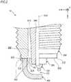
- Fig. 2 is an enlarged explanatory view illustrating the leading end side of the spark plug 10.
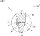
- Fig. 3 is a further enlarged explanatory view illustrating a cross section of a portion in which the ground electrode 400 is welded to the metal shell 300.
- a chamfered portion 312 is formed on an outer peripheral side of the end surface 310.
- the chamfered portion 312 is an angular surface.
- the chamfered portion 312 may be a round surface.
- the chamfered portion 312 may not be formed.
- a chamfered portion 319 is formed on an inner peripheral side of the end surface 310.
- the chamfered portion 319 is an angular surface.
- the chamfered portion 319 may be a round surface.
- the chamfered portion 319 may not be formed.
- a gap IG is formed between the inner peripheral surface 392 of the metal shell 300 and the first tubular portion 210 of the insulator 200.
- the gap IG prevents generation of the spark leak (lateral spark) causing generation of the spark discharge on the inner peripheral surface 392.
- Welding sag 700 which is formed when welding the ground electrode 400 to the end surface 310, exists on the periphery of the ground electrode 400 that is welded to the end surface 310 of the metal shell 300.
- the welding sag 700 formed when welding the ground electrode 400 at least a portion which is positioned on the inside of the metal shell 300 in a radial direction is removed.
- the welding sag 700 does not remain on the inner peripheral surface 392 of the metal shell 300.
- the welding sag 700 may not be completely removed from the inner peripheral surface 392 and may remain on the inner peripheral surface 392.
- the welding sag 700 does not remain on the inner peripheral surface 392 and the chamfered portion 319.
- the welding sag 700 may not be completely removed from the chamfered portion 319 and may remain on the chamfered portion 319.
- the welding sag 700 has a cross section 740 exposed to the inside of the metal shell 300 in the radial direction.
- the cross section 740 is formed when removing the welding sag 700 from the inner peripheral surface 392 after the ground electrode 400 is welded to the end surface 310.
- the cross section 740 is a surface along the Z axis.
- the cross section 740 is a cross section connected to the surface of the metal shell 300, and in the embodiment, is connected to the chamfered portion 319. In another embodiment, if the chamfered portion 319 is not formed, the cross section 740 may be a cross section connected to the inner peripheral surface 392.
- Fig. 4 is a process chart illustrating a manufacturing method of the spark plug 10.
- the manufacturer of the spark plug 10 manufactures a metal shell 300P which is to be manufactured into the metal shell 300 (process P132).
- the manufacturer manufactures the metal shell 300P by a pressing process and a cutting process.
- the metal shell 300P has a tubular shape to which at least the end surface 310 and the inner peripheral surface 392 are formed.
- the screw portion 320 is not formed to the metal shell 300P.
- the chamfered portion 312 and the chamfered portion 319 are formed to the metal shell 300P.
- the welding process is a process of welding a ground electrode 400P, which is to be manufactured into the ground electrode 400, to the end surface 310 of the metal shell 300P.
- the ground electrode 400P has a shape that is extended straight without being bent.
- Fig. 5 is an explanatory view illustrating a cross section of a portion of the metal shell 300P to which the ground electrode 400P is welded.
- the cross section of the portion of Fig. 5 illustrates a portion corresponding to the cross section of the portion of Fig. 3 .
- the manufacturer bonds the end surface 310 to the ground electrode 400P by resistance welding while pressing the ground electrode 400P against the end surface 310, in a state where the metal shell 300P is fixed such that the end surface 310 is directed upward in the vertical direction.
- the welding sag 700 is formed in the periphery of the ground electrode 400 on the end surface 310 by the welding process (process P134). In the welding process (process P134), the welding sag 700 is formed from the end surface 310 to the inner peripheral surface 392.
- the preliminary removing process is a process of removing the welding sag 700 from the inside of the metal shell 300P by a shearing process (punching process).
- the manufacturer removes the welding sag 700 from the inside of the metal shell 300P along a chain line CLA (see Fig. 5 ) positioned on the inside further than the inner peripheral surface 392.
- the manufacturer may remove the welding sag 700 from the inside of the metal shell 300P by a cutting process (for example, a milling process, a drilling process, and the like) in addition to the shearing process or instead of the shearing process.
- a cutting process for example, a milling process, a drilling process, and the like
- the removing process is a process of removing the welding sag 700 from the inside of the metal shell 300P by grinding.
- the manufacturer removes the welding sag 700 from the inside of the metal shell 300P along a chain line CLB (see Fig. 5 ) closer to the inner peripheral surface 392 than the chain line CLA.
- the chain line CLB has a shape along the chamfered portion 319 and the inner peripheral surface 392.
- a height Hm of Fig. 5 is a height of the welding sag 700 along a direction from the inner peripheral surface 392 of the metal shell 300P toward the inside of the metal shell 300P and perpendicular to the inner peripheral surface 392.
- the height Hm is a protrusion amount of the welding sag 700 protruding to the inside of the metal shell 300P.
- the manufacturer removes the welding sag 700 until the height Hm becomes 0.05 mm or less.
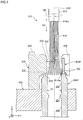
- Fig. 6 is an explanatory view illustrating a state of performing the removing process (process P136).
- the manufacturer removes the welding sag 700 from the inside of the metal shell 300P by using a tool 810 having a linear member 814.
- Fig. 7 is an explanatory view illustrating a configuration of the tool 810.
- the tool 810 includes a cylindrical portion 812 and the linear member 814.
- the cylindrical portion 812 of the tool 810 is a member having a cylindrical shape made of a metal and holds the linear member 814.
- the linear member 814 of the tool 810 is a member formed by linearly bonding ceramic fibers together.
- a material of the ceramic fiber of the linear member 814 contains alumina (Al 2 O 3 ) and silica (SiO 2 ) as main components.
- a bonding material (binder) for bonding ceramic fibers together may be an inorganic material or may be an organic material.
- the tool 810 may include one or more linear members 814, and in the embodiment, includes a plurality of linear members 814.
- a base end portion 814bs that is one end portion of the linear member 814 is a fixed end fixed to the cylindrical portion 812.
- a tip end portion 814tp that is the other end portion of the linear member 814 is a free end that is not fixed.
- the manufacturer reciprocates the tool 810 in an axial direction DA along an axial line CA2 while rotating the tool 810 in a rotation direction DR around the axial line CA2 of the metal shell 300P fixed to a jig 850.
- the tip end portion 814tp of the linear member 814 comes into contact with the welding sag 700 formed on the inside of the metal shell 300P while being bent to the outside by a centrifugal force due to the rotation.
- the welding sag 700 is grinded by the tip end portion 814tp of the linear member 814.
- the manufacturer provides a jig 830 having a through hole 832 at the end surface 310 side of the metal shell 300P when fixing the metal shell 300P to the jig 850.
- an axis of the through hole 832 in the jig 830 is positioned on the axial line CA2 of the metal shell 300P.
- the jig 830 comes into contact with the end surface 310 of the metal shell 300P.
- the jig 830 may be separated from the end surface 310 of the metal shell 300P.
- An inner diameter D1 of the inner peripheral surface 392 of the metal shell 300P is smaller than an inner diameter D2 of the through hole 832 of the jig 830.
- a relationship between the inner diameter D1 of the metal shell 300P and the inner diameter D2 of the jig 830 satisfies D1 ⁇ D2. It is preferable that the relationship between the inner diameter D1 and the inner diameter D2 satisfies D1 + 0.1 mm ⁇ D2 ⁇ D1 + 0.3 mm from the viewpoint of sufficient removal of the welding sag 700 and prevention of damage to the tool 810. An evaluation of the inner diameters D1 and D2 will be described later.
- Fig. 8 is an explanatory view illustrating a detailed configuration of the jig 830.
- the jig 830 has a chamfered portion 833 and a depression portion 834, a cutout portion 836, and a through hole 838 in addition to the through hole 832.
- the chamfered portion 833 of the jig 830 is an angular surface that is positioned opposite to the end surface 310 in a state where the jig 830 is provided to the metal shell 300P and is formed by chamfering one end portion of two end portions of the through hole 832.
- the depression portion 834 of the jig 830 is a portion that is formed by depressing a periphery of the other end portion positioned opposite to the chamfered portion 833 of the two end portions of the through hole 832 and forms a space into which the end surface 310 of the metal shell 300P enters.
- the cutout portion 836 of the jig 830 is a portion that is cut out along the through hole 832 and forms a space in which the ground electrode 400P and the welding sag 700 enter.
- a bolt 840 for fixing the jig 830 to the jig 850 enters the through hole 838 of the jig 830.
- the manufacturer forms the screw portion 320 to the metal shell 300P by performing a cutting process of the screw (process P138). Thereafter, the manufacturer performs surfacing process (plating process) on the metal shell 300P (process P139). Thereby, the metal shell 300 is completed.
- the manufacturer After the metal shell 300 is completed (process P139), the manufacturer combines other members (the center electrode 100, the insulator 200, and the like) to the metal shell 300 (process P180). Thereby, the spark plug 10 is completed.
- the manufacturer performs bending process to the ground electrode 400P when combining other members to the metal shell 300.
- Fig. 9 is a graph illustrating a result of a test in which the inner diameter D1 of the metal shell 300P and the inner diameter D2 of the jig 830 are evaluated.
- the evaluations of the inner diameters D1 and D2 are illustrated by taking the inner diameter D2 in a horizontal axis based on the inner diameter D1 and taking the height Hm of the welding sag 700 in a vertical axis.
- a tester prepared a plurality of jigs having inner diameters D2 different from the inner diameter D1 of the metal shell 300P and performed the removing process (process P136) using each jig. After performing the removing process (process P136), the tester measured the height Hm of the welding sag 700 on the metal shell 300P.
- the relationship between the inner diameter D1 and the inner diameter D2 satisfies D1 + 0.1 mm ⁇ D2 ⁇ D1 + 0.3 mm from the viewpoint of sufficient removal of the welding sag 700 and prevention of damage to the tool 810.
- the removing process since the welding sag 700 is grinded by the tip end portion 814tp of the linear member 814 bent to the outside by the centrifugal force due to the rotation, it is possible to effectively remove the welding sag 700 protruding to the inside of the metal shell 300P. Furthermore, since the welding sag 700 is grinded by the plurality of linear members 814, it is possible to more effectively remove the welding sag 700 protruding to the inside of the metal shell 300P.
- the tip end portion 814tp of the linear member 814 is caused to come into contact with the welding sag 700 by moving the tool 810 in the axial direction DA while rotating the tool 810 inside the through hole 832 of the jig 830.
- the relationship between the inner diameter D1 of the metal shell 300P in the inner peripheral surface 392 and the inner diameter D2 of the jig 830 in the through hole 832 satisfies D1 ⁇ D2.
- the relationship between the inner diameter D1 and the inner diameter D2 satisfies D1 + 0.1 mm ⁇ D2 ⁇ D1 + 0.3 mm.
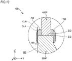
- Fig. 10 is an explanatory view illustrating a cross section of a portion of the metal shell 300P to which the ground electrode 400P is welded in a first modification example.
- the first modification example is similar to the embodiment described above other than that, in the removing process (process P136), the welding sag 700 is removed along a chain line CLB parallel to the inner peripheral surface 392. According to the first modification example, similar to the embodiment described above, it is possible to effectively remove the welding sag 700 protruding to the inside of the metal shell 300P.
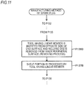
- Fig. 11 is a process chart illustrating a manufacturing method of a spark plug 10 in a second modification example.
- the second modification example is similar to the embodiment described above other than that a removing process (process P136B) is provided in which a using method of the tool 810 is different from that of the removing process (process P136) described above and a process (process P137B) for processing the shelf portion 394 of the metal shell 300P using the tool 810 is provided.
- the manufacturer inserts the linear member 814 of the tool 810 into the inner peripheral surface 392 from an opposite side of the end surface 310 of the metal shell 300P. Thereafter, the manufacturer causes the tip end portion 814tp of the linear member 814 to come into contact with the welding sag 700 while rotating the tool 810, in a state where the linear member 814 is inserted into the inner peripheral surface 392. As a result, the welding sag 700 is grinded by the tip end portion 814tp of the linear member 814.
- the manufacturer moves the tip end portion 814tp of the linear member 814 from the inner peripheral surface 392 to the opposite side of the end surface 310 while rotating the tool 810.
- the tip end portion 814tp of the linear member 814 comes into contact with the shelf portion 394.
- the shelf portion 394 is grinded by the tip end portion 814tp of the linear member 814.
- the manufacturer performs a process of forming the screw portion 320 (process P138) and thereafter.
- the second modification example described above similar to the embodiment described above, it is possible to effectively remove the welding sag 700 protruding to the inside of the metal shell 300P. Furthermore, it is possible to smoothly move the tool 810 in the axial direction DA without providing the jig 830 to the end surface 310 side of the metal shell 300P. Thus, it is possible to improve workability of the removing process (process P136B). Furthermore, after the welding sag 700 is removed (process P136B), it is possible to process the shelf portion 394 of the metal shell 300P together with the work for taking out the tool 810 from the metal shell 300P.
- the invention is not limited to the embodiment, the examples, and the modification examples described above, and can be realized by various configurations without departing from the scope of the invention.
- technical characteristics in the embodiment, the examples, and the modification examples corresponding to technical characteristics in each aspect described in the summary of the invention can be appropriately substituted or combined to solve a part or all of the problems described above or to obtain a part or all of the advantages described above.
- the technical characteristics can be appropriately removed if the technical characteristics are not described as essential technical characteristics in this specification.
- the inner peripheral surface 392 and the chamfered portion 319 of the metal shell may be a portion that is configured by the welding sag 700.
- the welding sag 700 may be removed from the inner peripheral surface 392 by performing the removing process (process P136) without performing the preliminary removing process (process P135).
Landscapes
- Engineering & Computer Science (AREA)
- Manufacturing & Machinery (AREA)
- Spark Plugs (AREA)
Claims (10)
- Herstellungsverfahren einer Zündkerze (10) zur Herstellung der Zündkerze (10) mit einer stabförmigen Mittelelektrode (100), die sich in axialer Richtung erstreckt, einem Isolator (200) mit einer rohrförmigen Form mit einer axialen Bohrung (290), der die Mittelelektrode (100) in der axialen Bohrung (290) hält, einer Metallhülle (300, 300P) mit einer rohrförmigen Form mit einer Endfläche (310) und einer inneren Umfangsfläche (392), wobei ein Spalt (IG) zwischen einer vorderen Endseite des Isolators und der inneren Umfangsfläche (392) gebildet ist, und einer mit der Endfläche (310) verschweißten Masseelektrode (400), wobei das Herstellungsverfahren umfasst:Schweißen der Masseelektrode (400) an die Endfläche (310); und das Verfahren ist gekennzeichnet durchEntfernen von Schweißdurchhang (700), der innerhalb der Metallhülle (300, 300P) durch das Schweißen gebildet ist, indem ein Spitzenendabschnitt (814tp) eines linearen Elements (814tp) mit dem Schweißdurchhang (700) in Kontakt kommt, während ein Werkzeug (810) gedreht wird, in dem ein Basisendabschnitt (814bs) des linearen Elements (814) befestigt ist.
- Herstellungsverfahren der Zündkerze (10) nach Anspruch 1,
wobei das lineare Element (814) durch lineares Verbinden von Keramikfasern miteinander gebildet ist,
wobei das Werkzeug (810) ein Werkzeug ist, in dem Basisendabschnitte (814s) einer Vielzahl der linearen Elemente (814) befestigt sind, und
wobei der Schweißdurchhang (700) entfernt wird, indem die Spitzenendabschnitte (814tp) der Vielzahl von linearen Elementen (814) veranlasst werden, mit dem Schweißdurchhang (700) in Kontakt zu kommen, während das Werkzeug (810) gedreht wird. - Herstellungsverfahren der Zündkerze (10) nach Anspruch 1 oder 2,
wobei das Entfernen Folgendes beinhaltetBereitstellen einer Vorrichtung (830) mit einem Durchgangsloch (832) an der Endflächenseite der Metallhülle (300, 300P), undVeranlassen, dass der Spitzenendabschnitt (814tp) des linearen Elements (814) mit dem Schweißdurchhang (700) in Kontakt kommt, indem das Werkzeug (810) in axialer Richtung (DA) bewegt wird, während das Werkzeug innerhalb der Durchgangsbohrung (838) gedreht wird. - Herstellungsverfahren der Zündkerze (10) nach Anspruch 3,
wobei eine Beziehung zwischen einem Innendurchmesser D1 der inneren Umfangsfläche (392) der Metallhülle (300, 300P) und einem Innendurchmesser D2 der Durchgangsbohrung (838) der Vorrichtung (830) D1 < D2 erfüllt. - Herstellungsverfahren der Zündkerze (10) nach Anspruch 4,
wobei die Beziehung zwischen dem Innendurchmesser D1 und dem Innendurchmesser D2 folgendes erfüllt: D1 + 0,1 mm ≤ D2 ≤ D1 + 0,3 mm. - Herstellungsverfahren der Zündkerze (10) nach Anspruch 1 oder 2,
wobei das Entfernen Folgendes beinhaltetEinsetzen des linearen Elements (814) in die innere Umfangsfläche (392) von einer gegenüberliegenden Seite der Endfläche der Metallhülle (300, 300P), undVeranlassen, dass der Spitzenendabschnitt (814tp) des linearen Elements (814) mit dem Schweißdurchhang (700) in Kontakt kommt, während das Werkzeug (810) gedreht wird, in einem Zustand, in dem das lineare Element (814) von der gegenüberliegenden Seite in die innere Umfangsfläche (392) eingeführt wird. - Herstellungsverfahren der Zündkerze (10) nach Anspruch 6,
wobei die Metallhülle (300, 300P) einen Ablageabschnitt (394) aufweist, der auf der gegenüberliegenden Seite weiter als die innere Umfangsfläche (392) positioniert ist,
wobei der Innendurchmesser des Ablageabschnitts (394) der Metallhülle kleiner ist als der Innendurchmesser der inneren Umfangsfläche (392) der Metallhülle (300, 300P), und
wobei das Entfernen ferner beinhaltet, dass der Spitzenendabschnitt (814tp) des linearen Elements (814) mit dem Ablageabschnitt (700) in Kontakt gebracht wird, indem der Spitzenendabschnitt von der inneren Umfangsfläche (392) zur gegenüberliegenden Seite bewegt wird, während das Werkzeug (810) gedreht wird, nachdem der Schweißdurchhang (700) entfernt wurde. - Herstellungsverfahren der Zündkerze (10) nach einem der Ansprüche 1 bis 7,
wobei der Schweißdurchhang (700) entfernt wird, bis eine Höhe des Schweißdurchhangs (700) 0,05 mm oder weniger entlang einer Richtung von der inneren Umfangsfläche (392) zur Innenseite der Metallhülle (300, 300P) und senkrecht zur inneren Umfangsfläche (392) wird. - Herstellungsverfahren der Zündkerze (10) nach einem der Ansprüche 1 bis 8, ferner umfassend:
Bilden einer männlichen Schraube (320) mit einem Nenndurchmesser von M10 oder weniger an einem Außenumfang der Metallhülle (300, 300P). - Herstellungsverfahren der Zündkerze (10) nach einem der Ansprüche 1 bis 9,
wobei der Spitzenendabschnitt (814tp) des linearen Elements ein freies Ende ist, das nicht fixiert ist.
Applications Claiming Priority (1)
| Application Number | Priority Date | Filing Date | Title |
|---|---|---|---|
| JP2014104897A JP5996578B2 (ja) | 2014-05-21 | 2014-05-21 | スパークプラグの製造方法 |
Publications (2)
| Publication Number | Publication Date |
|---|---|
| EP2947732A1 EP2947732A1 (de) | 2015-11-25 |
| EP2947732B1 true EP2947732B1 (de) | 2019-08-14 |
Family
ID=53188964
Family Applications (1)
| Application Number | Title | Priority Date | Filing Date |
|---|---|---|---|
| EP15168638.3A Active EP2947732B1 (de) | 2014-05-21 | 2015-05-21 | Herstellungsverfahren einer zündkerze |
Country Status (4)
| Country | Link |
|---|---|
| US (1) | US9190814B1 (de) |
| EP (1) | EP2947732B1 (de) |
| JP (1) | JP5996578B2 (de) |
| CN (1) | CN105098605A (de) |
Families Citing this family (1)
| Publication number | Priority date | Publication date | Assignee | Title |
|---|---|---|---|---|
| JP6273303B2 (ja) | 2016-01-25 | 2018-01-31 | 日本特殊陶業株式会社 | スパークプラグの製造方法 |
Family Cites Families (13)
| Publication number | Priority date | Publication date | Assignee | Title |
|---|---|---|---|---|
| JPS5134570A (ja) * | 1974-09-17 | 1976-03-24 | Toa Seiki Co Ltd | Kensakukogu |
| JPS51102363A (ja) * | 1975-03-06 | 1976-09-09 | Sugimoto Soki Kogyo Kk | Katsutaaburashopureeto |
| JPS6394665U (de) * | 1986-12-06 | 1988-06-18 | ||
| JPH07102504B2 (ja) * | 1989-03-01 | 1995-11-08 | 新日本製鐵株式会社 | 無機繊維強化樹脂よりなる回転工具 |
| TW222668B (de) * | 1992-03-19 | 1994-04-21 | Minnesota Mining & Mfg | |
| EP1106102B1 (de) * | 1995-04-28 | 2006-11-02 | Minnesota Mining And Manufacturing Company | Mit Schleifmittel versehene Bürste oder Bürstenborsten |
| JP4064114B2 (ja) * | 2002-01-31 | 2008-03-19 | 日本特殊陶業株式会社 | スパークプラグの製造方法 |
| WO2011033902A1 (ja) * | 2009-09-18 | 2011-03-24 | 日本特殊陶業株式会社 | スパークプラグ |
| CN102576982B (zh) * | 2009-10-23 | 2016-08-24 | 日本特殊陶业株式会社 | 火花塞及火花塞的制造方法 |
| JP5144818B2 (ja) * | 2010-05-13 | 2013-02-13 | 日本特殊陶業株式会社 | スパークプラグ |
| JP5303006B2 (ja) | 2011-06-14 | 2013-10-02 | 日本特殊陶業株式会社 | 内燃機関用スパークプラグの製造方法 |
| JP5331179B2 (ja) * | 2011-09-12 | 2013-10-30 | 日本特殊陶業株式会社 | スパークプラグの製造方法 |
| JP5878880B2 (ja) * | 2013-02-13 | 2016-03-08 | 日本特殊陶業株式会社 | スパークプラグおよびその製造方法 |
-
2014
- 2014-05-21 JP JP2014104897A patent/JP5996578B2/ja not_active Expired - Fee Related
-
2015
- 2015-05-21 CN CN201510264255.3A patent/CN105098605A/zh active Pending
- 2015-05-21 EP EP15168638.3A patent/EP2947732B1/de active Active
- 2015-05-21 US US14/718,424 patent/US9190814B1/en not_active Expired - Fee Related
Non-Patent Citations (1)
| Title |
|---|
| None * |
Also Published As
| Publication number | Publication date |
|---|---|
| CN105098605A (zh) | 2015-11-25 |
| JP5996578B2 (ja) | 2016-09-21 |
| US9190814B1 (en) | 2015-11-17 |
| US20150340847A1 (en) | 2015-11-26 |
| EP2947732A1 (de) | 2015-11-25 |
| JP2015220191A (ja) | 2015-12-07 |
Similar Documents
| Publication | Publication Date | Title |
|---|---|---|
| CN101689753B (zh) | 火花塞及其制造方法 | |
| KR20140022435A (ko) | 스파크 플러그 전극 구성 | |
| EP2259393A1 (de) | Zündkerze | |
| JP5878880B2 (ja) | スパークプラグおよびその製造方法 | |
| JP4975172B1 (ja) | スパークプラグの製造方法 | |
| JP6114780B2 (ja) | 点火プラグおよび点火装置 | |
| US9859688B1 (en) | Remanufactured sparkplug and sparkplug remanufacturing method | |
| US10256610B2 (en) | Spark plug | |
| EP2947732A1 (de) | Herstellungsverfahren einer zündkerze | |
| JP5449581B2 (ja) | スパークプラグ | |
| JP4520320B2 (ja) | スパークプラグおよびその絶縁碍子の製造方法 | |
| EP2706631A2 (de) | Zündkerze | |
| EP3565069B1 (de) | Zündkerze und verfahren zur herstellung einer zündkerze | |
| JP3534497B2 (ja) | スパークプラグの製造方法 | |
| CN105874664B (zh) | 火花塞 | |
| US9166376B2 (en) | Spark plug | |
| JP7070196B2 (ja) | 内燃機関用のスパークプラグ | |
| JP5451676B2 (ja) | スパークプラグの製造方法 | |
| JP6333135B2 (ja) | スパークプラグ | |
| JP5877874B2 (ja) | プラグ接続具、および、プラグ接続具の製造方法 | |
| JP2013098023A (ja) | スパークプラグの製造方法 |
Legal Events
| Date | Code | Title | Description |
|---|---|---|---|
| PUAI | Public reference made under article 153(3) epc to a published international application that has entered the european phase |
Free format text: ORIGINAL CODE: 0009012 |
|
| AK | Designated contracting states |
Kind code of ref document: A1 Designated state(s): AL AT BE BG CH CY CZ DE DK EE ES FI FR GB GR HR HU IE IS IT LI LT LU LV MC MK MT NL NO PL PT RO RS SE SI SK SM TR |
|
| AX | Request for extension of the european patent |
Extension state: BA ME |
|
| 17P | Request for examination filed |
Effective date: 20160310 |
|
| RBV | Designated contracting states (corrected) |
Designated state(s): AL AT BE BG CH CY CZ DE DK EE ES FI FR GB GR HR HU IE IS IT LI LT LU LV MC MK MT NL NO PL PT RO RS SE SI SK SM TR |
|
| GRAP | Despatch of communication of intention to grant a patent |
Free format text: ORIGINAL CODE: EPIDOSNIGR1 |
|
| STAA | Information on the status of an ep patent application or granted ep patent |
Free format text: STATUS: GRANT OF PATENT IS INTENDED |
|
| INTG | Intention to grant announced |
Effective date: 20190401 |
|
| GRAS | Grant fee paid |
Free format text: ORIGINAL CODE: EPIDOSNIGR3 |
|
| GRAA | (expected) grant |
Free format text: ORIGINAL CODE: 0009210 |
|
| STAA | Information on the status of an ep patent application or granted ep patent |
Free format text: STATUS: THE PATENT HAS BEEN GRANTED |
|
| AK | Designated contracting states |
Kind code of ref document: B1 Designated state(s): AL AT BE BG CH CY CZ DE DK EE ES FI FR GB GR HR HU IE IS IT LI LT LU LV MC MK MT NL NO PL PT RO RS SE SI SK SM TR |
|
| REG | Reference to a national code |
Ref country code: GB Ref legal event code: FG4D |
|
| REG | Reference to a national code |
Ref country code: CH Ref legal event code: EP Ref country code: AT Ref legal event code: REF Ref document number: 1168142 Country of ref document: AT Kind code of ref document: T Effective date: 20190815 |
|
| REG | Reference to a national code |
Ref country code: DE Ref legal event code: R096 Ref document number: 602015035685 Country of ref document: DE |
|
| REG | Reference to a national code |
Ref country code: IE Ref legal event code: FG4D |
|
| REG | Reference to a national code |
Ref country code: NL Ref legal event code: MP Effective date: 20190814 |
|
| REG | Reference to a national code |
Ref country code: LT Ref legal event code: MG4D |
|
| PG25 | Lapsed in a contracting state [announced via postgrant information from national office to epo] |
Ref country code: NL Free format text: LAPSE BECAUSE OF FAILURE TO SUBMIT A TRANSLATION OF THE DESCRIPTION OR TO PAY THE FEE WITHIN THE PRESCRIBED TIME-LIMIT Effective date: 20190814 Ref country code: BG Free format text: LAPSE BECAUSE OF FAILURE TO SUBMIT A TRANSLATION OF THE DESCRIPTION OR TO PAY THE FEE WITHIN THE PRESCRIBED TIME-LIMIT Effective date: 20191114 Ref country code: HR Free format text: LAPSE BECAUSE OF FAILURE TO SUBMIT A TRANSLATION OF THE DESCRIPTION OR TO PAY THE FEE WITHIN THE PRESCRIBED TIME-LIMIT Effective date: 20190814 Ref country code: SE Free format text: LAPSE BECAUSE OF FAILURE TO SUBMIT A TRANSLATION OF THE DESCRIPTION OR TO PAY THE FEE WITHIN THE PRESCRIBED TIME-LIMIT Effective date: 20190814 Ref country code: FI Free format text: LAPSE BECAUSE OF FAILURE TO SUBMIT A TRANSLATION OF THE DESCRIPTION OR TO PAY THE FEE WITHIN THE PRESCRIBED TIME-LIMIT Effective date: 20190814 Ref country code: NO Free format text: LAPSE BECAUSE OF FAILURE TO SUBMIT A TRANSLATION OF THE DESCRIPTION OR TO PAY THE FEE WITHIN THE PRESCRIBED TIME-LIMIT Effective date: 20191114 Ref country code: PT Free format text: LAPSE BECAUSE OF FAILURE TO SUBMIT A TRANSLATION OF THE DESCRIPTION OR TO PAY THE FEE WITHIN THE PRESCRIBED TIME-LIMIT Effective date: 20191216 Ref country code: LT Free format text: LAPSE BECAUSE OF FAILURE TO SUBMIT A TRANSLATION OF THE DESCRIPTION OR TO PAY THE FEE WITHIN THE PRESCRIBED TIME-LIMIT Effective date: 20190814 |
|
| REG | Reference to a national code |
Ref country code: AT Ref legal event code: MK05 Ref document number: 1168142 Country of ref document: AT Kind code of ref document: T Effective date: 20190814 |
|
| PG25 | Lapsed in a contracting state [announced via postgrant information from national office to epo] |
Ref country code: LV Free format text: LAPSE BECAUSE OF FAILURE TO SUBMIT A TRANSLATION OF THE DESCRIPTION OR TO PAY THE FEE WITHIN THE PRESCRIBED TIME-LIMIT Effective date: 20190814 Ref country code: GR Free format text: LAPSE BECAUSE OF FAILURE TO SUBMIT A TRANSLATION OF THE DESCRIPTION OR TO PAY THE FEE WITHIN THE PRESCRIBED TIME-LIMIT Effective date: 20191115 Ref country code: RS Free format text: LAPSE BECAUSE OF FAILURE TO SUBMIT A TRANSLATION OF THE DESCRIPTION OR TO PAY THE FEE WITHIN THE PRESCRIBED TIME-LIMIT Effective date: 20190814 Ref country code: IS Free format text: LAPSE BECAUSE OF FAILURE TO SUBMIT A TRANSLATION OF THE DESCRIPTION OR TO PAY THE FEE WITHIN THE PRESCRIBED TIME-LIMIT Effective date: 20191214 Ref country code: AL Free format text: LAPSE BECAUSE OF FAILURE TO SUBMIT A TRANSLATION OF THE DESCRIPTION OR TO PAY THE FEE WITHIN THE PRESCRIBED TIME-LIMIT Effective date: 20190814 Ref country code: ES Free format text: LAPSE BECAUSE OF FAILURE TO SUBMIT A TRANSLATION OF THE DESCRIPTION OR TO PAY THE FEE WITHIN THE PRESCRIBED TIME-LIMIT Effective date: 20190814 |
|
| PG25 | Lapsed in a contracting state [announced via postgrant information from national office to epo] |
Ref country code: TR Free format text: LAPSE BECAUSE OF FAILURE TO SUBMIT A TRANSLATION OF THE DESCRIPTION OR TO PAY THE FEE WITHIN THE PRESCRIBED TIME-LIMIT Effective date: 20190814 |
|
| PG25 | Lapsed in a contracting state [announced via postgrant information from national office to epo] |
Ref country code: DK Free format text: LAPSE BECAUSE OF FAILURE TO SUBMIT A TRANSLATION OF THE DESCRIPTION OR TO PAY THE FEE WITHIN THE PRESCRIBED TIME-LIMIT Effective date: 20190814 Ref country code: PL Free format text: LAPSE BECAUSE OF FAILURE TO SUBMIT A TRANSLATION OF THE DESCRIPTION OR TO PAY THE FEE WITHIN THE PRESCRIBED TIME-LIMIT Effective date: 20190814 Ref country code: RO Free format text: LAPSE BECAUSE OF FAILURE TO SUBMIT A TRANSLATION OF THE DESCRIPTION OR TO PAY THE FEE WITHIN THE PRESCRIBED TIME-LIMIT Effective date: 20190814 Ref country code: IT Free format text: LAPSE BECAUSE OF FAILURE TO SUBMIT A TRANSLATION OF THE DESCRIPTION OR TO PAY THE FEE WITHIN THE PRESCRIBED TIME-LIMIT Effective date: 20190814 Ref country code: EE Free format text: LAPSE BECAUSE OF FAILURE TO SUBMIT A TRANSLATION OF THE DESCRIPTION OR TO PAY THE FEE WITHIN THE PRESCRIBED TIME-LIMIT Effective date: 20190814 Ref country code: AT Free format text: LAPSE BECAUSE OF FAILURE TO SUBMIT A TRANSLATION OF THE DESCRIPTION OR TO PAY THE FEE WITHIN THE PRESCRIBED TIME-LIMIT Effective date: 20190814 |
|
| PG25 | Lapsed in a contracting state [announced via postgrant information from national office to epo] |
Ref country code: IS Free format text: LAPSE BECAUSE OF FAILURE TO SUBMIT A TRANSLATION OF THE DESCRIPTION OR TO PAY THE FEE WITHIN THE PRESCRIBED TIME-LIMIT Effective date: 20200224 Ref country code: SM Free format text: LAPSE BECAUSE OF FAILURE TO SUBMIT A TRANSLATION OF THE DESCRIPTION OR TO PAY THE FEE WITHIN THE PRESCRIBED TIME-LIMIT Effective date: 20190814 Ref country code: CZ Free format text: LAPSE BECAUSE OF FAILURE TO SUBMIT A TRANSLATION OF THE DESCRIPTION OR TO PAY THE FEE WITHIN THE PRESCRIBED TIME-LIMIT Effective date: 20190814 Ref country code: SK Free format text: LAPSE BECAUSE OF FAILURE TO SUBMIT A TRANSLATION OF THE DESCRIPTION OR TO PAY THE FEE WITHIN THE PRESCRIBED TIME-LIMIT Effective date: 20190814 |
|
| REG | Reference to a national code |
Ref country code: DE Ref legal event code: R097 Ref document number: 602015035685 Country of ref document: DE |
|
| PLBE | No opposition filed within time limit |
Free format text: ORIGINAL CODE: 0009261 |
|
| STAA | Information on the status of an ep patent application or granted ep patent |
Free format text: STATUS: NO OPPOSITION FILED WITHIN TIME LIMIT |
|
| PG2D | Information on lapse in contracting state deleted |
Ref country code: IS |
|
| 26N | No opposition filed |
Effective date: 20200603 |
|
| PG25 | Lapsed in a contracting state [announced via postgrant information from national office to epo] |
Ref country code: SI Free format text: LAPSE BECAUSE OF FAILURE TO SUBMIT A TRANSLATION OF THE DESCRIPTION OR TO PAY THE FEE WITHIN THE PRESCRIBED TIME-LIMIT Effective date: 20190814 |
|
| PG25 | Lapsed in a contracting state [announced via postgrant information from national office to epo] |
Ref country code: MC Free format text: LAPSE BECAUSE OF FAILURE TO SUBMIT A TRANSLATION OF THE DESCRIPTION OR TO PAY THE FEE WITHIN THE PRESCRIBED TIME-LIMIT Effective date: 20190814 Ref country code: LI Free format text: LAPSE BECAUSE OF NON-PAYMENT OF DUE FEES Effective date: 20200531 Ref country code: CH Free format text: LAPSE BECAUSE OF NON-PAYMENT OF DUE FEES Effective date: 20200531 |
|
| REG | Reference to a national code |
Ref country code: BE Ref legal event code: MM Effective date: 20200531 |
|
| GBPC | Gb: european patent ceased through non-payment of renewal fee |
Effective date: 20200521 |
|
| PG25 | Lapsed in a contracting state [announced via postgrant information from national office to epo] |
Ref country code: LU Free format text: LAPSE BECAUSE OF NON-PAYMENT OF DUE FEES Effective date: 20200521 |
|
| PG25 | Lapsed in a contracting state [announced via postgrant information from national office to epo] |
Ref country code: IE Free format text: LAPSE BECAUSE OF NON-PAYMENT OF DUE FEES Effective date: 20200521 Ref country code: GB Free format text: LAPSE BECAUSE OF NON-PAYMENT OF DUE FEES Effective date: 20200521 Ref country code: FR Free format text: LAPSE BECAUSE OF NON-PAYMENT OF DUE FEES Effective date: 20200531 |
|
| PG25 | Lapsed in a contracting state [announced via postgrant information from national office to epo] |
Ref country code: BE Free format text: LAPSE BECAUSE OF NON-PAYMENT OF DUE FEES Effective date: 20200531 |
|
| PGFP | Annual fee paid to national office [announced via postgrant information from national office to epo] |
Ref country code: DE Payment date: 20210427 Year of fee payment: 7 |
|
| PG25 | Lapsed in a contracting state [announced via postgrant information from national office to epo] |
Ref country code: MT Free format text: LAPSE BECAUSE OF FAILURE TO SUBMIT A TRANSLATION OF THE DESCRIPTION OR TO PAY THE FEE WITHIN THE PRESCRIBED TIME-LIMIT Effective date: 20190814 Ref country code: CY Free format text: LAPSE BECAUSE OF FAILURE TO SUBMIT A TRANSLATION OF THE DESCRIPTION OR TO PAY THE FEE WITHIN THE PRESCRIBED TIME-LIMIT Effective date: 20190814 |
|
| PG25 | Lapsed in a contracting state [announced via postgrant information from national office to epo] |
Ref country code: MK Free format text: LAPSE BECAUSE OF FAILURE TO SUBMIT A TRANSLATION OF THE DESCRIPTION OR TO PAY THE FEE WITHIN THE PRESCRIBED TIME-LIMIT Effective date: 20190814 |
|
| REG | Reference to a national code |
Ref country code: DE Ref legal event code: R119 Ref document number: 602015035685 Country of ref document: DE |
|
| PG25 | Lapsed in a contracting state [announced via postgrant information from national office to epo] |
Ref country code: DE Free format text: LAPSE BECAUSE OF NON-PAYMENT OF DUE FEES Effective date: 20221201 |