EP2941347B1 - Strengthened laminated glass structures - Google Patents
Strengthened laminated glass structures Download PDFInfo
- Publication number
- EP2941347B1 EP2941347B1 EP14701246.2A EP14701246A EP2941347B1 EP 2941347 B1 EP2941347 B1 EP 2941347B1 EP 14701246 A EP14701246 A EP 14701246A EP 2941347 B1 EP2941347 B1 EP 2941347B1
- Authority
- EP
- European Patent Office
- Prior art keywords
- glass
- laminated glass
- laminated
- sheet
- substrate
- Prior art date
- Legal status (The legal status is an assumption and is not a legal conclusion. Google has not performed a legal analysis and makes no representation as to the accuracy of the status listed.)
- Active
Links
Images


Classifications
-
- B—PERFORMING OPERATIONS; TRANSPORTING
- B32—LAYERED PRODUCTS
- B32B—LAYERED PRODUCTS, i.e. PRODUCTS BUILT-UP OF STRATA OF FLAT OR NON-FLAT, e.g. CELLULAR OR HONEYCOMB, FORM
- B32B17/00—Layered products essentially comprising sheet glass, or glass, slag, or like fibres
- B32B17/06—Layered products essentially comprising sheet glass, or glass, slag, or like fibres comprising glass as the main or only constituent of a layer, next to another layer of a specific material
- B32B17/061—Layered products essentially comprising sheet glass, or glass, slag, or like fibres comprising glass as the main or only constituent of a layer, next to another layer of a specific material of metal
-
- B—PERFORMING OPERATIONS; TRANSPORTING
- B32—LAYERED PRODUCTS
- B32B—LAYERED PRODUCTS, i.e. PRODUCTS BUILT-UP OF STRATA OF FLAT OR NON-FLAT, e.g. CELLULAR OR HONEYCOMB, FORM
- B32B15/00—Layered products comprising a layer of metal
- B32B15/18—Layered products comprising a layer of metal comprising iron or steel
-
- B—PERFORMING OPERATIONS; TRANSPORTING
- B32—LAYERED PRODUCTS
- B32B—LAYERED PRODUCTS, i.e. PRODUCTS BUILT-UP OF STRATA OF FLAT OR NON-FLAT, e.g. CELLULAR OR HONEYCOMB, FORM
- B32B15/00—Layered products comprising a layer of metal
- B32B15/20—Layered products comprising a layer of metal comprising aluminium or copper
-
- B—PERFORMING OPERATIONS; TRANSPORTING
- B32—LAYERED PRODUCTS
- B32B—LAYERED PRODUCTS, i.e. PRODUCTS BUILT-UP OF STRATA OF FLAT OR NON-FLAT, e.g. CELLULAR OR HONEYCOMB, FORM
- B32B7/00—Layered products characterised by the relation between layers; Layered products characterised by the relative orientation of features between layers, or by the relative values of a measurable parameter between layers, i.e. products comprising layers having different physical, chemical or physicochemical properties; Layered products characterised by the interconnection of layers
- B32B7/02—Physical, chemical or physicochemical properties
- B32B7/022—Mechanical properties
-
- B—PERFORMING OPERATIONS; TRANSPORTING
- B32—LAYERED PRODUCTS
- B32B—LAYERED PRODUCTS, i.e. PRODUCTS BUILT-UP OF STRATA OF FLAT OR NON-FLAT, e.g. CELLULAR OR HONEYCOMB, FORM
- B32B7/00—Layered products characterised by the relation between layers; Layered products characterised by the relative orientation of features between layers, or by the relative values of a measurable parameter between layers, i.e. products comprising layers having different physical, chemical or physicochemical properties; Layered products characterised by the interconnection of layers
- B32B7/02—Physical, chemical or physicochemical properties
- B32B7/027—Thermal properties
-
- B—PERFORMING OPERATIONS; TRANSPORTING
- B32—LAYERED PRODUCTS
- B32B—LAYERED PRODUCTS, i.e. PRODUCTS BUILT-UP OF STRATA OF FLAT OR NON-FLAT, e.g. CELLULAR OR HONEYCOMB, FORM
- B32B7/00—Layered products characterised by the relation between layers; Layered products characterised by the relative orientation of features between layers, or by the relative values of a measurable parameter between layers, i.e. products comprising layers having different physical, chemical or physicochemical properties; Layered products characterised by the interconnection of layers
- B32B7/04—Interconnection of layers
- B32B7/10—Interconnection of layers at least one layer having inter-reactive properties
-
- B—PERFORMING OPERATIONS; TRANSPORTING
- B32—LAYERED PRODUCTS
- B32B—LAYERED PRODUCTS, i.e. PRODUCTS BUILT-UP OF STRATA OF FLAT OR NON-FLAT, e.g. CELLULAR OR HONEYCOMB, FORM
- B32B7/00—Layered products characterised by the relation between layers; Layered products characterised by the relative orientation of features between layers, or by the relative values of a measurable parameter between layers, i.e. products comprising layers having different physical, chemical or physicochemical properties; Layered products characterised by the interconnection of layers
- B32B7/04—Interconnection of layers
- B32B7/12—Interconnection of layers using interposed adhesives or interposed materials with bonding properties
-
- B—PERFORMING OPERATIONS; TRANSPORTING
- B32—LAYERED PRODUCTS
- B32B—LAYERED PRODUCTS, i.e. PRODUCTS BUILT-UP OF STRATA OF FLAT OR NON-FLAT, e.g. CELLULAR OR HONEYCOMB, FORM
- B32B2307/00—Properties of the layers or laminate
- B32B2307/50—Properties of the layers or laminate having particular mechanical properties
- B32B2307/558—Impact strength, toughness
-
- Y—GENERAL TAGGING OF NEW TECHNOLOGICAL DEVELOPMENTS; GENERAL TAGGING OF CROSS-SECTIONAL TECHNOLOGIES SPANNING OVER SEVERAL SECTIONS OF THE IPC; TECHNICAL SUBJECTS COVERED BY FORMER USPC CROSS-REFERENCE ART COLLECTIONS [XRACs] AND DIGESTS
- Y10—TECHNICAL SUBJECTS COVERED BY FORMER USPC
- Y10T—TECHNICAL SUBJECTS COVERED BY FORMER US CLASSIFICATION
- Y10T428/00—Stock material or miscellaneous articles
- Y10T428/24—Structurally defined web or sheet [e.g., overall dimension, etc.]
- Y10T428/24942—Structurally defined web or sheet [e.g., overall dimension, etc.] including components having same physical characteristic in differing degree
- Y10T428/2495—Thickness [relative or absolute]
- Y10T428/24967—Absolute thicknesses specified
-
- Y—GENERAL TAGGING OF NEW TECHNOLOGICAL DEVELOPMENTS; GENERAL TAGGING OF CROSS-SECTIONAL TECHNOLOGIES SPANNING OVER SEVERAL SECTIONS OF THE IPC; TECHNICAL SUBJECTS COVERED BY FORMER USPC CROSS-REFERENCE ART COLLECTIONS [XRACs] AND DIGESTS
- Y10—TECHNICAL SUBJECTS COVERED BY FORMER USPC
- Y10T—TECHNICAL SUBJECTS COVERED BY FORMER US CLASSIFICATION
- Y10T428/00—Stock material or miscellaneous articles
- Y10T428/26—Web or sheet containing structurally defined element or component, the element or component having a specified physical dimension
- Y10T428/266—Web or sheet containing structurally defined element or component, the element or component having a specified physical dimension of base or substrate
Definitions
- the present disclosure relates to glass-laminate structures and, more particularly, to strengthened/damage and impact resistant laminated glass structures.
- Laminated glass structures may be used as components in the fabrication of various appliances, automobile components, architectural structures or electronic devices.
- laminated glass structures may be incorporated as cover glass for various end products such as refrigerators, decorative glazing, televisions, or as embedded touch laminates for smart interactive displays.
- applications that utilize laminated glass structures are subject to strength and impact limitations.
- some electronics require specially shaped laminated glass structures, such as laminated glass sheets with curved, shaped, beveled, bezeled, or otherwise contoured profiles. Accordingly, there is a need for apparatuses and methods for forming strengthened and/or impact resistant laminated glass structures.
- WO-A-2011147429 discloses a thin glass laminated with a metal whereby the glass is given compressive stress.
- US-A-2004052080 discloses a plasma display panel, and indicates that any glass type can be used, including soda lime, and the thickness is generally 0.5 to 5 mm. The glass is sandwiched between a metal back, and a breakage-prevention cover material made from polymers.
- US-A-4337997 discusses a reflector stack having a glass top layer, backed by a silver coating, a protective coating and a metal ply via bonding medium. When the reflector is curved so glass side is concave, the glass is in compression.
- GB-A-2074089 discusses glass bonded to metal via synthetic resin or polymer material.
- the glass may be chemically tempered.
- the glass thickness is between 0.6 and 1.0 mm.
- US-A-6287674 discloses a glass thickness is between 10 and 450 microns. This prior art shows shows that borosilicate glass has a higher strength than chemically strengthened glass, and chemical strengthening does not seem to decrease the probability of breakage.
- US-A-2011032205 discusses Schott Borofloat D263 and Corning 0211 as suitable glasses having a thickness of about 0.5 mm.
- the glass is brittle, therefore, laminate with a polymer.
- DE-U-9204379 discloses glass-wood laminates with high breaking resistance. Glass plates have a thickness of 3 mm or 4 mm or a thickness between 6 and 10 mm.
- US-A-2003077453 discloses a display device substrate to be used in production of panels for display devices, particularly liquid crystal display devices and organic EL devices.
- the display device substrate is composed of a pair of glass sheets facing each other and a layer of plastics material interposed between said paired glass sheets in such a way that said glass sheets have an internal compressive strain ascribed to the plastic sheet.
- One technique to improve the mechanical reliability of flexible glass is to laminate, or bond, the flexible glass to one or more laminate materials or substrates of unique structures.
- Flexible glass may be glass having a thickness of 300 microns or less, including but not limited to, 300, 275, 250, 225, 200, 190, 180, 170, 160, 150, 140, 130, 120, 110, 100, 90, 80, 70, 60, 50, 40, 30, 20, or 10 microns.
- a laminated glass structure can be designed to meet various mechanical requirements according to the concepts disclosed herein. When used properly, the laminated glass structures can offer improved mechanical reliability and impact resistance performance over an unlaminated flexible glass.
- impact resistance of a laminated glass structure may be defined by performance in a ball drop test using a ball drop testing apparatus.
- a stainless steel ball having a diameter of 51 mm and a weight of 535 g, is dropped from a state of rest and a fixed height onto a laminated glass structure supported by a foam block positioned on an aluminum table
- the laminated glass structure may deform such that a dimple is formed in the laminate material or substrate that the flexible glass is laminated or bonded to, while the flexible glass remains intact and adapts to the shape of the non-glass substrate.
- the laminated glass structure may be considered to have an impact resistance of the height the stainless steel ball was dropped from, in other words, the laminated glass structure may be said to have withstood such a ball drop test.
- the invention provides a laminated glass structure according to claim 1.
- the laminated glass structure comprising:
- the laminated glass structure wherein the laminated glass structure is supported by a sheet of 25.4 mm thick extruded polystyrene foam sheet that is positioned on top of an aluminum testing table such that the glass sheet is impacted by the ball and the non-glass substrate is facing the foam sheet.
- the laminated glass structure wherein the non-glass substrate comprises a metal or metal alloy.
- the laminated glass structure wherein the non-glass substrate comprises one or more of stainless steel, aluminum, nickel, brass, bronze, titanium, tungsten, copper, cast iron and noble metals.
- the laminated glass structure wherein the adhesive layer has a thickness of no more than about 1000 ⁇ m.
- the laminated glass structure wherein the adhesive layer is optically clear on cure.
- the laminated glass structure wherein no air bubbles within the adhesive layer have a diameter of greater than or equal to 100 microns.
- the laminated wherein the adhesive layer is opaque.
- the laminated glass wherein the adhesive layer is thermally cured.
- the laminated glass structure wherein the adhesive layer is cured by exposure to ultraviolet light.
- the laminated glass structure wherein the adhesive layer is a sheet or film of adhesive.
- the laminated glass structure of the aforementioned aspect wherein the sheet or film of adhesive has a decorative pattern visible through the glass sheet.
- the laminated glass structure wherein the non-glass substrate has a coefficient of thermal expansion (CTE) that is at least about 2 times a CTE of the glass sheet.
- CTE coefficient of thermal expansion
- the laminated glass structure wherein the compressive stress is at least about 80 MPa across its thickness.
- the laminated glass structure wherein the non-glass substrate has a CTE that is at least about 5 times a CTE of the glass sheet.
- the laminated glass structure wherein the glass sheet is a first glass sheet, the laminated structure comprising a second glass sheet, wherein the non-glass substrate is located between the first and second glass sheets.
- the laminated glass structure wherein the non-glass substrate has a Young's Modulus greater than or equal to about 30,000 MPa and less than or equal to about 500,000 MPa.
- the laminated glass structure wherein the glass sheet has a first CTE that is greater than or equal to about 2 ppm/C and less than or equal to about 5 ppm/C and the non-glass substrate has a second CTE greater than or equal to about 10 ppm/C.
- the laminated glass structure wherein the glass sheet has anti-microbial properties.
- Ranges can be expressed herein as from “about” one particular value, and/or to "about” another particular value. When such a range is expressed, another embodiment includes from the one particular value and/or to the other particular value. Similarly, when values arc expressed as approximations, by use of the antecedent "about,” it will be understood that the particular value forms another embodiment. It will be further understood that the endpoints of each of the ranges are significant both in relation to the other endpoint, and independently of the other endpoint.
- a laminated glass structure may be subjected to various kinds of static and dynamic mechanical stresses.
- Embodiments described herein generally relate to laminated glass structures where a flexible glass sheet is strengthened using a non-glass substrate.
- the non-glass substrate is a metal or metal alloy, such as stainless steel, aluminum, nickel, brass, bronze, titanium, tungsten, copper, cast iron or a noble metal.
- a relatively large coefficient of thermal expansion (CTE) mismatch between the non-glass substrate and the flexible glass sheet is utilized to improve the impact resistance by laminating the non-glass substrate to the flexible glass sheet at an elevated lamination temperature followed by a slow cooling.
- CTE coefficient of thermal expansion
- the laminated glass structure 200 is generally referred to as a symmetric laminated glass structure and includes a first outermost flexible glass layer 141 that is formed of a flexible glass sheet 140, a second outermost flexible glass layer 143 that is formed of another flexible glass sheet 140 and a non-glass substrate layer 133 that is sandwiched between and laminated to the first and second flexible glass layers 141 and 143.
- the non-glass substrate layer 133 is formed of a non-glass substrate 130, such as wood, metals, and/or metal alloys, for example stainless steel, copper, nickel, brass, bronze, titanium, tungsten, cast iron, aluminum, ceramic, composite, or another polymer or rigid material or combinations of these materials.
- the non-glass substrate 130 is formed of a metal or metal alloy.
- Adhesive layers 174, 175, may be formed of an adhesive material 170 that may be used to laminate the first and second flexible glass layers 141, 143 to the non-glass substrate layer 133 at the interfaces between their respective broad surfaces 134, 142 and 132, 148.
- the adhesive material 170 may be a non-adhesive interlayer, an adhesive, a sheet or film (which can be a dry film or a liquid film that is later cured) of adhesive, a liquid adhesive, a powder adhesive, a pressure sensitive adhesive, an ultraviolet light adhesive, a thermal adhesive, or other similar adhesive or combination thereof.
- the adhesive material 170 may assist in attaching the flexible glass 140 to the non-glass substrate 130 during lamination.
- adhesive material 170 are commercially available as Norland 68, 3M OCA 8211, 3M 8212, DuPont SentriGlas, DuPont PV 5411, silicones, acrylates, Japan World Corporation material FAS, encaptulant material, polyurethane, polyvinyl butyral resin, wood glue or like, or an optically clear adhesive.
- the adhesive layer 174 may be thin, having a thickness less than or equal to about 1000 ⁇ m, including less than or equal to about 900 ⁇ m, including less than or equal to about 800 ⁇ m, including less than or equal to about 700 ⁇ m, including less than or equal to about 600 ⁇ m, including less than or equal to about 500 ⁇ m, including less than or equal to about 400 ⁇ m, including less than or equal to about 300 ⁇ m, about 250 ⁇ m, including less than or equal to about 200 ⁇ m, including less than or equal to about 150 ⁇ m, including less than or equal to about 100 ⁇ m, less than or equal to about 50 ⁇ m, less than or equal to about 25 ⁇ m, and sub-micron thicknesses.
- the adhesives may also contain other functional components such as color, decoration, heat or UV resistance, anti-reflective (AR) filtration etc.
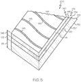
- the adhesive material 170 may be optically clear on cure, or may otherwise be opaque. In embodiments where the adhesive material 170 is a sheet or film of adhesive, the adhesive material 170 may have a decorative pattern or design visible through the thickness of the flexible glass, as shown in FIG. 5 .
- the laminated glass structure 200 includes an adhesive layer 174 formed of a sheet or film of adhesive material 170.
- the adhesive material 170 has a pattern of stripes 145 that are visible from the outer surface 144 of the flexible glass layer 141.
- Some air bubbles may become entrained in the laminated glass structure during or after lamination, but air bubbles having a diameter of equal to or less than 100 ⁇ m may not affect the impact resistance of the laminated glass structure. Formation of air bubbles may be reduced by use of a vacuum system or application of pressure to a surface of the structure.
- the flexible glass layer may be laminated without adhesive.
- the second flexible glass layer 143 may be formed of a flexible glass having a chemical composition different than the flexible glass sheet 140 of the first flexible glass layer 141. Manipulation of the bond strength between layers 141, 174, 133 of the laminated glass structure may also affect the impact resistance of the laminated glass structure.
- FIG. 1 illustrates outermost flexible glass layers 141, 143 in a symmetric laminated glass structure 200
- FIG. 3 illustrates an alternative laminated glass structure 202 with only a first outermost flexible glass layer 141 laminated to a non-glass substrate layer 133, generally referred to as an asymmetric laminated glass structure.
- an adhesive layer 174 may be used to laminate the first outermost flexible glass layer 141 to the non-glass substrate layer 133 at the interfaces between their respective broad surfaces 134, 142.
- FIG. 6 illustrates another laminated glass structure 204 including a first outermost flexible glass layer 141 laminated to a non-glass substrate layer 133 without the adhesive layer 174.
- FIGS. 1 , 3 , 5 and 6 illustrate exemplary laminated glass structures with a number of layers, however, other laminated glass structures having more or less layers may be utilized.
- the flexible glass sheet 140 may have a thickness 146 of about 0.3 mm or less including but not limited to thicknesses of, for example, about 0.01-0.05 mm, about 0.05-0.1 mm, about 0.1-0.15 mm, about 0.15-0.3 mm, 0.3, 0.275, 0.25, 0.225, 0.2, 0.19, 0.18, 0.17, 0.16, 0.15, 0.14, 0.13, 0.12, 0.11, 0.10, 0.09, 0.08 0.07, 0.06, 0.05, 0.04, 0.03, 0.02, or 0.01 mm.
- the flexible glass sheet 140 may be formed of glass, a glass ceramic, a ceramic material or composites thereof.
- a fusion process that forms high quality flexible glass sheets can be used in a variety of devices such as flat panel displays. Glass sheets produced in a fusion process have surfaces with superior flatness and smoothness when compared to glass sheets produced by other methods.
- the fusion process is described in U.S. Patent Serial Nos. 3, 338,696 and 3,682,609 .
- Other suitable glass sheet forming methods include a float process, updraw and slot draw methods.
- the flexible glass sheet 140 may also contain anti-microbial properties by using a chemical composition for the glass including an Ag ion concentration on the surface in the range greater than 0 to 0.047 ⁇ g/cm 2 , further described in U.S. Patent Application Publication No.
- the flexible glass 140 may also be coated with a glaze composed of silver, or otherwise doped with silver ions, to gain the desired anti-microbial properties, further described in U.S. Patent Application Publication No. 2011/0081542 A1 . Additionally, the flexible glass 140 may have a molar composition of 50% SiO 2 , 25% CaO, and 25% Na 2 O to achieve the desired anti-microbial effects.
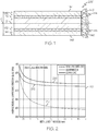
- exemplary stress diagrams 210 and 220 showing residual compressive stress in the flexible glass sheet 140 versus increasing non-glass substrate layer thickness are illustrated for the corresponding laminated glass structures 200 ( FIG. 1 ) and 202 ( FIG. 3 ).
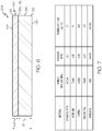
- the non-glass substrate layers 137 are formed of three different non-glass substrates 130: stainless steel, aluminum, and copper. The material properties of these non-glass substrates 130 are found in FIG. 7 .
- the residual compressive stresses in the flexible glass layers 141 and 143 (100 ⁇ m in thickness) of the laminated glass structure 200 are substantially uniform across the thicknesses of the flexible glass layers 141 and 143.
- the residual compressive stresses are generated by laminating the non-glass substrate 130 (of thicknesses ranging from about 0.1 mm to about 5 mm) to the flexible glass layers 141 and 143, as shown in FIG. 1 , at an elevated lamination temperature and then cooling to room temperature at a cooling rate depending on a thermal mass of the non-glass substrate 130, such as about 1.67 degrees Celsius per minute (3 degrees Fahrenheit per minute) or about 2.22 degrees Celsius per minute (4 degrees Fahrenheit per minute).
- the elevated lamination temperature is greater than room temperature and less than a deformation temperature specific to the non-glass substrate, including but not limited to about 165 degrees Celsius, about 140 degrees Celsius, or about 110 degrees Celsius.
- a deformation temperature specific to the non-glass substrate including but not limited to about 165 degrees Celsius, about 140 degrees Celsius, or about 110 degrees Celsius.
- the number of layers can be greater or less than three layers and selected depending on, for example, the end use and processing requirements.
- Various other layered laminate examples will be described herein.
- the residual compressive stresses in the flexible glass layer 141 (100 ⁇ m in thickness) of the laminated glass structure 202 may be substantially or almost uniform across the thickness of the flexible glass layer 141.
- the residual compressive stresses are generated by laminating the non-glass substrate 130 (of thicknesses ranging from about 0.1 mm to about 5 mm) to the flexible glass layer 141, as shown in FIG. 3 , at an elevated lamination temperature and then cooling to room temperature.
- the laminated glass structure of the present disclosure may have increased impact/damage resistance due to the presence of a compressive stress in the glass layer.
- the present disclosure provides apparatuses and methods for strengthening flexible glass sheets that utilizes a large CTE mismatch (e.g., about 2 times or more, such as about 5 times or more, such as about 10 times or more) between the non-glass substrate 130 and the flexible glass sheet 140 by laminating the non-glass substrate 130 and the flexible glass sheet 140 (e.g., as shown in FIG. 1 ) at an elevated lamination temperature and then slowly cooling to create a residual compressive stress across the thickness 146 of the flexible glass sheet 140.
- a large CTE mismatch e.g., about 2 times or more, such as about 5 times or more, such as about 10 times or more
- the non-glass substrate 130 should be allowed to thermally expand, at least to some degree, relative to the flexible glass sheet 140 due to the large CTE mismatch between the flexible glass sheet 140 and the non-glass substrate 130 before laminating the non-glass substrate 130 to the flexible glass sheet 140.
- the laminated glass structure 200 may be controllably cooled (e.g., preferably about 1-2 °C/min or less) back down to room temperature, fully curing the adhesive layers 174, 175, which introduces the compressive stress into the flexible glass 140.
- the CTE mismatch may be at least about 3 ppm/°C or more, such as about 6 ppm/°C or more, such as about 9 ppm/°C or more, such as about 12 ppm/°C or more, such as about 15 ppm/°C or more, such as about 20 ppm/°C or more, such as about 27 ppm/°C or more, such as about 50 ppm/°C or more.
- the laminated glass structures may be classified as symmetric (for example 200) and asymmetric (for example 202, 204). As explained above, the symmetric laminated glass structure 200 is constructed such that the layers below a central plane C (shown in FIG. 1 ) of the laminated glass structure 200 form a mirror image of the layers above the central plane C and asymmetric laminated glass structures 202, 204 do not have such a mirror image about their central planes.
- the compressive stress ⁇ g in the flexible glass can be increased by one or more of
- While larger compressive stresses (e.g., 30 MPa or more, such as 50 MPa or more, such as 60 MPA or more, such as about 70 MPa or more such as about 80 MPa or more, such as about 90 MPA or more, such as about 100 MPa or more, such as about 110 MPa or more) may be desired across the thickness 146 of the flexible glass sheet 140, there are limits on the amount of compressive stress that can be introduced.
- ⁇ g in the flexible glass sheet 140 one approach is to set the lamination temperature T lam as high as possible.
- the upper end of this lamination temperature T lam should not exceed limits set by specific properties of the laminated glass structure, such as the working temperature limit of any adhesive used.
- Any adhesive layer 174 will have minimal impact on the compressive stress ⁇ g , such as less than 10 MPa, across the thickness 146 of the flexible glass sheet 140 as the adhesive layer 174 is soft and may have a Young's modulus that is lower than both the Young's modulus of the flexible glass 140 and the non-glass substrate 130. Material and structural integrity should be considered in providing product reliability. Thus, various limits may affect the amount of compressive stress that can be introduced to the flexible glass sheet 140.
- ⁇ g_max ⁇ E g 1 ⁇ v g ⁇ m ⁇ ⁇ g T lam ⁇ T room .
- a maximum compressive stress ⁇ g_max may be generated in the flexible glass sheet 140 of 132 MPa for the symmetric laminated glass structure 200 where the metal substrate material is stainless steel, 190 MPa for a symmetric laminated glass structure 200 where the metal substrate material is aluminum, and 127 MPa for a symmetric laminated glass structure 200 where the metal substrate material is copper.
- Lamination processes may also be used to manipulate or affect stress profiles in asymmetric laminated glass structures, such as the laminated glass structures 202 and 204 ( FIGS. 3 and 5 ).
- the substrate material layer 133 may be allowed to thermally expand relative to the flexible glass 140 due to the large CTE mismatch between the flexible glass 140 and the non-glass substrate 130 before laminating the non-glass substrate 130 to the flexible glass 140.
- uniaxial or biaxial bending may be introduced in the flexible glass and the substrate material layer.
- the asymmetrical laminated glass structure 202, 204 may warp when cooled to room temperature.
- T lam refers to the curing temperature of the adhesive used in the lamination process
- T room refers to room temperature.
- E is replaced in the above equation by E 1 ⁇ v
- E is replaced in the above equation by E 1 ⁇ v 2 .
- bending characteristics of an asymmetric laminated glass structure can be determined where the material properties and lamination temperatures are known.
- the compressive stress ⁇ may not be uniform across the thickness 146 of the flexible glass sheet 140.
- the compressive stress ⁇ g_top across the thickness 146 of the flexible glass sheet 140 may be calculated using the following equation for a top surface 144, as positioned in FIGS.
- ⁇ g _ top ⁇ E g E m t m E m t m 3 + E g t g 2 2 t g + 3 t m E g 2 t g 4 + E m 2 t m 4 + 2 E g E m t g t m 2 t g 2 + 3 t g t m + 2 t m 2 ⁇ m ⁇ ⁇ g T lam ⁇ T room
- E Young's modulus
- ⁇ linear thermal expansion coefficient
- t total thicknesses of one type of material
- t total thicknesses of one type of material
- T lam refers to the curing temperature of the adhesive used in the lamination process
- T room refers to room temperature.
- the compressive stress ⁇ g_bot across the thickness 146 of the flexible glass sheet 140 may be calculated using the following equation for a bottom surface 148, as positioned in FIGS.
- ⁇ g _ bop ⁇ E g E m t m E m t m 3 + E g t g 2 4 t g + 3 t m E g 2 t g 4 + E m 2 t m 4 + 2 E g E m t g t m 2 t g 2 + 3 t g t m + 2 t m 2 ⁇ m ⁇ ⁇ g T lam ⁇ T room .
- E is replaced by E 1 ⁇ v .
- E uniaxial plane strain bending for any of the above referenced equations
- E is replaced by E 1 ⁇ v 2 .
- the compressive stress ⁇ in the flexible glass sheet 140 can be increased by one or more of the following:
- the adhesive layer 174 will typically have a minimal impact, such as less than 10 MPa, on the compressive stress ⁇ across the thickness 146 of the flexible glass sheet 140 as the adhesive layer 174 will typically be soft and have a Young's modulus that is lower than both the Young's modulus of the flexible glass 140 and the Young's modulus of the non-glass substrate 130. But it should be noted that the appropriate choice of the adhesive will enhance the impact resistance of the laminated structure through ionic or chemical bonding and/or mechanical structural interlock and shrinkage based compression. Finally, the maximum compressive stress ⁇ g max for asymmetric laminated glass structures is the same as for the symmetric laminated glass structures discussed above.
- Both symmetric and asymmetric laminated glass structure samples were formed according to the apparatuses and methods above.
- Each laminated glass structure sample had glass measuring 100 mm by 100 mm, a metal substrate measuring 101.6 mm by 101.6 mm, and an adhesive layer of DuPont PV having a thickness of 250 ⁇ m.
- a flexible glass sheet was laminated to three different substrate materials: stainless steel, aluminum, and copper, with material properties detailed in FIG. 7 .
- the sample laminated glass structures were found to have increased impact resistance capabilities and higher intrinsic strength when compared to other laminated glass structures with thicker glass and/or thicker metal substrates. Samples of laminated glass structures according to the present disclosure were tested in a ball drop test to determine impact resistance and found to have enhanced impact resistance and high intrinsic strength.
- the ball drop test apparatus 400 includes an aluminum testing table 410, a laminated glass structure sample 420, and a 535 gram weight stainless steel ball 430 having a diameter of 51 mm.
- a height adjustment mechanism 431 was used to adjust a ball drop height 432, starting from 15 cm and increasing in 5 cm increments until failure.
- a ball release mechanism 435 was positioned on an armature 433 that allowed for magnetic release of the stainless steel ball 430 from a state of rest. A vacuum and/or mechanical release may also be used.
- the ball 430 had a weight of 535 g and a diameter of 51 mm.
- a foam block 480 (e.g., Owens Corning Foamular 250 extruded polystyrene (XPS) foam) having a thickness of 25.4 mm was positioned underneath the laminated glass structure 420, supporting the entire area of the laminated glass structure 420.
- the foam block 480 may not be used and the laminated glass structure 420 can rest directly on the aluminum testing table 410.
- the aluminum testing table 410 was rigid and fully supported to ensure minimal energy absorption by the structure, and a height adjustment control device was employed to ensure ball drop height 432 accuracy.
- the procedure of the impact test performed in the instant application was as follows: the 535 g weight stainless steel ball 430 was dropped from a ball drop height 432 of 0.15 meters upon an upper surface 422 of the laminated glass structure sample 420 (with the glass facing up).
- the laminated glass structure sample 420 was positioned horizontally and was not constrained to the aluminum testing table 410.
- the stainless steel ball 430 was aimed and struck within a 5/8-inch diameter circle located at a geometric center of the laminated glass structure sample 420.
- the stainless steel ball 430 was not guided or otherwise restricted during freefall or prior to impact. Rather, the stainless steel ball 430 was dropped from a state of rest and from a fixed position at an initial velocity of 0 m/s. The stainless steel ball 430 was released and allowed to fall freely until impacting the glass sheet of the laminated glass structure sample 420.
- the upper surface 422 of the laminated glass structure sample 420 had to remain free from fracture.
- the laminated glass structure sample 420 was considered fractured if a crack propagated through the entire thickness of the glass in the laminated glass structure sample 420, or if any piece of the glass from the laminated glass structure sample 420 visible to the naked eye became detached from any surface of the laminated glass structure sample 420.
- the same laminated glass structure sample 420 passed the impact test corresponding to an impact resistance of height 432, the same laminated glass structure sample 420 was repositioned on the aluminum testing table 410, and the stainless steel ball 430 was again dropped, this time with the ball drop height 432 increased to 0.8 m. If the laminated glass structure sample 420 passed the impact test again, the ball drop height 432 was increased to 0.9 m, and increased by about 0.1 m for each subsequent impact test until failure was achieved or a ball drop height 432 of 1.45 m was reached corresponding to an impact resistance of 1.45 m. Ball drop heights 432 included 1 m, 1.295 m, and 1.45 m.
- a first set of laminated glass structure samples 440 had the following combination: flexible glass having a thickness of 100 ⁇ m, stainless steel substrate material having a thickness of 1.5875 mm, and 3M OCA8211 adhesive in between, having a thickness of 250 ⁇ m.
- a second set of laminated glass structure samples 450 had the following combination: flexible glass having a thickness of 100 ⁇ m, aluminum substrate material having a thickness of 0.8128 mm, and DuPont SentriGlas adhesive in between, having a thickness of 250 ⁇ m.
- a third set of laminated glass structure samples 460 had the following combination: flexible glass having a thickness of 100 ⁇ m, stainless steel substrate material having a thickness of 1.5875 mm, and DuPont SentriGlas adhesive in between, having a thickness of 250 ⁇ m.
- the ball drop test results of the three samples 440, 450, 460 arc provided in FIG. 10 .
- Each of the samples tested in all of the combinations survived impact from the ball drop test at a height of 0.8 m. Additionally, some samples exhibited an impact resistance of 1.45 m by surviving the ball dropped from a height of 1.45 m.
- the third combination appeared to have the highest consistent impact resistance measurements.
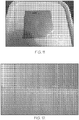
- one laminated glass sample 420 is shown that was subjected to the foam ball drop test described in FIG. 9 , with a starting ball drop height of 15 cm, increasing in 5 cm increments.
- the laminated glass sample 420 was tested until a ball drop height of 1.45 m was reached, and the laminated glass sample 420 successfully passed the ball drop test at a ball drop height of 1.45 m.
- the stainless steel ball 430 was dropped repeatedly onto the laminated glass structure sample 420 at increasing heights, the laminated glass structure deformed such that a dimple or depression was formed in the non-glass substrate 130 that the flexible glass sheet 140 was laminated to, while the flexible glass sheet 140 remained intact. As shown in FIG.
- the flexible glass sheet 140 adapted to the shape change, or dimple, of the non-glass substrate 130 without cracking.
- the particular laminated glass structure sample shown in FIG. 11 included flexible glass having a thickness of 100 ⁇ m, stainless steel substrate material having a 16 gauge, or 1.59 mm, thickness, and an adhesive layer of DuPont SentriGlas/PV5411 having a thickness of 250 ⁇ m. Because the flexible glass sheet 140 remained intact, as shown in FIG. 11 , the laminated glass sample 420 passed the ball drop test for the height 432.
- Various impact-related standards are described by IEC-60065 and UL-60950.
- Direct compressive stresses were measured in one laminated glass structure, where a Norland 68 UV adhesive having a sub-micron thickness was disposed between the glass and the non-glass substrate.
- the direct compressive stress measurement was made using a FSM-6000 prism-coupler instrument, and the results are shown in FIG. 12 . The results indicate birefringence in the laminated glass structure.
- a sample laminated glass structure as shown in FIG. 1 was formed using two flexible glass sheets, both 0.1 mm in thickness, and a layer formed of polymethyl methacrylate (PMMA), a transparent thermoplastic, having a thickness of 1.3 mm.
- PMMA polymethyl methacrylate
- a UV, or ultraviolet, sensitive adhesive (NOA 68 commercially available from Norland Products) was applied about 20 nm in thickness between the PMMA layer and the flexible glass layers.
- the laminated glass structure was placed on a thermoelectric hotplate and heated from one side maintained at 80 °C, which was below the UV sensitive adhesive's working limit of 90 °C.
- the UV sensitive adhesive was then cured using UV light applied to the UV sensitive adhesive from a side of the laminated glass structure opposite the thermoelectric hotplate to bond the metal layer at an elevated lamination temperature to the flexible glass layers and allowed to cool at a rate of 3 °C/min.
- About a 110 MPa compressive stress in the flexible glass was confirmed using birefringence measurements (FSM), shown in FIG. 12 .
- FSM birefringence measurements
- Table I Materials Material Young's modulus (GPa) Poisson's Ratio Coefficient of Thermal Expansion (10 -6 /°C) Thickness (mm) Lamination Temp/ Room Temp (°C) PMMA 2.5 0.37 90 1.3 80/20 Glass Substrate 73.6 0.23 3.17 0.1 (0.2 total) Table II: Stress Estimates Compressive Residual Stress in Glass Substrate (MPa) Tensile Residual Stress in PMMA (MPa) Estimate 105.8 16.3
- a metal layer may be heated to a temperature above the plastic softening temperature (glass transition temperature), but below the melting temperature for the metal.
- the softening temperature is 91 °C to 115 °C and the melting temperature is 160 °C.
- a combination of heat and pressure may be utilized (e.g., using an autoclave) to heat the metal layer to a temperature between the softening temperature and the melting temperature.
- the heated temperature may be held for a preselected period of time and then the laminated glass structure may be cooled at a predetermined rate (e.g., less than about 3 °F/min).
- adhesive materials 170 for laminating the non-glass substrates 130 to the flexible glass sheets 140 at elevated lamination temperatures include UV curable optical adhesives or optical cements such as those manufactured by NorlandTM Optical Adhesives (NOA60, NOA61, NOA63, NOA65, NOA68, NOA68T, NOA71, NOA72, NOA73, NOA74, NOA75, NOA76, NOA78, NOA81, NOA84, NOA88, NOA89), Dow CorningTM (Sylgard 184 and other thermally curing silicones), DymaxTM, and others.
- NorlandTM Optical Adhesives NOA60, NOA61, NOA63, NOA65, NOA68, NOA68T, NOA71, NOA72, NOA73, NOA74, NOA75, NOA76, NOA78, NOA81, NOA84, NOA88, NOA89
- Dow CorningTM Sylgard 184 and other thermally curing silicones
- DymaxTM and
- adhesive materials with activation temperatures of greater than a preselected temperature e.g., about 50 °C or more, such as about 70 °C or more, such as 80 °C or more, such as 100 °C or more
- a preselected temperature e.g., about 50 °C or more, such as about 70 °C or more, such as 80 °C or more, such as 100 °C or more
- each non-glass substrates may itself be a laminated or composite structure made of different types of metal having different Young's moduli, different Poisson's Ratios, and/or layer thicknesses.
- the compound layer may be homogenized to find effective values for the overall layer, including an effective thickness, an effective Young's modulus, and an effective Poisson's Ratio that may be used as described herein to beneficially configure a glass-metal laminate.
- the composites for example, may be formed of any combinations of the above materials and/or metals, such as stainless steel, nickel, copper, noble metals, metal oxides, etc.
- the laminated glass structures described herein may be a optically clear formable and/or flexible structure for use as a protective element in an electronic device, wherein the laminated glass structure is a composite structure comprising a layer of flexible glass sheet 140 of a thickness from 5 to 300 microns, and a layer of non-glass substrate 130, such as metal, ranging in thickness from 0.1 mm to 5 mm.
- the formability of the laminated glass structure allows it to deviate from full planarity by bending and/or twisting so it can adapt to the shape or form of some other object.
- the flexible glass sheet 140 and non-glass substrates 130 can be provided in sheet form according to a batch process.
- the flexible glass sheet 140 can be provided in sheet form and the non-glass substrate 130 from a continuous roll.
- both flexible glass sheet 140 and non-glass substrate 130 are from continuous rolls.
- non-glass substrate 130 it is possible to use polymers which can be deposited/coated as pre-polymers or pre-compounds and then converted, such as epoxy-resins, polyurethanes, phenol-formaldehyde resins, and melamine-formaldehyde resins.
- the lamination of the flexible glass 140 and non-glass substrates 130 can be with adhesive material 170 in between the layers.
- adhesive material 170 can be pre-coated onto one of the two or on both of the flexible glass sheet 140 and non-glass substrate 130 or otherwise supplied during the lamination process, at room or elevated lamination temperature and with or without pressure. UV-cured adhesives are also suitable.
- the non-glass substrate 130 can be in the form of metal sheets which are pre-coated with a heat-seal glue. Lamination and/or deposition of the non-glass substrate 130 onto the flexible glass sheet 140 can be integrated in the fabrication process of the glass, i.e. flexible glass comes off the fabrication line and is then (still hot or warm or cold) coated with the metal substrate.
- the above-described laminated glass structures provide increased strength to flexible glass. Nearly constant uniform compressive stress can be provided through the glass thickness for symmetric laminate glass structures.
- the substrate materials can provide breakage protection and hold the flexible glass together in the event of any breakage.
- the laminated glass structures can provide touch and cover glass, which could be used to replace chemically strengthened glass. Curved display glass, such as that discussed above in connection with asymmetric laminated glass structure can be provided.
- the flexible glass can also act as a hermetic moisture barrier, block undesired UV light, or inhibit corrosion of the underlying substrate.
- Laminated glass structures may also improve optical quality of the substrate material through the flexible glass, performance, strength, impact resistance, scratch resistance to the underlying substrate, and mechanical durability.
- the substrate material may be protected from scratches, fractures, or other damage by the layer of flexible glass in the laminated glass structure.
- the flexible glass on an outer surface of the laminated glass structure may be easier to clean than the surface of the substrate material.
- a refrigerator door made of a laminated glass structure with stainless steel laminated to flexible glass may be fingerprint-resistant
- a mobile electronic device battery cover made of a laminated glass structure with aluminum laminated to flexible glass may be scratch-resistant and easy to clean.
- Another possible use may be in inhibiting the patina effect in copper materials, for example, roofing or gutter materials, or planter boxes (wherein additionally, the glass surface facing the planting medium would inhibit the undesirable migration of copper into the plants) that are used in an environment containing moisture.
- non-glass substrates 130 can comprise a metal polarizer sheet, a contrast-enhancing filter-laminate, have anti-reflective properties, color filter properties or color conversion properties.
- the non-glass substrate 130 can be designed to block undesired ambient light and/or have scattering particles so that wave guiding is reduced and the brightness of the device is increased.
- the glass can have anti-microbial functionality. Such additional functionalities could be incorporated in the flexible glass 140.
- Polymer materials are easily scratched, degrade from environmental elements including sunlight exposure and provide poor moisture/oxygen barrier properties.
- Glass on the other hand, is scratch resistant, durable and is known for excellent moisture/oxygen barrier properties.
- glass has higher density compared to, for instance, metal, and is a brittle material where strength of glass is dictated by defects and flaws.
- the above described laminated glass structures and methods of making them take advantage of these two classes of materials and combining into one laminated structure having improved barrier properties, lightweight and higher mechanical reliability compared to a bare flexible glass stack.
Landscapes
- Physics & Mathematics (AREA)
- Thermal Sciences (AREA)
- Engineering & Computer Science (AREA)
- Mechanical Engineering (AREA)
- Laminated Bodies (AREA)
- Joining Of Glass To Other Materials (AREA)
Priority Applications (2)
| Application Number | Priority Date | Filing Date | Title |
|---|---|---|---|
| EP19163156.3A EP3533604A1 (en) | 2013-01-07 | 2014-01-06 | Strengthened laminated glass structures |
| EP19163146.4A EP3527363A1 (en) | 2013-01-07 | 2014-01-06 | Strengthened laminated glass structures |
Applications Claiming Priority (2)
| Application Number | Priority Date | Filing Date | Title |
|---|---|---|---|
| US201361749671P | 2013-01-07 | 2013-01-07 | |
| PCT/US2014/010287 WO2014107640A1 (en) | 2013-01-07 | 2014-01-06 | Strengthened laminated glass structures |
Related Child Applications (4)
| Application Number | Title | Priority Date | Filing Date |
|---|---|---|---|
| EP19163146.4A Division EP3527363A1 (en) | 2013-01-07 | 2014-01-06 | Strengthened laminated glass structures |
| EP19163146.4A Division-Into EP3527363A1 (en) | 2013-01-07 | 2014-01-06 | Strengthened laminated glass structures |
| EP19163156.3A Division EP3533604A1 (en) | 2013-01-07 | 2014-01-06 | Strengthened laminated glass structures |
| EP19163156.3A Division-Into EP3533604A1 (en) | 2013-01-07 | 2014-01-06 | Strengthened laminated glass structures |
Publications (2)
| Publication Number | Publication Date |
|---|---|
| EP2941347A1 EP2941347A1 (en) | 2015-11-11 |
| EP2941347B1 true EP2941347B1 (en) | 2021-06-02 |
Family
ID=50001308
Family Applications (3)
| Application Number | Title | Priority Date | Filing Date |
|---|---|---|---|
| EP14701246.2A Active EP2941347B1 (en) | 2013-01-07 | 2014-01-06 | Strengthened laminated glass structures |
| EP19163146.4A Withdrawn EP3527363A1 (en) | 2013-01-07 | 2014-01-06 | Strengthened laminated glass structures |
| EP19163156.3A Withdrawn EP3533604A1 (en) | 2013-01-07 | 2014-01-06 | Strengthened laminated glass structures |
Family Applications After (2)
| Application Number | Title | Priority Date | Filing Date |
|---|---|---|---|
| EP19163146.4A Withdrawn EP3527363A1 (en) | 2013-01-07 | 2014-01-06 | Strengthened laminated glass structures |
| EP19163156.3A Withdrawn EP3533604A1 (en) | 2013-01-07 | 2014-01-06 | Strengthened laminated glass structures |
Country Status (7)
| Country | Link |
|---|---|
| US (1) | US10131118B2 (enExample) |
| EP (3) | EP2941347B1 (enExample) |
| JP (1) | JP6278480B2 (enExample) |
| KR (1) | KR102136376B1 (enExample) |
| CN (1) | CN105517796B (enExample) |
| TW (1) | TWI637930B (enExample) |
| WO (1) | WO2014107640A1 (enExample) |
Families Citing this family (63)
| Publication number | Priority date | Publication date | Assignee | Title |
|---|---|---|---|---|
| CN105593014A (zh) | 2013-03-14 | 2016-05-18 | 康宁股份有限公司 | 用于制造和切割挠性玻璃和聚合物复合结构的方法和设备 |
| WO2014166082A1 (en) * | 2013-04-10 | 2014-10-16 | Schott Glass Technologies (Suzhou) Co. Ltd. | Flexible glass/metal foil composite articles and production process thereof |
| TWI631019B (zh) | 2013-04-19 | 2018-08-01 | 美商康寧公司 | 形成積層玻璃結構之方法 |
| DE102013011690B4 (de) * | 2013-07-12 | 2022-04-21 | e.solutions GmbH | Glasoberflächenverbund zur Anordnung vor einer optischen Anzeige, einem Bedienfeld und/ oder zur Verwendung als dekoratives Element, insbesondere in einem Kraftfahrzeug |
| US9321677B2 (en) | 2014-01-29 | 2016-04-26 | Corning Incorporated | Bendable glass stack assemblies, articles and methods of making the same |
| US20150276205A1 (en) * | 2014-03-27 | 2015-10-01 | Ge Lighting Solutions Llc | Lighting fixture with antimicrobial/antifungal sheet and clean room capability |
| CA2968232A1 (en) * | 2014-11-17 | 2016-05-26 | Corning Incorporated | Glass-polymer laminates and processes for forming the same |
| WO2016094282A1 (en) * | 2014-12-08 | 2016-06-16 | Corning Incorporated | Laminated glass article with low compaction and method for forming the same |
| US9990064B2 (en) * | 2015-03-24 | 2018-06-05 | Amazon Technologies, Inc. | Electronic device stack assembly |
| US20180154493A1 (en) * | 2015-04-22 | 2018-06-07 | Corning Incorporated | Methods of edge finishing laminated glass structures |
| EP3368310A1 (en) * | 2015-10-27 | 2018-09-05 | Corning Incorporated | Method of laminating ultra-thin glass to non-glass substrates |
| US10955311B2 (en) | 2015-11-18 | 2021-03-23 | Corning Incorporated | Apparatus and methods to determine stresses in cover glass of handheld devices |
| EP3397485B1 (en) * | 2015-12-29 | 2020-05-13 | Corning Incorporated | Asymmetric processing method for reducing bow in laminate structure and laminate structure |
| CN109071302B (zh) | 2016-03-09 | 2022-04-26 | 康宁股份有限公司 | 复杂弯曲玻璃制品的冷成形 |
| US10418585B2 (en) * | 2016-05-12 | 2019-09-17 | Samsung Display Co., Ltd. | Cover unit and display device having the same |
| TWI800484B (zh) | 2016-06-28 | 2023-05-01 | 美商康寧公司 | 層壓薄強化玻璃至用於裝飾及顯示器蓋應用的曲面模製塑膠表面 |
| WO2018009504A1 (en) | 2016-07-05 | 2018-01-11 | Corning Incorporated | Cold-formed glass article and assembly process thereof |
| KR102095935B1 (ko) | 2016-08-31 | 2020-04-01 | 코닝 인코포레이티드 | 향상된 평면도를 갖는 글라스 라미네이트 및 그 형성방법 |
| KR102245175B1 (ko) | 2016-10-12 | 2021-04-28 | 코닝 인코포레이티드 | 글라스 라미네이트 에지 다듬질을 위한 방법 및 장치 및 이에 의하여 형성되는 글라스 라미네이트 |
| US10953644B2 (en) | 2016-10-20 | 2021-03-23 | Corning Incorporated | Cold formed 3D cover glass articles and forming process to make the same |
| CN115403280B (zh) | 2016-10-25 | 2024-03-19 | 康宁公司 | 用于显示器的冷成形玻璃积层 |
| TWI767948B (zh) | 2016-10-31 | 2022-06-21 | 美商康寧公司 | 層狀可彎曲耐刺穿玻璃物件及製造方法 |
| US10452888B2 (en) * | 2016-11-24 | 2019-10-22 | Boe Technology Group Co., Ltd. | Flexible touch panel, flexible display panel and flexible display apparatus, and fabricating method thereof |
| EP3562712A1 (en) | 2016-12-30 | 2019-11-06 | Corning Incorporated | Glass-covered vehicle interior system and method for forming the same |
| US11016590B2 (en) | 2017-01-03 | 2021-05-25 | Corning Incorporated | Vehicle interior systems having a curved cover glass and display or touch panel and methods for forming the same |
| KR102445875B1 (ko) | 2017-01-03 | 2022-09-21 | 코닝 인코포레이티드 | 만곡된 커버 유리 및 디스플레이 또는 터치 패널을 갖는 차량 인테리어 시스템 및 이를 형성시키는 방법 |
| US10712850B2 (en) | 2017-01-03 | 2020-07-14 | Corning Incorporated | Vehicle interior systems having a curved cover glass and a display or touch panel and methods for forming the same |
| US11685684B2 (en) | 2017-05-15 | 2023-06-27 | Corning Incorporated | Contoured glass articles and methods of making the same |
| CN117962601A (zh) | 2017-07-18 | 2024-05-03 | 康宁公司 | 复杂弯曲玻璃制品的冷成型 |
| EP3681847B1 (en) | 2017-09-12 | 2025-01-29 | Corning Incorporated | Tactile elements for deadfronted glass and methods of making the same |
| US11065960B2 (en) | 2017-09-13 | 2021-07-20 | Corning Incorporated | Curved vehicle displays |
| TWI873668B (zh) | 2017-09-13 | 2025-02-21 | 美商康寧公司 | 用於顯示器的基於光導器的無電面板、相關的方法及載具內部系統 |
| TWI844520B (zh) | 2017-10-10 | 2024-06-11 | 美商康寧公司 | 具有改善可靠性的彎曲的覆蓋玻璃的車輛內部系統及其形成方法 |
| KR102515679B1 (ko) * | 2017-10-20 | 2023-03-29 | 코닝 인코포레이티드 | 향상된 표면파형을 갖는 라미네이티드 글라스 구조물 |
| WO2019103469A1 (en) | 2017-11-21 | 2019-05-31 | Corning Precision Materials Co., Ltd. | Aspheric mirror for head-up display system and methods for forming the same |
| CN111656254B (zh) | 2017-11-30 | 2023-06-02 | 康宁公司 | 用于真空成形非球面镜的系统与方法 |
| KR102605341B1 (ko) | 2017-11-30 | 2023-11-24 | 코닝 인코포레이티드 | 곡선형 미러를 성형하기 위한 진공 몰드 장치, 시스템, 및 방법 |
| KR102441930B1 (ko) | 2017-12-04 | 2022-09-14 | 삼성디스플레이 주식회사 | 플렉서블 표시 장치 및 플렉서블 표시 장치의 제조 방법 |
| WO2019169293A1 (en) | 2018-03-02 | 2019-09-06 | Corning Incorporated | Anti-reflective coatings and articles and methods of forming the same |
| US11718071B2 (en) | 2018-03-13 | 2023-08-08 | Corning Incorporated | Vehicle interior systems having a crack resistant curved cover glass and methods for forming the same |
| CN110377174A (zh) * | 2018-04-13 | 2019-10-25 | 佳冠电子股份有限公司 | 具高强度的粘合式玻璃 |
| CN112672984B (zh) | 2018-07-12 | 2023-03-10 | 康宁公司 | 配置用于色彩比对的无电板 |
| KR20210032976A (ko) | 2018-07-16 | 2021-03-25 | 코닝 인코포레이티드 | 냉간-벤딩 유리 기판을 갖는 차량 내부 시스템 및 이를 형성하기 위한 방법 |
| CN115611528B (zh) | 2018-07-23 | 2024-02-20 | 康宁公司 | 具有改善的头部冲击性能及破裂后能见度的汽车内部及覆盖玻璃制品 |
| KR102817845B1 (ko) | 2018-07-26 | 2025-06-09 | 코닝 인코포레이티드 | 냉간-성형된 만곡된 유리 물품 및 이를 제조하는 방법 |
| CN112867625B (zh) | 2018-08-20 | 2025-03-28 | 康宁公司 | 用于显示器或触控面板的具有强化的盖玻璃 |
| JP7410140B2 (ja) | 2018-10-18 | 2024-01-09 | コーニング インコーポレイテッド | 向上させられたヘッドフォーム衝撃性能を示す強化ガラス物品および同強化ガラス物品を組み込んだ自動車内装システム |
| EP3867091B1 (en) | 2018-10-18 | 2025-09-24 | Corning Incorporated | Frame for auto interior display panel |
| EP4465126B1 (en) | 2018-11-01 | 2025-12-17 | Corning Incorporated | Methods for uniform adhesive bondline control for 3d coldformed curved laminate |
| US12338169B2 (en) | 2018-11-16 | 2025-06-24 | Corning Incorporated | Glass ceramic devices and methods with tunable infrared transmittance |
| CN113195421B (zh) | 2018-11-21 | 2023-04-07 | 康宁公司 | 低存储拉伸能切割玻璃和优先裂纹碎裂 |
| US12291480B2 (en) | 2018-11-29 | 2025-05-06 | Corning Incorporated | Adhering glass cover sheet to a frame |
| CN113196373B (zh) | 2018-11-29 | 2024-07-23 | 康宁公司 | 动态可调的显示系统和动态调整显示器的方法 |
| KR20210097747A (ko) | 2018-11-30 | 2021-08-09 | 코닝 인코포레이티드 | 열적으로 매칭된 시스템을 갖는 냉간-성형 유리 물품 및 이를 형성하기 위한 공정 |
| EP3771695A1 (en) | 2019-07-31 | 2021-02-03 | Corning Incorporated | Method and system for cold-forming glass |
| US12466756B2 (en) | 2019-10-08 | 2025-11-11 | Corning Incorporated | Curved glass articles including a bumper piece configured to relocate bending moment from display region and method of manufacturing same |
| KR20210051027A (ko) * | 2019-10-29 | 2021-05-10 | 코닝 인코포레이티드 | 유리 라미네이트 물품 |
| CN113270025A (zh) * | 2020-02-14 | 2021-08-17 | 华为技术有限公司 | 柔性屏幕盖板、柔性显示面板、柔性屏和可折叠电子设备 |
| US11772361B2 (en) | 2020-04-02 | 2023-10-03 | Corning Incorporated | Curved glass constructions and methods for forming same |
| KR102824146B1 (ko) * | 2020-07-17 | 2025-06-23 | 코닝 인코포레이티드 | 유리 롤 |
| KR102902139B1 (ko) * | 2020-07-29 | 2025-12-18 | 엘지디스플레이 주식회사 | 플렉서블 표시 장치 |
| JP7621774B2 (ja) * | 2020-11-19 | 2025-01-27 | 株式会社 オプトクエスト | 光デバイス製造方法及び光デバイス |
| CN112582500A (zh) * | 2020-12-08 | 2021-03-30 | 陕西拓日新能源科技有限公司 | 一种双玻璃光伏组件生产工艺 |
Citations (1)
| Publication number | Priority date | Publication date | Assignee | Title |
|---|---|---|---|---|
| US20030077453A1 (en) * | 2001-10-18 | 2003-04-24 | Hitoshi Oaku | Display device substrate and display device formed therewith |
Family Cites Families (59)
| Publication number | Priority date | Publication date | Assignee | Title |
|---|---|---|---|---|
| US2392314A (en) * | 1943-03-02 | 1946-01-08 | Corning Glass Company | Glass-to-metal seal |
| US3338696A (en) | 1964-05-06 | 1967-08-29 | Corning Glass Works | Sheet forming apparatus |
| BE757057A (fr) | 1969-10-06 | 1971-04-05 | Corning Glass Works | Procede et appareil de controle d'epaisseur d'une feuille de verre nouvellement etiree |
| BE758410A (fr) | 1969-11-06 | 1971-05-03 | Kalle Ag | Complexe, compose de verre et de matiere plastique |
| GB1318520A (en) | 1969-11-27 | 1973-05-31 | Ici Ltd | Chemical compositions |
| US3849097A (en) | 1970-10-07 | 1974-11-19 | Corning Glass Works | Method for continuously hot forming strong laminated bodies |
| GB1359169A (en) | 1971-05-21 | 1974-07-10 | Glaverbel | Articles incorporating glass sheets |
| US3798817A (en) | 1971-08-31 | 1974-03-26 | Franchi Spa Luigi | Gun |
| JPS5846717B2 (ja) | 1976-03-29 | 1983-10-18 | セイコーインスツルメンツ株式会社 | 時計用ガラス部の固定構造 |
| DE2758581C2 (de) | 1977-12-29 | 1980-01-03 | Bfg Glassgroup, Paris | Windschutzscheibe, insbesondere für Kraftfahrzeuge, mit Innenscheibe aus chemisch vorgespanntem Silikatglas |
| IT1128006B (it) * | 1979-02-09 | 1986-05-28 | Bfg Glassgroup | Produzione di specchi |
| GB2074089A (en) * | 1980-01-08 | 1981-10-28 | Bfg Glassgroup | Glass/metal laminates |
| GB2077995B (en) * | 1980-06-05 | 1984-03-14 | Bfg Glassgroup | Panels incorporating photo-cells and method of manufacturing same |
| JPH0652795B2 (ja) * | 1984-03-07 | 1994-07-06 | 太陽誘電株式会社 | 可撓性非晶質半導体太陽電池 |
| LU87241A1 (fr) | 1988-06-15 | 1990-02-28 | Glaverbel | Procede d'augmentation de la resistance a la penetration au travers d'une baie vitree et vitrage a resistance a l'effraction renforcee |
| DE9204379U1 (de) | 1992-03-31 | 1992-05-27 | Glas Handelsgesellschaft Profi mbH, 92637 Weiden | Plattenförmiger Verbundwerkstoff |
| US6287674B1 (en) * | 1997-10-24 | 2001-09-11 | Agfa-Gevaert | Laminate comprising a thin borosilicate glass substrate as a constituting layer |
| EP1024952B1 (en) * | 1997-10-24 | 2002-06-26 | Agfa-Gevaert | A laminate comprising a thin borosilicate glass substrate as a constituting layer |
| GB2335884A (en) | 1998-04-02 | 1999-10-06 | Cambridge Display Tech Ltd | Flexible substrates for electronic or optoelectronic devices |
| DE69831325T2 (de) | 1998-07-15 | 2006-06-14 | Agfa Gevaert Nv | Verbundscheibe mit einer Risse enthaltenden Glasscheibe |
| EP1031409B1 (en) | 1999-01-27 | 2005-01-12 | Ford Global Technologies, LLC | Method of manufacturing lightweight glazing by multilayer glass/plastic sheets |
| JP2002248704A (ja) * | 2001-02-23 | 2002-09-03 | Nitto Denko Corp | ガラス割れ防止構造とプラズマディスプレイ装置 |
| EP1280179A3 (en) | 2001-07-23 | 2003-09-03 | Asahi Glass Company Ltd. | Flat display panel |
| CA2391745C (en) * | 2002-06-25 | 2012-08-14 | Albert Mark David | Touch screen display using ultra-thin glass laminate |
| US20040069770A1 (en) | 2002-10-11 | 2004-04-15 | Schott Corporation | Glass/metal laminate for appliances |
| KR101380025B1 (ko) | 2004-12-16 | 2014-04-02 | 에이쥐씨 글래스 유럽 | 항미생물성이 있는 기판 |
| JP2006216456A (ja) | 2005-02-04 | 2006-08-17 | Seiko Instruments Inc | 有機電子デバイスの製造方法 |
| JP5230905B2 (ja) * | 2006-03-23 | 2013-07-10 | 株式会社ブリヂストン | 合わせガラス用中間膜、それを用いた合わせガラス及びその製造方法 |
| US8053079B2 (en) | 2006-09-14 | 2011-11-08 | Nippon Electric Glass Co., Ltd. | Sheet glass laminate structure and mulitiple glass laminate structure |
| JP4845129B2 (ja) | 2007-03-28 | 2011-12-28 | 国立大学法人京都大学 | フレキシブル基板およびその製造方法 |
| JP4942556B2 (ja) * | 2007-06-05 | 2012-05-30 | 株式会社ブリヂストン | 合わせガラス用中間膜、及びこれを用いた合わせガラス |
| JP5205973B2 (ja) | 2008-01-08 | 2013-06-05 | 日本精工株式会社 | 電動パワーステアリング装置の制御装置 |
| JP5024087B2 (ja) | 2008-02-05 | 2012-09-12 | 旭硝子株式会社 | ガラス積層体、支持体付き表示装置用パネル、およびそれらの製造方法 |
| CN101980861B (zh) | 2008-04-08 | 2014-08-06 | 亚利桑那董事会,代表亚利桑那州立大学行事的亚利桑那州法人团体 | 用于降低半导体加工期间挠性基材的翘曲度和弯曲度的组件和方法 |
| US20100065116A1 (en) * | 2008-08-13 | 2010-03-18 | Robert Stancel | Impact Resistant Thin-Glass Solar Modules |
| WO2010053092A1 (ja) | 2008-11-07 | 2010-05-14 | 日東電工株式会社 | 透明基板およびその製造方法 |
| JP5984242B2 (ja) | 2009-03-06 | 2016-09-06 | イー・アイ・デュポン・ドウ・ヌムール・アンド・カンパニーE.I.Du Pont De Nemours And Company | 軽量ガラスラミネート |
| JP2011044426A (ja) * | 2009-07-24 | 2011-03-03 | Nippon Electric Glass Co Ltd | 太陽電池用導電膜付ガラス基板 |
| KR100961518B1 (ko) | 2009-07-24 | 2010-06-07 | 동국대학교 산학협력단 | 플렉시블 솔라 셀 기판의 제조방법 및 제조장치, 그리고 이를 이용하는 솔라 셀의 제조방법 |
| JP5416546B2 (ja) * | 2009-10-23 | 2014-02-12 | 日東電工株式会社 | 透明基板 |
| JP5497417B2 (ja) | 2009-12-10 | 2014-05-21 | 富士フイルム株式会社 | 薄膜トランジスタおよびその製造方法、並びにその薄膜トランジスタを備えた装置 |
| JP2010067344A (ja) | 2009-12-21 | 2010-03-25 | Toshiba Corp | 光記録媒体、情報記録方法、および情報再生方法 |
| WO2011085190A1 (en) | 2010-01-07 | 2011-07-14 | Corning Incorporated | Impact-damage-resistant glass sheet |
| JP5644129B2 (ja) | 2010-02-12 | 2014-12-24 | 日本電気硝子株式会社 | 強化板ガラス及びその製造方法 |
| WO2011118692A1 (ja) | 2010-03-24 | 2011-09-29 | 日本電気硝子株式会社 | ガラス板積層体の製造方法、及びガラス板の接合方法、並びに前記製造方法によって製造されたガラス板積層体 |
| US9302937B2 (en) | 2010-05-14 | 2016-04-05 | Corning Incorporated | Damage-resistant glass articles and method |
| WO2011147429A1 (de) | 2010-05-26 | 2011-12-01 | Metawell Gmbh | Verfahren zum herstellen eines flächigen materialschichtverbundes und ein flächiger materialschichtverbund |
| US8973401B2 (en) | 2010-08-06 | 2015-03-10 | Corning Incorporated | Coated, antimicrobial, chemically strengthened glass and method of making |
| US20120060559A1 (en) | 2010-09-14 | 2012-03-15 | E. I. Du Pont De Nemours And Company | Process for coating glass onto a flexible stainless steel substrate |
| US20120064352A1 (en) | 2010-09-14 | 2012-03-15 | E. I. Du Pont De Nemours And Company | Articles comprising a glass - flexible stainless steel composite layer |
| JP5842821B2 (ja) | 2010-11-05 | 2016-01-13 | 旭硝子株式会社 | 積層体、支持板付き表示装置用パネル、表示装置用パネル、および表示装置 |
| JP5267544B2 (ja) | 2010-11-19 | 2013-08-21 | 株式会社日立製作所 | ディスク引き継ぎによるフェイルオーバ方法 |
| JP2012214356A (ja) | 2010-12-29 | 2012-11-08 | Avanstrate Inc | カバーガラス及びその製造方法 |
| TWI445626B (zh) | 2011-03-18 | 2014-07-21 | 長興化學工業股份有限公司 | 製造軟性元件的方法 |
| JP2013014135A (ja) | 2011-06-10 | 2013-01-24 | Asahi Glass Co Ltd | 積層体の製造方法、積層体、および電子デバイス |
| CN102659307A (zh) | 2012-05-09 | 2012-09-12 | 蚌埠玻璃工业设计研究院 | 一种高强度led玻璃灯泡的制作方法 |
| US20140014260A1 (en) | 2012-07-12 | 2014-01-16 | Dipakbin Qasem Chowdhury | Laminated structures and methods of manufacturing laminated structures |
| CN105358320B (zh) | 2012-08-31 | 2021-06-01 | 康宁股份有限公司 | 强化的薄玻璃-聚合物层压件 |
| WO2014166082A1 (en) | 2013-04-10 | 2014-10-16 | Schott Glass Technologies (Suzhou) Co. Ltd. | Flexible glass/metal foil composite articles and production process thereof |
-
2014
- 2014-01-06 EP EP14701246.2A patent/EP2941347B1/en active Active
- 2014-01-06 WO PCT/US2014/010287 patent/WO2014107640A1/en not_active Ceased
- 2014-01-06 EP EP19163146.4A patent/EP3527363A1/en not_active Withdrawn
- 2014-01-06 KR KR1020157021291A patent/KR102136376B1/ko not_active Expired - Fee Related
- 2014-01-06 JP JP2015551801A patent/JP6278480B2/ja not_active Expired - Fee Related
- 2014-01-06 US US14/759,354 patent/US10131118B2/en active Active
- 2014-01-06 EP EP19163156.3A patent/EP3533604A1/en not_active Withdrawn
- 2014-01-06 CN CN201480012706.8A patent/CN105517796B/zh not_active Expired - Fee Related
- 2014-01-07 TW TW103100523A patent/TWI637930B/zh not_active IP Right Cessation
Patent Citations (1)
| Publication number | Priority date | Publication date | Assignee | Title |
|---|---|---|---|---|
| US20030077453A1 (en) * | 2001-10-18 | 2003-04-24 | Hitoshi Oaku | Display device substrate and display device formed therewith |
Also Published As
| Publication number | Publication date |
|---|---|
| EP2941347A1 (en) | 2015-11-11 |
| TW201437176A (zh) | 2014-10-01 |
| EP3533604A1 (en) | 2019-09-04 |
| EP3527363A1 (en) | 2019-08-21 |
| WO2014107640A1 (en) | 2014-07-10 |
| JP6278480B2 (ja) | 2018-02-14 |
| US20150336357A1 (en) | 2015-11-26 |
| KR20150104180A (ko) | 2015-09-14 |
| KR102136376B1 (ko) | 2020-07-22 |
| US10131118B2 (en) | 2018-11-20 |
| CN105517796B (zh) | 2018-03-30 |
| JP2016504264A (ja) | 2016-02-12 |
| CN105517796A (zh) | 2016-04-20 |
| TWI637930B (zh) | 2018-10-11 |
Similar Documents
| Publication | Publication Date | Title |
|---|---|---|
| EP2941347B1 (en) | Strengthened laminated glass structures | |
| JP7163336B2 (ja) | ガラス基板へのエレクトロクロミックデバイスの積層 | |
| JP6230552B2 (ja) | ガラス積層物品および層状物品 | |
| EP3571170B1 (en) | Coated glass-based articles with engineered stress profiles and methods of manufacture | |
| CN101516798A (zh) | 板状玻璃层叠结构体及多层板状玻璃层叠结构体 | |
| TWI750298B (zh) | 具有設計的應力輪廓之玻璃基物件以及製造方法 | |
| US20150367607A1 (en) | Methods of forming strengthened sintered glass structures |
Legal Events
| Date | Code | Title | Description |
|---|---|---|---|
| PUAI | Public reference made under article 153(3) epc to a published international application that has entered the european phase |
Free format text: ORIGINAL CODE: 0009012 |
|
| 17P | Request for examination filed |
Effective date: 20150731 |
|
| AK | Designated contracting states |
Kind code of ref document: A1 Designated state(s): AL AT BE BG CH CY CZ DE DK EE ES FI FR GB GR HR HU IE IS IT LI LT LU LV MC MK MT NL NO PL PT RO RS SE SI SK SM TR |
|
| AX | Request for extension of the european patent |
Extension state: BA ME |
|
| DAX | Request for extension of the european patent (deleted) | ||
| STAA | Information on the status of an ep patent application or granted ep patent |
Free format text: STATUS: EXAMINATION IS IN PROGRESS |
|
| 17Q | First examination report despatched |
Effective date: 20181204 |
|
| GRAP | Despatch of communication of intention to grant a patent |
Free format text: ORIGINAL CODE: EPIDOSNIGR1 |
|
| STAA | Information on the status of an ep patent application or granted ep patent |
Free format text: STATUS: GRANT OF PATENT IS INTENDED |
|
| INTG | Intention to grant announced |
Effective date: 20201215 |
|
| GRAS | Grant fee paid |
Free format text: ORIGINAL CODE: EPIDOSNIGR3 |
|
| GRAA | (expected) grant |
Free format text: ORIGINAL CODE: 0009210 |
|
| STAA | Information on the status of an ep patent application or granted ep patent |
Free format text: STATUS: THE PATENT HAS BEEN GRANTED |
|
| REG | Reference to a national code |
Ref country code: CH Ref legal event code: EP |
|
| AK | Designated contracting states |
Kind code of ref document: B1 Designated state(s): AL AT BE BG CH CY CZ DE DK EE ES FI FR GB GR HR HU IE IS IT LI LT LU LV MC MK MT NL NO PL PT RO RS SE SI SK SM TR |
|
| REG | Reference to a national code |
Ref country code: GB Ref legal event code: FG4D |
|
| REG | Reference to a national code |
Ref country code: AT Ref legal event code: REF Ref document number: 1398056 Country of ref document: AT Kind code of ref document: T Effective date: 20210615 |
|
| REG | Reference to a national code |
Ref country code: IE Ref legal event code: FG4D |
|
| REG | Reference to a national code |
Ref country code: DE Ref legal event code: R096 Ref document number: 602014077853 Country of ref document: DE |
|
| REG | Reference to a national code |
Ref country code: LT Ref legal event code: MG9D |
|
| PG25 | Lapsed in a contracting state [announced via postgrant information from national office to epo] |
Ref country code: HR Free format text: LAPSE BECAUSE OF FAILURE TO SUBMIT A TRANSLATION OF THE DESCRIPTION OR TO PAY THE FEE WITHIN THE PRESCRIBED TIME-LIMIT Effective date: 20210602 Ref country code: BG Free format text: LAPSE BECAUSE OF FAILURE TO SUBMIT A TRANSLATION OF THE DESCRIPTION OR TO PAY THE FEE WITHIN THE PRESCRIBED TIME-LIMIT Effective date: 20210902 Ref country code: LT Free format text: LAPSE BECAUSE OF FAILURE TO SUBMIT A TRANSLATION OF THE DESCRIPTION OR TO PAY THE FEE WITHIN THE PRESCRIBED TIME-LIMIT Effective date: 20210602 Ref country code: FI Free format text: LAPSE BECAUSE OF FAILURE TO SUBMIT A TRANSLATION OF THE DESCRIPTION OR TO PAY THE FEE WITHIN THE PRESCRIBED TIME-LIMIT Effective date: 20210602 |
|
| REG | Reference to a national code |
Ref country code: NL Ref legal event code: MP Effective date: 20210602 |
|
| REG | Reference to a national code |
Ref country code: AT Ref legal event code: MK05 Ref document number: 1398056 Country of ref document: AT Kind code of ref document: T Effective date: 20210602 |
|
| PG25 | Lapsed in a contracting state [announced via postgrant information from national office to epo] |
Ref country code: GR Free format text: LAPSE BECAUSE OF FAILURE TO SUBMIT A TRANSLATION OF THE DESCRIPTION OR TO PAY THE FEE WITHIN THE PRESCRIBED TIME-LIMIT Effective date: 20210903 Ref country code: LV Free format text: LAPSE BECAUSE OF FAILURE TO SUBMIT A TRANSLATION OF THE DESCRIPTION OR TO PAY THE FEE WITHIN THE PRESCRIBED TIME-LIMIT Effective date: 20210602 Ref country code: RS Free format text: LAPSE BECAUSE OF FAILURE TO SUBMIT A TRANSLATION OF THE DESCRIPTION OR TO PAY THE FEE WITHIN THE PRESCRIBED TIME-LIMIT Effective date: 20210602 Ref country code: SE Free format text: LAPSE BECAUSE OF FAILURE TO SUBMIT A TRANSLATION OF THE DESCRIPTION OR TO PAY THE FEE WITHIN THE PRESCRIBED TIME-LIMIT Effective date: 20210602 Ref country code: NO Free format text: LAPSE BECAUSE OF FAILURE TO SUBMIT A TRANSLATION OF THE DESCRIPTION OR TO PAY THE FEE WITHIN THE PRESCRIBED TIME-LIMIT Effective date: 20210902 Ref country code: PL Free format text: LAPSE BECAUSE OF FAILURE TO SUBMIT A TRANSLATION OF THE DESCRIPTION OR TO PAY THE FEE WITHIN THE PRESCRIBED TIME-LIMIT Effective date: 20210602 |
|
| PG25 | Lapsed in a contracting state [announced via postgrant information from national office to epo] |
Ref country code: SK Free format text: LAPSE BECAUSE OF FAILURE TO SUBMIT A TRANSLATION OF THE DESCRIPTION OR TO PAY THE FEE WITHIN THE PRESCRIBED TIME-LIMIT Effective date: 20210602 Ref country code: SM Free format text: LAPSE BECAUSE OF FAILURE TO SUBMIT A TRANSLATION OF THE DESCRIPTION OR TO PAY THE FEE WITHIN THE PRESCRIBED TIME-LIMIT Effective date: 20210602 Ref country code: CZ Free format text: LAPSE BECAUSE OF FAILURE TO SUBMIT A TRANSLATION OF THE DESCRIPTION OR TO PAY THE FEE WITHIN THE PRESCRIBED TIME-LIMIT Effective date: 20210602 Ref country code: EE Free format text: LAPSE BECAUSE OF FAILURE TO SUBMIT A TRANSLATION OF THE DESCRIPTION OR TO PAY THE FEE WITHIN THE PRESCRIBED TIME-LIMIT Effective date: 20210602 Ref country code: PT Free format text: LAPSE BECAUSE OF FAILURE TO SUBMIT A TRANSLATION OF THE DESCRIPTION OR TO PAY THE FEE WITHIN THE PRESCRIBED TIME-LIMIT Effective date: 20211004 Ref country code: RO Free format text: LAPSE BECAUSE OF FAILURE TO SUBMIT A TRANSLATION OF THE DESCRIPTION OR TO PAY THE FEE WITHIN THE PRESCRIBED TIME-LIMIT Effective date: 20210602 Ref country code: NL Free format text: LAPSE BECAUSE OF FAILURE TO SUBMIT A TRANSLATION OF THE DESCRIPTION OR TO PAY THE FEE WITHIN THE PRESCRIBED TIME-LIMIT Effective date: 20210602 Ref country code: ES Free format text: LAPSE BECAUSE OF FAILURE TO SUBMIT A TRANSLATION OF THE DESCRIPTION OR TO PAY THE FEE WITHIN THE PRESCRIBED TIME-LIMIT Effective date: 20210602 Ref country code: AT Free format text: LAPSE BECAUSE OF FAILURE TO SUBMIT A TRANSLATION OF THE DESCRIPTION OR TO PAY THE FEE WITHIN THE PRESCRIBED TIME-LIMIT Effective date: 20210602 |
|
| REG | Reference to a national code |
Ref country code: DE Ref legal event code: R097 Ref document number: 602014077853 Country of ref document: DE |
|
| PLBE | No opposition filed within time limit |
Free format text: ORIGINAL CODE: 0009261 |
|
| STAA | Information on the status of an ep patent application or granted ep patent |
Free format text: STATUS: NO OPPOSITION FILED WITHIN TIME LIMIT |
|
| PG25 | Lapsed in a contracting state [announced via postgrant information from national office to epo] |
Ref country code: DK Free format text: LAPSE BECAUSE OF FAILURE TO SUBMIT A TRANSLATION OF THE DESCRIPTION OR TO PAY THE FEE WITHIN THE PRESCRIBED TIME-LIMIT Effective date: 20210602 |
|
| 26N | No opposition filed |
Effective date: 20220303 |
|
| PG25 | Lapsed in a contracting state [announced via postgrant information from national office to epo] |
Ref country code: AL Free format text: LAPSE BECAUSE OF FAILURE TO SUBMIT A TRANSLATION OF THE DESCRIPTION OR TO PAY THE FEE WITHIN THE PRESCRIBED TIME-LIMIT Effective date: 20210602 |
|
| PG25 | Lapsed in a contracting state [announced via postgrant information from national office to epo] |
Ref country code: IT Free format text: LAPSE BECAUSE OF FAILURE TO SUBMIT A TRANSLATION OF THE DESCRIPTION OR TO PAY THE FEE WITHIN THE PRESCRIBED TIME-LIMIT Effective date: 20210602 |
|
| PG25 | Lapsed in a contracting state [announced via postgrant information from national office to epo] |
Ref country code: MC Free format text: LAPSE BECAUSE OF FAILURE TO SUBMIT A TRANSLATION OF THE DESCRIPTION OR TO PAY THE FEE WITHIN THE PRESCRIBED TIME-LIMIT Effective date: 20210602 |
|
| REG | Reference to a national code |
Ref country code: CH Ref legal event code: PL |
|
| GBPC | Gb: european patent ceased through non-payment of renewal fee |
Effective date: 20220106 |
|
| REG | Reference to a national code |
Ref country code: BE Ref legal event code: MM Effective date: 20220131 |
|
| PG25 | Lapsed in a contracting state [announced via postgrant information from national office to epo] |
Ref country code: LU Free format text: LAPSE BECAUSE OF NON-PAYMENT OF DUE FEES Effective date: 20220106 Ref country code: GB Free format text: LAPSE BECAUSE OF NON-PAYMENT OF DUE FEES Effective date: 20220106 |
|
| PG25 | Lapsed in a contracting state [announced via postgrant information from national office to epo] |
Ref country code: FR Free format text: LAPSE BECAUSE OF NON-PAYMENT OF DUE FEES Effective date: 20220131 Ref country code: BE Free format text: LAPSE BECAUSE OF NON-PAYMENT OF DUE FEES Effective date: 20220131 |
|
| PG25 | Lapsed in a contracting state [announced via postgrant information from national office to epo] |
Ref country code: LI Free format text: LAPSE BECAUSE OF NON-PAYMENT OF DUE FEES Effective date: 20220131 Ref country code: CH Free format text: LAPSE BECAUSE OF NON-PAYMENT OF DUE FEES Effective date: 20220131 |
|
| PG25 | Lapsed in a contracting state [announced via postgrant information from national office to epo] |
Ref country code: IE Free format text: LAPSE BECAUSE OF NON-PAYMENT OF DUE FEES Effective date: 20220106 |
|
| P01 | Opt-out of the competence of the unified patent court (upc) registered |
Effective date: 20230527 |
|
| PG25 | Lapsed in a contracting state [announced via postgrant information from national office to epo] |
Ref country code: HU Free format text: LAPSE BECAUSE OF FAILURE TO SUBMIT A TRANSLATION OF THE DESCRIPTION OR TO PAY THE FEE WITHIN THE PRESCRIBED TIME-LIMIT; INVALID AB INITIO Effective date: 20140106 |
|
| PG25 | Lapsed in a contracting state [announced via postgrant information from national office to epo] |
Ref country code: MK Free format text: LAPSE BECAUSE OF FAILURE TO SUBMIT A TRANSLATION OF THE DESCRIPTION OR TO PAY THE FEE WITHIN THE PRESCRIBED TIME-LIMIT Effective date: 20210602 Ref country code: CY Free format text: LAPSE BECAUSE OF FAILURE TO SUBMIT A TRANSLATION OF THE DESCRIPTION OR TO PAY THE FEE WITHIN THE PRESCRIBED TIME-LIMIT Effective date: 20210602 |
|
| PGFP | Annual fee paid to national office [announced via postgrant information from national office to epo] |
Ref country code: DE Payment date: 20231215 Year of fee payment: 11 |
|
| PG25 | Lapsed in a contracting state [announced via postgrant information from national office to epo] |
Ref country code: MT Free format text: LAPSE BECAUSE OF FAILURE TO SUBMIT A TRANSLATION OF THE DESCRIPTION OR TO PAY THE FEE WITHIN THE PRESCRIBED TIME-LIMIT Effective date: 20210602 |
|
| REG | Reference to a national code |
Ref country code: DE Ref legal event code: R119 Ref document number: 602014077853 Country of ref document: DE |
|
| PG25 | Lapsed in a contracting state [announced via postgrant information from national office to epo] |
Ref country code: DE Free format text: LAPSE BECAUSE OF NON-PAYMENT OF DUE FEES Effective date: 20250801 |
|
| PG25 | Lapsed in a contracting state [announced via postgrant information from national office to epo] |
Ref country code: TR Free format text: LAPSE BECAUSE OF FAILURE TO SUBMIT A TRANSLATION OF THE DESCRIPTION OR TO PAY THE FEE WITHIN THE PRESCRIBED TIME-LIMIT Effective date: 20210602 |