EP2940421B1 - Kipphebelzünder - Google Patents
Kipphebelzünder Download PDFInfo
- Publication number
- EP2940421B1 EP2940421B1 EP14166474.8A EP14166474A EP2940421B1 EP 2940421 B1 EP2940421 B1 EP 2940421B1 EP 14166474 A EP14166474 A EP 14166474A EP 2940421 B1 EP2940421 B1 EP 2940421B1
- Authority
- EP
- European Patent Office
- Prior art keywords
- tensioning lever
- striker
- spring
- arm
- rocker
- Prior art date
- Legal status (The legal status is an assumption and is not a legal conclusion. Google has not performed a legal analysis and makes no representation as to the accuracy of the status listed.)
- Active
Links
- 238000010304 firing Methods 0.000 description 57
- 210000003746 feather Anatomy 0.000 description 1
- 238000000034 method Methods 0.000 description 1
- 230000036316 preload Effects 0.000 description 1
Images


Classifications
-
- F—MECHANICAL ENGINEERING; LIGHTING; HEATING; WEAPONS; BLASTING
- F42—AMMUNITION; BLASTING
- F42C—AMMUNITION FUZES; ARMING OR SAFETY MEANS THEREFOR
- F42C14/00—Mechanical fuzes characterised by the ammunition class or type
- F42C14/02—Mechanical fuzes characterised by the ammunition class or type for hand grenades
-
- F—MECHANICAL ENGINEERING; LIGHTING; HEATING; WEAPONS; BLASTING
- F42—AMMUNITION; BLASTING
- F42C—AMMUNITION FUZES; ARMING OR SAFETY MEANS THEREFOR
- F42C15/00—Arming-means in fuzes; Safety means for preventing premature detonation of fuzes or charges
- F42C15/20—Arming-means in fuzes; Safety means for preventing premature detonation of fuzes or charges wherein a securing-pin or latch is removed to arm the fuze, e.g. removed from the firing-pin
- F42C15/21—Arming-means in fuzes; Safety means for preventing premature detonation of fuzes or charges wherein a securing-pin or latch is removed to arm the fuze, e.g. removed from the firing-pin using spring action
Definitions
- the invention relates to a rocker arm detonator with a detonator head, which comprises a pivotably arranged firing pin acted upon by a firing pin spring, and with a safety bracket that moves in the same direction of rotation as the firing pin from a starting position in which it is pressed in the direction of the firing head into a Firing pin release position is pivotably arranged.
- rocker arm igniter are for example from the DE-AS 1 289 765 known and are commonly used for projectiles, especially for hand grenades.
- the firing of the rocker arm igniter occurs when a firing pin which is pre-tensioned by a spring and which is held in the tensioned state by the safety bracket.
- the safety bracket is attached to one side of the detonator head and locked in its rest position on the detonator head by means of a removable safety splint.
- rocker arms describe the BE 50 53 24 , FR 625 278 , FR 799 440 , FR 2 432 153 , FR 2 500 621 , US4333401A as FR 601 185 , some of which are concerned with reinsurance.
- a hand grenade with an ignition delay can also use the CH 379 966 A5 can be removed.
- the FR 628 604 A describes a rocker arm igniter, wherein a rotatable profile part engages the rocker arm laterally on the housing.
- FR 2 825 462 A1 a rocker arm fuse with a fuse head is described, which comprises a safety mechanism that enables relocking and arming.
- This securing mechanism comprises at least one profile part which is rotatably mounted and which has an active means as a securing means.
- a re-fuse for a rocker arm igniter also describes the DE 10 2010 021 685 B4 .
- rocker arm detonators One disadvantage of the known rocker arm detonators is that the firing pin spring is also pretensioned when the rocker arm detonator is not being used as intended, that is, when the hand grenade using the rocker arm detonator is not in use. This is because unintentional triggering of the detonator (for example by unintentional pulling of the safety pin) is significantly promoted.
- the invention is based on the object of specifying a rocker arm igniter in which unintentional ignition is reliably avoided before it is used as intended.
- the invention is essentially based on the idea that when the toggle fuse is not in use, the firing pin spring should be in its untensioned state and can be tensioned by a separate tensioning lever as soon as the throwing body containing the toggle fuse is used as intended (unstored energy fuze head).
- the tensioning lever which can be actuated from a rest position to an armed position, is connected to the firing pin spring on the firing head of the rocker arm via a tensioning lever shaft, in such a way that the firing pin spring can only be operated from its unstressed state into its tensioned state and the firing pin spring in their tensioned state can be locked by means of a safety device.
- a cotter pin can advantageously be dispensed with in the rocker arm igniter according to the invention.
- the safety bracket carries a cam that engages in a guide groove of the tensioning lever, such that the tensioning lever only then fits into its Focus can be actuated, when the safety bracket is held in its starting position and that the guide groove releases the cam in the armed position of the clamping lever, so that the safety bracket can be pivoted into the firing pin release position.
- the firing pin spring can preferably be a leg spring guided through the tensioning lever shaft, the first leg of which is connected to the tensioning lever shaft and the second leg of which is connected to the firing pin.
- the safety device for securing the firing pin spring in its tensioned position preferably comprises a disk-shaped locking wheel which is connected to the tensioning lever shaft in a rotationally fixed manner and which contains at least one first locking groove on its outer circumference, and a locking arm which is pivotably arranged about an axis of rotation, the axis of rotation of the locking arm being parallel to the Tensioning lever shaft is arranged and the locking arm has a latching element at its end facing away from the axis of rotation, which is pressed by a pretensioned spring against the outer circumference of the locking wheel, so that the latching element when the tensioning lever is armed - and thus the tensioned state of the firing pin spring - into the second locking groove of the locking wheel engages.
- a first locking groove is arranged on the outer circumference of the locking wheel, such that in the rest position of the clamping lever the locking element of the locking arm engages in the first locking groove of the locking wheel and the clamping lever is thereby secured in the rest position.
- the safety device can be unlocked by an externally actuated release element, so that when the safety bracket is in its starting position when actuated of the relaxation element, the firing pin spring returns from its tensioned to its untensioned state.
- the firing pin spring is in its untensioned state when the rocker arm fuse is not in use and can be tensioned by a separate tension lever as soon as the rocker arm fuse is to be used as intended .
- Fig. 8-10 the Fig. 5-7 corresponding views, with the firing pin spring in its tensioned state.
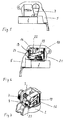
- Fig. 1 1 denotes a rocker arm detonator according to the invention for a hand grenade reproduced in an exploded view.
- the rocker arm detonator 1 contains a detonator head 2.
- This comprises a pivotably arranged firing pin 4 acted upon by a firing pin spring 3 and a safety bracket 5 on which the firing pin 4 is supported.
- the securing bracket 5 is in the same direction of rotation as the firing pin 4 from a starting position in which it is for example manually pressed in the direction of the detonator head 2 (cf. also the Figures 5 and 6 as well as the Figures 8 and 9 ), arranged pivotably into a firing pin release position (not shown).
- the firing pin spring 3 is not tensioned when the corresponding hand grenade is not in use, i.e. the firing pin 4 is supported on the safety bracket 5 in this case without pretensioning.
- the firing pin spring 3 is only tensioned when the hand grenade carrying the rocker arm detonator 1 is to be used.
- pivotable clamping lever 7 is arranged, which is non-rotatably connected to a clamping lever shaft 8 mounted in the detonator head 2.
- the firing pin spring 3 Arranged on this tensioning lever shaft 8 is the firing pin spring 3, designed as a cylindrical helical torsion spring (leg spring), the first leg 9 of which is connected to the tensioning lever shaft 8 and whose second leg 10 is connected to the firing pin 4, so that a rotation of the tensioning lever 7 is a rotation of the tensioning lever shaft 8 and thus the firing pin spring 3 is tensioned.
- leg spring cylindrical helical torsion spring
- the firing pin spring 3 is secured in this position by means of a safety device 11, so that when the tensioning lever 7 is released, the firing pin spring 3 does not automatically return to its relaxed state by turning the tensioning lever shaft 8 back.
- the safety bracket 5 carries a cam 12 ( Fig. 2 ), which is in a guide groove 13 of the clamping lever 7 ( Figs. 3 and 4 ) intervenes.
- This guide groove 13 has a first projection 14 and a second projection 25, which ensures that the clamping lever 7 can only be actuated into its armed position when the securing bracket 5 is also held in its starting position. Otherwise, the cam 12 of the securing bracket 5 would block the movement of the tensioning lever 7 after the tensioning lever 7 has been pivoted briefly.
- the clamping lever 7 can be pivoted further and, if the pressure of the securing bracket 5 (again) is too low, engages the second projection 25 in its armed position and, after the armed position has been reached, releases through a corresponding recess 15 on the edge the cam 12 of the safety bracket 5 free so that the safety bracket 5 can be pivoted into the firing pin release position (as soon as the hand of the user of the hand grenade releases the safety bracket).
- the securing device 11 comprises a disk-shaped locking wheel 16 which is connected to the tensioning lever shaft 8 in a rotationally fixed manner and which contains a second latching groove 17 on its outer circumference, and a locking arm 19 pivoted about an axis of rotation 18.
- the axis of rotation 18 of the locking arm 19 is parallel to the tensioning lever shaft 8, and the locking arm 19 has a latching element 20 at its end facing away from the axis of rotation 18.
- This locking element 20 is pressed by a pretensioned spring 21 against the outer circumference of the locking wheel 16, so that the locking element 20 when the clamping lever 7 is in focus - and thus the tensioned state of the firing pin spring 3 - into the second locking groove 17 of the Lock wheel 16 engages.
- a first locking groove 22 is arranged on the outer circumference of the locking wheel 16 such that in the rest position of the clamping lever 7 the locking element 20 of the locking arm 19 engages in the second locking groove 22 of the locking wheel 16 and thereby secures the clamping lever 7 in its rest position .
- the rocker arm detonator 1 comprises a relaxation element 23 End of the locking arm 19.
- the relaxation element 23 is moved downwards, for example, the latching element 20 of the locking arm 19 disengages from the second latching groove 17 of the locking wheel 16, and the tensioning lever 7 is pivoted back into its starting position by the pressure of the firing pin spring 3.
- a leg spring instead of a leg spring, a leaf spring can also be used as the firing pin spring, which is tensioned by a corresponding cam arranged on the tensioning lever shaft.
- a pressure element can also be used as a relaxation element, which presses the locking arm out of the latching groove of the locking arm.
Landscapes
- Engineering & Computer Science (AREA)
- General Engineering & Computer Science (AREA)
- Automotive Seat Belt Assembly (AREA)
- Emergency Lowering Means (AREA)
- Lock And Its Accessories (AREA)
Description
- Die Erfindung betrifft einen Kipphebelzünder mit einem Zünderkopf, der einen von einer Schlagbolzenfeder beaufschlagten, schwenkbar angeordneten Schlagbolzen umfasst, und mit einem Sicherungsbügel, der im selben Drehsinn wie der Schlagbolzen von einer Ausgangsposition, bei der er in Richtung auf den Zünderkopf gedrückt ist, in eine Schlagbolzen-Freigabeposition schwenkbar angeordnet ist.
- Derartige Kipphebelzünder sind beispielsweise aus der
DE-AS 1 289 765 bekannt und werden üblicherweise für Wurfkörper, insbesondere für Handgranaten, verwendet. Dabei erfolgt die Zündung des Kipphebelzünders durch das Vorschnellen eines durch eine Feder vorgespannten Schlagbolzens, der in gespanntem Zustand von dem Sicherungsbügel gehalten wird. Der Sicherungsbügel ist einseitig am Zünderkopf eingehängt und mittels eines entfernbaren Sicherheitssplints in seiner Ruheposition am Zünderkopf arretiert. - Weitere Kipphebel beschreiben die
BE 50 53 24 FR 625 278 FR 799 440 FR 2 432 153 FR 2 500 621 US4333401A sowieFR 601 185 CH 379 966 A5 FR 628 604 A FR 2 825 462 A1 DE 10 2010 021 685 B4 . - Nachteilig ist bei den bekannten Kipphebelzündern unter anderem, dass die Schlagbolzenfeder auch dann vorgespannt ist, wenn der Kipphebelzünder nicht bestimmungsgemäß verwendet wird, wenn also die den Kipphebelzünder verwendende Handgranate nicht im Gebrauch ist. Denn dadurch wird ein ungewolltes Auslösen des Zünders (etwa durch ein unbeabsichtigtes Ziehen des Sicherheitssplintes) wesentlich begünstigt.
- Der Erfindung liegt die Aufgabe zugrunde, einen Kipphebelzünder anzugeben, bei dem ein unbeabsichtigtes Zünden vor seinem bestimmungsgemäßen Einsatz sicher vermieden wird.
- Diese Aufgabe wird erfindungsgemäß durch die Merkmale des Anspruchs 1 gelöst. Weitere, besonders vorteilhafte Ausgestaltungen der Erfindung offenbaren die Unteransprüche.
- Die Erfindung beruht im Wesentlichen auf dem Gedanken, dass sich bei einem nicht im Gebrauch befindlichen Kipphebelzünder die Schlagbolzenfeder in ihrem ungespannten Zustand befinden sollte und durch einen separaten Spannhebel spannbar ist, sobald der den Kipphebelzünder enthaltende Wurfkörper bestimmungsgemäß eingesetzt wird (Unstored Energy Fuze Head).
- Hierzu ist an dem Zünderkopf des Kipphebelzünders der von einer Ruhe- in eine Scharfstellung betätigbare Spannhebel über eine Spannhebelwelle mit der Schlagbolzenfeder verbunden, derart, dass nur bei in seiner Ausgangsposition befindlichem Sicherungsbügel die Schlagbolzenfeder von ihrem ungespannten Zustand in ihren gespannten Zustand betätigbar und die Schlagbolzenfeder in ihrem gespannten Zustand mittels einer Sicherungseinrichtung arretierbar ist.
- Da sich die Schlagbolzenfeder bei dem nicht im Gebrauch befindlichen Kipphebelzünder in ihrem entspannten Zustand befindet, kann vorteilhafterweise bei dem erfindungsgemäßen Kipphebelzünder ein Sicherungssplint entfallen.
- Um sicherzustellen, dass die Schlagbolzenfeder nur spannbar ist, wenn sich der Sicherungsbügel in seiner Ausgangsposition befindet, hat es sich als zweckmäßig erwiesen, wenn der Sicherungsbügel einen Nocken trägt, der in eine Führungsnut des Spannhebels eingreift, derart, dass der Spannhebel nur dann in seine Scharfstellung betätigbar ist, wenn der Sicherungsbügel in seiner Ausgangsposition gehalten wird und dass die Führungsnut den Nocken in der Scharfstellung des Spannhebels freigibt, sodass der Sicherungsbügel in die Schlagbolzen-Freigabeposition schwenkbar ist.
- Bei der Schlagbolzenfeder kann es sich vorzugsweise um eine durch die Spannhebelwelle geführte Schenkelfeder handeln, deren erster Schenkel mit der Spannhebelwelle und deren zweiter Schenkel mit dem Schlagbolzen verbunden ist.
- Die Sicherungseinrichtung zur Sicherung der Schlagbolzenfeder in ihrer gespannten Position umfasst vorzugsweise ein mit der Spannhebelwelle drehfest verbundenes, scheibenförmiges Riegelrad, welches auf seinem äußeren Umfang mindestens eine erste Rastnut enthält, und einen um eine Drehachse schwenkbar angeordneten Verriegelungsarm, wobei die Drehachse des Verriegelungsarmes parallel zu der Spannhebelwelle angeordnet ist und der Verriegelungsarm an seinem der Drehachse abgewandten Ende ein Rastelement aufweist, das durch eine vorgespannte Feder gegen den äußeren Umfang des Riegelrades gedrückt wird, sodass das Rastelement beim Erreichen der Scharfstellung des Spannhebels - und damit des gespannten Zustandes der Schlagbolzenfeder - in die zweite Rastnut des Riegelrades eingreift.
- Vorteilhafterweise ist an dem äußeren Umfang des Riegelrades eine erste Rastnut angeordnet, derart, dass in der Ruhestellung des Spannhebels das Rastelement des Verriegelungsarmes in die erste Rastnut des Riegelrades eingreift und dadurch der Spannhebel in der Ruhestellung gesichert wird.
- Um die gespannte Schlagbolzenfeder auf einfache Weise wieder zu entspannen, wenn ein Einsatz des entsprechenden Wurfkörpers nicht mehr beabsichtigt ist, hat es sich als vorteilhaft erwiesen, wenn die Sicherungseinrichtung durch ein von außen betätigbares Entspannelement entsicherbar ist, sodass bei in seiner Ausgangsposition befindlichem Sicherungsbügel bei Betätigung des Entspannelementes die Schlagbolzenfeder wieder von ihrem gespannten in ihren ungespannten Zustand gelangt.
- Bei dem Entspannelement kann es sich um ein Druck- oder Schiebeelement handeln, welches bei seiner Betätigung auf das der Drehachse abgewandte Ende des Verriegelungsarmes wirkt, derart, dass das Rastelement des Verriegelungsarmes aus der Rastnut des Riegelrades gelangt und der Spannhebel durch den Druck der Schlagbolzenfeder von seiner Scharfstellung in seine Ruhestellung zurückgeschwenkt wird.
- Um das Entspannelement mit der Wurfhand, die den Sicherungsbügel in ihrer Ausgangsposition hält, entspannen zu können, hat es sich als vorteilhaft erwiesen, das Entspannelement durch eine Ausnehmung des Sicherungsbügels von außen betätigbar anzuordnen.
- Um also ein unbeabsichtigtes Zünden des Kipphebelzünders vor seiner bestimmungsgemäßen Verwendung sicher zu vermeiden, ist vorgesehen, dass sich bei dem nicht im Gebrauch befindlichen Kipphebelzünder die Schlagbolzenfeder in ihrem ungespannten Zustand befindet, und durch einen separaten Spannhebel spannbar ist, sobald der Kipphebelzünder bestimmungsgemäß eingesetzt werden soll.
- Weitere Einzelheiten und Vorteile der Erfindung ergeben sich aus dem folgenden, anhand von Figuren erläuterten Ausführungsbeispiel. Es zeigen:
- Fig. 1
- die Explosionsdarstellung eines erfindungsgemäßen Kipphebelzünders mit Sicherungsbügel und Spannhebel;
- Fig. 2
- die Seitenansicht des Sicherungsbügels des in
Fig. 1 dargestellten Kipphebelzünders aus der inFig. 1 mit II bezeichneten Richtung; - Fig. 3
- eine perspektivische Ansicht des Spannhebels des in
Fig. 1 dargestellten Kipphebelzünders; - Fig. 4
- eine Draufsicht auf den in
Fig. 3 dargestellten Spannhebel; - Fig. 5 und 6
- Seitenansichten des in
Fig. 1 dargestellten Kipphebelzünders, wobei sich die Schlagbolzenfeder in ihrem entspannten Zustand befindet; - Fig. 7
- eine perspektivische Ansicht des in
Fig. 1 dargestellten Kipphebelzünders mit entspannter Schlagbolzenfeder und unter Weglassung des Sicherungsbügels; -
Fig. 8-10 denFig. 5-7 entsprechenden Ansichten, wobei sich die Schlagbolzenfeder in ihrem gespannten Zustand befindet. - In
Fig. 1 ist mit 1 ein in Explosionsdarstellung wiedergegebener, erfindungsgemäßer Kipphebelzünder für eine Handgranate bezeichnet. Der Kipphebelzünder 1 enthält einen Zünderkopf 2. Dieser umfasst einen von einer Schlagbolzenfeder 3 beaufschlagten, schwenkbar angeordneten Schlagbolzen 4 und einen Sicherungsbügel 5, an dem sich der Schlagbolzen 4 abstützt. Der Sicherungsbügel 5 ist im selben Drehsinn wie der Schlagbolzen 4 von einer Ausgangsposition, bei der er beispielsweise manuell in Richtung auf den Zünderkopf 2 gedrückt wird (vgl. auch dieFig. 5 und 6 sowie dieFig. 8 und 9 ), in eine Schlagbolzen-Freigabeposition (nicht dargestellt) schwenkbar angeordnet. - Erfindungsgemäß ist nun vorgesehen, dass die Schlagbolzenfeder 3 bei Nichtbenutzung der entsprechenden Handgranate nicht gespannt ist, d.h. der Schlagbolzen 4 stützt sich in diesem Fall ohne Vorspannung an dem Sicherungsbügel 5 ab.
- Vielmehr erfolgt das Spannen der Schlagbolzenfeder 3 erst dann, wenn die den Kipphebelzünder 1 tragende Handgranate eingesetzt werden soll. Hierzu ist an der linken Au-βenseite 6 des Zünderkopfes 2 ein von einer Ruhestellung (
Fig. 5-7 ) in eine Scharfstellung (Fig. 8-10 ) schwenkbarer Spannhebel 7 angeordnet, der drehfest mit einer in dem Zünderkopf 2 gelagerten Spannhebelwelle 8 verbunden ist. Auf dieser Spannhebelwelle 8 ist die als zylindrische Schraubendrehfeder (Schenkelfeder) ausgebildete Schlagbolzenfeder 3 angeordnet, deren erster Schenkel 9 mit der Spannhebelwelle 8 und deren zweiter Schenkel 10 mit dem Schlagbolzen 4 verbunden ist, sodass eine Drehung des Spannhebels 7 eine Drehung der Spannhebelwelle 8 und damit ein Spannen der Schlagbolzenfeder 3 bewirkt. - Allerdings ist es zum Spannen der Schlagbolzenfeder 3 zwingend erforderlich, dass der Sicherungsbügel 5 gedrückt bleibt. Anderenfalls würde bei der Betätigung des Spannhebels 7 von seiner Ruhe- in seine Scharfstellung über die Schlagbolzenfeder 3 der Schlagbolzen 4 und damit auch der Sicherungsbügel 5 in Richtung auf einen Vorsprung 14 verschwenkt und arretiert werden, und die Schlagbolzenfeder 3 würde nicht auf die für den Zündvorgang erforderliche Vorspannung spannbar sein.
- Sobald der Spannhebel 7 bei gedrücktem Sicherungsbügel 5 in seine Scharfstellung geschwenkt ist, wird die Schlagbolzenfeder 3 in dieser Position mittels einer Sicherungseinrichtung 11 gesichert, sodass bei Loslassen des Spannhebels 7 die Schlagbolzenfeder 3 nicht automatisch durch Zurückdrehen der Spannhebelwelle 8 wieder in ihren entspannten Zustand gelangt.
- Um außerdem sicherzustellen, dass ein Vorschnellen des Schlagbolzens 4 erst möglich ist, wenn die Schlagbolzenfeder 3 eine für den Zündvorgang ausreichend hohe Spannung besitzt, der Spannhebel 7 sich also bereits in der Scharfstellung befindet, trägt der Sicherungsbügel 5 einen Nocken 12 (
Fig. 2 ), der in eine Führungsnut 13 des Spannhebels 7 (Fig. 3 und 4 ) eingreift. Diese Führungsnut 13 weist einen ersten Vorsprung 14 und einen zweiten Vorsprung 25 auf, der sicherstellt, dass der Spannhebel 7 nur dann in seine Scharfstellung betätigbar ist, wenn der Sicherungsbügel 5 auch in seiner Ausgangsposition gehalten wird. Anderenfalls würde der Nocken 12 des Sicherungsbügels 5 die Bewegung des Spannhebels 7 nach einem kurzen Verschwenken des Spannhebels 7 blockieren. - Nach Überwinden des Vorsprunges 14 durch Drücken des Sicherungsbügels 5 lässt sich der Spannhebel 7 weiter schwenken und rastet bei (erneut) zu geringem Druck des Sicherungsbügels 5 und den zweiten Vorsprung 25 in seine Scharfstellung ein und gibt nach Erreichen der Scharfstellung durch eine entsprechende randseitige Ausnehmung 15 den Nocken 12 des Sicherungsbügels 5 frei, sodass der Sicherungsbügel 5 in die Schlagbolzen-Freigabeposition schwenkbar ist (sobald die Hand des Verwenders der Handgranate den Sicherungsbügel loslässt).
- Die Sicherungseinrichtung 11 umfasst ein mit der Spannhebelwelle 8 drehfest verbundenes, scheibenförmiges Riegelrad 16, welches auf seinem äußeren Umfang eine zweite Rastnut 17 enthält, und einen um eine Drehachse 18 schwenkbar angeordneten Verriegelungsarm 19. Dabei ist die Drehachse 18 des Verriegelungsarmes 19 parallel zu der Spannhebelwelle 8 angeordnet, und der Verriegelungsarm 19 weist an seinem der Drehachse 18 abgewandten Ende ein Rastelement 20 auf. Dieses Rastelement 20 wird durch eine vorgespannte Feder 21 gegen den äußeren Umfang des Riegelrades 16 gedrückt, sodass das Rastelement 20 beim Erreichen der Scharfstellung des Spannhebels 7 - und damit des gespannten Zustandes der Schlagbolzenfeder 3 - in die zweite Rastnut 17 des Riegelrades 16 eingreift.
- Wie den
Fig. 1 ,6 ,7 ,9 und 10 entnehmbar ist, ist an dem äußeren Umfang des Riegelrades 16 eine erste Rastnut 22 angeordnet, derart, dass in der Ruhestellung des Spannhebels 7 das Rastelement 20 des Verriegelungsarmes 19 in die zweite Rastnut 22 des Riegelrades 16 eingreift und dadurch den Spannhebel 7 in seiner Ruhestellung sichert. - Um sicherzustellen, dass bei bereits gespannter Schlagbolzenfeder 3 (
Fig. 8-10 ) diese auf einfache Weise wieder entspannt werden kann, ohne dass die Gefahr einer Zündung der entsprechenden Handgranate besteht, umfasst der Kipphebelzünder 1 ein Entspannelement 23. Dieses ist durch eine Ausnehmung 24 des Sicherungsbügels 5 von außen betätigbar und wirkt dabei auf das der Drehachse 18 abgewandte Ende des Verriegelungsarmes 19. - Wird das Entspannelement 23 bei dem hier beschriebenen Ausführungsbeispiel beispielsweise nach unten verschoben, so gelangt das Rastelement 20 des Verriegelungsarmes 19 außer Eingriff mit der zweiten Rastnut 17 des Riegelrades 16, und der Spannhebel 7 wird durch den Druck der Schlagbolzenfeder 3 wieder in seine Ausgangsposition geschwenkt.
- Die Erfindung ist selbstverständlich nicht auf das vorstehend beschriebene Ausführungsbeispiel beschränkt. So kann statt einer Schenkelfeder beispielsweise auch eine Blattfeder als Schlagbolzenfeder verwendet werden, die durch einen entsprechenden auf der Spannhebelwelle angeordneten Nocken gespannt wird.
- Als Entspannelement kann beispielsweise statt eines Schiebers auch ein Druckelement verwendet werden, welches den Verriegelungsarm aus der Rastnut des Riegelarmes herausdrückt.
-
- 1
- Kipphebelzünder
- 2
- Zünderkopf
- 3
- Schlagbolzenfeder
- 4
- Schlagbolzen
- 5
- Sicherungsbügel
- 6
- Außenseite
- 7
- Spannhebel
- 8
- Spannhebelwelle
- 9
- erster Schenkel (Schlagbolzenfeder)
- 10
- zweiter Schenkel (Schlagbolzenfeder)
- 11
- Sicherungseinrichtung
- 12
- Nocken
- 13
- Führungsnut
- 14
- erster Vorsprung
- 15
- Ausnehmung
- 16
- Riegelrad
- 17
- zweite Rastnut
- 18
- Drehachse
- 19
- Verriegelungsarm
- 20
- Rastelement
- 21
- Feder
- 22
- erste Rastnut
- 23
- Entspannelement
- 24
- Ausnehmung
- 25
- zweiter Vorsprung
Claims (8)
- Kipphebelzünder mit einem Zünderkopf (2), der einen von einer Schlagbolzenfeder (3) beaufschlagten, schwenkbar angeordneten Schlagbolzen (4) umfasst, und mit einem Sicherungsbügel (5), der in eine Schlagbolzen-Freigabeposition schwenkbar angeordnet ist, dadurch gekennzeichnet, dass der Zünderkopf (2) einen von einer Ruhe- in eine Scharfstellung betätigbaren Spannhebel (7) umfasst, der über eine Spannhebelwelle (8) mit der Schlagbolzenfeder (3) verbunden ist, dass die Schlagbolzenfeder (3) von ihrem ungespannten Zustand in einen gespannten Zustand betätigbar und die Schlagbolzenfeder (3) in ihrem gespannten Zustand mittels einer Sicherungseinrichtung (11) arretierbar ist, wobei die Sicherungseinrichtung (11) ein mit der Spannhebelwelle (8) drehfest verbundenes, scheibenförmiges Riegelrad (16), welches auf seinem äußeren Umfang mindestens eine erste Rastnut (22) enthält, und einen um eine Drehachse (18) schwenkbar angeordneten Verriegelungsarm (19) umfasst, wobei die Drehachse (18) des Verriegelungsarmes (19) parallel zu der Spannhebelwelle (8) angeordnet ist und der Verriegelungsarm (19) an seinem der Drehachse (18) abgewandten Ende ein Rastelement (20) aufweist, das durch eine vorgespannte Feder (21) gegen den äußeren Umfang des Riegelrades (16) gedrückt wird, sodass das Rastelement (20) beim Erreichen der Scharfstellung des Spannhebels (7) - und damit des gespannten Zustandes der Schlagbolzenfeder (3) - in eine zweite Rastnut (17) des Riegelrades (16) eingreift.
- Kipphebelzünder nach Anspruch 1, dadurch gekennzeichnet, dass der Sicherungsbügel (5) einen Nocken (12) trägt, der in eine Führungsnut (13) des Spannhebels (7) eingreift, derart, dass der Spannhebel (7) nur dann in seine Scharfstellung betätigbar ist, wenn der Sicherungsbügel (5) in seiner Ausgangsposition gehalten wird, und dass der Spannhebel (7) den Nocken (12) beim Erreichen der Scharfstellung freigibt, sodass der Sicherungsbügel (5) in die Schlagbolzen-Freigabeposition schwenkbar ist.
- Kipphebelzünder nach einem der Ansprüche 1 oder 2, dadurch gekennzeichnet, dass es sich bei der Schlagbolzenfeder (3) um eine durch die Spannhebelwelle (8) geführte Schenkelfeder handelt, deren erster Schenkel (9) mit der Spannhebelwelle (8) und deren zweiter Schenkel (10) mit dem Schlagbolzen (4) verbunden ist.
- Kipphebelzünder nach einem der Ansprüche 1 bis 3, dadurch gekennzeichnet, dass an dem äußeren Umfang des Riegelrades (16) eine erste Rastnut (22) angeordnet ist, derart, dass in der Ruhestellung des Spannhebels (7) das Rastelement (20) des Verriegelungsarmes (19) in die erste Rastnut (22) des Riegelrades (16) eingreift und dadurch den Spannhebel (7) in seiner Ruhestellung sichert.
- Kipphebelzünder nach einem der Ansprüche 1 bis 4, dadurch gekennzeichnet, dass die Sicherungseinrichtung (11) durch ein von außen betätigbares Entspannelement (23) entsicherbar ist, sodass bei in seiner Ruheposition befindlichem Sicherungsbügel (5) bei Betätigung des Entspannelementes (23) die Schlagbolzenfeder (3) wieder von ihrem gespannten in ihren ungespannten Zustand gelangt.
- Kipphebelzünder nach einem der Ansprüche 1 bis 5, dadurch gekennzeichnet, dass es sich bei dem Entspannelement (23) um ein Druck- oder Schiebeelement handelt, welches bei seiner Betätigung auf das der Drehachse (18) abgewandte Ende des Verriegelungsarmes (19) wirkt, derart, dass das Rastelement (20) des Verriegelungsarmes (19) außer Eingriff mit der zweiten Rastnut (17) des Riegelrades (16) gelangt und der Spannhebel (7) durch den Druck der Schlagbolzenfeder (3) wieder in seine Ausgangsposition geschwenkt wird.
- Kipphebelzünder nach Anspruch 5 oder 6, dadurch gekennzeichnet, dass das Entspannelement (23) derart angeordnet ist, dass es durch eine Ausnehmung (24) des Sicherungsbügels (5) von außen betätigbar ist.
- Kipphebelzünder nach einem der Ansprüche 1 bis 7, dadurch gekennzeichnet, dass der Sicherungsbügel (5) im selben Drehsinn wie der Schlagbolzen (4) von einer Ausgangsposition, bei der er in Richtung auf den Zünderkopf (2) gedrückt ist, in die Schlagbolzen-Freigabeposition geschwenkt wird.
Priority Applications (4)
| Application Number | Priority Date | Filing Date | Title |
|---|---|---|---|
| HUE14166474A HUE057842T2 (hu) | 2014-04-29 | 2014-04-29 | Billenõkapcsolós gyújtó |
| ES14166474T ES2905130T3 (es) | 2014-04-29 | 2014-04-29 | Detonador de balancín |
| EP14166474.8A EP2940421B1 (de) | 2014-04-29 | 2014-04-29 | Kipphebelzünder |
| PL14166474T PL2940421T3 (pl) | 2014-04-29 | 2014-04-29 | Zapalnik z dźwignią wahliwą |
Applications Claiming Priority (1)
| Application Number | Priority Date | Filing Date | Title |
|---|---|---|---|
| EP14166474.8A EP2940421B1 (de) | 2014-04-29 | 2014-04-29 | Kipphebelzünder |
Publications (2)
| Publication Number | Publication Date |
|---|---|
| EP2940421A1 EP2940421A1 (de) | 2015-11-04 |
| EP2940421B1 true EP2940421B1 (de) | 2021-11-10 |
Family
ID=50588577
Family Applications (1)
| Application Number | Title | Priority Date | Filing Date |
|---|---|---|---|
| EP14166474.8A Active EP2940421B1 (de) | 2014-04-29 | 2014-04-29 | Kipphebelzünder |
Country Status (4)
| Country | Link |
|---|---|
| EP (1) | EP2940421B1 (de) |
| ES (1) | ES2905130T3 (de) |
| HU (1) | HUE057842T2 (de) |
| PL (1) | PL2940421T3 (de) |
Families Citing this family (2)
| Publication number | Priority date | Publication date | Assignee | Title |
|---|---|---|---|---|
| DE102017108938B4 (de) | 2017-04-26 | 2023-05-17 | Rheinmetall Waffe Munition Gmbh | Irritationskörper mit Mitteln zur Einstellung einer Wirkleistung |
| EP3410058B1 (de) | 2017-05-31 | 2024-04-10 | Rheinmetall Waffe Munition ARGES GmbH | Wirksystem mit wenigstens einem wirkkörper und wenigstens einer auslöseeinheit |
Citations (3)
| Publication number | Priority date | Publication date | Assignee | Title |
|---|---|---|---|---|
| US3498223A (en) * | 1967-06-30 | 1970-03-03 | Forsvarets Fabriksverk | Lever-controlled fuse for hand grenades |
| US4333401A (en) * | 1979-08-13 | 1982-06-08 | Charles M. Byers | Hand grenade |
| US8561540B1 (en) * | 2011-12-29 | 2013-10-22 | The United States Of America As Represented By The Secretary Of The Army | Rotating thumb safety fuze for a hand grenade and related methods of operation and assembly |
Family Cites Families (10)
| Publication number | Priority date | Publication date | Assignee | Title |
|---|---|---|---|---|
| FR601185A (de) | 1926-01-24 | |||
| FR625278A (fr) | 1926-03-08 | 1927-08-06 | Bouchon allumeur pour grenades | |
| FR628604A (fr) | 1926-04-14 | 1927-10-26 | Brault Et Comini | Perfectionnement aux grenades à levier |
| FR799440A (fr) | 1935-03-14 | 1936-06-12 | Perfectionnements aux bouchons-allumeurs pour grenades | |
| CH379966A (de) | 1960-12-28 | 1964-07-15 | Stamag Ag | Handgranate |
| DE1289765B (de) | 1965-11-24 | 1969-02-20 | Feistel Pyrotech Fab | Kipphebelzuender fuer Wurfkoerper |
| FR2432153A1 (fr) | 1978-07-28 | 1980-02-22 | Alsetex | Grenade a double interruption de chaine pyrotechnique |
| FR2500621A1 (fr) | 1981-02-20 | 1982-08-27 | France Etat | Bouchon allumeur pour grenade, a securite amelioree |
| FR2825462B1 (fr) | 2001-05-30 | 2003-09-26 | Dixi Microtechniques | Bouchon allumeur pour grenade a main |
| DE102010021685B4 (de) | 2010-05-27 | 2012-04-12 | Rheinmetall Waffe Munition Gmbh | Wiedersicherung für einen Kipphebelzünder |
-
2014
- 2014-04-29 EP EP14166474.8A patent/EP2940421B1/de active Active
- 2014-04-29 ES ES14166474T patent/ES2905130T3/es active Active
- 2014-04-29 PL PL14166474T patent/PL2940421T3/pl unknown
- 2014-04-29 HU HUE14166474A patent/HUE057842T2/hu unknown
Patent Citations (3)
| Publication number | Priority date | Publication date | Assignee | Title |
|---|---|---|---|---|
| US3498223A (en) * | 1967-06-30 | 1970-03-03 | Forsvarets Fabriksverk | Lever-controlled fuse for hand grenades |
| US4333401A (en) * | 1979-08-13 | 1982-06-08 | Charles M. Byers | Hand grenade |
| US8561540B1 (en) * | 2011-12-29 | 2013-10-22 | The United States Of America As Represented By The Secretary Of The Army | Rotating thumb safety fuze for a hand grenade and related methods of operation and assembly |
Also Published As
| Publication number | Publication date |
|---|---|
| EP2940421A1 (de) | 2015-11-04 |
| HUE057842T2 (hu) | 2022-06-28 |
| PL2940421T3 (pl) | 2022-04-04 |
| ES2905130T3 (es) | 2022-04-07 |
Similar Documents
| Publication | Publication Date | Title |
|---|---|---|
| EP2950033B1 (de) | Handfeuerwaffe und abzugssicherung hierfür | |
| EP2577219B1 (de) | Wiedersicherung für einen kipphebelzünder | |
| DE2643828B2 (de) | Zünder für drallarm zu verschießende Geschosse | |
| EP2940421B1 (de) | Kipphebelzünder | |
| EP3869142B1 (de) | Schusswaffe | |
| EP2228616B1 (de) | Abzugsmechanismus für Handfeuerwaffen | |
| EP2993090B1 (de) | Lenkradverriegelung | |
| DE102011013255A1 (de) | Entriegelungsvorrichtung | |
| DE1228965B (de) | Feststellvorrichtung fuer um eine Achse schwenkbare Teile von Lafetten | |
| DE10000177A1 (de) | Zündeinrichtung, insbesondere für eine Mörsergranate | |
| EP1397635B1 (de) | Zünder für eine handgranate | |
| EP3396301B1 (de) | Granate sowie verfahren zum betätigen derselben | |
| DE19633904C2 (de) | Vorderladerwaffe | |
| EP2474453B1 (de) | Fronthaubenscharnier | |
| DE1264298B (de) | Aufschlagzuender fuer drallfreie Geschosse | |
| DE3542209C2 (de) | ||
| AT243651B (de) | Sicherheitseinrichtung für Geschoßzünder | |
| DE884166C (de) | Uhrwerk fuer mechanische Zeitzuender | |
| DE4421353A1 (de) | Zünder für ein Bomblet | |
| DE112005002257T5 (de) | Sicherungs- und Entsicherungsvorrichtung eines Zünders für drallstabilisierte Munition vom Typ Rakete | |
| DE102022116662A1 (de) | Handwerfbarer Wirkkörper mit einem manuell ergreifbaren Gehäusekörper und Verfahren zum Bedienen eines Wirkkörpers | |
| DE102014016308A1 (de) | Gurtaufroller sowie Verfahren zur Steuerung einer Gurtbandauszugskraft in einem Gurtaufroller eines Fahrzeuginsassen-Rückhaltesystems | |
| DE1928761C3 (de) | Entsicherungsvorrichtung für die Zünderauslösung eines Sprengkörpers | |
| DE267504C (de) | ||
| AT12686U1 (de) | Betätigungseinrichtung |
Legal Events
| Date | Code | Title | Description |
|---|---|---|---|
| PUAI | Public reference made under article 153(3) epc to a published international application that has entered the european phase |
Free format text: ORIGINAL CODE: 0009012 |
|
| AK | Designated contracting states |
Kind code of ref document: A1 Designated state(s): AL AT BE BG CH CY CZ DE DK EE ES FI FR GB GR HR HU IE IS IT LI LT LU LV MC MK MT NL NO PL PT RO RS SE SI SK SM TR |
|
| AX | Request for extension of the european patent |
Extension state: BA ME |
|
| 17P | Request for examination filed |
Effective date: 20160427 |
|
| RBV | Designated contracting states (corrected) |
Designated state(s): AL AT BE BG CH CY CZ DE DK EE ES FI FR GB GR HR HU IE IS IT LI LT LU LV MC MK MT NL NO PL PT RO RS SE SI SK SM TR |
|
| STAA | Information on the status of an ep patent application or granted ep patent |
Free format text: STATUS: EXAMINATION IS IN PROGRESS |
|
| 17Q | First examination report despatched |
Effective date: 20171019 |
|
| STAA | Information on the status of an ep patent application or granted ep patent |
Free format text: STATUS: EXAMINATION IS IN PROGRESS |
|
| GRAP | Despatch of communication of intention to grant a patent |
Free format text: ORIGINAL CODE: EPIDOSNIGR1 |
|
| STAA | Information on the status of an ep patent application or granted ep patent |
Free format text: STATUS: GRANT OF PATENT IS INTENDED |
|
| INTG | Intention to grant announced |
Effective date: 20210622 |
|
| GRAS | Grant fee paid |
Free format text: ORIGINAL CODE: EPIDOSNIGR3 |
|
| GRAA | (expected) grant |
Free format text: ORIGINAL CODE: 0009210 |
|
| STAA | Information on the status of an ep patent application or granted ep patent |
Free format text: STATUS: THE PATENT HAS BEEN GRANTED |
|
| AK | Designated contracting states |
Kind code of ref document: B1 Designated state(s): AL AT BE BG CH CY CZ DE DK EE ES FI FR GB GR HR HU IE IS IT LI LT LU LV MC MK MT NL NO PL PT RO RS SE SI SK SM TR |
|
| REG | Reference to a national code |
Ref country code: GB Ref legal event code: FG4D Free format text: NOT ENGLISH |
|
| REG | Reference to a national code |
Ref country code: AT Ref legal event code: REF Ref document number: 1446460 Country of ref document: AT Kind code of ref document: T Effective date: 20211115 Ref country code: CH Ref legal event code: EP |
|
| REG | Reference to a national code |
Ref country code: DE Ref legal event code: R096 Ref document number: 502014015972 Country of ref document: DE |
|
| REG | Reference to a national code |
Ref country code: IE Ref legal event code: FG4D Free format text: LANGUAGE OF EP DOCUMENT: GERMAN |
|
| REG | Reference to a national code |
Ref country code: FI Ref legal event code: FGE |
|
| REG | Reference to a national code |
Ref country code: SE Ref legal event code: TRGR |
|
| REG | Reference to a national code |
Ref country code: NL Ref legal event code: FP |
|
| REG | Reference to a national code |
Ref country code: LT Ref legal event code: MG9D |
|
| REG | Reference to a national code |
Ref country code: ES Ref legal event code: FG2A Ref document number: 2905130 Country of ref document: ES Kind code of ref document: T3 Effective date: 20220407 |
|
| PG25 | Lapsed in a contracting state [announced via postgrant information from national office to epo] |
Ref country code: RS Free format text: LAPSE BECAUSE OF FAILURE TO SUBMIT A TRANSLATION OF THE DESCRIPTION OR TO PAY THE FEE WITHIN THE PRESCRIBED TIME-LIMIT Effective date: 20211110 Ref country code: LT Free format text: LAPSE BECAUSE OF FAILURE TO SUBMIT A TRANSLATION OF THE DESCRIPTION OR TO PAY THE FEE WITHIN THE PRESCRIBED TIME-LIMIT Effective date: 20211110 Ref country code: BG Free format text: LAPSE BECAUSE OF FAILURE TO SUBMIT A TRANSLATION OF THE DESCRIPTION OR TO PAY THE FEE WITHIN THE PRESCRIBED TIME-LIMIT Effective date: 20220210 |
|
| PG25 | Lapsed in a contracting state [announced via postgrant information from national office to epo] |
Ref country code: IS Free format text: LAPSE BECAUSE OF FAILURE TO SUBMIT A TRANSLATION OF THE DESCRIPTION OR TO PAY THE FEE WITHIN THE PRESCRIBED TIME-LIMIT Effective date: 20220310 Ref country code: PT Free format text: LAPSE BECAUSE OF FAILURE TO SUBMIT A TRANSLATION OF THE DESCRIPTION OR TO PAY THE FEE WITHIN THE PRESCRIBED TIME-LIMIT Effective date: 20220310 Ref country code: NO Free format text: LAPSE BECAUSE OF FAILURE TO SUBMIT A TRANSLATION OF THE DESCRIPTION OR TO PAY THE FEE WITHIN THE PRESCRIBED TIME-LIMIT Effective date: 20220210 Ref country code: LV Free format text: LAPSE BECAUSE OF FAILURE TO SUBMIT A TRANSLATION OF THE DESCRIPTION OR TO PAY THE FEE WITHIN THE PRESCRIBED TIME-LIMIT Effective date: 20211110 Ref country code: HR Free format text: LAPSE BECAUSE OF FAILURE TO SUBMIT A TRANSLATION OF THE DESCRIPTION OR TO PAY THE FEE WITHIN THE PRESCRIBED TIME-LIMIT Effective date: 20211110 Ref country code: GR Free format text: LAPSE BECAUSE OF FAILURE TO SUBMIT A TRANSLATION OF THE DESCRIPTION OR TO PAY THE FEE WITHIN THE PRESCRIBED TIME-LIMIT Effective date: 20220211 |
|
| REG | Reference to a national code |
Ref country code: HU Ref legal event code: AG4A Ref document number: E057842 Country of ref document: HU |
|
| PG25 | Lapsed in a contracting state [announced via postgrant information from national office to epo] |
Ref country code: SM Free format text: LAPSE BECAUSE OF FAILURE TO SUBMIT A TRANSLATION OF THE DESCRIPTION OR TO PAY THE FEE WITHIN THE PRESCRIBED TIME-LIMIT Effective date: 20211110 Ref country code: SK Free format text: LAPSE BECAUSE OF FAILURE TO SUBMIT A TRANSLATION OF THE DESCRIPTION OR TO PAY THE FEE WITHIN THE PRESCRIBED TIME-LIMIT Effective date: 20211110 Ref country code: RO Free format text: LAPSE BECAUSE OF FAILURE TO SUBMIT A TRANSLATION OF THE DESCRIPTION OR TO PAY THE FEE WITHIN THE PRESCRIBED TIME-LIMIT Effective date: 20211110 Ref country code: EE Free format text: LAPSE BECAUSE OF FAILURE TO SUBMIT A TRANSLATION OF THE DESCRIPTION OR TO PAY THE FEE WITHIN THE PRESCRIBED TIME-LIMIT Effective date: 20211110 Ref country code: DK Free format text: LAPSE BECAUSE OF FAILURE TO SUBMIT A TRANSLATION OF THE DESCRIPTION OR TO PAY THE FEE WITHIN THE PRESCRIBED TIME-LIMIT Effective date: 20211110 |
|
| REG | Reference to a national code |
Ref country code: DE Ref legal event code: R097 Ref document number: 502014015972 Country of ref document: DE |
|
| PLBE | No opposition filed within time limit |
Free format text: ORIGINAL CODE: 0009261 |
|
| STAA | Information on the status of an ep patent application or granted ep patent |
Free format text: STATUS: NO OPPOSITION FILED WITHIN TIME LIMIT |
|
| 26N | No opposition filed |
Effective date: 20220811 |
|
| PG25 | Lapsed in a contracting state [announced via postgrant information from national office to epo] |
Ref country code: AL Free format text: LAPSE BECAUSE OF FAILURE TO SUBMIT A TRANSLATION OF THE DESCRIPTION OR TO PAY THE FEE WITHIN THE PRESCRIBED TIME-LIMIT Effective date: 20211110 |
|
| PG25 | Lapsed in a contracting state [announced via postgrant information from national office to epo] |
Ref country code: SI Free format text: LAPSE BECAUSE OF FAILURE TO SUBMIT A TRANSLATION OF THE DESCRIPTION OR TO PAY THE FEE WITHIN THE PRESCRIBED TIME-LIMIT Effective date: 20211110 |
|
| REG | Reference to a national code |
Ref country code: BE Ref legal event code: MM Effective date: 20220430 |
|
| PG25 | Lapsed in a contracting state [announced via postgrant information from national office to epo] |
Ref country code: MC Free format text: LAPSE BECAUSE OF FAILURE TO SUBMIT A TRANSLATION OF THE DESCRIPTION OR TO PAY THE FEE WITHIN THE PRESCRIBED TIME-LIMIT Effective date: 20211110 Ref country code: LU Free format text: LAPSE BECAUSE OF NON-PAYMENT OF DUE FEES Effective date: 20220429 |
|
| PG25 | Lapsed in a contracting state [announced via postgrant information from national office to epo] |
Ref country code: BE Free format text: LAPSE BECAUSE OF NON-PAYMENT OF DUE FEES Effective date: 20220430 |
|
| PG25 | Lapsed in a contracting state [announced via postgrant information from national office to epo] |
Ref country code: IE Free format text: LAPSE BECAUSE OF NON-PAYMENT OF DUE FEES Effective date: 20220429 |
|
| PGFP | Annual fee paid to national office [announced via postgrant information from national office to epo] |
Ref country code: PL Payment date: 20230321 Year of fee payment: 10 |
|
| REG | Reference to a national code |
Ref country code: AT Ref legal event code: MM01 Ref document number: 1446460 Country of ref document: AT Kind code of ref document: T Effective date: 20220429 |
|
| PG25 | Lapsed in a contracting state [announced via postgrant information from national office to epo] |
Ref country code: AT Free format text: LAPSE BECAUSE OF NON-PAYMENT OF DUE FEES Effective date: 20220429 |
|
| PGFP | Annual fee paid to national office [announced via postgrant information from national office to epo] |
Ref country code: IT Payment date: 20230426 Year of fee payment: 10 Ref country code: FR Payment date: 20230424 Year of fee payment: 10 Ref country code: ES Payment date: 20230627 Year of fee payment: 10 Ref country code: DE Payment date: 20220620 Year of fee payment: 10 Ref country code: CZ Payment date: 20230425 Year of fee payment: 10 Ref country code: CH Payment date: 20230502 Year of fee payment: 10 |
|
| PGFP | Annual fee paid to national office [announced via postgrant information from national office to epo] |
Ref country code: SE Payment date: 20230420 Year of fee payment: 10 Ref country code: HU Payment date: 20230421 Year of fee payment: 10 Ref country code: FI Payment date: 20230419 Year of fee payment: 10 |
|
| PGFP | Annual fee paid to national office [announced via postgrant information from national office to epo] |
Ref country code: GB Payment date: 20230419 Year of fee payment: 10 |
|
| PG25 | Lapsed in a contracting state [announced via postgrant information from national office to epo] |
Ref country code: MK Free format text: LAPSE BECAUSE OF FAILURE TO SUBMIT A TRANSLATION OF THE DESCRIPTION OR TO PAY THE FEE WITHIN THE PRESCRIBED TIME-LIMIT Effective date: 20211110 Ref country code: CY Free format text: LAPSE BECAUSE OF FAILURE TO SUBMIT A TRANSLATION OF THE DESCRIPTION OR TO PAY THE FEE WITHIN THE PRESCRIBED TIME-LIMIT Effective date: 20211110 |
|
| PGFP | Annual fee paid to national office [announced via postgrant information from national office to epo] |
Ref country code: NL Payment date: 20240418 Year of fee payment: 11 |