EP2939954A1 - Einwurfsäule für eine unterflur-müllsammeleinrichtung sowie unterflur-müllsammeleinrichtung - Google Patents
Einwurfsäule für eine unterflur-müllsammeleinrichtung sowie unterflur-müllsammeleinrichtung Download PDFInfo
- Publication number
- EP2939954A1 EP2939954A1 EP15164589.2A EP15164589A EP2939954A1 EP 2939954 A1 EP2939954 A1 EP 2939954A1 EP 15164589 A EP15164589 A EP 15164589A EP 2939954 A1 EP2939954 A1 EP 2939954A1
- Authority
- EP
- European Patent Office
- Prior art keywords
- throw
- column
- elements
- collection device
- refuse
- Prior art date
- Legal status (The legal status is an assumption and is not a legal conclusion. Google has not performed a legal analysis and makes no representation as to the accuracy of the status listed.)
- Granted
Links
- 238000003780 insertion Methods 0.000 title description 10
- 230000037431 insertion Effects 0.000 title description 10
- 239000002699 waste material Substances 0.000 claims description 22
- 239000010813 municipal solid waste Substances 0.000 claims description 16
- 238000000034 method Methods 0.000 claims description 13
- 230000004913 activation Effects 0.000 claims description 12
- 230000003213 activating effect Effects 0.000 claims description 4
- 230000008878 coupling Effects 0.000 claims 1
- 238000010168 coupling process Methods 0.000 claims 1
- 238000005859 coupling reaction Methods 0.000 claims 1
- 238000010276 construction Methods 0.000 description 4
- 238000013461 design Methods 0.000 description 3
- 238000013519 translation Methods 0.000 description 3
- 238000004891 communication Methods 0.000 description 2
- 230000003749 cleanliness Effects 0.000 description 1
- 230000001419 dependent effect Effects 0.000 description 1
- 230000007613 environmental effect Effects 0.000 description 1
- 238000005429 filling process Methods 0.000 description 1
- 238000002347 injection Methods 0.000 description 1
- 239000007924 injection Substances 0.000 description 1
Images


Classifications
-
- B—PERFORMING OPERATIONS; TRANSPORTING
- B65—CONVEYING; PACKING; STORING; HANDLING THIN OR FILAMENTARY MATERIAL
- B65F—GATHERING OR REMOVAL OF DOMESTIC OR LIKE REFUSE
- B65F1/00—Refuse receptacles; Accessories therefor
- B65F1/10—Refuse receptacles; Accessories therefor with refuse filling means, e.g. air-locks
-
- B—PERFORMING OPERATIONS; TRANSPORTING
- B65—CONVEYING; PACKING; STORING; HANDLING THIN OR FILAMENTARY MATERIAL
- B65F—GATHERING OR REMOVAL OF DOMESTIC OR LIKE REFUSE
- B65F1/00—Refuse receptacles; Accessories therefor
- B65F1/14—Other constructional features; Accessories
- B65F1/1426—Housings, cabinets or enclosures for refuse receptacles
- B65F1/1447—Housings, cabinets or enclosures for refuse receptacles located underground
Definitions
- the present invention initially relates to a throw-in column for an underfill refuse collection device. Furthermore, the invention also relates to an underfloor refuse collection device and a method for filling an underfloor refuse collection device.
- underfloor refuse collection facilities have been developed in the past. These are underground or semi-underground waste systems. Such waste systems meet all requirements for cleanliness, aesthetics and environmental friendliness. They convince in particular by less disposal trips and the emptying especially in one-man operation.
- Underground refuse collection facilities are above ground from a throw-in column, which has at least one opening for garbage.
- a large receptacle is provided, which may have, for example, up to 5m 3 capacity.
- the receptacle is in communication with the throw-in column. Waste, which is thrown over the throw-in column, passes through this into the receptacle.
- the receptacle may be covered at its upper end with a cover plate.
- a cover plate Through the cover plate of the receptacle is completed upwards.
- the cover plate On the cover plate is then the throw-in column.
- the cover plate preferably has a filling opening, which cooperates with the throw-in column.
- Above ground is usually visible only the throw-in column, which has only a small footprint, and which can be designed in an attractive design. Furthermore, the cover plate of the receptacle can be visible. The actual storage of the waste takes place in the large, underground or at least semi-underground receptacle.
- the emptying of such underfloor waste collection device can be done for example by means of a crane.
- the underfloor refuse collection device has, for example, a gripping device that can be gripped by the crane.
- this gripping device is provided on the throw-in column, wherein this is not absolutely necessary.
- the throw-in column is then pulled out of the ground with the receiving container fastened therein.
- the receptacle can then be emptied into a garbage collection vehicle.
- optional safety platforms are used, which close the pit during the emptying process of the receptacle. After emptying the receptacle is sunk back into the ground, so that it is not visible in regular operation.
- the present invention has for its object to provide a throw-in column for an underground refuse collection device with improved properties. Furthermore, an underfloor refuse collection device equipped with such a throw-in column as well as a method for filling such an underfill refuse collection device should also be provided.
- the basic idea of the present invention consists in the fact that the throw-in column is designed such that it can be moved in and out of the receptacle. If no garbage is introduced into the underfloor refuse collection device via the throw-in column, the throw-in column is located inside the receptacle and preferably closes a filling opening located in the cover plate for the receptacle. If waste is introduced into the underfloor refuse collection device, the throw-in column is moved out of the receptacle in a special way for this purpose, the throw-in column, in the extended state, releasing or producing a throw-in opening for refuse. This means that the throw-in column can be moved in and out, preferably via a drive device, arranged in an underfill Müllsammeleiraum.
- a drop-in column for an underfill refuse collection device characterized in that the throw-in column is divided into two or more throw-in column members, in particular longitudinally split, that the two or more throw-in column members are movably disposed, and that the movable Injection column elements are provided such that they are capable of releasing or generating an insertion opening due to their movement.
- a throw-in column for an underfill refuse collection device which is characterized in that the throw-in column is designed to be retractable and extendable into / from the underfloor refuse collection device, in particular a receptacle of the underfloor refuse collection device.
- the present invention relates to a throw-in column for an underground refuse collection device.
- Such underfloor refuse collection device preferably consists above ground from the throw-in column, which has at least one waste dump.
- a large receptacle is provided, which may have, for example, up to 5m 3 capacity.
- Waste which is thrown over the throw-in column, passes through this into the receptacle.
- the receptacle is covered at its upper end with a cover plate. Through the cover plate of the receptacle is completed upwards. On the cover plate is then the throw-in column.
- the cover plate preferably has a filling opening, which cooperates with the throw-in column. Above ground is preferred only the throw-in column, which has only a small footprint, and which can be designed in an attractive design. Furthermore, the cover plate of the receptacle can be visible. The actual storage of the waste takes place in the large, underground or at least semi-underground receptacle.
- the throw-in column is designed in a special way, namely such that the throw-in column is divided into two or more throw-in column elements, in particular is split longitudinally.
- the throw-in column consists of exactly two throw-in column elements.
- the throw-in column is designed in several parts, wherein the individual parts represent the throw-in column elements. This means that the throw-in column, in particular in the longitudinal direction, is divided into the individual throw column elements.
- the two or more throw-in column elements are arranged to be movable.
- a suitable drive device is provided in particular, which will be described in greater detail below.
- the movable arrangement makes it possible, in particular, for the throw-in column elements to be moved into and out of the receptacle of the underfill collecting device, in particular in the manner already described above.
- the throw-in column elements are arranged to be movable independently of one another, or to be movable in a coupled manner. Preferred embodiments of this will be explained in more detail in the course of the description.
- the invention provides that the movable throw-in column elements, in particular via a corresponding drive means, are provided in such a way that they are capable of releasing or generating a throw-in opening due to their movement.
- a throw-in opening is preferably physically located in at least one of the throw-in column elements. By a corresponding movement, this throw-in opening is then released.
- no physical insertion opening is provided in the throw-in column. Rather, the insertion hole created by the movement of the throw-in column elements.
- the situation may occur that the throw-in column elements move apart, that is, away from one another, during movement, in particular during movement into a position in which the filling column is filled with refuse. whereby a gap arises between the throw-in column elements. This gap can then take over the function of an insertion opening or represent the insertion opening.
- the throw-in column In the initial state, the throw-in column is in a retracted position, for example.
- the throw-in column can in this case, in particular within the receptacle of the underfill refuse collection device, in particular such an underground refuse collection device, which has been described above, so that reference is made to the relevant information in full.
- a filling opening within the cover plate of the receptacle is then preferably closed. This can, as explained in more detail below, for example, by the throw-in column.
- the throw-in column Upon activation, the throw-in column is moved from the first retracted position to a second, extended position. In this second, extended position, the throw-in column is located outside of the receiving container, in particular outside the cover plate.
- the throw-in column releases a waste-disposal opening, or else such a throw-in opening is generated by means of the throw-in column elements.
- a waste-disposal opening may be provided within the throw-in column.
- the throw-in column forms such a throw-in opening.
- the throw-in column can in a preferred embodiment release an emptying opening via which the refuse in the throw-in column is emptied into the receptacle.
- the insertion opening and the discharge opening may be identical, depending on the configuration, or they may be different openings.
- the throw-in column elements may preferably be dish-shaped elements.
- a shell is understood in particular a flat structure that can be single or double (spatially) curved.
- throw-in column elements are simply curved shell elements, they preferably represent so-called cylindrical shells, which have a curved course in one direction over the longitudinal extent.
- each throw-in column element is designed in the form of a doubly curved shell, and that the doubly curved shell in particular has a shell surface with oppositely directed main curvatures.
- Such an embodiment of the throw-in column elements has the particular advantage that the throw-in column elements in the retracted state of the throw-in column do not protrude too far into the underfloor refuse collection device, for example in their receptacle, since the throw-in column elements are moved away laterally by the double curvature.
- a throw-in column designed in this way thus represents a very space-saving variant.
- the double-curved shell described above may be a so-called translation shell.
- a translation shell results from the movement of a plane curve (generatrix) along a second plane curve (guide curve) that is not in the plane of the generatrix.
- a shell preferably has a convex structure in plan view of the interior of the shell, in particular a guide curve with a convex profile.
- the double-curved shell may also be designed in the form of a hyperbolic paraboloid.
- a double-curved shell as described above initially has a first curvature which is formed by the generatrix and which initially gives the shell the shape of a cylindrical shell, which has a curved course in one direction over the longitudinal extent.
- the shell still has a second curvature, which is formed by the guide curve, wherein the curvature of the guide curve is directed differently than the curvature of the generatrix. In particular, this creates a shell surface with oppositely directed main curvatures.
- the throw-in column elements are arranged to be movable relative to each other in opposite directions. If the throw-in column elements are curved, it is preferably provided that the throw-in column elements are movable and running, arranged or formed in opposite directions, in particular in opposite directions on a circular path.
- each throw-in column element may be movable on its own and independently of the other throw-in column elements.
- the throw-in column elements coupled in their movement, that is linked, are arranged movable. This can be done for example via suitable gear constructions, guide elements and the like, as will be described in more detail below.
- the drive of the throw-in column elements can preferably take place via a drive device.
- the invention is not limited to specific types of drive devices. If the throw-in elements move in opposite directions, in particular in opposite directions on a circular path, this can be done for example by means of a gear construction, each throw column element, in particular on a curved wall or surface, at least one gear or gear segment or is formed as such a gear segment, wherein the Gears or gear segments of the two throw-column elements are opposite, and wherein the gears or Unroll gear segments.
- the actual drive can be designed, for example, as an electric drive.
- the throw-in column elements at a first, upper end which is preferably a front side of the throw-in column elements, a closing element functioning as a cover element, or are designed as such a cover element.
- the throw-in column elements at a second, lower end which is preferably an end face of the throw-in column elements, a closing element acting as a bottom element, or are formed as a bottom element. If the throw-in column elements are dish-shaped, the closing elements preferably represent a boundary on the end faces of the dish elements.
- the cover elements of the throw-in column elements form the upper end of the throw-in column.
- the cover elements can be designed so that they close the filling opening in the cover plate of the receptacle in the retracted state of the throw-in column. If the throw-in column elements are curved, the two floor elements may be apart so as to allow the emptying of the garbage in the throw-in column.
- the upper lid elements especially when the throw-in column elements are curved as described above, move apart.
- the floor elements move towards each other until they touch, so that the throw-in column is closed at the bottom.
- the garbage can be thrown into the throw-in column, wherein the two apart driven upper lid elements enable or form the throw-in. If the throw-in column then retracts again, the two floor elements move apart, and release the discharge opening so that the garbage in the throw-in column can enter the receptacle.
- the closing elements acting as floor elements at the lower end are not absolutely necessary and thus represent an optional feature.
- the throw-in column elements can be open at the bottom. Only the upper end elements in the form of cover elements are preferably provided, since in the retracted state of the throw-in column the filling opening located in the cover plate is closed. If the throw-in column is in the extended state and the throw-in opening is present, refuse can easily be filled into the receptacle indefinitely.
- the floor elements are preferably provided.
- the throw-in column When the throw-in column is in the extended position, especially when the throw-in column elements are curved, the throw-in column is closed down by the bottom elements so that a space-limited chamber is available for the introduction of refuse. Only when by the movement of the throw-in column elements, during which the throw-in column is retracted, the opening provided by the throw-in elements opening is closed, open bottom elements, so that in a corresponding way a discharge opening is released and the refuse portion located in the throw-in column is emptied into the receptacle.
- Such an embodiment may be advantageous, for example, if the amount of waste to be introduced per loading operation is to be limited, for example, if a fee is to be charged per loading operation.
- an in-ground refuse collection device comprising a receptacle for receiving refuse, and a cover plate closing the receptacle upwardly, wherein a refuse filling hole is provided in the cover plate, and further comprising a garbage disposable column , which cooperates with the filling opening in the cover plate.
- the underfloor refuse collection device is characterized in that the throw-in column retractable and extendable in the receptacle, that the throw-in column is divided into two or more throw-in column members, in particular longitudinally split, that the two or more throw-in column members are movably arranged, and that the movable throw-in column members are provided so as to be able to due to their Movement to release or create a slot.
- the underfill refuse collection device according to the invention is thus characterized in particular by a throw-in column according to the invention, so that reference is made in full to the above statements on the throw-in column with respect to their design and mode of operation to avoid repetition at this point.
- the underfloor refuse collection device is characterized in particular by the fact that the throw-in column can be moved or moved by means of a drive device between a first position in which filling of the throw-in column with refuse takes place and a second position in which emptying of the throw-in column takes place in the receptacle becomes.
- the underfloor refuse collection device preferably has a drive device for moving at least one throw-in column element.
- the drive device has a motor device, by means of which the throw-in column elements can be moved.
- an electric motor is preferably used.
- the drive device preferably has guide elements, for example in the form of rails or the like, along which the throw-in column elements can be moved in a directed manner. This can be realized in other embodiment also via corresponding gear constructions.
- the invention is not limited to particular types of drive means.
- the drive device has a device in order to couple the throw-in column elements in their movement. This may be, for example, as already described above gear constructions.
- the throw-in column by means of the drive means between a first position in which a filling of the throw-in column is carried out with waste, and a second position in which an emptying of the throw-in column takes place in the receptacle, be moved or moved.
- the throw-in column is provided such that it is able to close the filling opening of the cover plate in the retracted state.
- the throw-in column is preferably provided in such a way that it is able to provide an opening for waste in the extended state.
- an activation unit for activating the throw-in column in particular for activating the drive device of the throw-in column, can be provided.
- This may be, for example, an activation column.
- the activation can be done, for example, by entering a code, or with the aid of a chip card.
- a method for refilling an underfill refuse collection device, in particular an underfill refuse collection device according to the invention as described above, with refuse, in particular with a refuse portion, wherein a refuse portion constitutes in particular a quantitatively limited amount of refuse.
- the waste is introduced by means of a throw-in column, in particular a throw-in column according to the invention as described above, into a receptacle of the underfloor refuse collection device.
- the method is characterized in that the throw-in column is moved, in particular by means of a drive device, into a position in which a filling of the throw-in column with waste takes place.
- the throw-in column is moved, in particular by means of a drive device, between a first position in which filling of the throw-in column with refuse occurs, and a second position in which emptying of the throw-in column takes place in the receptacle of the underfill refuse collection device ,
- the throw-in column at least temporarily closes a filling opening in a cover plate of the underfloor refuse collection device, which takes place in particular in the second position described above.
- an underfill collection device 10 which has a large receptacle 11, which is embedded in the ground. At the top, the receptacle 11 is closed by a cover plate 12. In the cover plate 12 is a filling opening 13, through which the garbage actually in can reach the receptacle 11. The filling opening 13 cooperates with a throw-in column 20, which can be retracted into the receptacle 11 and moved out of this, which is realized by a drive device, not shown. The activation of such a movement process takes place via an activation device 14, which can be controlled, for example, by means of a code card or the like.
- the throw-in column 20 is split longitudinally into two throw-in column elements 21 and 24, the throw-in column elements 21, 24 being designed as dish elements with double curvature. These are preferably translational dishes.
- a translation shell is formed, as in particular in FIG. 1 represented by the movement of a plane curve, the generatrix 27, along a second plane curve, the guide curve 28, wherein the guide curve 28 is not in the plane of the generatrix 27.
- Such a shell preferably has a convex structure, in particular a guide curve 28 with a convex profile, when the shell interior is viewed from above.
- Such a double-curved shell initially has a first curvature which is formed by the generatrix 27 and which initially gives the shell the shape of a cylindrical shell which has a curved course over the longitudinal extent L of the throw-in column 20.
- the shell still has a second curvature, which is formed by the guide curve 28, wherein the curvature of the guide curve 28 is directed differently than the curvature of the generatrix 27. This results in a shell surface with oppositely directed main curvatures.
- the throw-in column 20, or the drive means of the throw-in column 20 is activated.
- the throw-in column 20 is in a retracted position.
- the throw-in column 20 is in this case within the receptacle 11 of the underground refuse collection device 10th
- the filling opening 13 within the cover plate 12 of the receptacle 11 is then closed. This is done by the cover elements 22, 25 of the throw-in column elements 21, 24th
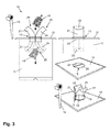
- the throw-in column 20 Upon activation, the throw-in column 20 is moved or moved from the first, retracted position to a second, extended position, which in FIG. 1 and in a corresponding manner in FIG. 3 is shown. In this second, extended position, the throw-in column 20 is located outside of the receptacle 11, in particular outside the cover plate 12. In the extended position, the throw-in column elements 21, 24, the throw-in column 20, which move apart due to the curvature, release a waste opening 29 for refuse, or else such an insertion opening 29 is generated by means of the throw-in column elements 21, 24.
- the throw-in column elements 21, 24 of the throw-in column 20 are again moved into the retracted position within the receptacle 11 into it.
- the throw-in column elements 21, 24 release a discharge opening 30 in a preferred embodiment, via which the refuse in the throw-in column 20 is emptied into the receptacle 11 in the form of the refuse bag 40
- the cover elements 22, 25 of the throw-in column elements 21, 24 form the upper end of the throw-in column 20.
- the cover elements 22, 25 are designed so that they in the retracted state of the throw-in column 20 the Close filling opening 13 in the cover plate 12 of the receptacle 11. If the throw-in column elements 21, 24 are curved, the two bottom elements 23, 26 may be apart in this state, so that they allow the emptying of the waste disposed in the throw-in column 20.
- the floor elements 23, 26 move towards each other until they touch, so that the throw-in column 20 is closed at the bottom.
- the garbage here in the form of the garbage bag 40, be thrown into the throw-in column 20, wherein the two apart driven upper lid members 22, 25 enable the insertion opening 29 or generate. If the throw-in column 20 is then retracted again, the two floor elements 23, 26 move apart, and release the discharge opening 30 so that the refuse in the throw-in column 20 can enter the receptacle 11.
Landscapes
- Engineering & Computer Science (AREA)
- Mechanical Engineering (AREA)
- Refuse Collection And Transfer (AREA)
Abstract
Description
- Die vorliegende Erfindung betrifft zunächst eine Einwurfsäule für eine Unterflur-Müllsammeleinrichtung. Weiterhin betrifft die Erfindung auch eine Unterflur-Müllsammeleinrichtung sowie ein verfahren zum Befüllen einer Unterflur-Müllsammeleinrichtung.
- Große Abfallmengen im urbanen Umfeld sind eine logistische und architektonische Herausforderung. Aus diesem Grund sind in der Vergangenheit so genannte Unterflur-Müllsammeleinrichtungen entwickelt worden. Hierbei handelt es sich um unterirdische oder semi-unterirdische Abfallsysteme. Derartige Abfallsysteme erfüllen alle Anforderungen an Sauberkeit, Ästhetik und Umweltfreundlichkeit. Sie überzeugen insbesondere durch weniger Entsorgungsfahrten und die Entleerung insbesondere im 1-Mann-Betrieb.
- Unterflur-Müllsammeleinrichtungen bestehen oberirdisch aus einer Einwurfsäule, welche wenigstens eine Einwurföffnung für Müll aufweist. Unterirdisch, oder zumindest semi-unterirdisch ist ein großer Aufnahmebehälter vorgesehen, der beispielsweise bis zu 5m3 Fassungsvermögen haben kann. An seinem oberen Ende steht der Aufnahmebehälter mit der Einwurfsäule in Verbindung. Müll, der über die Einwurfsäule eingeworfen wird, gelangt durch diese in den Aufnahmebehälter hinein.
- Beispielsweise kann der Aufnahmebehälter an seinem oberen Ende mit einer Abdeckplatte abgedeckt sein. Durch die Abdeckplatte wird der Aufnahmebehälter nach oben abgeschlossen. Auf der Abdeckplatte befindet sich dann die Einwurfsäule. Die Abdeckplatte weist bevorzugt eine Einfüllöffnung auf, die mit der Einwurfsäule zusammenwirkt.
- Oberirdisch sichtbar ist in der Regel nur die Einwurfsäule, die nur einen geringen Platzbedarf hat, und die in einem ansprechenden Design ausgebildet sein kann. Weiterhin kann auch die Abdeckplatte des Aufnahmebehälters sichtbar sein. Die eigentliche Lagerung des Mülls erfolgt in dem großen, unterirdischen oder zumindest semi-unterirdischen Aufnahmebehälter.
- Die Entleerung einer solchen Unterflur-Müllsammeleinrichtung kann beispielsweise mittels eines Krans erfolgen. Dazu verfügt die Unterflur-Müllsammeleinrichtung beispielsweise über eine Greifeinrichtung, die vom Kran gegriffen werden kann. Insbesondere ist vorgesehen, dass diese Greifeinrichtung an der Einwurfsäule vorgesehen ist, wobei dies nicht zwingend erforderlich ist. Mittels des Krans wird dann die Einwurfsäule mit dem darin befestigten Aufnahmebehälter aus dem Boden herausgezogen. Der Aufnahmebehälter kann anschließend in ein Müll-Sammelfahrzeug entleert werden. Damit es während des Entleerungsvorgangs, bei dem sich der Aufnahmebehälter folglich nicht in der dafür vorgesehenen Grube befindet, nicht zu Unfällen kommt, werden optional Sicherheits-Plattformen verwendet, die die Grube während des Entleerungsvorgangs des Aufnahmebehälters verschließen. Nach erfolgter Entleerung wird der Aufnahmebehälter wieder im Boden versenkt, so dass er im regulären Betrieb nicht sichtbar ist.
- Der vorliegenden Erfindung liegt die Aufgabe zugrunde, eine Einwurfsäule für eine Unterflur-Müllsammeleinrichtung mit verbesserten Eigenschaften bereitzustellen. Weiterhin sollen auch eine mit einer solchen Einwurfsäule ausgestattete Unterflur-Müllsammeleinrichtung sowie ein verfahren zum Befüllen einer solchen Unterflur-Müllsammeleinrichtung bereitgestellt werden.
- Diese Aufgabe wird erfindungsgemäß gelöst durch die Einwurfsäule mit den Merkmalen gemäß dem unabhängigen Patentanspruch 1, durch die Unterflur-Müllsammeleinrichtung mit den Merkmalen gemäß dem unabhängigen Patentanspruch 7 sowie durch das Verfahren zum Befüllen einer Unterflur-Müllsammeleinrichtung mit den Merkmalen gemäß dem unabhängigen Patentanspruch 15. Weitere Merkmale und Details der Erfindung ergeben sich aus den Unteransprüchen, der Beschreibung sowie den Zeichnungen. Dabei gelten Merkmale und Details, die im Zusammenhang mit der erfindungsgemäßen Einwurfsäule beschrieben sind, vollumfänglich auch im Zusammenhang mit der erfindungsgemäßen Unterflur-Müllsammeleinrichtung, und umgekehrt, so dass hinsichtlich der Offenbarung wechselseitig vollinhaltlich Bezug genommen und verwiesen wird. Weiterhin gelten Merkmale und Details, die im Zusammenhang mit der erfindungsgemäßen Einwurfsäule sowie der erfindungsgemäßen Unterflur-Müllsammeleinrichtung beschrieben sind, vollumfänglich auch im Zusammenhang mit dem erfindungsgemäßen Verfahren, und umgekehrt, so dass auch hinsichtlich dieser Offenbarung wechselseitig vollinhaltlich Bezug genommen und verwiesen wird.
- Der grundlegende Gedanke der vorliegenden Erfindung besteht nun darin, dass die Einwurfsäule derart ausgebildet ist, dass sie in den Aufnahmebehälter ein- und ausgefahren werden kann. Sofern in die Unterflur-Müllsammeleinrichtung über die Einwurfsäule kein Müll eingebracht wird, befindet sich die Einwurfsäule innerhalb des Aufnahmebehälters und verschließt bevorzugt eine in der Abdeckplatte für den Aufnahmebehälter befindliche Einfüllöffnung. Wenn Müll in die Unterflur-Müllsammeleinrichtung eingebracht wird, wird hierzu die Einwurfsäule in besonderer Weise aus dem Aufnahmebehälter herausgefahren, wobei die Einwurfsäule im ausgefahren Zustand eine Einwurföffnung für Müll freigibt oder erzeugt. Das bedeutet, dass die Einwurfsäule einfahrbar und ausfahrbar, vorzugsweise über eine Antriebseinrichtung, in einer Unterflur-Müllsammeleirichtung angeordnet ist.
- Gemäß dem ersten Aspekt der vorliegenden Patentanmeldung wird eine Einwurfsäule für eine Unterflur-Müllsammeleinrichtung bereitgestellt, die dadurch gekennzeichnet ist, dass die Einwurfsäule in zwei oder mehr Einwurfsäulenelemente unterteilt, insbesondere längsgeteilt ist, dass die zwei oder mehr Einwurfsäulenelemente beweglich angeordnet sind, und dass die beweglichen Einwurfsäulenelemente derart bereitgestellt sind, dass sie in der Lage sind, aufgrund ihrer Bewegung eine Einwurföffnung freizugeben oder zu erzeugen.
- Bereitgestellt wird somit insbesondere eine Einwurfsäule für eine Unterflur-Müllsammeleinrichtung, die dadurch gekennzeichnet ist, dass die Einwurfsäule einfahrbar und ausfahrbar in das /aus der Unterflur-Müllsammeleinrichtung, insbesondere einem Aufnahmebehälter der Unterflur-Müllsammeleinrichtung, ausgebildet ist.
- Gemäß dem ersten Aspekt betrifft die vorliegende Erfindung eine Einwurfsäule für eine Unterflur-Müllsammeleinrichtung. Eine solche Unterflur-Müllsammeleinrichtung besteht bevorzugt oberirdisch aus der Einwurfsäule, welche wenigstens eine Einwurföffnung für Müll aufweist. Unterirdisch, oder zumindest semi-unterirdisch ist ein großer Aufnahmebehälter vorgesehen, der beispielsweise bis zu 5m3 Fassungsvermögen haben kann. An seinem oberen Ende steht der Aufnahmebehälter mit der Einwurfsäule in Verbindung. Müll, der über die Einwurfsäule eingeworfen wird, gelangt durch diese in den Aufnahmebehälter hinein. Bevorzugt ist der Aufnahmebehälter an seinem oberen Ende mit einer Abdeckplatte abgedeckt. Durch die Abdeckplatte wird der Aufnahmebehälter nach oben abgeschlossen. Auf der Abdeckplatte befindet sich dann die Einwurfsäule. Die Abdeckplatte weist bevorzugt eine Einfüllöffnung auf, die mit der Einwurfsäule zusammenwirkt. Oberirdisch sichtbar ist bevorzugt nur die Einwurfsäule, die nur einen geringen Platzbedarf hat, und die in einem ansprechenden Design ausgebildet sein kann. Weiterhin kann auch die Abdeckplatte des Aufnahmebehälters sichtbar sein. Die eigentliche Lagerung des Mülls erfolgt in dem großen, unterirdischen oder zumindest semi-unterirdischen Aufnahmebehälter.
- Erfindungsgemäß ist die Einwurfsäule in besonderer Weise ausgestaltet, nämlich derart, dass die Einwurfsäule in zwei oder mehr Einwurfsäulenelemente unterteilt, insbesondere längsgeteilt ist. In einer bevorzugten Ausführungsform besteht die Einwurfsäule aus genau zwei Einwurfsäulenelementen. Erfindungsgemäß ist vorgesehen, dass die Einwurfsäule mehrteilig ausgebildet ist, wobei die einzelnen Teile die Einwurfsäulenelemente darstellen. Das bedeutet, dass die Einwurfsäule, insbesondere in deren Längsrichtung, in die einzelnen Einwurfsäulenelemente unterteilt ist.
- Erfindungsgemäß ist weiterhin vorgesehen, dass die zwei oder mehr Einwurfsäulenelemente beweglich angeordnet sind. Hierzu ist insbesondere eine geeignete Antriebseinrichtung vorgesehen, die weiter unten in größerem Detail beschrieben wird. Durch die bewegliche Anordnung wird es insbesondere möglich, dass die Einwurfsäulenelemente, insbesondere in der wie oben schon beschriebenen Weise, in den Aufnahmebehälter der Unterflur-Müllsammeleinrichtung eingefahren und aus diesem herausgefahren werden beziehungsweise werden können. Je nach Ausgestaltung kann vorgesehen sein, dass die Einwurfsäulenelemente unabhängig voneinander beweglich, oder aber gekoppelt beweglich angeordnet sind. Bevorzugte Ausführungsbeispiele hierzu werden im weiteren Verlauf der Beschreibung näher erläutert.
- Schließlich ist erfindungsgemäß vorgesehen, dass die beweglichen Einwurfsäulenelemente, insbesondere über eine entsprechende Antriebseinrichtung, derart bereitgestellt sind, dass sie in der Lage sind, aufgrund ihrer Bewegung eine Einwurföffnung freizugeben oder zu erzeugen. Im erstgenannten Fall befindet sich eine Einwurföffnung bevorzugt körperlich in wenigstens einem der Einwurfsäulenelemente. Durch eine entsprechende Bewegung wird diese Einwurföffnung dann freigegeben. Im letztgenannten Fall ist in der Einwurfsäule keine körperliche Einwurföffnung vorgesehen. Vielmehr entsteht die Einwurföffnung durch die Bewegung der Einwurfsäulenelemente. Wenn sich diese in geeigneter Weise gerichtet bewegen, kann beispielsweise die Situation auftreten, dass sich die Einwurfsäulenelemente während der Bewegung, insbesondere während der Bewegung in eine Position, in der eine Befüllung der Einwurfsäule mit Müll erfolgt, auseinander, das heißt voneinander weg, bewegen, wodurch ein Spalt zwischen den Einwurfsäulenelementen entsteht. Dieser Spalt kann dann die Funktion einer Einwurföffnung übernehmen beziehungsweise die Einwurföffnung darstellen.
- Die grundlegende Funktionsweise der Einwurfsäule sowie des Verfahrens, wie eine Befüllung einer Unterflur-Müllsammeleinrichtung über die Einwurfsäule erfolgt, ist insbesondere wie folgt:
- Über eine Aktivierungseinrichtung, beispielsweise eine Aktivierungssäule, die weiter unten noch näher erläutert ist, wird die Einwurfsäule, beziehungsweise die Antriebseinrichtung der Einwurfsäule, aktiviert.
- Im Ausgangszustand befindet sich die Einwurfsäule beispielsweise in einer eingefahrenen Position. Die Einwurfsäule kann sich in diesem Fall insbesondere innerhalb des Aufnahmebehälters der Unterflur-Müllsammeleinrichtung, insbesondere einer solchen Unterflur-Müllsammeleinrichtung, die eingangs beschrieben wurde, so dass auf die entsprechenden Informationen vollinhaltlich Bezug genommen wird, befinden. Eine Einfüllöffnung innerhalb der Abdeckplatte des Aufnahmebehälters ist dann bevorzugt verschlossen. Dies kann, wie weiter unten näher erläutert ist, beispielsweise durch die Einwurfsäule erfolgen. Bei einer Aktivierung wird die Einwurfsäule aus der ersten eingefahrenen Position in eine zweite, ausgefahrene Position verfahren. In dieser zweiten, ausgefahrenen Position befindet sich die Einwurfsäule außerhalb des Aufnahmebehälters, insbesondere außerhalb der Abdeckplatte. In der ausgefahren Position gibt die Einwurfsäule eine Einwurföffnung für Müll frei, oder aber es wird mittels der Einwurfsäulenelemente eine solche Einwurföffnung erzeugt. Beispielsweise kann eine solche Einwurföffnung innerhalb der Einwurfsäule vorgesehen sein. Oder aber die Einwurfsäule bildet eine derartige Einwurföffnung. Nach erfolgter Beladung der Einwurfsäule mit Müll wird die Einwurfsäule wieder in die eingefahrene Position innerhalb des Aufnahmebehälters hinein gefahren. Dabei kann die Einwurfsäule in einer bevorzugten Ausführungsform eine Entleerungsöffnung freigeben, über die der in der Einwurfsäule befindliche Müll in den Aufnahmebehälter entleert wird. Einwurföffnung und Entleerungsöffnung können je nach Ausgestaltung identisch sein, oder aber es handelt sich um unterschiedliche Öffnungen.
- Bei den Einwurfsäulenelementen kann es sich bevorzugt um schalenförmige Elemente handeln.
- Unter einer Schale wird dabei insbesondere ein flächiges Tragwerk verstanden, das einfach oder doppelt (räumlich) gekrümmt sein kann.
- Wenn es sich bei den Einwurfsäulenelementen um einfach gekrümmte Schalenelemente handelt, stellen diese bevorzugt so genannte Zylinderschalen dar, welche über die Längsausdehnung einen in einer Richtung gekrümmten Verlauf haben.
- In einer bevorzugten Ausgestaltung ist vorgesehen, dass jedes Einwurfsäulenelement in Form einer zweifach gekrümmten Schale ausgebildet ist, und dass die zweifach gekrümmte Schale insbesondere eine Schalenfläche mit gegensinnig gerichteten Hauptkrümmungen aufweist. Eine solche Ausgestaltung der Einwurfsäulenelemente hat insbesondere den Vorteil, dass die Einwurfsäulenelemente im eingefahrenen Zustand der Einwurfsäule nicht zu weit in die Unterflur-Müllsammeleinrichtung, beispielsweise in deren Aufnahmebehälter, hineinragen, da durch die doppelte Krümmung die Einwurfsäulenelemente beim Einfahren seitlich wegbewegt werden. Eine derart ausgestaltete Einwurfsäule stellt somit eine sehr platzsparende Variante dar.
- Insbesondere kann es sich bei der wie vorstehende beschriebenen doppelt gekrümmten Schale um eine so genannte Translationsschale handeln. Eine solche Translationsschale entsteht durch die Bewegung einer ebenen Kurve (Erzeugende) längs einer zweiten ebenen Kurve (Leitkurve), die nicht in der Ebene der Erzeugenden liegt. Eine solche Schale hat bei Draufsicht auf das Schaleninnere bevorzugt eine konvexe Struktur, insbesondere eine Leitkurve mit einem konvexen Verlauf. In anderer Ausgestaltung kann die doppelt gekrümmte Schale auch in Form eines hyperbolischen Paraboloids ausgebildet sein.
- Eine wie vorstehend beschriebene doppelt gekrümmte Schale weist zunächst eine erste Krümmung auf, die durch die Erzeugende gebildet wird und die der Schale zunächst die Form einer Zylinderschale verleiht, welche über die Längsausdehnung einen in eine Richtung gekrümmten Verlauf hat. Zusätzlich weist die Schale noch eine zweite Krümmung auf, die durch die Leitkurve gebildet wird, wobei die Krümmung der Leitkurve anders gerichtet ist als die Krümmung der Erzeugenden. Insbesondere entsteht dadurch eine Schalenfläche mit gegensinnig gerichteten Hauptkrümmungen.
- In weiterer Ausgestaltung ist bevorzugt vorgesehen, dass die Einwurfsäulenelemente in Bezug zueinander gegensinnig beweglich angeordnet sind. Wenn die Einwurfsäulenelemente gekrümmt ausgebildet sind, ist bevorzugt vorgesehen, dass die Einwurfsäulenelemente gegensinnig beweglich, insbesondere gegensinnig auf einer Kreisbahn beweglich und laufend, angeordnet oder ausgebildet sind.
- Je nach Ausgestaltung kann vorgesehen sein, dass jedes Einwurfsäulenelement für sich alleine und unabhängig von den anderen Einwurfsäulenelementen beweglich ist. In bevorzugter Ausgestaltung ist vorgesehen, dass die Einwurfsäulenelemente in ihrer Bewegung gekoppelt, das heißt verknüpft, beweglich angeordnet sind. Dies kann beispielsweise über geeignete Zahnradkonstruktionen, Führungselemente und dergleichen erfolgen, wie weiter unten in größerem Detail beschrieben wird.
- Bevorzugt kann der Antrieb der Einwurfsäulenelemente über eine Antriebseinrichtung erfolgen. Dabei ist die Erfindung nicht auf bestimmte Typen von Antriebseinrichtungen beschränkt. Wenn sich die Einwurfsäulenelemente gegensinnig, insbesondere gegensinnig auf einer Kreisbahn bewegen, kann dies beispielsweise mittels einer Zahnradkonstruktion erfolgen, wobei jedes Einwurfsäulenelement, insbesondere an einer gekrümmten Wand oder Oberfläche, wenigstens ein Zahnrad oder Zahnradsegment aufweist oder als ein solches Zahnradsegment ausgebildet ist, wobei sich die Zahnräder oder Zahnradsegmente der beiden Einwurfsäulenelemente gegenüberliegen, und wobei die Zahnräder oder Zahnradsegmente aufeinander abrollen. Der eigentliche Antrieb kann beispielsweise als elektrischer Antrieb ausgebildet sein.
- In bevorzugter Ausgestaltung weisen die Einwurfsäulenelemente an einem ersten, oberen Ende, bei dem es sich bevorzugt um eine Stirnseite der Einwurfsäulenelemente handelt, ein als Deckelelement fungierendes Abschlusselement auf, oder sind als ein solches Deckelelement ausgebildet. Alternativ oder zusätzlich weisen die Einwurfsäulenelemente an einem zweiten, unteren Ende, bei dem es sich bevorzugt um eine Stirnseite der Einwurfsäulenelemente handelt, ein als Bodenelement fungierendes Abschlusselement auf, oder sind als Bodenelement ausgebildet. Wenn die Einwurfsäulenelemente schalenförmig ausgebildet sind, stellen die Abschlusselemente bevorzugt eine Begrenzung an den Stirnseiten der Schalenelemente dar.
- Die Deckelelemente der Einwurfsäulenelemente bilden den oberen Abschluss der Einwurfsäule. Die Deckelelemente können dabei so ausgebildet sein, dass sie im eingefahrenen Zustand der Einwurfsäule die Einfüllöffnung in der Abdeckplatte des Aufnahmebehälters verschließen. Wenn die Einwurfsäulenelemente gekrümmt sind, können die beiden Bodenelemente auseinander liegen, so dass sie die Entleerung des in der Einwurfsäule befindlichen Mülls ermöglichen.
- Wenn die Einwurfsäule in die Befüllungsposition ausgefahren wird, bewegen sich die oberen Deckelelemente, insbesondere dann, wenn die Einwurfsäulenelemente wie oben beschrieben gekrümmt ausgebildet sind, auseinander. Die Bodenelemente bewegen sich aufeinander zu, bis sie sich berühren, so dass die Einwurfsäule am Boden geschlossen ist. Nun kann der Müll in die Einwurfsäule eingeworfen werden, wobei die beiden auseinander gefahrenen oberen Deckelelemente die Einwurföffnung freigeben oder bilden. Wird die Einwurfsäule danach wieder eingefahren, bewegen sich die beiden Bodenelemente auseinander, und geben die Entleerungsöffnung frei, so dass der in der Einwurfsäule befindliche Müll in den Aufnahmebehälter gelangen kann.
- Die am unteren Ende als Bodenelemente fungierenden Abschlusselemente sind nicht unbedingt erforderlich und stellen somit ein optionales Merkmal dar. Im einfachsten Fall können die Einwurfsäulenelemente nach unten offen sein. Lediglich die oberen Abschlusselemente in Form von Deckelelementen sind bevorzugt vorgesehen, da hierüber im eingefahrenen Zustand der Einwurfsäule die in der Abdeckplatte befindliche Einfüllöffnung verschlossen ist. Wenn sich die Einwurfsäule im ausgefahrenen Zustand befindet und die Einwurföffnung vorhanden ist, kann Müll auf einfache Weise unbegrenzt in den Aufnahmebehälter eingefüllt werden.
- Es kann aber auch gewollt sein, dass die Menge des einzuwerfenden Mülls portioniert und begrenzt wird. In diesem Fall werden bevorzugt die Bodenelemente vorgesehen. Wenn sich die Einwurfsäule in der ausgefahrenen Position befindet, ist, insbesondere wenn die Einwurfsäulenelemente gekrümmt sind, die Einwurfsäule durch die Bodenelemente nach unten abgeschlossen, so dass eine raummäßig begrenzte Kammer zur Einführung von Müll bereitsteht. Erst wenn durch die Bewegung der Einwurfsäulenelemente, während der die Einwurfsäule eingefahren wird, die durch die Einwurfsäulenelemente bereitgestellte Einwurföffnung geschlossen wird, öffnen sich Bodenelemente, so dass in entsprechender Weise eine Entleerungsöffnung freigegeben wird und die in der Einwurfsäule befindliche Müllportion in den Aufnahmebehälter entleert wird. Eine solche Ausgestaltung kann beispielsweise von Vorteil sein, wenn die einzuführende Müllmenge pro Beladevorgang begrenzt werden soll, etwa wenn pro Beladevorgang eine Gebühr abgerechnet werden soll.
- Gemäß einem zweiten Aspekt der Erfindung wird eine Unterflur-Müllsammeleinrichtung bereitgestellt, aufweisend einen Aufnahmebehälter zur Aufnahme von Müll, sowie eine Abdeckplatte, welche den Aufnahmebehälter nach oben abschließt, wobei in der Abdeckplatte eine Einfüllöffnung für Müll vorgesehen ist, sowie weiterhin aufweisend eine Einwurfsäule für Müll, welche mit der Einfüllöffnung in der Abdeckplatte zusammenwirkt. Die Unterflur-Müllsammeleinrichtung ist dadurch gekennzeichnet, dass die Einwurfsäule einfahrbar und ausfahrbar in dem Aufnahmebehälter angeordnet ist, dass die Einwurfsäule in zwei oder mehr Einwurfsäulenelemente unterteilt, insbesondere längsgeteilt ist, dass die zwei oder mehr Einwurfsäulenelemente beweglich angeordnet sind, und dass die beweglichen Einwurfsäulenelemente derart bereitgestellt sind, dass sie in der Lage sind, aufgrund ihrer Bewegung eine Einwurföffnung freizugeben oder zu erzeugen.
- Die erfindungsgemäße Unterflur-Müllsammeleinrichtung zeichnet sich somit insbesondere durch eine erfindungsgemäße Einwurfsäule aus, so dass hinsichtlich deren Ausgestaltung und Funktionsweise zur Vermeidung von Wiederholungen an dieser Stelle vollinhaltlich auf die vorstehenden Ausführungen zur Einwurfsäule Bezug genommen und verwiesen wird.
- Die Unterflur-Müllsammeleinrichtung ist insbesondere dadurch gekennzeichnet, dass die Einwurfsäule mittels einer Antriebseinrichtung zwischen einer ersten Position, in der eine Befüllung der Einwurfsäule mit Müll erfolgt, und einer zweiten Position, in der eine Entleerung der Einwurfsäule in den Aufnahmebehälter erfolgt, verfahrbar ist oder verfahren wird.
- Bevorzugt weist die Unterflur-Müllsammeleinrichtung eine Antriebseinrichtung zur Bewegung von wenigstens einem Einwurfsäulenelement auf. Zunächst weist die Antriebseinrichtung eine Motoreinrichtung auf, mittels derer die Einwurfsäulenelemente verfahren werden können. Hierbei kommt bevorzug ein elektrischer Motor zum Einsatz. Es sind aber auch hydraulische oder pneumatische Antriebsmöglichkeiten denkbar. Beispielsweise könnte die Einwurfsäule auch rein mechanisch angetrieben werden, beispielsweise über eine Seilwinde mit Kurbel. In weiterer Ausgestaltung weist die Antriebseinrichtung bevorzugt Führungselemente, beispielsweise in Form von Schienen oder dergleichen auf, entlang derer die Einwurfsäulenelemente gerichtet verfahren werden können. Dies lässt sich in anderer Ausgestaltung auch über entsprechende Zahnradkonstruktionen realisieren. Die Erfindung ist nicht auf bestimmte Typen von Antriebseinrichtungen beschränkt. In weiterer Ausgestaltung weist die Antriebseinrichtung eine Einrichtung auf, um die Einwurfsäulenelemente in deren Bewegung zu koppeln. Hierbei kann es sich beispielsweise um wie weiter oben bereits geschilderte Zahnradkonstruktionen handeln.
- Bevorzugt kann die Einwurfsäule mittels der Antriebseinrichtung zwischen einer ersten Position, in der eine Befüllung der Einwurfsäule mit Müll erfolgt, und einer zweiten Position, in der eine Entleerung der Einwurfsäule in den Aufnahmebehälter erfolgt, verfahrbar sein oder verfahren werden.
- Bevorzugt ist die Einwurfsäule derart bereitgestellt, dass sie in der Lage ist, im eingefahrenen Zustand die Einfüllöffnung der Abdeckplatte zu verschließen. Alternativ oder zusätzlich ist die Einwurfsäule bevorzugt derart bereitgestellt, dass sie in der Lage ist, im ausgefahrenen Zustand eine Einwurföffnung für Müll bereitzustellen.
- In weiterer Ausgestaltung kann eine Aktivierungseinheit zum Aktivieren der Einwurfsäule, insbesondere zum Aktivieren der Antriebseinrichtung der Einwurfsäule, vorgesehen sein. Hierbei kann es sich beispielsweise um eine Aktivierungssäule handeln. Die Aktivierung kann beispielsweise mittels Eingabe eines Codes, oder unter Zuhilfenahme einer Chipkarte, erfolgen.
- Gemäß einem dritten Aspekt der vorliegenden Erfindung wird ein Verfahren zum Befüllen einer Unterflur-Müllsammeleinrichtung, insbesondere einer wie vorstehend beschriebenen erfindungsgemäßen Unterflur-Müllsammeleinrichtung, mit Müll, insbesondere mit einer Müllportion bereitgestellt, wobei eine Müllportion insbesondere eine mengenmäßig begrenzte Müllmenge darstellt. Dabei wird der Müll mittels einer Einwurfsäule, insbesondere einer wie vorstehend beschriebenen erfindungsgemäßen Einwurfsäule, in einen Aufnahmebehälter der Unterflur-Müllsammeleinrichtung eingebracht. Aus diesem Grund wird bezüglich der Ausgestaltung und Funktionsweise des Verfahrens vollumfänglich auch auf die vorstehenden Ausführungen zur erfindungsgemäßen Unterflur-Müllsammeleinrichtung sowie zur erfindungsgemäßen Einwurfsäule Bezug genommen und verwiesen. Erfindungsgemäß ist das Verfahren dadurch gekennzeichnet, dass die Einwurfsäule, insbesondere mittels einer Antriebseinrichtung, in eine Position, in der eine Befüllung der Einwurfsäule mit Müll erfolgt, verfahren wird.
- Bevorzugt ist vorgesehen, dass die Einwurfsäule, insbesondere mittels einer Antriebseinrichtung, zwischen einer ersten Position, in der eine Befüllung der Einwurfsäule mit Müll erfolgt, und einer zweiten Position, in der eine Entleerung der Einwurfsäule in den Aufnahmebehälter der Unterflur-Müllsammeleinrichtung erfolgt, verfahren wird.
- Bevorzugt ist vorgesehen, dass die Einwurfsäule eine Einfüllöffnung in einer Abdeckplatte der Unterflur-Müllsammeleirichtung zumindest zeitweilig verschließt, was insbesondere in der vorstehend beschriebenen zweiten Position erfolgt.
- Die Erfindung wird nun anhand eines Ausführungsbeispiels unter Bezugnahme auf die beiliegenden Zeichnungen näher erläutert. Es zeigen
- Figur 1
- in mehreren Darstellungen eine Unterflur-Müllsammeleinrichtung, bei der sich die Einwurfsäule, die aus zwei gekrümmten Einwurfsäulenelementen gebildet ist, im eingefahrenen Zustand befindet;
- Figur 2
- in mehreren Darstellungen die Unterflur-Müllsammeleinrichtung, bei der sich die Einwurfsäule im ausgefahrenen Zustand befindet; und
- Figur 3
- in mehreren Darstellungen, wie ein Befüllvorgang der Unterflur-Müllsammeleinrichtung erfolgt.
- In den Figuren ist eine Unterflur-Müllsammeleinrichtung 10 dargestellt, welche einen großen Aufnahmebehälter 11 aufweist, der im Boden eingelassen ist. Nach oben wird der Aufnahmebehälter 11 durch eine Abdeckplatte 12 abgeschlossen. In der Abdeckplatte 12 befindet sich eine Einfüllöffnung 13, über die der Müll tatsächlich in den Aufnahmebehälter 11 gelangen kann. Die Einfüllöffnung 13 wirkt mit einer Einwurfsäule 20 zusammen, die in den Aufnahmebehälter 11 eingefahren und aus diesem herausgefahren werden kann, was durch eine nicht dargestellte Antriebseinrichtung realisiert ist. Die Aktivierung eines solchen Verfahrvorgangs erfolgt über eine Aktivierungseinrichtung 14, die beispielsweise mittels einer Codekarte oder dergleichen gesteuert werden kann.
- Die Einwurfsäule 20 ist in zwei Einwurfsäulenelemente 21 und 24 längsgeteilt, wobei die Einwurfsäulenelemente 21, 24 als Schalenelemente mit doppelter Krümmung ausgebildet sind. Bevorzugt handelt es sich hierbei um Translationsschalen. Eine solche Translationsschale entsteht, wie insbesondere in
Figur 1 dargestellt ist, durch die Bewegung einer ebenen Kurve, der Erzeugenden 27, längs einer zweiten ebenen Kurve, der Leitkurve 28, wobei die Leitkurve 28 nicht in der Ebene der Erzeugenden 27 liegt. Eine solche Schale hat bei Draufsicht auf das Schaleninnere bevorzugt eine konvexe Struktur, insbesondere eine Leitkurve 28 mit einem konvexen Verlauf. - Eine solche doppelt gekrümmte Schale weist zunächst eine erste Krümmung auf, die durch die Erzeugende 27 gebildet wird und die der Schale zunächst die Form einer Zylinderschale verleiht, welche über die Längsausdehnung L der Einwurfsäule 20 einen gekrümmten Verlauf hat. Zusätzlich weist die Schale noch eine zweite Krümmung auf, die durch die Leitkurve 28 gebildet wird, wobei die Krümmung der Leitkurve 28 anders gerichtet ist als die Krümmung der Erzeugenden 27. Dadurch entsteht eine Schalenfläche mit gegensinnig gerichteten Hauptkrümmungen.
- Sowohl am oberen Ende als auch am unteren Ende sind die Einwurfsäulenelemente 21, 24 durch Abschlusselemente begrenzt, die jeweils in Form von Deckelelementen 22, 25 und Bodenelementen 23, 26 ausgebildet sind.
- Nachfolgend werden die Funktionsweise der Unterflur-Müllsammeleinrichtung 10 sowie ein Verfahren zum Befüllen der Unterflur-Müllsammeleinrichtung 10 mit Müll beschrieben.
- Über die Aktivierungseinrichtung 14 wird die Einwurfsäule 20, beziehungsweise die Antriebseinrichtung der Einwurfsäule 20, aktiviert.
- Im Ausgangszustand, der in
Figur 2 und in entsprechender Weise inFigur 3 dargestellt ist, befindet sich die Einwurfsäule 20 in einer eingefahrenen Position. Die Einwurfsäule 20 befindet sich in diesem Fall innerhalb des Aufnahmebehälters 11 der Unterflur-Müllsammeleinrichtung 10. - Die Einfüllöffnung 13 innerhalb der Abdeckplatte 12 des Aufnahmebehälters 11 ist dann verschlossen. Dies erfolgt durch die Deckelelemente 22, 25 der Einwurfsäulenelemente 21, 24.
- Bei einer Aktivierung wird die Einwurfsäule 20 aus der ersten, eingefahrenen Position in eine zweite, ausgefahrene Position verfahren beziehungsweise bewegt, die in
Figur 1 und in entsprechender Weise inFigur 3 dargestellt ist. In dieser zweiten, ausgefahrenen Position befindet sich die Einwurfsäule 20 außerhalb des Aufnahmebehälters 11, insbesondere außerhalb der Abdeckplatte 12. In der ausgefahren Position geben die Einwurfsäulenelemente 21, 24, der Einwurfsäule 20, die aufgrund der Krümmung auseinanderfahren, eine Einwurföffnung 29 für Müll frei, oder aber es wird mittels der Einwurfsäulenelemente 21, 24 eine solche Einwurföffnung 29 erzeugt. - Nach erfolgter Beladung der Einwurfsäule 20 mit Müll, hier in Form eines Müllsacks 40, werden die Einwurfsäulenelemente 21, 24 der Einwurfsäule 20 wieder in die eingefahrene Position innerhalb des Aufnahmebehälters 11 hinein gefahren. Dabei geben die Einwurfsäulenelemente 21, 24 in einer bevorzugten Ausführungsform eine Entleerungsöffnung 30 frei, über die der in der Einwurfsäule 20 befindliche Müll in Form des Müllsacks 40 in den Aufnahmebehälter 11 entleert wird
- Die Deckelelemente 22, 25 der Einwurfsäulenelemente 21, 24 bilden den oberen Abschluss der Einwurfsäule 20. Die Deckelelemente 22, 25 sind dabei so ausgebildet, dass sie im eingefahrenen Zustand der Einwurfsäule 20 die Einfüllöffnung 13 in der Abdeckplatte 12 des Aufnahmebehälters 11 verschließen. Wenn die Einwurfsäulenelemente 21, 24 gekrümmt sind, können die beiden Bodenelemente 23, 26 in diesem Zustand auseinander liegen, so dass sie die Entleerung des in der Einwurfsäule 20 befindlichen Mülls ermöglichen.
- Wenn die Einwurfsäule 20 in die Befüllungsposition ausgefahren wird, bewegen sich die oberen Deckelelemente 22, 25, insbesondere dann, wenn die Einwurfsäulenelemente 21, 24 wie oben beschrieben gekrümmt ausgebildet sind, auseinander. Die Bodenelemente 23, 26 bewegen sich aufeinander zu, bis sie sich berühren, so dass die Einwurfsäule 20 am Boden geschlossen ist. Nun kann der Müll, hier in Form des Müllsacks 40, in die Einwurfsäule 20 eingeworfen werden, wobei die beiden auseinander gefahrenen oberen Deckelelemente 22, 25 die Einwurföffnung 29 freigeben beziehungsweise erzeugen. Wird die Einwurfsäule 20 danach wieder eingefahren, bewegen sich die beiden Bodenelemente 23, 26 auseinander, und geben die Entleerungsöffnung 30 frei, so dass der in der Einwurfsäule 20 befindliche Müll in den Aufnahmebehälter 11 gelangen kann.
-
- 10
- Unterflur-Müllsammeleinrichtung
- 11
- Aufnahmebehälter
- 12
- Abdeckplatte
- 13
- Einfüllöffnung
- 14
- Aktivierungseinrichtung
- 20
- Einwurfsäule
- 21
- Einwurfsäulenelement
- 22
- Deckelelement
- 23
- Bodenelement
- 24
- Einwurfsäulenelement
- 25
- Deckelelement
- 26
- Bodenelement
- 27
- Erzeugende
- 28
- Leitkurve
- 29
- Einwurföffnung
- 30
- Entleerungsöffnung
- 40
- Müllsack
- L
- Längsausdehnung der Einwurfsäule
Claims (15)
- Einwurfsäule (20) für eine Unterflur-Müllsammeleinrichtung (10), dadurch gekennzeichnet, dass die Einwurfsäule (20) in zwei oder mehr Einwurfsäulenelemente (21, 24) unterteilt, insbesondere längsgeteilt ist, dass die zwei oder mehr Einwurfsäulenelemente (21, 24) beweglich angeordnet sind, und dass die beweglichen Einwurfsäulenelemente (21, 24) derart bereitgestellt sind, dass sie in der Lage sind, aufgrund ihrer Bewegung eine Einwurföffnung (29) freizugeben oder zu erzeugen.
- Einwurfsäule nach Anspruch 1, dadurch gekennzeichnet, dass die Einwurfsäulenelemente (21, 24) schalenförmig ausgebildet sind.
- Einwurfsäule nach Anspruch 2, dadurch gekennzeichnet, dass jedes Einwurfsäulenelement (21, 24) in Form einer zweifach gekrümmten Schale ausgebildet ist und dass die zweifach gekrümmte Schale insbesondere eine Schalenfläche mit gegensinnig gerichteten Hauptkrümmungen (27, 28) aufweist.
- Einwurfsäule nach einem der Ansprüche 1 bis 3, dadurch gekennzeichnet, dass die Einwurfsäulenelemente (21, 24) in Bezug zueinander gegensinnig beweglich angeordnet sind.
- Einwurfsäule nach einem der Ansprüche 1 bis 4, dadurch gekennzeichnet, dass die Einwurfsäulenelemente (21, 24) in ihrer Bewegung gekoppelt beweglich angeordnet sind.
- Einwurfsäule nach einem der Ansprüche 1 bis 5, dadurch gekennzeichnet, dass die Einwurfsäulenelemente (21, 24) an einem ersten, oberen Ende ein als Deckelelement (22, 25) fungierendes Abschlusselement aufweisen oder als Deckelelement (22, 25) ausgebildet sind und/oder dass die Einwurfsäulenelemente (21, 24) an einem zweiten, unteren Ende ein als Bodenelement (23, 26) fungierendes Abschlusselement aufweisen oder als Bodenelement (23, 26) ausgebildet sind.
- Unterflur-Müllsammeleinrichtung (10), aufweisend einen Aufnahmebehälter (11) zur Aufnahme von Müll (40), sowie eine Abdeckplatte (12), welche den Aufnahmebehälter (11) nach oben abschließt, wobei in der Abdeckplatte (12) eine Einfüllöffnung (13) für Müll vorgesehen ist, sowie weiterhin aufweisend eine Einwurfsäule (20) für Müll, welche mit der Einfüllöffnung (13) in der Abdeckplatte (12) zusammenwirkt, dadurch gekennzeichnet, dass die Einwurfsäule (20) einfahrbar und ausfahrbar in dem Aufnahmebehälter (11) angeordnet ist, dass die Einwurfsäule (20) in zwei oder mehr Einwurfsäulenelemente (21, 24) unterteilt, insbesondere längsgeteilt ist, dass die zwei oder mehr Einwurfsäulenelemente (21, 24) beweglich angeordnet sind, und dass die beweglichen Einwurfsäulenelemente (21, 24) derart bereitgestellt sind, dass sie in der Lage sind, aufgrund ihrer Bewegung eine Einwurföffnung (29) freizugeben oder zu erzeugen.
- Unterflur-Müllsammeleinrichtung nach Anspruch 7, dadurch gekennzeichnet, dass die Einwurfsäule (20) nach einem der Ansprüche 2 bis 6 ausgebildet ist.
- Unterflur-Müllsammeleinrichtung nach Anspruch 7 oder 8, dadurch gekennzeichnet, dass diese eine Antriebseinrichtung zur Bewegung von wenigstens einem Einwurfsäulenelement (21, 24) aufweist.
- Unterflur-Müllsammeleinrichtung nach Anspruch 9, dadurch gekennzeichnet,
dass die Antriebseinrichtung eine Einrichtung aufweist, um die Einwurfsäulenelemente (21, 24) in deren Bewegung zu koppeln. - Unterflur-Müllsammeleinrichtung nach einem der Ansprüche 7 bis 10, dadurch gekennzeichnet, dass die Einwurfsäule (20) derart bereitgestellt ist, dass sie in der Lage ist, im eingefahrenen Zustand die Einfüllöffnung (13) der Abdeckplatte (12) zu verschließen.
- Unterflur-Müllsammeleinrichtung nach einem der Ansprüche 7 bis 11, dadurch gekennzeichnet, dass die Einwurfsäule (20) derart bereitgestellt ist, dass sie in der Lage ist, im ausgefahrenen Zustand eine Einwurföffnung (29) für Müll bereitzustellen.
- Unterflur-Müllsammeleinrichtung nach einem der Ansprüche 7 bis 12, dadurch gekennzeichnet, dass die Einwurfsäule (20) derart bereitgestellt ist, dass sie in der Lage ist, im eingefahrenen Zustand eine Entleerungsöffnung (30) für Müll bereitzustellen.
- Unterflur-Müllsammeleinrichtung nach einem der Ansprüche 7 bis 13, dadurch gekennzeichnet, dass diese eine Aktivierungseinrichtung (14) zum Aktivieren der Einwurfsäule (20), insbesondere zum Aktivieren der Antriebseinrichtung, aufweist.
- Verfahren zum Befüllen einer Unterflur-Müllsammeleinrichtung (10), insbesondere einer Unterflur-Müllsammeleinrichtung (10) nach einem der Ansprüche 7 bis 14, mit Müll, wobei der Müll mittels einer Einwurfsäule (20), insbesondere einer Einwurfsäule (20) nach einem der Ansprüche 1 bis 6, in einen Aufnahmebehälter (11) der Unterflur-Müllsammeleinrichtung (10) eingebracht wird, dadurch gekennzeichnet, dass die Einwurfsäule (20), insbesondere mittels einer Antriebseinrichtung, in eine Position, in der eine Befüllung der Einwurfsäule (20) mit Müll erfolgt, verfahren wird.
Applications Claiming Priority (1)
| Application Number | Priority Date | Filing Date | Title |
|---|---|---|---|
| DE102014006349 | 2014-04-30 |
Publications (2)
| Publication Number | Publication Date |
|---|---|
| EP2939954A1 true EP2939954A1 (de) | 2015-11-04 |
| EP2939954B1 EP2939954B1 (de) | 2020-02-26 |
Family
ID=52997930
Family Applications (1)
| Application Number | Title | Priority Date | Filing Date |
|---|---|---|---|
| EP15164589.2A Active EP2939954B1 (de) | 2014-04-30 | 2015-04-22 | Unterflur-müllsammeleinrichtung sowie verfahren zum befüllen einer solchen unterflur-müllsammeleinrichtung |
Country Status (2)
| Country | Link |
|---|---|
| EP (1) | EP2939954B1 (de) |
| DK (1) | DK2939954T3 (de) |
Cited By (1)
| Publication number | Priority date | Publication date | Assignee | Title |
|---|---|---|---|---|
| EP3738905A1 (de) | 2019-05-15 | 2020-11-18 | Villiger Public-Systems GmbH | Müllpresse insbesondere für unterflur-container |
Citations (4)
| Publication number | Priority date | Publication date | Assignee | Title |
|---|---|---|---|---|
| WO1998042596A1 (en) * | 1997-03-21 | 1998-10-01 | Geesink Group B.V. | Refuse-collection device with underground refuse silos |
| FR2787095A1 (fr) * | 1998-12-11 | 2000-06-16 | Bernard Boucher | Dispositif d'indication de remplissage, de verrouillage et de securite pour les colonnes de remplissage d'ordures menageres sur conteneurs enfouis dans le sol |
| FR2956860A1 (fr) * | 2010-03-01 | 2011-09-02 | Plastic Omnium Cie | Conteneur de collecte de dechets avec borne d'introduction mobile |
| EP2368813A1 (de) * | 2010-03-25 | 2011-09-28 | Villiger Entsorgungssysteme AG | Einwurfschacht für eine unterirdische Sammeleinrichtung für Abfälle |
-
2015
- 2015-04-22 DK DK15164589.2T patent/DK2939954T3/da active
- 2015-04-22 EP EP15164589.2A patent/EP2939954B1/de active Active
Patent Citations (4)
| Publication number | Priority date | Publication date | Assignee | Title |
|---|---|---|---|---|
| WO1998042596A1 (en) * | 1997-03-21 | 1998-10-01 | Geesink Group B.V. | Refuse-collection device with underground refuse silos |
| FR2787095A1 (fr) * | 1998-12-11 | 2000-06-16 | Bernard Boucher | Dispositif d'indication de remplissage, de verrouillage et de securite pour les colonnes de remplissage d'ordures menageres sur conteneurs enfouis dans le sol |
| FR2956860A1 (fr) * | 2010-03-01 | 2011-09-02 | Plastic Omnium Cie | Conteneur de collecte de dechets avec borne d'introduction mobile |
| EP2368813A1 (de) * | 2010-03-25 | 2011-09-28 | Villiger Entsorgungssysteme AG | Einwurfschacht für eine unterirdische Sammeleinrichtung für Abfälle |
Cited By (1)
| Publication number | Priority date | Publication date | Assignee | Title |
|---|---|---|---|---|
| EP3738905A1 (de) | 2019-05-15 | 2020-11-18 | Villiger Public-Systems GmbH | Müllpresse insbesondere für unterflur-container |
Also Published As
| Publication number | Publication date |
|---|---|
| EP2939954B1 (de) | 2020-02-26 |
| DK2939954T3 (da) | 2020-05-25 |
Similar Documents
| Publication | Publication Date | Title |
|---|---|---|
| DE2204241A1 (de) | Vorrichtung zum Verdichten von Abfall | |
| DE3718359C2 (de) | Vorrichtung zum Aufnehmen und Verdichten von Abfällen | |
| EP2939954B1 (de) | Unterflur-müllsammeleinrichtung sowie verfahren zum befüllen einer solchen unterflur-müllsammeleinrichtung | |
| EP2939955A1 (de) | Einwurfeinrichtung für eine unterflur-müllsammeleinrichtung sowie unterflur-müllsammeleinrichtung | |
| EP2955133B1 (de) | Abfallentsorgungsbehälter mit pressvorrichtung | |
| DE2820276C2 (de) | ||
| DE102010026737B4 (de) | Vorrichtung zur Verdichtung von Abfällen | |
| DE2724963A1 (de) | Abfallbehaelter, insbesondere fuer beseitigungsverdichter von kuechenabfaellen und beseitigungsverdichter mit einem solchen abfallbehaelter | |
| DE102010018567A1 (de) | Müllbehältervorrichtung für eine Unterflurmüllsammelanordnung sowie Unterflurmüllsammelanordnung | |
| EP1775112A2 (de) | Verdichtungs-Behälter für Haushaltabfälle | |
| DE29801702U1 (de) | Werkstoff-Sammelbehälter mit Rücknahmeautomat | |
| EP2502856A1 (de) | Sicherheitssystem für ein Sammelsystem | |
| DE102011005267A1 (de) | Rüttleranordnung zum Herstellen von Füllmaterialsäulen | |
| DE3131544C2 (de) | ||
| DE202013101495U1 (de) | Presscontainer-Anordnung | |
| DE4218742A1 (de) | System zur Entsorgung von Altstoffen | |
| DE2454876A1 (de) | Anlage zur aufbereitung von muell, insbesondere haushaltsmuell | |
| DE69107426T2 (de) | Vorrichtung zum Transport von Hausmüll. | |
| DE2527959A1 (de) | Muellpressanlage | |
| EP2939956A1 (de) | Einwurfeinrichtung für eine unterflur-müllsammeleinrichtung sowie unterflur-müllsammeleinrichtung | |
| DE202016105376U1 (de) | Unterflur-Müllsammeleinrichtung | |
| EP0181440B1 (de) | Absetzgrossbehälter für Mülltransporte | |
| DE102005013984B3 (de) | Vorrichtung und Verfahren zum Konditionieren eines Brennelementskelettes eines Kernreaktors | |
| DE2337763C2 (de) | Anlage zum Verdichten von Müll | |
| DE20217320U1 (de) | Fahrzeug zur Entsorgung von Abfällen mit Preßeinrichtung |
Legal Events
| Date | Code | Title | Description |
|---|---|---|---|
| PUAI | Public reference made under article 153(3) epc to a published international application that has entered the european phase |
Free format text: ORIGINAL CODE: 0009012 |
|
| AK | Designated contracting states |
Kind code of ref document: A1 Designated state(s): AL AT BE BG CH CY CZ DE DK EE ES FI FR GB GR HR HU IE IS IT LI LT LU LV MC MK MT NL NO PL PT RO RS SE SI SK SM TR |
|
| AX | Request for extension of the european patent |
Extension state: BA ME |
|
| 17P | Request for examination filed |
Effective date: 20160308 |
|
| RBV | Designated contracting states (corrected) |
Designated state(s): AL AT BE BG CH CY CZ DE DK EE ES FI FR GB GR HR HU IE IS IT LI LT LU LV MC MK MT NL NO PL PT RO RS SE SI SK SM TR |
|
| STAA | Information on the status of an ep patent application or granted ep patent |
Free format text: STATUS: EXAMINATION IS IN PROGRESS |
|
| 17Q | First examination report despatched |
Effective date: 20181112 |
|
| GRAP | Despatch of communication of intention to grant a patent |
Free format text: ORIGINAL CODE: EPIDOSNIGR1 |
|
| STAA | Information on the status of an ep patent application or granted ep patent |
Free format text: STATUS: GRANT OF PATENT IS INTENDED |
|
| RIC1 | Information provided on ipc code assigned before grant |
Ipc: B65F 1/10 20060101AFI20190829BHEP Ipc: B65F 1/14 20060101ALN20190829BHEP |
|
| INTG | Intention to grant announced |
Effective date: 20190912 |
|
| RIC1 | Information provided on ipc code assigned before grant |
Ipc: B65F 1/14 20060101ALN20190903BHEP Ipc: B65F 1/10 20060101AFI20190903BHEP |
|
| GRAS | Grant fee paid |
Free format text: ORIGINAL CODE: EPIDOSNIGR3 |
|
| GRAJ | Information related to disapproval of communication of intention to grant by the applicant or resumption of examination proceedings by the epo deleted |
Free format text: ORIGINAL CODE: EPIDOSDIGR1 |
|
| GRAL | Information related to payment of fee for publishing/printing deleted |
Free format text: ORIGINAL CODE: EPIDOSDIGR3 |
|
| STAA | Information on the status of an ep patent application or granted ep patent |
Free format text: STATUS: EXAMINATION IS IN PROGRESS |
|
| GRAR | Information related to intention to grant a patent recorded |
Free format text: ORIGINAL CODE: EPIDOSNIGR71 |
|
| STAA | Information on the status of an ep patent application or granted ep patent |
Free format text: STATUS: GRANT OF PATENT IS INTENDED |
|
| GRAA | (expected) grant |
Free format text: ORIGINAL CODE: 0009210 |
|
| STAA | Information on the status of an ep patent application or granted ep patent |
Free format text: STATUS: THE PATENT HAS BEEN GRANTED |
|
| INTC | Intention to grant announced (deleted) | ||
| AK | Designated contracting states |
Kind code of ref document: B1 Designated state(s): AL AT BE BG CH CY CZ DE DK EE ES FI FR GB GR HR HU IE IS IT LI LT LU LV MC MK MT NL NO PL PT RO RS SE SI SK SM TR |
|
| INTG | Intention to grant announced |
Effective date: 20200117 |
|
| REG | Reference to a national code |
Ref country code: GB Ref legal event code: FG4D Free format text: NOT ENGLISH |
|
| REG | Reference to a national code |
Ref country code: CH Ref legal event code: EP |
|
| REG | Reference to a national code |
Ref country code: AT Ref legal event code: REF Ref document number: 1237375 Country of ref document: AT Kind code of ref document: T Effective date: 20200315 |
|
| REG | Reference to a national code |
Ref country code: IE Ref legal event code: FG4D Free format text: LANGUAGE OF EP DOCUMENT: GERMAN |
|
| REG | Reference to a national code |
Ref country code: DE Ref legal event code: R096 Ref document number: 502015011823 Country of ref document: DE |
|
| REG | Reference to a national code |
Ref country code: CH Ref legal event code: NV Representative=s name: E. BLUM AND CO. AG PATENT- UND MARKENANWAELTE , CH |
|
| REG | Reference to a national code |
Ref country code: SE Ref legal event code: TRGR |
|
| REG | Reference to a national code |
Ref country code: DK Ref legal event code: T3 Effective date: 20200520 |
|
| REG | Reference to a national code |
Ref country code: FI Ref legal event code: FGE |
|
| REG | Reference to a national code |
Ref country code: NL Ref legal event code: FP |
|
| REG | Reference to a national code |
Ref country code: DE Ref legal event code: R082 Ref document number: 502015011823 Country of ref document: DE Representative=s name: MUELLER, THOMAS, DIPL.-ING., DE |
|
| PG25 | Lapsed in a contracting state [announced via postgrant information from national office to epo] |
Ref country code: NO Free format text: LAPSE BECAUSE OF FAILURE TO SUBMIT A TRANSLATION OF THE DESCRIPTION OR TO PAY THE FEE WITHIN THE PRESCRIBED TIME-LIMIT Effective date: 20200526 Ref country code: RS Free format text: LAPSE BECAUSE OF FAILURE TO SUBMIT A TRANSLATION OF THE DESCRIPTION OR TO PAY THE FEE WITHIN THE PRESCRIBED TIME-LIMIT Effective date: 20200226 |
|
| REG | Reference to a national code |
Ref country code: LT Ref legal event code: MG4D |
|
| PG25 | Lapsed in a contracting state [announced via postgrant information from national office to epo] |
Ref country code: GR Free format text: LAPSE BECAUSE OF FAILURE TO SUBMIT A TRANSLATION OF THE DESCRIPTION OR TO PAY THE FEE WITHIN THE PRESCRIBED TIME-LIMIT Effective date: 20200527 Ref country code: HR Free format text: LAPSE BECAUSE OF FAILURE TO SUBMIT A TRANSLATION OF THE DESCRIPTION OR TO PAY THE FEE WITHIN THE PRESCRIBED TIME-LIMIT Effective date: 20200226 Ref country code: BG Free format text: LAPSE BECAUSE OF FAILURE TO SUBMIT A TRANSLATION OF THE DESCRIPTION OR TO PAY THE FEE WITHIN THE PRESCRIBED TIME-LIMIT Effective date: 20200526 Ref country code: LV Free format text: LAPSE BECAUSE OF FAILURE TO SUBMIT A TRANSLATION OF THE DESCRIPTION OR TO PAY THE FEE WITHIN THE PRESCRIBED TIME-LIMIT Effective date: 20200226 Ref country code: IS Free format text: LAPSE BECAUSE OF FAILURE TO SUBMIT A TRANSLATION OF THE DESCRIPTION OR TO PAY THE FEE WITHIN THE PRESCRIBED TIME-LIMIT Effective date: 20200626 |
|
| PG25 | Lapsed in a contracting state [announced via postgrant information from national office to epo] |
Ref country code: CZ Free format text: LAPSE BECAUSE OF FAILURE TO SUBMIT A TRANSLATION OF THE DESCRIPTION OR TO PAY THE FEE WITHIN THE PRESCRIBED TIME-LIMIT Effective date: 20200226 Ref country code: RO Free format text: LAPSE BECAUSE OF FAILURE TO SUBMIT A TRANSLATION OF THE DESCRIPTION OR TO PAY THE FEE WITHIN THE PRESCRIBED TIME-LIMIT Effective date: 20200226 Ref country code: SK Free format text: LAPSE BECAUSE OF FAILURE TO SUBMIT A TRANSLATION OF THE DESCRIPTION OR TO PAY THE FEE WITHIN THE PRESCRIBED TIME-LIMIT Effective date: 20200226 Ref country code: PT Free format text: LAPSE BECAUSE OF FAILURE TO SUBMIT A TRANSLATION OF THE DESCRIPTION OR TO PAY THE FEE WITHIN THE PRESCRIBED TIME-LIMIT Effective date: 20200719 Ref country code: ES Free format text: LAPSE BECAUSE OF FAILURE TO SUBMIT A TRANSLATION OF THE DESCRIPTION OR TO PAY THE FEE WITHIN THE PRESCRIBED TIME-LIMIT Effective date: 20200226 Ref country code: EE Free format text: LAPSE BECAUSE OF FAILURE TO SUBMIT A TRANSLATION OF THE DESCRIPTION OR TO PAY THE FEE WITHIN THE PRESCRIBED TIME-LIMIT Effective date: 20200226 Ref country code: LT Free format text: LAPSE BECAUSE OF FAILURE TO SUBMIT A TRANSLATION OF THE DESCRIPTION OR TO PAY THE FEE WITHIN THE PRESCRIBED TIME-LIMIT Effective date: 20200226 Ref country code: SM Free format text: LAPSE BECAUSE OF FAILURE TO SUBMIT A TRANSLATION OF THE DESCRIPTION OR TO PAY THE FEE WITHIN THE PRESCRIBED TIME-LIMIT Effective date: 20200226 |
|
| REG | Reference to a national code |
Ref country code: DE Ref legal event code: R097 Ref document number: 502015011823 Country of ref document: DE |
|
| PG25 | Lapsed in a contracting state [announced via postgrant information from national office to epo] |
Ref country code: MC Free format text: LAPSE BECAUSE OF FAILURE TO SUBMIT A TRANSLATION OF THE DESCRIPTION OR TO PAY THE FEE WITHIN THE PRESCRIBED TIME-LIMIT Effective date: 20200226 |
|
| PLBE | No opposition filed within time limit |
Free format text: ORIGINAL CODE: 0009261 |
|
| STAA | Information on the status of an ep patent application or granted ep patent |
Free format text: STATUS: NO OPPOSITION FILED WITHIN TIME LIMIT |
|
| PG25 | Lapsed in a contracting state [announced via postgrant information from national office to epo] |
Ref country code: LU Free format text: LAPSE BECAUSE OF NON-PAYMENT OF DUE FEES Effective date: 20200422 Ref country code: IT Free format text: LAPSE BECAUSE OF FAILURE TO SUBMIT A TRANSLATION OF THE DESCRIPTION OR TO PAY THE FEE WITHIN THE PRESCRIBED TIME-LIMIT Effective date: 20200226 |
|
| 26N | No opposition filed |
Effective date: 20201127 |
|
| REG | Reference to a national code |
Ref country code: BE Ref legal event code: MM Effective date: 20200430 |
|
| PG25 | Lapsed in a contracting state [announced via postgrant information from national office to epo] |
Ref country code: PL Free format text: LAPSE BECAUSE OF FAILURE TO SUBMIT A TRANSLATION OF THE DESCRIPTION OR TO PAY THE FEE WITHIN THE PRESCRIBED TIME-LIMIT Effective date: 20200226 Ref country code: SI Free format text: LAPSE BECAUSE OF FAILURE TO SUBMIT A TRANSLATION OF THE DESCRIPTION OR TO PAY THE FEE WITHIN THE PRESCRIBED TIME-LIMIT Effective date: 20200226 Ref country code: BE Free format text: LAPSE BECAUSE OF NON-PAYMENT OF DUE FEES Effective date: 20200430 |
|
| PG25 | Lapsed in a contracting state [announced via postgrant information from national office to epo] |
Ref country code: IE Free format text: LAPSE BECAUSE OF NON-PAYMENT OF DUE FEES Effective date: 20200422 |
|
| REG | Reference to a national code |
Ref country code: AT Ref legal event code: MM01 Ref document number: 1237375 Country of ref document: AT Kind code of ref document: T Effective date: 20200422 |
|
| PGFP | Annual fee paid to national office [announced via postgrant information from national office to epo] |
Ref country code: FI Payment date: 20210420 Year of fee payment: 7 |
|
| PG25 | Lapsed in a contracting state [announced via postgrant information from national office to epo] |
Ref country code: AT Free format text: LAPSE BECAUSE OF NON-PAYMENT OF DUE FEES Effective date: 20200422 |
|
| PGFP | Annual fee paid to national office [announced via postgrant information from national office to epo] |
Ref country code: GB Payment date: 20210422 Year of fee payment: 7 Ref country code: CH Payment date: 20210422 Year of fee payment: 7 |
|
| PG25 | Lapsed in a contracting state [announced via postgrant information from national office to epo] |
Ref country code: TR Free format text: LAPSE BECAUSE OF FAILURE TO SUBMIT A TRANSLATION OF THE DESCRIPTION OR TO PAY THE FEE WITHIN THE PRESCRIBED TIME-LIMIT Effective date: 20200226 Ref country code: MT Free format text: LAPSE BECAUSE OF FAILURE TO SUBMIT A TRANSLATION OF THE DESCRIPTION OR TO PAY THE FEE WITHIN THE PRESCRIBED TIME-LIMIT Effective date: 20200226 Ref country code: CY Free format text: LAPSE BECAUSE OF FAILURE TO SUBMIT A TRANSLATION OF THE DESCRIPTION OR TO PAY THE FEE WITHIN THE PRESCRIBED TIME-LIMIT Effective date: 20200226 |
|
| PG25 | Lapsed in a contracting state [announced via postgrant information from national office to epo] |
Ref country code: MK Free format text: LAPSE BECAUSE OF FAILURE TO SUBMIT A TRANSLATION OF THE DESCRIPTION OR TO PAY THE FEE WITHIN THE PRESCRIBED TIME-LIMIT Effective date: 20200226 Ref country code: AL Free format text: LAPSE BECAUSE OF FAILURE TO SUBMIT A TRANSLATION OF THE DESCRIPTION OR TO PAY THE FEE WITHIN THE PRESCRIBED TIME-LIMIT Effective date: 20200226 |
|
| PGFP | Annual fee paid to national office [announced via postgrant information from national office to epo] |
Ref country code: NL Payment date: 20220419 Year of fee payment: 8 |
|
| PGFP | Annual fee paid to national office [announced via postgrant information from national office to epo] |
Ref country code: SE Payment date: 20220422 Year of fee payment: 8 Ref country code: FR Payment date: 20220420 Year of fee payment: 8 Ref country code: DK Payment date: 20220421 Year of fee payment: 8 Ref country code: DE Payment date: 20220419 Year of fee payment: 8 |
|
| REG | Reference to a national code |
Ref country code: CH Ref legal event code: PL |
|
| GBPC | Gb: european patent ceased through non-payment of renewal fee |
Effective date: 20220422 |
|
| PG25 | Lapsed in a contracting state [announced via postgrant information from national office to epo] |
Ref country code: LI Free format text: LAPSE BECAUSE OF NON-PAYMENT OF DUE FEES Effective date: 20220430 Ref country code: GB Free format text: LAPSE BECAUSE OF NON-PAYMENT OF DUE FEES Effective date: 20220422 Ref country code: FI Free format text: LAPSE BECAUSE OF NON-PAYMENT OF DUE FEES Effective date: 20220422 Ref country code: CH Free format text: LAPSE BECAUSE OF NON-PAYMENT OF DUE FEES Effective date: 20220430 |
|
| REG | Reference to a national code |
Ref country code: DE Ref legal event code: R119 Ref document number: 502015011823 Country of ref document: DE |
|
| REG | Reference to a national code |
Ref country code: DK Ref legal event code: EBP Effective date: 20230430 |
|
| REG | Reference to a national code |
Ref country code: SE Ref legal event code: EUG |
|
| REG | Reference to a national code |
Ref country code: NL Ref legal event code: MM Effective date: 20230501 |
|
| PG25 | Lapsed in a contracting state [announced via postgrant information from national office to epo] |
Ref country code: SE Free format text: LAPSE BECAUSE OF NON-PAYMENT OF DUE FEES Effective date: 20230423 Ref country code: NL Free format text: LAPSE BECAUSE OF NON-PAYMENT OF DUE FEES Effective date: 20230501 Ref country code: FR Free format text: LAPSE BECAUSE OF NON-PAYMENT OF DUE FEES Effective date: 20230430 Ref country code: DE Free format text: LAPSE BECAUSE OF NON-PAYMENT OF DUE FEES Effective date: 20231103 |
|
| PG25 | Lapsed in a contracting state [announced via postgrant information from national office to epo] |
Ref country code: DK Free format text: LAPSE BECAUSE OF NON-PAYMENT OF DUE FEES Effective date: 20230430 |