EP2936008B1 - Method for defrosting of an evaporator in connection with an air handling unit - Google Patents
Method for defrosting of an evaporator in connection with an air handling unit Download PDFInfo
- Publication number
- EP2936008B1 EP2936008B1 EP13864219.4A EP13864219A EP2936008B1 EP 2936008 B1 EP2936008 B1 EP 2936008B1 EP 13864219 A EP13864219 A EP 13864219A EP 2936008 B1 EP2936008 B1 EP 2936008B1
- Authority
- EP
- European Patent Office
- Prior art keywords
- evaporator
- refrigerant
- defrosting
- air
- condenser
- Prior art date
- Legal status (The legal status is an assumption and is not a legal conclusion. Google has not performed a legal analysis and makes no representation as to the accuracy of the status listed.)
- Active
Links
- 238000010257 thawing Methods 0.000 title claims description 64
- 238000000034 method Methods 0.000 title claims description 44
- 239000003507 refrigerant Substances 0.000 claims description 90
- 238000011084 recovery Methods 0.000 claims description 40
- 238000010438 heat treatment Methods 0.000 claims description 35
- 238000001816 cooling Methods 0.000 claims description 32
- 230000002441 reversible effect Effects 0.000 claims description 12
- 230000015572 biosynthetic process Effects 0.000 claims description 6
- 230000001105 regulatory effect Effects 0.000 claims description 5
- 230000003993 interaction Effects 0.000 claims description 2
- 230000003247 decreasing effect Effects 0.000 claims 4
- 239000003570 air Substances 0.000 description 152
- 230000008569 process Effects 0.000 description 8
- 238000009423 ventilation Methods 0.000 description 8
- 230000008901 benefit Effects 0.000 description 4
- 230000002222 downregulating effect Effects 0.000 description 4
- 239000012530 fluid Substances 0.000 description 3
- 230000006870 function Effects 0.000 description 3
- 238000009434 installation Methods 0.000 description 3
- 239000007788 liquid Substances 0.000 description 3
- RYGMFSIKBFXOCR-UHFFFAOYSA-N Copper Chemical compound [Cu] RYGMFSIKBFXOCR-UHFFFAOYSA-N 0.000 description 2
- XAGFODPZIPBFFR-UHFFFAOYSA-N aluminium Chemical compound [Al] XAGFODPZIPBFFR-UHFFFAOYSA-N 0.000 description 2
- 229910052782 aluminium Inorganic materials 0.000 description 2
- 239000012080 ambient air Substances 0.000 description 2
- 230000001276 controlling effect Effects 0.000 description 2
- 238000007796 conventional method Methods 0.000 description 2
- 229910052802 copper Inorganic materials 0.000 description 2
- 239000010949 copper Substances 0.000 description 2
- 230000003828 downregulation Effects 0.000 description 2
- 238000001704 evaporation Methods 0.000 description 2
- 230000008020 evaporation Effects 0.000 description 2
- 238000010521 absorption reaction Methods 0.000 description 1
- 230000003139 buffering effect Effects 0.000 description 1
- 230000008859 change Effects 0.000 description 1
- 230000006835 compression Effects 0.000 description 1
- 238000007906 compression Methods 0.000 description 1
- 230000005494 condensation Effects 0.000 description 1
- 238000009833 condensation Methods 0.000 description 1
- 230000007423 decrease Effects 0.000 description 1
- 230000000694 effects Effects 0.000 description 1
- 238000005265 energy consumption Methods 0.000 description 1
- 230000008571 general function Effects 0.000 description 1
- 239000000155 melt Substances 0.000 description 1
Images

Classifications
-
- F—MECHANICAL ENGINEERING; LIGHTING; HEATING; WEAPONS; BLASTING
- F25—REFRIGERATION OR COOLING; COMBINED HEATING AND REFRIGERATION SYSTEMS; HEAT PUMP SYSTEMS; MANUFACTURE OR STORAGE OF ICE; LIQUEFACTION SOLIDIFICATION OF GASES
- F25B—REFRIGERATION MACHINES, PLANTS OR SYSTEMS; COMBINED HEATING AND REFRIGERATION SYSTEMS; HEAT PUMP SYSTEMS
- F25B47/00—Arrangements for preventing or removing deposits or corrosion, not provided for in another subclass
- F25B47/02—Defrosting cycles
- F25B47/022—Defrosting cycles hot gas defrosting
- F25B47/025—Defrosting cycles hot gas defrosting by reversing the cycle
-
- F—MECHANICAL ENGINEERING; LIGHTING; HEATING; WEAPONS; BLASTING
- F25—REFRIGERATION OR COOLING; COMBINED HEATING AND REFRIGERATION SYSTEMS; HEAT PUMP SYSTEMS; MANUFACTURE OR STORAGE OF ICE; LIQUEFACTION SOLIDIFICATION OF GASES
- F25B—REFRIGERATION MACHINES, PLANTS OR SYSTEMS; COMBINED HEATING AND REFRIGERATION SYSTEMS; HEAT PUMP SYSTEMS
- F25B47/00—Arrangements for preventing or removing deposits or corrosion, not provided for in another subclass
- F25B47/02—Defrosting cycles
- F25B47/022—Defrosting cycles hot gas defrosting
-
- F—MECHANICAL ENGINEERING; LIGHTING; HEATING; WEAPONS; BLASTING
- F24—HEATING; RANGES; VENTILATING
- F24F—AIR-CONDITIONING; AIR-HUMIDIFICATION; VENTILATION; USE OF AIR CURRENTS FOR SCREENING
- F24F12/00—Use of energy recovery systems in air conditioning, ventilation or screening
-
- F—MECHANICAL ENGINEERING; LIGHTING; HEATING; WEAPONS; BLASTING
- F24—HEATING; RANGES; VENTILATING
- F24F—AIR-CONDITIONING; AIR-HUMIDIFICATION; VENTILATION; USE OF AIR CURRENTS FOR SCREENING
- F24F12/00—Use of energy recovery systems in air conditioning, ventilation or screening
- F24F12/001—Use of energy recovery systems in air conditioning, ventilation or screening with heat-exchange between supplied and exhausted air
- F24F12/002—Use of energy recovery systems in air conditioning, ventilation or screening with heat-exchange between supplied and exhausted air using an intermediate heat-transfer fluid
- F24F12/003—Use of energy recovery systems in air conditioning, ventilation or screening with heat-exchange between supplied and exhausted air using an intermediate heat-transfer fluid using a heat pump
-
- F—MECHANICAL ENGINEERING; LIGHTING; HEATING; WEAPONS; BLASTING
- F24—HEATING; RANGES; VENTILATING
- F24F—AIR-CONDITIONING; AIR-HUMIDIFICATION; VENTILATION; USE OF AIR CURRENTS FOR SCREENING
- F24F11/00—Control or safety arrangements
- F24F11/30—Control or safety arrangements for purposes related to the operation of the system, e.g. for safety or monitoring
- F24F11/41—Defrosting; Preventing freezing
-
- F—MECHANICAL ENGINEERING; LIGHTING; HEATING; WEAPONS; BLASTING
- F24—HEATING; RANGES; VENTILATING
- F24F—AIR-CONDITIONING; AIR-HUMIDIFICATION; VENTILATION; USE OF AIR CURRENTS FOR SCREENING
- F24F12/00—Use of energy recovery systems in air conditioning, ventilation or screening
- F24F12/001—Use of energy recovery systems in air conditioning, ventilation or screening with heat-exchange between supplied and exhausted air
-
- F—MECHANICAL ENGINEERING; LIGHTING; HEATING; WEAPONS; BLASTING
- F24—HEATING; RANGES; VENTILATING
- F24F—AIR-CONDITIONING; AIR-HUMIDIFICATION; VENTILATION; USE OF AIR CURRENTS FOR SCREENING
- F24F2203/00—Devices or apparatus used for air treatment
- F24F2203/10—Rotary wheel
- F24F2203/104—Heat exchanger wheel
-
- F—MECHANICAL ENGINEERING; LIGHTING; HEATING; WEAPONS; BLASTING
- F25—REFRIGERATION OR COOLING; COMBINED HEATING AND REFRIGERATION SYSTEMS; HEAT PUMP SYSTEMS; MANUFACTURE OR STORAGE OF ICE; LIQUEFACTION SOLIDIFICATION OF GASES
- F25B—REFRIGERATION MACHINES, PLANTS OR SYSTEMS; COMBINED HEATING AND REFRIGERATION SYSTEMS; HEAT PUMP SYSTEMS
- F25B13/00—Compression machines, plants or systems, with reversible cycle
-
- F—MECHANICAL ENGINEERING; LIGHTING; HEATING; WEAPONS; BLASTING
- F25—REFRIGERATION OR COOLING; COMBINED HEATING AND REFRIGERATION SYSTEMS; HEAT PUMP SYSTEMS; MANUFACTURE OR STORAGE OF ICE; LIQUEFACTION SOLIDIFICATION OF GASES
- F25B—REFRIGERATION MACHINES, PLANTS OR SYSTEMS; COMBINED HEATING AND REFRIGERATION SYSTEMS; HEAT PUMP SYSTEMS
- F25B2400/00—General features or devices for refrigeration machines, plants or systems, combined heating and refrigeration systems or heat-pump systems, i.e. not limited to a particular subgroup of F25B
- F25B2400/04—Refrigeration circuit bypassing means
- F25B2400/0411—Refrigeration circuit bypassing means for the expansion valve or capillary tube
-
- F—MECHANICAL ENGINEERING; LIGHTING; HEATING; WEAPONS; BLASTING
- F25—REFRIGERATION OR COOLING; COMBINED HEATING AND REFRIGERATION SYSTEMS; HEAT PUMP SYSTEMS; MANUFACTURE OR STORAGE OF ICE; LIQUEFACTION SOLIDIFICATION OF GASES
- F25B—REFRIGERATION MACHINES, PLANTS OR SYSTEMS; COMBINED HEATING AND REFRIGERATION SYSTEMS; HEAT PUMP SYSTEMS
- F25B41/00—Fluid-circulation arrangements
- F25B41/30—Expansion means; Dispositions thereof
- F25B41/39—Dispositions with two or more expansion means arranged in series, i.e. multi-stage expansion, on a refrigerant line leading to the same evaporator
-
- F—MECHANICAL ENGINEERING; LIGHTING; HEATING; WEAPONS; BLASTING
- F25—REFRIGERATION OR COOLING; COMBINED HEATING AND REFRIGERATION SYSTEMS; HEAT PUMP SYSTEMS; MANUFACTURE OR STORAGE OF ICE; LIQUEFACTION SOLIDIFICATION OF GASES
- F25B—REFRIGERATION MACHINES, PLANTS OR SYSTEMS; COMBINED HEATING AND REFRIGERATION SYSTEMS; HEAT PUMP SYSTEMS
- F25B47/00—Arrangements for preventing or removing deposits or corrosion, not provided for in another subclass
- F25B47/02—Defrosting cycles
-
- F—MECHANICAL ENGINEERING; LIGHTING; HEATING; WEAPONS; BLASTING
- F25—REFRIGERATION OR COOLING; COMBINED HEATING AND REFRIGERATION SYSTEMS; HEAT PUMP SYSTEMS; MANUFACTURE OR STORAGE OF ICE; LIQUEFACTION SOLIDIFICATION OF GASES
- F25D—REFRIGERATORS; COLD ROOMS; ICE-BOXES; COOLING OR FREEZING APPARATUS NOT OTHERWISE PROVIDED FOR
- F25D21/00—Defrosting; Preventing frosting; Removing condensed or defrost water
- F25D21/06—Removing frost
-
- Y—GENERAL TAGGING OF NEW TECHNOLOGICAL DEVELOPMENTS; GENERAL TAGGING OF CROSS-SECTIONAL TECHNOLOGIES SPANNING OVER SEVERAL SECTIONS OF THE IPC; TECHNICAL SUBJECTS COVERED BY FORMER USPC CROSS-REFERENCE ART COLLECTIONS [XRACs] AND DIGESTS
- Y02—TECHNOLOGIES OR APPLICATIONS FOR MITIGATION OR ADAPTATION AGAINST CLIMATE CHANGE
- Y02B—CLIMATE CHANGE MITIGATION TECHNOLOGIES RELATED TO BUILDINGS, e.g. HOUSING, HOUSE APPLIANCES OR RELATED END-USER APPLICATIONS
- Y02B30/00—Energy efficient heating, ventilation or air conditioning [HVAC]
- Y02B30/52—Heat recovery pumps, i.e. heat pump based systems or units able to transfer the thermal energy from one area of the premises or part of the facilities to a different one, improving the overall efficiency
-
- Y—GENERAL TAGGING OF NEW TECHNOLOGICAL DEVELOPMENTS; GENERAL TAGGING OF CROSS-SECTIONAL TECHNOLOGIES SPANNING OVER SEVERAL SECTIONS OF THE IPC; TECHNICAL SUBJECTS COVERED BY FORMER USPC CROSS-REFERENCE ART COLLECTIONS [XRACs] AND DIGESTS
- Y02—TECHNOLOGIES OR APPLICATIONS FOR MITIGATION OR ADAPTATION AGAINST CLIMATE CHANGE
- Y02B—CLIMATE CHANGE MITIGATION TECHNOLOGIES RELATED TO BUILDINGS, e.g. HOUSING, HOUSE APPLIANCES OR RELATED END-USER APPLICATIONS
- Y02B30/00—Energy efficient heating, ventilation or air conditioning [HVAC]
- Y02B30/56—Heat recovery units
Definitions
- Present invention relates to a method for defrosting of an evaporator in a heat pump installation in connection with an air handling unit, which air handling unit comprises some kind of heat recovery of the energy from the exhaust air, for example from a building.
- an air handling unit Within the field of air handling it is common to equip an air handling unit with some kind of heat recovery device to recover energy from the heated exhaust air and transfer this energy to the supply air, in case of a heating demand of the supply air.
- the opposite, to cool down the supply air in case of the exhaust air is colder than the outdoor air, is also a common task of the heat recovery device.
- some kind of after-treatment of the supply air for example a heating coil and/or a cooling coil for controlling the supply air temperature to a wanted value, a so called set point, despite the outdoor air temperature.
- the state of the art also presents heat pump solutions in connection with air handling units, and these are called for example Heat Pumps, Coolers and the like, depending of if the main function is heating, cooling or heat recovering.
- the placement of the heat pump is in connection to or in the air handling unit, and the heat pump comprises a refrigerant circuit with a heat transfer medium/a refrigerant of some kind, an evaporator, a condenser, as well as a compressor and an expansion valve.
- the heat pump can be designed with a so called reversible refrigerant circuit which means that a multi-way valve can, if necessary, change the flow direction of the refrigerant to the opposite compared to the normal flow direction.
- a so called direct expansion coil is placed - a DX-coil - in the supply air and one DX-coil in the extract air, i.e. in the exhaust air, in the flow direction after the heat exchanger, thus in the air ready to be released into the open air.
- DX-coils represents evaporator or condenser, depending on the flow direction in which the refrigerant is pumped in the system.
- DX-coils typically consist of a number of copper tubes with aluminum fins where the refrigerant passes through the copper tubes and heat is emitted or absorbed through the exchange with the ambient air passing through the DX-coil. The aluminum fins increases the heat transfer surface of the DX-coil.
- the general function of the heat pump process is such that the heat content of a medium, such as air, is moved from a location where the heat can be collected, to another location where there is a heat demand and where heat can be emitted.
- the heat pump process works in that the refrigerant in the system transfer from high pressure to a significant lower pressure when passing an expansion valve, which also means that the temperature of the refrigerant drops radically.
- the refrigerant then passes the evaporator where it evaporates due to heat absorption from the ambient medium, such as outdoor air, or like in this case the exhaust air / extract air from an air handling unit.
- the steam then passes the compressor where it is compressed to once again obtain a high pressure, while the temperature increases during compression, and in most cases, compressor heat is recovered and transferred to the refrigerant as well.
- the refrigerant is sent, in the form of heated high pressure steam, on to the condenser, where the high-pressure steam condenses and becomes liquid.
- the condenser releases heat, and it is this heat, along with any compressor heat that is used for heating the heating side. Thereafter the refrigerant is sent to the expansion valve, and the heat pump cycle is thus closed.
- the process runs simply reversibly, that is, the refrigerant is sent in the other direction in the system, wherein each DX-coil so to say shifts, so that the evaporation takes place instead into the supply air, which is then cooled, while condensation occurs into the exhaust air/extract air,
- the air handling unit comprises a heat exchanger which, by heating is regulated for maximum heat recovery from exhaust air, it follows that the temperature after heat recovery and before the evaporator is cold.
- the defrosting operation is conducted by that the refrigerant circuit is driven reversibly, by arranging a multi-way valve or the like, in the refrigerant circuit, which valve, at a defrosting demand, turns the refrigerant flow direction, wherein warm refrigerant is sent to the evaporator, instead of the condenser, during an appropriate time to make the ice melt and the DX-coil is thereby heated from the inside with the refrigerant.
- the control of this constitutes either a timer controlled defrosting sequence where the sequence is repeated according to preset intervals or either by a frost guard indicating when icing occurs, where after the defrosting sequence starts.
- the defrosting is conducted according to on/off-principal, i.e. either defrosting in progress or not in progress, and the defrosting in progress is conducted according to a certain time or until the system indicates that the ice formation is gone.
- the placing of the evaporator is separate out in the outdoor air, on a roof or on a wall or the like.
- the evaporator in these applications is often equipped with a fan which blows or sucks air through the evaporator.
- the refrigerant circuit is reversed at the same time as the fan is shut off so as not to cause an extension of the defrost cycle, if the ambient air is cold.
- the conditions is somewhat different when the air handling fans must run continuously, even during defrosting of the evaporator, due to ventilation requirements.
- the DX-coil placed in the supply air after the heat exchanger is normally in heating case the final heating unit, for heating the supply air to the set value, after the heat exchanger has transferred heat to the supply air.
- the DX-coil of the supply air side constitutes thus condenser in the heating case, but at defrosting of the evaporator (in extract air) by reversible operation, the supply air DX-coil becomes the cold side. While ventilation cannot be shut off it means that the supply air eventually cools down, despite the need of heat.
- the supply air temperature cannot be kept constant in other way than installing an extra heating battery in the supply air. It is desirable that the time of defrosting is minimized, precisely because of these unique disadvantages within the field of ventilation.
- Document US 2012180505 discloses a method according to the preamble of claim 1.
- the problem with prior art is that the defrosting sequence is considerably time consuming, while the controlled defrosting takes place unilaterally, from the inside of the evaporator by heating the refrigerant. Furthermore, the heat recovery operates parallel to defrosting, which itself cools the air passing the evaporator and thereby extends the defrosting time, and that both supply air fans and exhaust air fans have to run continuously.
- the object is achieved to solve the above problems, by the method to defrost the evaporator by simultaneously heating the same, both from the inside and the outside, according to claim 1.
- This is achieved by raising the temperature of the refrigerant through the evaporator and thereby heat the evaporator from the inside, at the same as down regulating the heat recovery device in the air handling unit.
- the temperature of the air after the heat exchanger rises, i.e. before the evaporator, and the air passing through the evaporator is heating the same from the outside.
- the time of defrosting is reduced in compared to older solutions with unilateral defrosting and a more stable supply air temperature is achieved at the same time as the defrosting, if desired, may take place earlier in the frosting stadium, and also in small, shorter sequences to provide a more uniform supply air temperature.
- the temperature of the refrigerant is raised during defrosting, by that the heat pump is operated reversibly, that is the refrigerant is pumped in the opposite direction in the refrigerant system compared to the normal direction for heating mode.
- This is done by a four-way valve which switches the flow direction so that the heated high-pressure steam after the compressor is sent to the evaporator instead of into the condenser, without passing through the expansion valve.
- the evaporator that is the DX-coil, in the first air stream, is heated both from the inside by the heated refrigerant and also from the outside through the down regulation of the heat recovery device, allowing the first air stream getting warmer than before, warmer than the operating mode causing the frost of the evaporator. This will shorten the defrost time significantly compared to older solutions.
- the refrigerant circuit comprises a so called hot gas valve, which is arranged in the flow direction after the compressor as a bypass to the refrigerant tube after the expansion valve.
- a so called hot gas valve By this valve it becomes possible to send the heated high pressure steam after the compressor directly to the evaporator, without passing the expansion valve or the four-way valve.
- the hot gas valve Via the hot gas valve, all or a portion of the steam is sent to the evaporator and, where appropriate, the remaining subset is sent via the four-way valve to the condenser, as usual.
- the amount of heated hot gas steam that is sent directly to the evaporator heats the same from the inside, while the heat recovery device is down-regulated and provides heating from the outside of the evaporator tubes.
- the energy will eventually only consist of the supplied compressor heat.
- the above is combined with that the compressor speed is increased while the hot gas valve opens limited. This increases the temperature of the evaporator sufficiently enough to stop the icing and melt the ice, while the supply air is heated and the supply air temperature is more stable than conventional reversible operation where, so to speak, the condenser ceases to warm the supply air during defrosting. With this method the condenser continues to supply thermal energy even during defrosting.
- An alternative way to achieve a temperature rise of the refrigerant during defrost is that the cooling power is reduced by reducing the compressor speed so that the cooling power of the evaporator decreases. In this way the temperature of the refrigerant through the evaporator becomes higher, and this combined with, as previously described, down-regulation of the heat recovery device, a double defrosting is obtained, from the inside and from the outside.
- the temperature is measured between the heat recovery device and the evaporator. Guided by this temperature the defrost is controlled to, for example run the refrigerant circuit reversible via the four-way valve, that is, send the hot gas in the opposite direction to the evaporator instead of into the condenser, alternatively allow a subset of the hot gas to be sent to the evaporator and condenser respectively, or reduce the cooling power in the evaporator by down-regulating the compressor speed, or if the installation includes a hot gas valve, send all or a subset of the hot gas to the evaporator and condenser respectively.
- a very good flexibility in choosing of defrosting method which in the field of ventilation not previously have been obtained.
- the heat pump also comprises a reservoir and a second expansion valve, which are arranged between the first expansion valve and the condenser.
- both expansion valves are electronic and thus easily controllable.
- the first expansion valve controls refrigerant flow to the evaporator and the second expansion valve controls the refrigerant level in the reservoir, in interaction with the first valve, for obtaining a controlled so called superheating.
- Superheating is defined by measuring the pressure before the compressor and then calculate the theoretical temperature of the refrigerant and also measure the surface temperature of the pipe, before the compressor. The theoretical temperature is compared with the measured temperature of the pipe and the difference between them is defined as the superheating.
- the second expansion valve throttles the refrigerant flow slightly, which leads to that superheating will rise. If superheating instead is higher than the set point the second expansion valve opens slightly, and the superheat drops.
- the reservoir acts as a buffer for the refrigerant when the consumption/need of refrigerant varies for different temperatures.
- An alternative to balancing the superheating according to any of the above described defrosting techniques is, according to a preferred embodiment of the method, by using the superheating as defrosting.
- the superheating increases.
- This process is advantageously used to make quick and short defrosting cycles and preferably in an early stage of icing in the evaporator.
- the increased superheating heats the refrigerant in the evaporator whereby defrosting is performed from the interior of the evaporator, and in combination with reduced heat recovery, the defrosting of the evaporator is performed from the outside because of the slightly raised temperature of the air after the heat recovery.
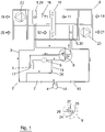
- Figure 1 shows a principal layout of a preferred embodiment of a heat pump 2 in which the method according to the present invention is implemente, arranged as a part of an air handling unit 9. It should be understood that the functions as well can be arranged as an entire unit module or a number of smaller modules joining to an air handling unit 9. Besides, should also be mentioned that the air handling unit 9 also includes other components which are not shown in the figures, such as filters, any other heaters and coolers, sensors etc. According to the embodiment shown in the figure a first air stream 11 is arranged in the upper half of the complete air handling unit 9, and in the flow direction of the first air stream 11, in the figure from right to left, the first air stream 11 comprises exhaust air 18 for example from a room, apartment or the like.
- the exhaust air 18 passes a filter (not shown) before it reaches a heat recovery device 10.
- a heat recovery device 10 is a controllable rotating heat recovery device 10.
- the first air stream 11 passes an evaporator 1, which is constituted by a first DX-coil 29, and then the air passes an exhaust fan 22, which drives the first air stream 11.
- the air leaves the air handling unit 9 and is thereby named extract air 19, which is released in the open air outside the building.
- extract air 19 which is released in the open air outside the building.
- the lower part of the air handling unit 9 there is a second air stream 12, and in succession from left to right in the figure, outdoor air 20 which is sucked into the air handling unit 9.
- the outdoor air 20 passes normally a filter (not shown) before it reaches the heat recovery device 10.
- the second air stream 12 reaches a condenser 6, which consist of a second DX-coil 30, and thereafter the air passes a supply fan 23, which drives the second air stream 12 through the air handling unit 9 and further into the premises.
- a supply fan 23 which drives the second air stream 12 through the air handling unit 9 and further into the premises.
- the heat pump 2 in turn comprises a refrigerant system 3 with a refrigerant 4, and at normal operation of the heating case, the following components are included, all of course connected with conduits, in order as follows.
- a compressor 5 followed by a four-way valve 8 with a first inlet 24, arranged for the inflow of refrigerant 4 from the compressor 5, further a first outlet 25 for the outflow of refrigerant 4 to the condenser 6, and a second outlet 26, for reflow of refrigerant 4 I direction to the compressor 5.
- a flash tank 17 between the second outlet 26 and the compressor 5, which flash tank 17 is arranged to separate eventual fluid refrigerant 4, to only let gaseous refrigerant 4 reach the compressor 5.
- the compressor 5 is very sensitive to fluid and to reach best performance in the system, one tries to inject a maximal amount of refrigerant 4 into the evaporator 1 without any refrigerant 4 exits the evaporator 1 as a fluid.
- instability can occur in the system and thereby lead to that liquid may come out of the evaporator 1. This may also occur if the refrigerant circuit is turned without stopping the compressor 5.
- the flash tank 17 any liquid coming out of the evaporator 1 is intercepted before it reaches the compressor 5.
- a second expansion valve 15 followed by a reservoir 14, arranged as a buffer for refrigerant 4 in the refrigerant system 3. While the cooling circuit works under different operation circumstances, different amounts of refrigerant 4 is needed in the system and the different needs of refrigerant 4 is buffered, according to the preferred embodiment in the reservoir 14 instead of the condenser 6, which otherwise is normal.
- a first expansion valve 7 followed by the evaporator 1/ the first DX-coil 29 and after this, the heat pump cycle is closed by that the evaporator 1 outlet connects to a second inlet 27 of the four-way valve 8.
- a so called bypass 28 for the refrigerant 4 which is arranged to send heated high pressure steam directly to the compressor 5, through a hot gas valve 13, to the evaporator 1, without passing the first expansion valve 7 or the second expansion valve 15.
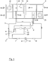
- the heat recovery device 10 During times when heating is required primarily the heat recovery device 10 is fully used to recover heat energy from the exhaust air 18 to heat the supply air 21. According to the example in figure 2 the controllable rotating heat recovery device 10 runs with maximum speed for maximum heat recovery. Thus the temperature T1 after the heat recovery device 10 becomes low and often the exhaust air 18 also contains some moisture. Temperature T1 is measured by a temperature sensor 16, which is positioned after the heat recovery device 10, in the flow direction of the first air stream 11. When the capacity of the heat recovery device 10 is not enough, additional heat must be added to the supply air 21, and according to the invention with help of the heat pump 2.
- the hot gas valve 13 is completely closed, while the second expansion valve 15 is completely opened and the first expansion valve 7 controls the flow of refrigerant over the evaporator 1 and regulates towards the so called superheat, described above.
- the superheat preferably is around 4-8 K for optimal operation.
- Figure 2 shows a preferred embodiment of the invention where the hot gas valve 13 is used for defrosting the evaporator 1, according to description below.
- the hot gas valve 13 opens during operation, namely at the same time as heating of the supply air 21 is performed by the condenser 6, and warm hot-gas is sent through the bypass 28 directly to the evaporator 1, to thaw the same from inside. While no energy is supplied to the evaporator 1, the energy is subsequently consumed in the system and eventually the energy in the system consist only of compressor energy, if no new energy is supplied. But by instead open the hot gas valve 13 limited while increasing compressor 5 speed, the defrosting and the energy consumption is controlled and the temperature in the evaporator 1 is increases at the same time as heating energy is delivered to the condenser 6.
- the reservoir 14 together with the first and second expansion valve 7,15 the super-heating and the amount of refrigerant 4 in the system is constantly balanced, for optimal operation.
- the two expansion valves 7,15 and the hot gas valve 13 are electronically controlled.
- the first expansion valve 7 together with the electronic hot gas valve 13, is balancing the relationship between hot gas bypass and flow of refrigerant over the evaporator 1, while the second expansion valve 15 is balancing the flow of refrigerant over the condenser 6.
- Figure 3 shows a principal layout of the heat pump 2 according to the invention, during reversible operation for defrosting of the evaporator 1. Principally, the figure also shows cooling mode when cooling demand is at hand. Just like for conventional heat pumps it is fully possible to run the heat pump 2 reversed for defrosting of the evaporator 1. By indication of icing in the evaporator 1 the four-way valve 8 switches for reversible operation and sends the warm hot-gas/refrigerant 4 directly to the evaporator 1, i.e. the first DX-coil 29 positioned in the first air stream 11.
- the first DX-coil 29 is heated from the inside and because of that the cooling power is reduced in the evaporator 1/the first DX-coil 29, the passing exhaust air 18/extract air 19 gets warmer, and double-sided defrosting of the evaporator 1/the first DX-coil 29 occurs.
- This can preferably be combined with simultaneously down-regulating the speed of the rotating heat recovery device 10. This provides a more rapid progression of the defrosting sequence.
- the first DX-coil 29, i.e. the evaporator 1 of the heating mode, positioned in the first air stream 11, will be heated.
- the second DX-coil 30 is however cooled down during the reversible operation whereby the supply air 21 will be cooled.
- the heat recovery device 10 During times when cooling is required primarily the heat recovery device 10 is fully used to recover cooling from the exhaust air 18, if the exhaust air 18 is colder than the outdoor air 20, and cool down the supply air 21.
- the controllable rotating heat recovery device 10 runs with maximum speed for maximal cooling recovery.
- the four-way valve 8 has switched the flow direction of the refrigerant 4 to reversible operation, in this case for cooling operation.
- the compressor 5 regulates towards the preset value of the supply air 21 and the cooling power of the refrigerant circuit is depending on the speed of the compressor 5. From the second DX-coil cooling is now released to the supply air 21 while the condenser heat and the compressor heat are released in the first DX-coil 29 and follows the extract air 19 out in the free.
- the first DX-coil 29 constitutes condenser 6, and the second DX-coil 30 thus evaporator 1.
- the hot gas valve 13 is completely shut, while the first expansion valve 7 is completely open and the second expansion valve 15 controls the flow of refrigerant 4 over the second DX-coil 30 and regulates towards the preset value for superheat.
- the superheat is preferably around 4-8 K.
Applications Claiming Priority (2)
| Application Number | Priority Date | Filing Date | Title |
|---|---|---|---|
| SE1200784A SE537022C2 (sv) | 2012-12-21 | 2012-12-21 | Förfarande och anordning för avfrostning av en förångare vidett luftbehandlingsaggregat |
| PCT/SE2013/051440 WO2014098724A1 (en) | 2012-12-21 | 2013-12-03 | Method and apparatus for defrosting of an evaporator in connection with an air handling unit |
Publications (3)
| Publication Number | Publication Date |
|---|---|
| EP2936008A1 EP2936008A1 (en) | 2015-10-28 |
| EP2936008A4 EP2936008A4 (en) | 2016-09-07 |
| EP2936008B1 true EP2936008B1 (en) | 2022-08-10 |
Family
ID=50978859
Family Applications (1)
| Application Number | Title | Priority Date | Filing Date |
|---|---|---|---|
| EP13864219.4A Active EP2936008B1 (en) | 2012-12-21 | 2013-12-03 | Method for defrosting of an evaporator in connection with an air handling unit |
Country Status (9)
| Country | Link |
|---|---|
| US (1) | US9423164B2 (sv) |
| EP (1) | EP2936008B1 (sv) |
| JP (1) | JP2015535071A (sv) |
| KR (1) | KR101576431B1 (sv) |
| CN (1) | CN104813122B (sv) |
| HK (1) | HK1211079A1 (sv) |
| RU (1) | RU2638704C2 (sv) |
| SE (1) | SE537022C2 (sv) |
| WO (1) | WO2014098724A1 (sv) |
Families Citing this family (22)
| Publication number | Priority date | Publication date | Assignee | Title |
|---|---|---|---|---|
| SE538309C2 (sv) | 2013-11-26 | 2016-05-10 | Fläkt Woods AB | Anordning och förfarande för värmning av luft vid en luftbehandlingsanordning |
| CN104329790A (zh) * | 2014-11-14 | 2015-02-04 | 四川创境科技有限公司 | 用于通信基站机房的节能型换热设备及其构成的空调系统 |
| CN107076477B (zh) * | 2014-11-24 | 2021-04-27 | 开利公司 | 用于自由和积极除霜的系统和方法 |
| JP6296964B2 (ja) * | 2014-11-27 | 2018-03-20 | エスペック株式会社 | 環境試験装置及び冷却装置 |
| SE539671C2 (sv) * | 2014-12-23 | 2017-10-31 | Fläkt Woods AB | Anordning och förfarande för värmning av luft vid en luftbehandlingsanordning. |
| CN105157172B (zh) * | 2015-08-31 | 2018-03-30 | Tcl空调器(中山)有限公司 | 空调器的控制方法及装置 |
| ITUB20160682A1 (it) * | 2016-03-01 | 2017-09-01 | Evolving Living Innovation Center Elic S R L | Apparecchiatura a pompa di calore per il ricambio dell’aria in locali domestici e suo metodo di funzionamento |
| JP6540551B2 (ja) * | 2016-03-02 | 2019-07-10 | 株式会社デンソー | 空調装置 |
| SE542633C2 (sv) * | 2016-05-17 | 2020-06-23 | Lars Friberg Evolution Ab | Anordning för snabbavfrostning utan kompressorstopp av förångaren i en luft-vatten-värmepump och för att köra värmepumpen vid extremt låga förångartemepraturer och vid extremt lågalaster |
| SE540118C2 (sv) * | 2016-06-16 | 2018-04-03 | Flaekt Woods Ab | Sätt och anordning för att minska eller eliminera sänkningenav tilluftstemperaturen under avfrostning av en förångare v id ett luftbehandlingsaggregat |
| CN106545947A (zh) * | 2017-01-24 | 2017-03-29 | 北京代克环能技术有限公司 | 一种高寒地区防冰堵热回收新风换气机及其换气方法 |
| SE540832C2 (sv) * | 2017-04-28 | 2018-11-27 | Flaektgroup Sweden Ab | Luftbehandlingsanordning med delvis indirekt anordnad värmepump och metod att vid sådan reducera sänkningen av tilluftstemperaturen under avfrostningsdrift |
| JP6804648B2 (ja) * | 2017-07-07 | 2020-12-23 | 三菱電機株式会社 | 冷凍サイクル装置 |
| EP3745053A4 (en) * | 2018-01-26 | 2021-01-13 | Mitsubishi Electric Corporation | REFRIGERATION CIRCUIT DEVICE |
| CN108151363A (zh) * | 2018-02-05 | 2018-06-12 | 徐生恒 | 全天候空气能热泵空调系统 |
| US11619431B2 (en) | 2018-04-13 | 2023-04-04 | Carrier Corporation | Method of defrosting a multiple heat absorption heat exchanger refrigeration system |
| CN109708273B (zh) * | 2018-12-29 | 2021-10-08 | 广东美的暖通设备有限公司 | 低温制冷风阀的控制方法及其装置 |
| CN111121337B (zh) * | 2019-12-31 | 2022-03-22 | 宁波奥克斯电气股份有限公司 | 空调双冷凝器除霜方法和空调 |
| CN111140976A (zh) * | 2020-01-17 | 2020-05-12 | 珠海格力电器股份有限公司 | 新风空调系统及其控制方法 |
| EP3862660A1 (en) | 2020-02-06 | 2021-08-11 | Carrier Corporation | Heat pump system |
| EP4308858A1 (en) * | 2021-03-19 | 2024-01-24 | Zehnder Group International AG | Heat recovery ventilation system with defrosting bypass |
| WO2023287035A1 (ko) * | 2021-07-12 | 2023-01-19 | 엘지전자 주식회사 | 냉장고 |
Citations (1)
| Publication number | Priority date | Publication date | Assignee | Title |
|---|---|---|---|---|
| JPH0387547A (ja) * | 1989-08-30 | 1991-04-12 | Kubota Toreen Kk | パッケージエアコンの除霜方法 |
Family Cites Families (30)
| Publication number | Priority date | Publication date | Assignee | Title |
|---|---|---|---|---|
| DE2442420C3 (de) * | 1974-09-05 | 1979-10-31 | Basf Ag, 6700 Ludwigshafen | Desublimator für die Gewinnung von Sublimationsprodukten, insbesondere von Phthalsäureanhydrid, aus Reaktionsgasen |
| GB1556064A (en) | 1977-12-19 | 1979-11-21 | Lennox Ind Ltd | Heating or cooling devices for buildings |
| JPH0799297B2 (ja) * | 1986-06-25 | 1995-10-25 | 株式会社日立製作所 | 空気調和機 |
| JPS63153374A (ja) * | 1986-12-17 | 1988-06-25 | 株式会社日立製作所 | 空気調和機 |
| JPH076712B2 (ja) | 1987-07-10 | 1995-01-30 | 株式会社東芝 | 冷凍サイクル装置 |
| JPH0518645A (ja) * | 1991-07-10 | 1993-01-26 | Nippondenso Co Ltd | ヒートポンプ式空気調和装置 |
| US5203179A (en) * | 1992-03-04 | 1993-04-20 | Ecoair Corporation | Control system for an air conditioning/refrigeration system |
| JPH06257828A (ja) * | 1993-03-02 | 1994-09-16 | Matsushita Electric Ind Co Ltd | 多室形空気調和システム |
| US5309725A (en) * | 1993-07-06 | 1994-05-10 | Cayce James L | System and method for high-efficiency air cooling and dehumidification |
| JP3242527B2 (ja) * | 1994-05-13 | 2001-12-25 | 株式会社東洋製作所 | 空気調和機 |
| US6442951B1 (en) * | 1998-06-30 | 2002-09-03 | Ebara Corporation | Heat exchanger, heat pump, dehumidifier, and dehumidifying method |
| CN1308717A (zh) * | 1998-06-30 | 2001-08-15 | 株式会社荏原制作所 | 热交换器、热泵、除湿装置和除湿方法 |
| US6141979A (en) | 1999-11-19 | 2000-11-07 | American Standard Inc. | Dual heat exchanger wheels with variable speed |
| WO2001084066A1 (en) * | 2000-05-01 | 2001-11-08 | University Of Maryland | Device for collecting water from air |
| US7043934B2 (en) | 2000-05-01 | 2006-05-16 | University Of Maryland, College Park | Device for collecting water from air |
| JP4518998B2 (ja) * | 2005-04-28 | 2010-08-04 | 株式会社東洋製作所 | ヒートポンプ式空気調和装置 |
| RU2008102367A (ru) * | 2005-06-23 | 2009-07-27 | Кэрриер Корпорейшн (Us) | Способ размораживания испарителя в холодильном контуре |
| US7856836B2 (en) * | 2005-07-26 | 2010-12-28 | Mitsubishi Electric Corporation | Refrigerating air conditioning system |
| KR100788302B1 (ko) * | 2006-04-13 | 2007-12-27 | 주식회사 코벡엔지니어링 | 고속제상 히트펌프 |
| JP4816267B2 (ja) * | 2006-06-09 | 2011-11-16 | 日本エクスラン工業株式会社 | 湿度調節装置 |
| US7886986B2 (en) * | 2006-11-08 | 2011-02-15 | Semco Inc. | Building, ventilation system, and recovery device control |
| KR100712196B1 (ko) | 2007-01-24 | 2007-04-27 | 충주대학교 산학협력단 | 히트펌프 시스템 및 실외기 제상 방법 |
| JP5076745B2 (ja) * | 2007-08-31 | 2012-11-21 | パナソニック株式会社 | 換気空調装置 |
| JP5100416B2 (ja) * | 2008-01-25 | 2012-12-19 | 三菱電機株式会社 | 再熱除湿装置および空気調和装置 |
| RU2389945C2 (ru) * | 2008-07-31 | 2010-05-20 | Общество с ограниченной ответственностью "Завод стеновых блоков" | Топочное устройство для сжигания жидкого топлива |
| JP5570531B2 (ja) * | 2010-01-26 | 2014-08-13 | 三菱電機株式会社 | ヒートポンプ装置 |
| JP5418280B2 (ja) * | 2010-02-17 | 2014-02-19 | 株式会社デンソー | 蒸発器 |
| US8943848B2 (en) * | 2010-06-16 | 2015-02-03 | Reznor Llc | Integrated ventilation unit |
| US8915092B2 (en) * | 2011-01-19 | 2014-12-23 | Venmar Ces, Inc. | Heat pump system having a pre-processing module |
| SE537199C2 (sv) | 2011-11-23 | 2015-03-03 | Swegon Ab | System för styrning av inomhusklimatet i en byggnad |
-
2012
- 2012-12-21 SE SE1200784A patent/SE537022C2/sv unknown
-
2013
- 2013-12-03 KR KR1020157011524A patent/KR101576431B1/ko active IP Right Grant
- 2013-12-03 EP EP13864219.4A patent/EP2936008B1/en active Active
- 2013-12-03 CN CN201380061069.9A patent/CN104813122B/zh active Active
- 2013-12-03 JP JP2015541742A patent/JP2015535071A/ja active Pending
- 2013-12-03 RU RU2015114916A patent/RU2638704C2/ru active
- 2013-12-03 US US14/441,347 patent/US9423164B2/en active Active
- 2013-12-03 WO PCT/SE2013/051440 patent/WO2014098724A1/en active Search and Examination
-
2015
- 2015-11-26 HK HK15111641.3A patent/HK1211079A1/xx unknown
Patent Citations (1)
| Publication number | Priority date | Publication date | Assignee | Title |
|---|---|---|---|---|
| JPH0387547A (ja) * | 1989-08-30 | 1991-04-12 | Kubota Toreen Kk | パッケージエアコンの除霜方法 |
Also Published As
| Publication number | Publication date |
|---|---|
| CN104813122A (zh) | 2015-07-29 |
| RU2638704C2 (ru) | 2017-12-15 |
| HK1211079A1 (en) | 2016-05-13 |
| US9423164B2 (en) | 2016-08-23 |
| SE537022C2 (sv) | 2014-12-09 |
| EP2936008A1 (en) | 2015-10-28 |
| EP2936008A4 (en) | 2016-09-07 |
| US20150292786A1 (en) | 2015-10-15 |
| SE1200784A1 (sv) | 2014-06-22 |
| KR20150062172A (ko) | 2015-06-05 |
| CN104813122B (zh) | 2017-08-29 |
| JP2015535071A (ja) | 2015-12-07 |
| KR101576431B1 (ko) | 2015-12-21 |
| RU2015114916A (ru) | 2016-11-10 |
| WO2014098724A1 (en) | 2014-06-26 |
Similar Documents
| Publication | Publication Date | Title |
|---|---|---|
| EP2936008B1 (en) | Method for defrosting of an evaporator in connection with an air handling unit | |
| US10823482B2 (en) | Systems and methods for free and positive defrost | |
| CN111351248B (zh) | 一种空调系统及控制方法 | |
| JP5595140B2 (ja) | ヒートポンプ式給湯・空調装置 | |
| CN108139086B (zh) | 空调及控制空调的方法 | |
| JP5095295B2 (ja) | 給湯装置 | |
| US9797611B2 (en) | Combination air and ground source heating and/or cooling system | |
| CN102741624A (zh) | 涡轮制冷机和制冷系统及其控制方法 | |
| CN104220818A (zh) | 空调机 | |
| JP5404761B2 (ja) | 冷凍装置 | |
| CN206973766U (zh) | 一种热气旁通无霜低温除湿机 | |
| JP5517891B2 (ja) | 空気調和装置 | |
| JP5693990B2 (ja) | 空気熱源ヒートポンプエアコン | |
| GB2545112A (en) | Refrigeration cycle device and air-conditioning device | |
| CN201047687Y (zh) | 热气旁通回气补热除霜恒温热水系统 | |
| JP2012251667A (ja) | 空気冷媒式冷凍装置のデフロスト方法及び装置 | |
| JP4409316B2 (ja) | 冷却装置 | |
| CN108679716A (zh) | 换热系统 | |
| JP2016023921A (ja) | ヒートポンプ給湯システム | |
| WO2021014644A1 (ja) | 空気調和装置 | |
| KR100937202B1 (ko) | 건조기 및 냉동창고를 겸한 냉동기 유니트 | |
| CN109210814A (zh) | 一种多功能制冷系统 | |
| JP5398296B2 (ja) | エンジン駆動式空気調和機 | |
| EP3789695A1 (en) | A hvac system | |
| KR20090085373A (ko) | 히트 펌프 급탕기 및 그 제어 방법 |
Legal Events
| Date | Code | Title | Description |
|---|---|---|---|
| PUAI | Public reference made under article 153(3) epc to a published international application that has entered the european phase |
Free format text: ORIGINAL CODE: 0009012 |
|
| 17P | Request for examination filed |
Effective date: 20150416 |
|
| AK | Designated contracting states |
Kind code of ref document: A1 Designated state(s): AL AT BE BG CH CY CZ DE DK EE ES FI FR GB GR HR HU IE IS IT LI LT LU LV MC MK MT NL NO PL PT RO RS SE SI SK SM TR |
|
| AX | Request for extension of the european patent |
Extension state: BA ME |
|
| DAX | Request for extension of the european patent (deleted) | ||
| A4 | Supplementary search report drawn up and despatched |
Effective date: 20160805 |
|
| RIC1 | Information provided on ipc code assigned before grant |
Ipc: F25D 21/06 20060101ALI20160801BHEP Ipc: F24F 12/00 20060101ALI20160801BHEP Ipc: F25B 47/02 20060101AFI20160801BHEP Ipc: F25B 13/00 20060101ALI20160801BHEP |
|
| RAP1 | Party data changed (applicant data changed or rights of an application transferred) |
Owner name: FLAEKTGROUP SWEDEN AB |
|
| STAA | Information on the status of an ep patent application or granted ep patent |
Free format text: STATUS: EXAMINATION IS IN PROGRESS |
|
| 17Q | First examination report despatched |
Effective date: 20200706 |
|
| STAA | Information on the status of an ep patent application or granted ep patent |
Free format text: STATUS: EXAMINATION IS IN PROGRESS |
|
| GRAP | Despatch of communication of intention to grant a patent |
Free format text: ORIGINAL CODE: EPIDOSNIGR1 |
|
| STAA | Information on the status of an ep patent application or granted ep patent |
Free format text: STATUS: GRANT OF PATENT IS INTENDED |
|
| INTG | Intention to grant announced |
Effective date: 20220302 |
|
| GRAS | Grant fee paid |
Free format text: ORIGINAL CODE: EPIDOSNIGR3 |
|
| GRAA | (expected) grant |
Free format text: ORIGINAL CODE: 0009210 |
|
| STAA | Information on the status of an ep patent application or granted ep patent |
Free format text: STATUS: THE PATENT HAS BEEN GRANTED |
|
| AK | Designated contracting states |
Kind code of ref document: B1 Designated state(s): AL AT BE BG CH CY CZ DE DK EE ES FI FR GB GR HR HU IE IS IT LI LT LU LV MC MK MT NL NO PL PT RO RS SE SI SK SM TR |
|
| REG | Reference to a national code |
Ref country code: GB Ref legal event code: FG4D |
|
| REG | Reference to a national code |
Ref country code: AT Ref legal event code: REF Ref document number: 1510824 Country of ref document: AT Kind code of ref document: T Effective date: 20220815 Ref country code: CH Ref legal event code: EP |
|
| REG | Reference to a national code |
Ref country code: DE Ref legal event code: R096 Ref document number: 602013082303 Country of ref document: DE |
|
| REG | Reference to a national code |
Ref country code: IE Ref legal event code: FG4D |
|
| REG | Reference to a national code |
Ref country code: FI Ref legal event code: FGE |
|
| REG | Reference to a national code |
Ref country code: NO Ref legal event code: T2 Effective date: 20220810 |
|
| REG | Reference to a national code |
Ref country code: SE Ref legal event code: TRGR |
|
| REG | Reference to a national code |
Ref country code: NL Ref legal event code: MP Effective date: 20220810 |
|
| REG | Reference to a national code |
Ref country code: LT Ref legal event code: MG9D |
|
| PG25 | Lapsed in a contracting state [announced via postgrant information from national office to epo] |
Ref country code: RS Free format text: LAPSE BECAUSE OF FAILURE TO SUBMIT A TRANSLATION OF THE DESCRIPTION OR TO PAY THE FEE WITHIN THE PRESCRIBED TIME-LIMIT Effective date: 20220810 Ref country code: PT Free format text: LAPSE BECAUSE OF FAILURE TO SUBMIT A TRANSLATION OF THE DESCRIPTION OR TO PAY THE FEE WITHIN THE PRESCRIBED TIME-LIMIT Effective date: 20221212 Ref country code: NL Free format text: LAPSE BECAUSE OF FAILURE TO SUBMIT A TRANSLATION OF THE DESCRIPTION OR TO PAY THE FEE WITHIN THE PRESCRIBED TIME-LIMIT Effective date: 20220810 Ref country code: LV Free format text: LAPSE BECAUSE OF FAILURE TO SUBMIT A TRANSLATION OF THE DESCRIPTION OR TO PAY THE FEE WITHIN THE PRESCRIBED TIME-LIMIT Effective date: 20220810 Ref country code: LT Free format text: LAPSE BECAUSE OF FAILURE TO SUBMIT A TRANSLATION OF THE DESCRIPTION OR TO PAY THE FEE WITHIN THE PRESCRIBED TIME-LIMIT Effective date: 20220810 Ref country code: ES Free format text: LAPSE BECAUSE OF FAILURE TO SUBMIT A TRANSLATION OF THE DESCRIPTION OR TO PAY THE FEE WITHIN THE PRESCRIBED TIME-LIMIT Effective date: 20220810 |
|
| PG25 | Lapsed in a contracting state [announced via postgrant information from national office to epo] |
Ref country code: PL Free format text: LAPSE BECAUSE OF FAILURE TO SUBMIT A TRANSLATION OF THE DESCRIPTION OR TO PAY THE FEE WITHIN THE PRESCRIBED TIME-LIMIT Effective date: 20220810 Ref country code: IS Free format text: LAPSE BECAUSE OF FAILURE TO SUBMIT A TRANSLATION OF THE DESCRIPTION OR TO PAY THE FEE WITHIN THE PRESCRIBED TIME-LIMIT Effective date: 20221210 Ref country code: HR Free format text: LAPSE BECAUSE OF FAILURE TO SUBMIT A TRANSLATION OF THE DESCRIPTION OR TO PAY THE FEE WITHIN THE PRESCRIBED TIME-LIMIT Effective date: 20220810 Ref country code: GR Free format text: LAPSE BECAUSE OF FAILURE TO SUBMIT A TRANSLATION OF THE DESCRIPTION OR TO PAY THE FEE WITHIN THE PRESCRIBED TIME-LIMIT Effective date: 20221111 |
|
| PG25 | Lapsed in a contracting state [announced via postgrant information from national office to epo] |
Ref country code: SM Free format text: LAPSE BECAUSE OF FAILURE TO SUBMIT A TRANSLATION OF THE DESCRIPTION OR TO PAY THE FEE WITHIN THE PRESCRIBED TIME-LIMIT Effective date: 20220810 Ref country code: RO Free format text: LAPSE BECAUSE OF FAILURE TO SUBMIT A TRANSLATION OF THE DESCRIPTION OR TO PAY THE FEE WITHIN THE PRESCRIBED TIME-LIMIT Effective date: 20220810 Ref country code: DK Free format text: LAPSE BECAUSE OF FAILURE TO SUBMIT A TRANSLATION OF THE DESCRIPTION OR TO PAY THE FEE WITHIN THE PRESCRIBED TIME-LIMIT Effective date: 20220810 Ref country code: CZ Free format text: LAPSE BECAUSE OF FAILURE TO SUBMIT A TRANSLATION OF THE DESCRIPTION OR TO PAY THE FEE WITHIN THE PRESCRIBED TIME-LIMIT Effective date: 20220810 |
|
| REG | Reference to a national code |
Ref country code: DE Ref legal event code: R097 Ref document number: 602013082303 Country of ref document: DE |
|
| PG25 | Lapsed in a contracting state [announced via postgrant information from national office to epo] |
Ref country code: SK Free format text: LAPSE BECAUSE OF FAILURE TO SUBMIT A TRANSLATION OF THE DESCRIPTION OR TO PAY THE FEE WITHIN THE PRESCRIBED TIME-LIMIT Effective date: 20220810 Ref country code: EE Free format text: LAPSE BECAUSE OF FAILURE TO SUBMIT A TRANSLATION OF THE DESCRIPTION OR TO PAY THE FEE WITHIN THE PRESCRIBED TIME-LIMIT Effective date: 20220810 |
|
| PLBE | No opposition filed within time limit |
Free format text: ORIGINAL CODE: 0009261 |
|
| STAA | Information on the status of an ep patent application or granted ep patent |
Free format text: STATUS: NO OPPOSITION FILED WITHIN TIME LIMIT |
|
| PG25 | Lapsed in a contracting state [announced via postgrant information from national office to epo] |
Ref country code: AL Free format text: LAPSE BECAUSE OF FAILURE TO SUBMIT A TRANSLATION OF THE DESCRIPTION OR TO PAY THE FEE WITHIN THE PRESCRIBED TIME-LIMIT Effective date: 20220810 |
|
| P01 | Opt-out of the competence of the unified patent court (upc) registered |
Effective date: 20230526 |
|
| 26N | No opposition filed |
Effective date: 20230511 |
|
| REG | Reference to a national code |
Ref country code: CH Ref legal event code: PL |
|
| REG | Reference to a national code |
Ref country code: BE Ref legal event code: MM Effective date: 20221231 |
|
| PG25 | Lapsed in a contracting state [announced via postgrant information from national office to epo] |
Ref country code: SI Free format text: LAPSE BECAUSE OF FAILURE TO SUBMIT A TRANSLATION OF THE DESCRIPTION OR TO PAY THE FEE WITHIN THE PRESCRIBED TIME-LIMIT Effective date: 20220810 Ref country code: LU Free format text: LAPSE BECAUSE OF NON-PAYMENT OF DUE FEES Effective date: 20221203 |
|
| PG25 | Lapsed in a contracting state [announced via postgrant information from national office to epo] |
Ref country code: LI Free format text: LAPSE BECAUSE OF NON-PAYMENT OF DUE FEES Effective date: 20221231 Ref country code: IE Free format text: LAPSE BECAUSE OF NON-PAYMENT OF DUE FEES Effective date: 20221203 Ref country code: CH Free format text: LAPSE BECAUSE OF NON-PAYMENT OF DUE FEES Effective date: 20221231 |
|
| PG25 | Lapsed in a contracting state [announced via postgrant information from national office to epo] |
Ref country code: BE Free format text: LAPSE BECAUSE OF NON-PAYMENT OF DUE FEES Effective date: 20221231 |
|
| PGFP | Annual fee paid to national office [announced via postgrant information from national office to epo] |
Ref country code: GB Payment date: 20231215 Year of fee payment: 11 |
|
| PGFP | Annual fee paid to national office [announced via postgrant information from national office to epo] |
Ref country code: SE Payment date: 20231218 Year of fee payment: 11 Ref country code: NO Payment date: 20231218 Year of fee payment: 11 Ref country code: FR Payment date: 20231215 Year of fee payment: 11 Ref country code: FI Payment date: 20231214 Year of fee payment: 11 Ref country code: DE Payment date: 20231218 Year of fee payment: 11 Ref country code: AT Payment date: 20231218 Year of fee payment: 11 |
|
| PG25 | Lapsed in a contracting state [announced via postgrant information from national office to epo] |
Ref country code: HU Free format text: LAPSE BECAUSE OF FAILURE TO SUBMIT A TRANSLATION OF THE DESCRIPTION OR TO PAY THE FEE WITHIN THE PRESCRIBED TIME-LIMIT; INVALID AB INITIO Effective date: 20131203 |
|
| PG25 | Lapsed in a contracting state [announced via postgrant information from national office to epo] |
Ref country code: CY Free format text: LAPSE BECAUSE OF FAILURE TO SUBMIT A TRANSLATION OF THE DESCRIPTION OR TO PAY THE FEE WITHIN THE PRESCRIBED TIME-LIMIT Effective date: 20220810 |