EP2934708B1 - Dispositif pour rectifier des irrégularités de surface d'une pelouse, et club de golf muni d'un tel dispositif - Google Patents
Dispositif pour rectifier des irrégularités de surface d'une pelouse, et club de golf muni d'un tel dispositif Download PDFInfo
- Publication number
- EP2934708B1 EP2934708B1 EP15700585.1A EP15700585A EP2934708B1 EP 2934708 B1 EP2934708 B1 EP 2934708B1 EP 15700585 A EP15700585 A EP 15700585A EP 2934708 B1 EP2934708 B1 EP 2934708B1
- Authority
- EP
- European Patent Office
- Prior art keywords
- connecting element
- segment
- grip
- golf club
- attaching
- Prior art date
- Legal status (The legal status is an assumption and is not a legal conclusion. Google has not performed a legal analysis and makes no representation as to the accuracy of the status listed.)
- Not-in-force
Links
Images


Classifications
-
- A—HUMAN NECESSITIES
- A63—SPORTS; GAMES; AMUSEMENTS
- A63B—APPARATUS FOR PHYSICAL TRAINING, GYMNASTICS, SWIMMING, CLIMBING, OR FENCING; BALL GAMES; TRAINING EQUIPMENT
- A63B57/00—Golfing accessories
-
- A—HUMAN NECESSITIES
- A01—AGRICULTURE; FORESTRY; ANIMAL HUSBANDRY; HUNTING; TRAPPING; FISHING
- A01B—SOIL WORKING IN AGRICULTURE OR FORESTRY; PARTS, DETAILS, OR ACCESSORIES OF AGRICULTURAL MACHINES OR IMPLEMENTS, IN GENERAL
- A01B1/00—Hand tools
- A01B1/24—Hand tools for treating meadows or lawns
-
- A—HUMAN NECESSITIES
- A63—SPORTS; GAMES; AMUSEMENTS
- A63B—APPARATUS FOR PHYSICAL TRAINING, GYMNASTICS, SWIMMING, CLIMBING, OR FENCING; BALL GAMES; TRAINING EQUIPMENT
- A63B53/00—Golf clubs
- A63B53/14—Handles
-
- A—HUMAN NECESSITIES
- A63—SPORTS; GAMES; AMUSEMENTS
- A63B—APPARATUS FOR PHYSICAL TRAINING, GYMNASTICS, SWIMMING, CLIMBING, OR FENCING; BALL GAMES; TRAINING EQUIPMENT
- A63B60/00—Details or accessories of golf clubs, bats, rackets or the like
- A63B60/06—Handles
- A63B60/16—Caps; Ferrules
-
- A—HUMAN NECESSITIES
- A63—SPORTS; GAMES; AMUSEMENTS
- A63B—APPARATUS FOR PHYSICAL TRAINING, GYMNASTICS, SWIMMING, CLIMBING, OR FENCING; BALL GAMES; TRAINING EQUIPMENT
- A63B2225/00—Miscellaneous features of sport apparatus, devices or equipment
- A63B2225/68—Miscellaneous features of sport apparatus, devices or equipment with article holders
-
- A—HUMAN NECESSITIES
- A63—SPORTS; GAMES; AMUSEMENTS
- A63B—APPARATUS FOR PHYSICAL TRAINING, GYMNASTICS, SWIMMING, CLIMBING, OR FENCING; BALL GAMES; TRAINING EQUIPMENT
- A63B57/00—Golfing accessories
- A63B57/20—Holders, e.g. of tees or of balls
- A63B57/207—Golf ball position marker holders
-
- A—HUMAN NECESSITIES
- A63—SPORTS; GAMES; AMUSEMENTS
- A63B—APPARATUS FOR PHYSICAL TRAINING, GYMNASTICS, SWIMMING, CLIMBING, OR FENCING; BALL GAMES; TRAINING EQUIPMENT
- A63B57/00—Golfing accessories
- A63B57/30—Markers
- A63B57/353—Golf ball position markers
-
- A—HUMAN NECESSITIES
- A63—SPORTS; GAMES; AMUSEMENTS
- A63B—APPARATUS FOR PHYSICAL TRAINING, GYMNASTICS, SWIMMING, CLIMBING, OR FENCING; BALL GAMES; TRAINING EQUIPMENT
- A63B57/00—Golfing accessories
- A63B57/50—Golfing accessories specially adapted for course maintenance
Definitions
- the invention relates to a device for repairing unevenness in a green area arranged on a ground.
- the device is adapted to be attached to a handle of a golf club.
- the device is, in particular, a so-called pitch fork or divot tool, a tool used in golf, around depressions or dents which strike balls from a comparatively great height on the so-called "green" of a golf course, a green area arranged on a ground have arisen, the so-called pitch marks, to mend.
- These pitch marks are due to the fact that when golfing from a short distance in the direction of hole beaten balls are often played in a high arc, the so-called pitch, to avoid that the ball rolls over the short-cut lawn of the "green". If the pitch marks are not repaired, the area around the hole will be uneven and the puttering of a ball, the so-called putting, will be difficult on later rounds.
- Pitchforks are available in various designs. Usually they are carried as a separate utensil during the game by the golfer in his pocket.
- a pitch fork attached to the handle end of a golf club slidably disposed along a longitudinal axis for moving from a use position in which the tines of the pitch fork protrude from the handle end to a stowage position in which the tines of the pitch fork come to rest inside the handle to be brought describes US 5,511,785 .
- Such pitch forks which are displaceable between a position of use and a stowed position also go out US 4,955,609 .
- US 2003/0109336 A1 and US Pat. No. 7,351,158 B1 out reveal US 4,925,190 and US 5,277,425 Pitch forks attached to the end of the handle of a golf club, protected by a separate cap when not in use.
- the cover cap is force-fitted on the pitch fork.
- a fixed at the end of the handle of a golf club repair tool, which is covered by a frictionally plugged cap when not in use, is further in US 2007/0060412 A1 disclosed.
- the repair tool is attached by means of a screw to the handle end.
- WO 02/47770 A1 discloses a pitch fork attached to the end of the handle of a golf club, which when not in use is covered with a cap by means of a plug-and-turn motion along a T-shaped groove.
- a screw-threaded pitch fork that screws into the grip end of a golf club is disclosed US 2007/0298900 A1 ,
- the pitch fork has a central portion provided with an external thread.
- the external thread makes it possible to unscrew a cap, which covers the pitch fork when not in use.
- GB 16896A discloses a two-piece golf club, which can be disassembled by means of a predetermined by an L-shaped groove rotational movement. Further disclosed GB 2 220 576 A a golf club, which is removable by means of a rotation caused by an L-shaped groove.
- the invention has for its object to provide a device for repairing bumps in a located on a ground green area, especially the green of a golf course, which can be attached to the handle of a golf club and by which the handling of the golf club is not affected.
- the device according to the invention for repairing unevenness in a green area arranged on a ground comprises a fastening element, by means of which the device can be fastened to the handle of a golf club, and an insertion element which is suitable for being introduced into the ground for repairing unevenness.
- the insertion element is in particular a pitch fork.
- the device further comprises a cover element or cap for covering the insertion element. By the cover member of the user of the golf club is protected from injury that may be caused by the insertion.
- the device comprises a connecting element which can be detachably connected to the cover element by means of a bayonet closure.
- the connection of the cover element and connecting element is accordingly via a plug-in rotary movement.
- the connecting element has at least one recess, which has a beginning portion and an end portion.
- the cover member has at least one protrusion which engages the recess and can be moved to connect the cover member and connecting member from the starting portion to the end portion.
- the projection is moved from the end portion back into the initial section.
- at least one depression on the cover element and at least one projection engaging in the depression can be formed on the connection element.
- the cover element can be separated from the connecting element and thus the cover element can be removed from the insertion element.
- the projection is held positively and non-positively in the recess.
- the cover member is thus reliably connected to the connecting member, and so sure that the handling of the golf club is not affected. Neither does the cover element accidentally disengage when the golf club is in use, nor is the so-called grip pressure, which is important for holding the golf club, affected by the cover element.
- the connecting element has an upper side, a lower side and a lateral surface, which is preferably cylindrical, in particular circular-cylindrical.
- the connecting element is preferably composed of an upper part and a lower part which has a smaller diameter than the upper part together.
- the recess is configured as a groove which extends along a trajectory along the lateral surface.
- the trajectory or a further trajectory may extend along a preferably cylindrical, in particular circular cylindrical, inner surface of the cover element, in particular when the projection is formed alternatively or additionally on the connecting element.
- the trajectory in the transition region from the initial section to the end section has an at least local low point.
- the sign of the slope of the trajectory in the initial section is inverse to the sign of the gradient in the end section.
- the projection is movable against the action of a restoring force acting in an axial direction from the initial portion to the end portion. If the projection in the initial section is moved along a falling trajectory, then the sign of the slope is Trajectory, for example, negative. After reaching the low point, the sign changes the slope of the trajectory and is positive. The projection is thus moved in the end portion along a rising trajectory.
- the end portion is limited by an end stop for the projection.
- the slope of the trajectory in the end portion decreases toward the end stop.
- there is a local high point just before the end stop that is, the trajectory falls slightly towards the end stop again.
- the slope of the trajectory specifically the force with which the cover element and the connecting element must be braced against each other when reaching the end stop, on the one hand a solid Seat and on the other hand to ensure a comfortable release of the cover element.
- the end stop also provides feedback to the user when the cover member is securely connected to the connector.
- the cover element has an upper side and a lower side and has at least one cavity opening out on the underside.
- the cavity is adapted to receive the insertion element and the connecting element.
- Other cavities may serve, for example, to give the cover member a certain deformability or hardness. Tougher grips provide good control and often encourage the player to hold the bat with less pressure. Softer handles, on the other hand, are generally easier to handle.
- the cover element is made of an elastically deformable material at least regionally, in particular in the region of the projection or the depression.
- a suitable material is for example rubber. Rubber is easy to shape and produce as a material and provides a firm, sticky feel.
- Other suitable material may be, for example, silicone, elastomers or other elastically deformable plastics or mixtures of the aforementioned materials.
- the cover element on the underside on a contact surface which is adapted to abut against an end face of the handle or a part of the handle of a golf club. If, for example, an existing golf club is retrofitted with the device according to the invention, it is possible to cut off a part of the handle and replace it with a cover element which corresponds in feel and grip to the severed part. The cut surface forms the end face in this case.
- the contact surface at least partially points with a friction-reducing surface. These locations can be formed for example by the cavities and serve to influence the sliding friction between the end face and contact surface.
- the cover element is elastically deformable, in particular in the region of the projection or of the recess, then it is possible to specify the distance between the contact surface of the cover element and the end face of the handle in such a way that the cover element must be slightly compressed when it is slipped onto the connecting element to move the projection into the end section. Due to the elastic deformation associated with the compression creates a restoring force acting in the axial direction, which is greatest in the low point and reliably clamped in the end portion of the cover member and the connecting element against each other.
- the cover member on the top of a holder which is adapted to hold a particular chip-shaped ball marker.
- the ball marker With the ball marker the position of a golf ball is marked on the green in order to be able to record it afterwards.
- a ballmarker coins or even designated snaps are often used on golf gloves use.
- Increasingly popular and often used as a giveaway are chip-shaped ball markers that can be personalized or printed.
- the insertion element preferably has a holding portion, which is preferably configured flat, and protruding from the holding portion prongs, which are preferably curved, on.
- the insertion element is thus a repair tool, a so-called pitch fork, the tines are pricked around the pitch mark in the lawn and moved in a suitable manner to reverse the deformation of the turf.
- the curvature of the tines bears to gently prick the tines into the grass, thus avoiding prolonged damage to the turf.
- the connecting element has on the upper side a first opening in which the holding section is arranged.
- the connecting element on the lateral surface on a second opening, in which a retaining portion fixing locking screw is received.
- the holding section is inserted into the first opening and then tightened, for example, designed as a set screw locking screw in the second, threaded opening.
- the fastening element and the connecting element are connected to one another by a screw connection.
- the connecting element for receiving a preferably extending in the axial direction screw is provided with a extending from the top to the bottom through hole.
- the fastener has a top and a bottom and is provided for supporting a cooperating with the screw nut with a particular formed on the bottom contact surface.
- the connecting element on the underside has a clamping surface which extends at a first angle obliquely to the axial direction
- the fastening element at the top has a clamping surface which has a center and under a second Angle extends obliquely to the axial direction.
- the first angle and the second angle preferably form secondary angles, thus complement each other to 180 °.
- the clamping surfaces are parallel in this case.
- the first angle between 130 ° and 170 °, in particular between 140 ° and 160 °, for example, about 150 °
- the second angle between 10 ° and 50 °, in particular between 20 ° and 40 °, for example, about 30 ° ,
- the fastening element has a slot extending from the upper side to the contact surface for the nut in the axial direction, which receives the screw with radial clearance and is located outside the center of the clamping surface.
- the connecting element and the fastening element are braced against each other at the clamping surfaces.
- the eccentric arrangement of the elongated hole and the radial clearance cause the connecting element and the fastening element when tightening the screw a little way along the clamping surfaces slide apart until the screw abuts in the radial direction to the edge of the elongated hole.
- the resulting with the sliding apart in the radial direction offset of the connecting element and fastener makes it possible to force fit the device according to the invention in particular the handle of a golf club.
- the fastening element and the connecting element are likewise connected to one another by a screw connection
- the fastening element comprises at least one clamping element consisting of a deformable material and at least one pressure element acting on the clamping element.
- the clamping element and the pressure element are preferably braced against each other by means of the screw connection.
- the fastening element and the connecting element are designed in one piece.
- the fastening element preferably has a peripheral surface which is suitable to be fastened to an inner surface of the handle in a material-locking manner.
- the golf club according to the invention which is designed in particular as a putter, comprises a shaft, a handle which is arranged at one end of the shaft, and a head which is arranged at the other end of the shaft.
- the golf club is characterized in that the device according to the invention is attached to the handle.
- the handle has a particular tubular cavity, which has an inner surface and in which the fastening element and / or the connecting element, in particular the lower part of the connecting element, are arranged.
- the cavity can be formed, for example, by the shaft.
- the fastening element is preferably connected by means of frictional connection with the handle.
- This embodiment lends itself when the device according to the invention is retrofitted to conventional golf clubs.
- the peripheral surface of the fastening element or the clamping element is frictionally against the inner surface of the handle.
- the offset of the connecting element and fastening element or the bulging of the clamping element cause an effective frictional connection, which ensures that the device according to the invention remains securely and permanently connected to the grip of the golf club.
- the fastener may alternatively or additionally be connected by means of material connection with the handle.
- the peripheral surface of the fastening element, to which an adhesive can be applied is firmly bonded to the inner surface of the handle.
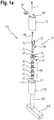
- illustrated golf club 100 is configured as a putter and includes a shaft 105, a handle 110 disposed at one end of the shaft 105, a head 120 located at the other end of the shaft Shaft 105 is arranged, and a device 10, which serves for repairing bumps in a arranged on a ground green area and is attached to the handle 110.
- the device 10 comprises an insertion element 20 designed as a pitch fork, a cover element 50 covering the insertion element 20, a connecting element 40 and a fastening element 30, 90.
- the insertion element 20 has a flat holding portion 21 and projecting from the holding portion 21 tines 22.
- the tines 22 are curved.
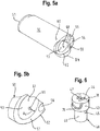
- the connecting element 40 has an upper side 41 facing away from the fastening element 30, 90 and a lower side 42 facing the fastening element 30, 90 and is seated, in particular also Fig. 6 can be seen, from an upper part and a lower part together, which are each designed circular cylindrical.
- the lower part, which faces the fastening element 30, 90, has a smaller diameter than the upper part.
- the connecting element 40 has a first opening 44, in which the holding section 21 is arranged.
- a second opening 45 is arranged in the region of the lower part of the connecting element 40 and extends from a lateral surface 49 up to the first opening 44.
- the second opening 45 is provided with an internal thread into which a securing screw 46 designed as a grub screw is screwed to fix the holding portion 21 in the first opening 44.
- the fastening element 90 and the connecting element 40 are connected to each other in a first embodiment of the device 10 by a screw connection which comprises a screw 80 and a nut 81.
- the connecting element 40 is provided with a passage opening 47 extending from the upper side 41 to the lower side 42.
- the fastener 90 is located in the in the FIGS. 1a and 1b shown first embodiment of the device 10 of a plurality of clamping elements 91 and pressure elements 92 together, which alternately in axial Direction L are arranged one behind the other.
- the clamping elements 91 and the pressure elements 92 are clamped by the screw 80, 81 against each other.
- pressure element 92 located on the bottom in the axial direction L pressure element 92 is a contact surface 34 for the nut 81.
- the clamping elements 91 which consist of a deformable material, such as rubber or plastic, are acted upon by the pressure elements 91 in the axial direction L and compressed.
- the compression causes a bulge 93, which penetrates through slots formed between the pressure elements 92 and in this way on the inner surface 113 of a cavity 112 of the handle 110 causes a frictional connection, which reliably holds the device 10 to the handle 110.
- the tubular cavity 112, as in particular Fig. 1b can be seen, formed by the wall of the shaft 105 in the region of the handle 110, so that there is a secure frictional connection due to the strength of the wall.
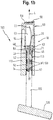
- the cover element 50 has an upper side 51 facing away from the handle 110 and a lower side 52 facing the handle 110.
- a cavity 53 opening on the underside 52 accommodates the insertion element 20 and the upper part of the connecting element 40.
- the lower part of the connecting element 40 comes to rest in the cavity 112.
- Parallel to the cavity 53 extend in the axial direction L cavities 54, 55, 56, in particular also Fig. 5a to recognize.
- the cover element 50 has on the underside 52 a contact surface 57 which bears against an end face 111 of the handle 110 when the cover element 50 is connected to the connecting element 40.
- the cavities 54, 55, 56 which influence the deformability of the cover element 50, open at the contact surface 57 and thus at the same time influence the sliding friction between the contact surface 57 and the end face 111.
- the cavities 54, 55, 56 thus provide 57 points in the area of the contact surface a friction-reducing surface.
- the cover member 50 has a holder 58 which serves to hold a chip-shaped ball marker 59.
- a fastening element 30 which faces away from the connecting element 40 top 31 and the connecting element 40 facing away Bottom 32 has.
- the fastening element 30 is designed circular-cylindrical and has a peripheral surface 33.
- the connecting element 40 forms a clamping surface 48 which extends at a first angle ⁇ obliquely to the axial direction L.
- the fastener 30 forms at the top 31 a clamping surface 38 having a center Z and extending at a second angle ⁇ oblique to the axial direction L.
- the first angle ⁇ and the second angle ⁇ form minor angle, so complement each other to 180 °.
- the first angle ⁇ is about 150 ° and the second angle ⁇ is about 30 °.
- the clamping surfaces 48, 38 are therefore parallel. Depending on the application, however, the clamping surfaces 38, 48 may also include an angle.
- the fastener 30 extends from the top 31 to the nut 81 supporting contact surface 34, a slot 35 which receives the screw 80 with a play in the radial direction, ie in a direction perpendicular to the axial direction L, and outside the center Z of the clamping surface 38 is arranged.
- the contact surface 34 is formed by a shoulder 36 in a recess 37 on the bottom 32. The recess 37 receives the nut 81 secured against rotation.
- the resulting offset V causes the lateral surface 49 of the connecting element 40 and the circumferential surface 33 of the fastening element (30) to be pressed against the inner surface 113, resulting in a frictional connection between the fastening element 30 and the connecting element 40 on the one hand and the handle 110 on the other hand results.
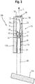
- the fastening element 30 and the connecting element 40 are designed in one piece.
- the circumferential surface 33 of the fastening element 30 and the lateral surface 49 in the region of the lower part of the connecting element 40 form a fastening surface, which rests against the inner surface 113 and - for example, coated with an adhesive - a material connection between the fastening element 30 and the connecting element 40 on the one hand and the handle 110 causes on the other hand.
- the different embodiments of the device 10 differ in the design of the fastener 30 and the manner of attachment of the device 10 to the golf club 100.
- the embodiments have the embodiment of the cover member 50 and the releasable connection of the cover member 50 with the connecting member 40 by means of a bayonet catch.
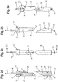
- the connecting element 40 has two depressions 70, which are designed as a groove on regions of the lateral surface 43 facing away from one another.
- the cover element 50 has two projections or cams 60, which are formed on an inner surface 61 of the cavity 53 and, when the cover element 50 is plugged onto the connecting element 40, engage in the recesses 70.
- FIGS. 5a and 5b indicate the protrusions 60 are at a distance Av from the contact surface 57th
- the recesses 70 each follow a trajectory K, in particular Fig. 4b can be seen, extending from an opening at the top 41 beginning portion 71 to an end stop 73 ending at an end portion 72.
- the trajectory K In the transition region from the initial section 71 to the end section 72, the trajectory K has a local low point T, which is located at a distance A T from the end face 111 and in whose area the sign of the slope of the trajectory K changes.
- the trajectory K is decreasing and rises after reaching the low point T in the region of the end section 72.
- the slope of the trajectory K decreases in the end portion 72.
- the trajectory K is substantially parallel to the end face 111.
- the recesses 70 are therefore similar to a recumbent L.
- the cover member 50 completes the handle 110 and, therefore, is made of a material that meets the golfer's haptic and hardness requirements of a handle, such as rubber. Rubber is known to be an elastically deformable material. Accordingly, the cover element 50 can be compressed slightly when placed on the end face 111, whereby a restoring force in the axial direction L is generated. This is exploited when the cover member 50 is connected by means of a plug-and-turn movement with the connecting member 40, as shown in the FIGS. 7a to 8c can be seen.
- FIGS. 7a, 7b and 7c the cover element 50 is shown after being attached to the connecting element 40.
- the cover member 50 is rotated in this unlocked position by approximately 90 ° to the in the FIGS. 8a, 8b and 8c shown latched position in which the projection 60 abuts the end stop 73, in particular Fig. 7a to recognize.
- the projection 60 has penetrated a little way into the depression 70, which runs almost vertically at the beginning of the start section 71, as in particular Fig. 7c to recognize.
- the cover element 50 approaches by the rotational movement of the end face 111 of the handle 110.
- the contact surface 57 bears against the end face 111. A movement of the projection 60 beyond the low point T therefore requires a compression of the cover element 50.
- the size of the compression results from the difference between the distance A T and the distance that the straight running point of the trajectory K to the end face 111 has. Accordingly, the compression in the region of the low point T, which is located at a minimum distance A T to the end face 11, the largest, and decreases to the end stop 73, which is located at a distance A E to the end face 11 back out.
- the restoring force resulting from the compression of the cover element 50 in the axial direction L presses the projection 60 at the lower edge of the recess 70 in the axial direction L.
- the high point H which is located just before the end stop 73 and after reaching the trajectory K to the end stop 73 again slightly decreases, thus ensuring that the projection 60 form and frictionally held on the end stop 73, in particular Fig. 8c to recognize.
- the cover member 50 and the connecting member 40 are, when the projection 60 abuts the end stop 73, thereby reliably locked.
- the device 10 described above supplements the golf club 100 with a repair tool that is stowed away reliably by the cover element 50 when not in use.
- the bayonet catch resulting from the engagement of the projection 60 in the recess 70 and the formation of the recess 70 as a trajectory K extending along the lateral surface 43 makes it possible to releasably connect the cover element 50 to the connecting element 40 by means of an easily executed plug-and-turn movement. and easy to solve again by a reverse rotation.
- the bayonet lock in the locked position of the cover member 50 ensures a positive and non-positive grip of the projection 60 in the recess 70, which prevents unintentional release of the cover member 50 and thus does not affect the handling of the golf club 100.
Landscapes
- Health & Medical Sciences (AREA)
- General Health & Medical Sciences (AREA)
- Physical Education & Sports Medicine (AREA)
- Life Sciences & Earth Sciences (AREA)
- Engineering & Computer Science (AREA)
- Mechanical Engineering (AREA)
- Soil Sciences (AREA)
- Environmental Sciences (AREA)
- Golf Clubs (AREA)
Claims (15)
- Dispositif pour rectifier des irrégularités de surface d'une pelouse disposée sur un sol, le dispositif (10) étant apte à être fixé sur une poignée (110) d'un club de golf (100), comportant :un élément de fixation (30 ; 90) au moyen duquel le dispositif (10) est susceptible d'être fixé sur la poignée (110) ;un élément d'introduction (20) qui est apte à être introduit dans le sol pour rectifier les irrégularités de surface ;un élément de recouvrement (50) pour recouvrir l'élément d'introduction (20), qui comprend une face supérieure (51) et une face inférieure (52) et au moins une cavité (53, 54, 55, 56) qui débouche sur la face inférieure (52) ; etun élément de liaison (40) qui présente une surface enveloppe (43, 49) et qui est susceptible d'être relié de façon détachable à l'élément de recouvrement (50) au moyen d'une fermeture à baïonnette permettant un mouvement d'enfichage/rotation ;dans lequella cavité (53) est apte à recevoir l'élément d'introduction (20) et l'élément de liaison (40) ;pour former la fermeture à baïonnette, l'élément de liaison (40) présente au moins un renfoncement (70) qui présente une portion initiale (71) et une portion terminale (72), et l'élément de recouvrement (50) présente au moins une saillie (60) qui s'engage dans le renfoncement (70) et qui est mobile depuis la portion initiale (71) jusque dans la portion terminale (72) ;la saillie (60) est mobile à l'encontre de l'effet d'une force de rappel agissant dans une direction axiale (L) depuis la portion initiale (71) dans laquelle l'élément de recouvrement (50) est séparable de l'élément de liaison (40), jusqu'à la portion terminale (72) dans laquelle la saillie (60) est retenue dans le renfoncement (70) par coopération de formes et de forces ;le renfoncement (70) est réalisé sous forme de gorge qui s'étend le long de la surface enveloppe (43) en suivant une trajectoire (K) ; etla trajectoire (K) présente son point le plus bas (T) dans la zone de transition de la portion initiale (71) à la portion terminale (72).
- Dispositif pour rectifier des irrégularités de surface d'une pelouse disposée sur un sol, le dispositif (10) étant apte à être fixé sur une poignée (110) d'un club de golf (100), comportant :un élément de fixation (30 ; 90) au moyen duquel le dispositif (10) est susceptible d'être fixé sur la poignée (110) ;un élément d'introduction (20) qui est apte à être introduit dans le sol pour rectifier les irrégularités de surface ;un élément de recouvrement (50) pour recouvrir l'élément d'introduction (20) qui comprend une face supérieure (51) et une face inférieure (52) et au moins une cavité (53, 54, 55, 56) qui débouche sur la face inférieure (52) ; etun élément de liaison (40) qui présente une surface enveloppe (43, 49) et qui est susceptible d'être relié de façon détachable à l'élément de recouvrement (50) au moyen d'une fermeture à baïonnette permettant un mouvement d'enfichage/rotation ;dans lequella cavité (53) est apte à recevoir l'élément d'introduction (20) et l'élément de liaison (40), et présente une surface intérieure (61) ;pour former la fermeture à baïonnette, l'élément de recouvrement (50) présente au moins un renfoncement (70) qui présente une portion initiale (71) et une portion terminale (72), et l'élément de liaison (40) présente au moins une saillie (60) qui s'engage dans le renfoncement (70) et qui est mobile depuis la portion initiale (71) jusque dans la portion terminale (72) ;la saillie (60) est mobile à l'encontre de l'effet d'une force de rappel agissant dans une direction axiale (L) depuis la portion initiale (71) dans laquelle l'élément de recouvrement (50) est séparable de l'élément de liaison (40), jusqu'à la portion terminale (72) dans laquelle la saillie (60) est retenue dans le renfoncement (70) par coopération de formes et de forces ;le renfoncement (70) est réalisé sous forme de gorge qui s'étend le long de la surface intérieure (61) en suivant une trajectoire (K) ; etla trajectoire (K) présente son point le plus bas (T) dans la zone de transition de la portion initiale (71) à la portion terminale (72).
- Dispositif selon la revendication 1 ou 2, caractérisé en ce que la surface enveloppe (43, 49) est cylindrique, en particulier cylindrique à base circulaire, et l'élément de liaison (40) se compose de préférence d'une partie supérieure et d'une partie inférieure qui présente un diamètre inférieur à celui de la partie supérieure.
- Dispositif selon la revendication 1, 2 ou 3, caractérisé en ce qu'au moins dans la zone du point le plus bas (T), le signe de la pente de la trajectoire (K) dans la portion initiale (71) est inverse au signe de la pente dans la portion terminale (72), et de préférence une butée d'extrémité (73) pour la saillie (60) délimite la portion terminale (72), la pente de la trajectoire (K) dans la portion terminale (72) décroissant vers la butée d'extrémité (73).
- Dispositif selon l'une des revendications 1 à 4, caractérisé en ce que l'élément de recouvrement (50) est fabriqué au moins localement, en particulier dans la zone de la saillie (60) ou du renfoncement (70), d'un matériau élastiquement déformable, et l'élément de recouvrement (50) présente en outre sur la face inférieure (52) une surface de contact (57) apte à venir en appui contre une surface frontale (111) de la poignée (110) d'un club de golf (100), la surface de contact (57) présentant de préférence au moins localement des endroits (54, 55, 56) pourvus d'une surface réduisant la friction.
- Dispositif selon la revendication 5, caractérisé en ce que l'élément de recouvrement (50) comprend sur la face supérieure (51) un élément de retenue (58) qui est apte à retenir un marqueur de balle (59) en particulier en forme de plaquette.
- Dispositif selon l'une des revendications 1 à 6, caractérisé en ce que l'élément d'introduction (20) comprend une portion de retenue (21) qui est de préférence réalisée plane, et des dents (22) qui font saillie de la portion de retenue (21) qui sont de préférence réalisées bombées, l'élément de liaison (40) présentant sur la face supérieure (41) une première ouverture (44) dans laquelle est agencée la portion de retenue (21), l'élément de liaison (40) présentant de préférence une seconde ouverture (45) sur la surface enveloppe (43), dans laquelle est logée une vis de blocage (46) fixant la portion de retenue (21).
- Dispositif selon l'une des revendications 1 à 7, caractérisé en ce que l'élément de fixation (30 ; 90) et l'élément de liaison (40) sont reliés entre eux par une liaison vissée (80, 81), l'élément de liaison (40) étant pourvu de préférence d'une ouverture traversante (47) s'étendant de la face supérieure (41) jusqu'à la face inférieure (42) et destinée à recevoir une vis (80) qui s'étend en particulier dans la direction axiale (L), et de plus l'élément de fixation (30) possède en outre de préférence une face supérieure (31) et une face inférieure (32) et est pourvu d'une surface d'appui (34) réalisée en particulier sur la face inférieure (32) pour soutenir un écrou (81) coopérant avec la vis (80).
- Dispositif selon la revendication 8, caractérisé en ce que sur la face inférieure (42) l'élément de liaison (40) présente une surface de coincement (48) qui s'étend sous un premier angle (□) en oblique par rapport à la direction axiale (L), et en ce que sur la face supérieure (31) l'élément de fixation (30) présente une surface de coincement (38) qui présente un centre (Z) et qui s'étend sous un second angle (□) en oblique par rapport à la direction axiale (L), et de préférence le premier angle (□) et le second angle (□) forment des angles adjacents, et de plus de préférence le premier angle (□) est compris entre 130° et 170°, en particulier entre 140° et 160°, et le second angle (□) est compris entre 10° et 50°, en particulier entre 20° et 40°, l'élément de fixation (30) présentant un trou oblong (35) qui s'étend depuis la face supérieure (31) jusqu'à la surface d'appui (34) dans la direction axiale (L) et qui reçoit la vis (80) avec jeu radial et qui est disposé à l'extérieur du centre (Z) de la surface de coincement (38).
- Dispositif selon la revendication 8, caractérisé en ce que l'élément de fixation (90) comprend au moins un élément de coincement (91) constitué d'un matériau déformable, et au moins un élément de compression (92) sollicitant l'élément de coincement (91), l'élément de coincement (91) et l'élément de compression (92) étant serrés l'un contre l'autre de préférence au moyen de la liaison vissée (80, 81).
- Dispositif selon l'une des revendications 1 à 7, caractérisé en ce que l'élément de fixation (30) et l'élément de liaison (40) sont réalisés d'un seul tenant, et l'élément de fixation (30) présente de préférence une surface périphérique (33) qui est apte à être fixée par coopération de matières sur une surface intérieure (113) de la poignée (110).
- Club de golf, en particulier "putter", comportant :un manche (105),une poignée (110) qui est agencée à une extrémité du manche (105), etune tête (120) qui est agencée à l'autre extrémité du manche (105), caractérisé par un dispositif (10) selon l'une des revendications 1 à 11, qui est fixé sur la poignée (110).
- Club de golf selon la revendication 12, caractérisé en ce que la poignée (110) présente une cavité (112) qui possède une surface intérieure (113) et dans laquelle est/sont agencé(s) l'élément de fixation (30) et/ou l'élément de liaison (40).
- Club de golf selon la revendication 13, caractérisé en ce que l'élément de fixation (30) est relié par coopération de forces à la poignée (110), la surface périphérique (33) de l'élément de fixation (30) ou l'élément de coincement (91) prenant appui de préférence par coopération de forces contre la surface intérieure (113) de la poignée (110).
- Club de golf selon la revendication 13, caractérisé en ce que l'élément de fixation (30) est relié par coopération de matières avec la poignée (110), et la surface périphérique (33) de l'élément de fixation (30) prend appui de préférence par coopération de matières contre la surface intérieure (113) de la poignée (110).
Applications Claiming Priority (2)
| Application Number | Priority Date | Filing Date | Title |
|---|---|---|---|
| ATA50029/2014A AT515395B1 (de) | 2014-01-17 | 2014-01-17 | Vorrichtung zum Ausbessern von Unebenheiten in einer auf einem Erdboden angeordneten Grünfläche |
| PCT/EP2015/050796 WO2015107160A1 (fr) | 2014-01-17 | 2015-01-16 | Dispositif pour corriger des irrégularités dans une surface verte située sur un terrain et club de golf pourvu d'un tel dispositif |
Publications (2)
| Publication Number | Publication Date |
|---|---|
| EP2934708A1 EP2934708A1 (fr) | 2015-10-28 |
| EP2934708B1 true EP2934708B1 (fr) | 2016-12-14 |
Family
ID=52358781
Family Applications (1)
| Application Number | Title | Priority Date | Filing Date |
|---|---|---|---|
| EP15700585.1A Not-in-force EP2934708B1 (fr) | 2014-01-17 | 2015-01-16 | Dispositif pour rectifier des irrégularités de surface d'une pelouse, et club de golf muni d'un tel dispositif |
Country Status (4)
| Country | Link |
|---|---|
| US (1) | US20160332045A1 (fr) |
| EP (1) | EP2934708B1 (fr) |
| AT (1) | AT515395B1 (fr) |
| WO (1) | WO2015107160A1 (fr) |
Families Citing this family (2)
| Publication number | Priority date | Publication date | Assignee | Title |
|---|---|---|---|---|
| WO2017059456A1 (fr) * | 2015-10-01 | 2017-04-06 | Trojan Daniel G | Accessoire de golf présentant une meilleure visibilité et une meilleure fonctionnalité |
| US20190240551A1 (en) * | 2018-02-02 | 2019-08-08 | Michael Kristoff | Golf green repair tool system |
Family Cites Families (13)
| Publication number | Priority date | Publication date | Assignee | Title |
|---|---|---|---|---|
| GB190416896A (en) * | 1904-08-02 | 1905-06-08 | Frederick James Brown | Improvements in or relating to Golf-sticks and Parts therefor, also in Means for Carrying the same. |
| GB2220576A (en) * | 1988-07-15 | 1990-01-17 | Iain James Robinson | Dismantleable golf clubs |
| US4925190A (en) * | 1989-04-24 | 1990-05-15 | Learned Thomas J | Combination golf club and turf repair tool |
| US4955609A (en) * | 1989-09-01 | 1990-09-11 | Kassen Albert D | Golf club with green surface repair device |
| US5305999A (en) * | 1992-01-16 | 1994-04-26 | John Tate | Golf accessory |
| US5277425A (en) * | 1992-09-11 | 1994-01-11 | Greenskeeper Corp. Of Dutchess | Golf club including turf repair tool |
| US5511785A (en) * | 1994-12-06 | 1996-04-30 | Rusin, Jr.; Richard E. | Golf club with shaft recessing divot tool |
| US6244356B1 (en) * | 2000-12-08 | 2001-06-12 | John Luna | Ball mark repair tool |
| GB0030665D0 (en) * | 2000-12-15 | 2001-01-31 | Richards Paul | A golf club |
| US6620062B2 (en) * | 2001-12-08 | 2003-09-16 | Taylor Cutlery, Llc | Divot repair tool |
| US7731601B2 (en) * | 2005-09-14 | 2010-06-08 | Penton Hugh V | Pitch-mark repair tool for a golf club |
| US20070298900A1 (en) * | 2006-06-21 | 2007-12-27 | Johnson J W | Multipurpose golf assembly |
| US7351158B1 (en) * | 2007-02-05 | 2008-04-01 | Bronsveld Ernest B | Golf club with divot repair tool |
-
2014
- 2014-01-17 AT ATA50029/2014A patent/AT515395B1/de not_active IP Right Cessation
-
2015
- 2015-01-16 WO PCT/EP2015/050796 patent/WO2015107160A1/fr active Application Filing
- 2015-01-16 EP EP15700585.1A patent/EP2934708B1/fr not_active Not-in-force
- 2015-01-16 US US15/111,598 patent/US20160332045A1/en not_active Abandoned
Also Published As
| Publication number | Publication date |
|---|---|
| AT515395B1 (de) | 2017-03-15 |
| EP2934708A1 (fr) | 2015-10-28 |
| US20160332045A1 (en) | 2016-11-17 |
| AT515395A1 (de) | 2015-08-15 |
| WO2015107160A1 (fr) | 2015-07-23 |
Similar Documents
| Publication | Publication Date | Title |
|---|---|---|
| EP3288411B1 (fr) | Système de changement de rondelle pour la randonnée | |
| DE10030961A1 (de) | Vorrichtung zum Trainieren von Bewegungsabläufen | |
| WO2000029079A1 (fr) | Baton tel que baton de ski, baton de randonnee, etc. | |
| WO2016102173A1 (fr) | Talon de chaussure interchangeable | |
| EP2934708B1 (fr) | Dispositif pour rectifier des irrégularités de surface d'une pelouse, et club de golf muni d'un tel dispositif | |
| DE102010017079A1 (de) | Golfschläger | |
| WO2016198493A1 (fr) | Dispositif pour réparer des marques laissées par des approches pitchées | |
| DE2923873A1 (de) | Vorrichtung zur einfuehrung in den handgriff eines spiel- oder sportgeraets zum zwecke der verbesserung der handlichkeit dieser geraete | |
| WO2009129832A1 (fr) | Club de golf, en particulier putter de golf | |
| DE3026452A1 (de) | Sohle fuer sportschuhe, insbesondere fussballschuhe | |
| DE102011120059A1 (de) | Griff für einen Golfputter und Golfputter | |
| DE2458581A1 (de) | Tennisschlaeger | |
| DE102016120091B4 (de) | Fangvorrichtung für Golftee | |
| DE2458572A1 (de) | Tennisschlaeger | |
| DE3332291A1 (de) | Ballschlaeger, insbesondere tennisschlaeger | |
| AT514453B1 (de) | Aufsatz für ein Sportgerät speziell für Putter (Golf) | |
| DE102011055261B4 (de) | Aufsatz für einen Schuh mit reibungserhöhender Oberfläche | |
| DE2444304A1 (de) | Tennisschlaeger | |
| WO2006048176A1 (fr) | Auxiliaire de tee pour balles de golf | |
| DE202005008740U1 (de) | Tee-Eindrücker | |
| DE3738961C2 (de) | Verstellbarer Eisstockstiel | |
| DE102016120092A1 (de) | Individual Tee | |
| WO2004052475A1 (fr) | Dispositif d'entrainement au golf | |
| DE202008014045U1 (de) | Pitchstab | |
| DE10331222A1 (de) | Golfteekombination |
Legal Events
| Date | Code | Title | Description |
|---|---|---|---|
| PUAI | Public reference made under article 153(3) epc to a published international application that has entered the european phase |
Free format text: ORIGINAL CODE: 0009012 |
|
| 17P | Request for examination filed |
Effective date: 20150722 |
|
| AK | Designated contracting states |
Kind code of ref document: A1 Designated state(s): AL AT BE BG CH CY CZ DE DK EE ES FI FR GB GR HR HU IE IS IT LI LT LU LV MC MK MT NL NO PL PT RO RS SE SI SK SM TR |
|
| AX | Request for extension of the european patent |
Extension state: BA ME |
|
| 17Q | First examination report despatched |
Effective date: 20151222 |
|
| RIC1 | Information provided on ipc code assigned before grant |
Ipc: A63B 60/16 20150101ALI20160511BHEP Ipc: A63B 57/50 20150101ALI20160511BHEP Ipc: A63B 53/14 20060101AFI20160511BHEP |
|
| GRAJ | Information related to disapproval of communication of intention to grant by the applicant or resumption of examination proceedings by the epo deleted |
Free format text: ORIGINAL CODE: EPIDOSDIGR1 |
|
| GRAP | Despatch of communication of intention to grant a patent |
Free format text: ORIGINAL CODE: EPIDOSNIGR1 |
|
| DAX | Request for extension of the european patent (deleted) | ||
| INTG | Intention to grant announced |
Effective date: 20160707 |
|
| RIN1 | Information on inventor provided before grant (corrected) |
Inventor name: HOFMANN, WERNER Inventor name: LUMPI, HANSJOERG |
|
| GRAS | Grant fee paid |
Free format text: ORIGINAL CODE: EPIDOSNIGR3 |
|
| GRAA | (expected) grant |
Free format text: ORIGINAL CODE: 0009210 |
|
| AK | Designated contracting states |
Kind code of ref document: B1 Designated state(s): AL AT BE BG CH CY CZ DE DK EE ES FI FR GB GR HR HU IE IS IT LI LT LU LV MC MK MT NL NO PL PT RO RS SE SI SK SM TR |
|
| REG | Reference to a national code |
Ref country code: GB Ref legal event code: FG4D Free format text: NOT ENGLISH |
|
| REG | Reference to a national code |
Ref country code: CH Ref legal event code: EP |
|
| REG | Reference to a national code |
Ref country code: IE Ref legal event code: FG4D Free format text: LANGUAGE OF EP DOCUMENT: GERMAN |
|
| REG | Reference to a national code |
Ref country code: AT Ref legal event code: REF Ref document number: 853050 Country of ref document: AT Kind code of ref document: T Effective date: 20170115 |
|
| REG | Reference to a national code |
Ref country code: DE Ref legal event code: R096 Ref document number: 502015000396 Country of ref document: DE |
|
| PG25 | Lapsed in a contracting state [announced via postgrant information from national office to epo] |
Ref country code: LV Free format text: LAPSE BECAUSE OF FAILURE TO SUBMIT A TRANSLATION OF THE DESCRIPTION OR TO PAY THE FEE WITHIN THE PRESCRIBED TIME-LIMIT Effective date: 20161214 |
|
| REG | Reference to a national code |
Ref country code: LT Ref legal event code: MG4D |
|
| REG | Reference to a national code |
Ref country code: NL Ref legal event code: MP Effective date: 20161214 |
|
| PG25 | Lapsed in a contracting state [announced via postgrant information from national office to epo] |
Ref country code: SE Free format text: LAPSE BECAUSE OF FAILURE TO SUBMIT A TRANSLATION OF THE DESCRIPTION OR TO PAY THE FEE WITHIN THE PRESCRIBED TIME-LIMIT Effective date: 20161214 Ref country code: NO Free format text: LAPSE BECAUSE OF FAILURE TO SUBMIT A TRANSLATION OF THE DESCRIPTION OR TO PAY THE FEE WITHIN THE PRESCRIBED TIME-LIMIT Effective date: 20170314 Ref country code: GR Free format text: LAPSE BECAUSE OF FAILURE TO SUBMIT A TRANSLATION OF THE DESCRIPTION OR TO PAY THE FEE WITHIN THE PRESCRIBED TIME-LIMIT Effective date: 20170315 Ref country code: LT Free format text: LAPSE BECAUSE OF FAILURE TO SUBMIT A TRANSLATION OF THE DESCRIPTION OR TO PAY THE FEE WITHIN THE PRESCRIBED TIME-LIMIT Effective date: 20161214 |
|
| PG25 | Lapsed in a contracting state [announced via postgrant information from national office to epo] |
Ref country code: HR Free format text: LAPSE BECAUSE OF FAILURE TO SUBMIT A TRANSLATION OF THE DESCRIPTION OR TO PAY THE FEE WITHIN THE PRESCRIBED TIME-LIMIT Effective date: 20161214 Ref country code: RS Free format text: LAPSE BECAUSE OF FAILURE TO SUBMIT A TRANSLATION OF THE DESCRIPTION OR TO PAY THE FEE WITHIN THE PRESCRIBED TIME-LIMIT Effective date: 20161214 Ref country code: FI Free format text: LAPSE BECAUSE OF FAILURE TO SUBMIT A TRANSLATION OF THE DESCRIPTION OR TO PAY THE FEE WITHIN THE PRESCRIBED TIME-LIMIT Effective date: 20161214 Ref country code: BE Free format text: LAPSE BECAUSE OF NON-PAYMENT OF DUE FEES Effective date: 20170131 |
|
| PG25 | Lapsed in a contracting state [announced via postgrant information from national office to epo] |
Ref country code: NL Free format text: LAPSE BECAUSE OF FAILURE TO SUBMIT A TRANSLATION OF THE DESCRIPTION OR TO PAY THE FEE WITHIN THE PRESCRIBED TIME-LIMIT Effective date: 20161214 |
|
| PG25 | Lapsed in a contracting state [announced via postgrant information from national office to epo] |
Ref country code: SK Free format text: LAPSE BECAUSE OF FAILURE TO SUBMIT A TRANSLATION OF THE DESCRIPTION OR TO PAY THE FEE WITHIN THE PRESCRIBED TIME-LIMIT Effective date: 20161214 Ref country code: CZ Free format text: LAPSE BECAUSE OF FAILURE TO SUBMIT A TRANSLATION OF THE DESCRIPTION OR TO PAY THE FEE WITHIN THE PRESCRIBED TIME-LIMIT Effective date: 20161214 Ref country code: RO Free format text: LAPSE BECAUSE OF FAILURE TO SUBMIT A TRANSLATION OF THE DESCRIPTION OR TO PAY THE FEE WITHIN THE PRESCRIBED TIME-LIMIT Effective date: 20161214 Ref country code: IS Free format text: LAPSE BECAUSE OF FAILURE TO SUBMIT A TRANSLATION OF THE DESCRIPTION OR TO PAY THE FEE WITHIN THE PRESCRIBED TIME-LIMIT Effective date: 20170414 Ref country code: EE Free format text: LAPSE BECAUSE OF FAILURE TO SUBMIT A TRANSLATION OF THE DESCRIPTION OR TO PAY THE FEE WITHIN THE PRESCRIBED TIME-LIMIT Effective date: 20161214 |
|
| REG | Reference to a national code |
Ref country code: DE Ref legal event code: R119 Ref document number: 502015000396 Country of ref document: DE |
|
| PG25 | Lapsed in a contracting state [announced via postgrant information from national office to epo] |
Ref country code: PT Free format text: LAPSE BECAUSE OF FAILURE TO SUBMIT A TRANSLATION OF THE DESCRIPTION OR TO PAY THE FEE WITHIN THE PRESCRIBED TIME-LIMIT Effective date: 20170414 Ref country code: PL Free format text: LAPSE BECAUSE OF FAILURE TO SUBMIT A TRANSLATION OF THE DESCRIPTION OR TO PAY THE FEE WITHIN THE PRESCRIBED TIME-LIMIT Effective date: 20161214 Ref country code: SM Free format text: LAPSE BECAUSE OF FAILURE TO SUBMIT A TRANSLATION OF THE DESCRIPTION OR TO PAY THE FEE WITHIN THE PRESCRIBED TIME-LIMIT Effective date: 20161214 Ref country code: BG Free format text: LAPSE BECAUSE OF FAILURE TO SUBMIT A TRANSLATION OF THE DESCRIPTION OR TO PAY THE FEE WITHIN THE PRESCRIBED TIME-LIMIT Effective date: 20170314 Ref country code: ES Free format text: LAPSE BECAUSE OF FAILURE TO SUBMIT A TRANSLATION OF THE DESCRIPTION OR TO PAY THE FEE WITHIN THE PRESCRIBED TIME-LIMIT Effective date: 20161214 Ref country code: IT Free format text: LAPSE BECAUSE OF FAILURE TO SUBMIT A TRANSLATION OF THE DESCRIPTION OR TO PAY THE FEE WITHIN THE PRESCRIBED TIME-LIMIT Effective date: 20161214 |
|
| PG25 | Lapsed in a contracting state [announced via postgrant information from national office to epo] |
Ref country code: MC Free format text: LAPSE BECAUSE OF FAILURE TO SUBMIT A TRANSLATION OF THE DESCRIPTION OR TO PAY THE FEE WITHIN THE PRESCRIBED TIME-LIMIT Effective date: 20161214 |
|
| PLBE | No opposition filed within time limit |
Free format text: ORIGINAL CODE: 0009261 |
|
| STAA | Information on the status of an ep patent application or granted ep patent |
Free format text: STATUS: NO OPPOSITION FILED WITHIN TIME LIMIT |
|
| REG | Reference to a national code |
Ref country code: FR Ref legal event code: ST Effective date: 20170929 |
|
| PG25 | Lapsed in a contracting state [announced via postgrant information from national office to epo] |
Ref country code: FR Free format text: LAPSE BECAUSE OF NON-PAYMENT OF DUE FEES Effective date: 20170214 |
|
| REG | Reference to a national code |
Ref country code: IE Ref legal event code: MM4A |
|
| 26N | No opposition filed |
Effective date: 20170915 |
|
| PG25 | Lapsed in a contracting state [announced via postgrant information from national office to epo] |
Ref country code: LU Free format text: LAPSE BECAUSE OF NON-PAYMENT OF DUE FEES Effective date: 20170116 Ref country code: DE Free format text: LAPSE BECAUSE OF NON-PAYMENT OF DUE FEES Effective date: 20170801 Ref country code: DK Free format text: LAPSE BECAUSE OF FAILURE TO SUBMIT A TRANSLATION OF THE DESCRIPTION OR TO PAY THE FEE WITHIN THE PRESCRIBED TIME-LIMIT Effective date: 20161214 |
|
| REG | Reference to a national code |
Ref country code: BE Ref legal event code: MM Effective date: 20170131 |
|
| PG25 | Lapsed in a contracting state [announced via postgrant information from national office to epo] |
Ref country code: IE Free format text: LAPSE BECAUSE OF NON-PAYMENT OF DUE FEES Effective date: 20170116 Ref country code: SI Free format text: LAPSE BECAUSE OF FAILURE TO SUBMIT A TRANSLATION OF THE DESCRIPTION OR TO PAY THE FEE WITHIN THE PRESCRIBED TIME-LIMIT Effective date: 20161214 |
|
| REG | Reference to a national code |
Ref country code: CH Ref legal event code: PL |
|
| PG25 | Lapsed in a contracting state [announced via postgrant information from national office to epo] |
Ref country code: MT Free format text: LAPSE BECAUSE OF FAILURE TO SUBMIT A TRANSLATION OF THE DESCRIPTION OR TO PAY THE FEE WITHIN THE PRESCRIBED TIME-LIMIT Effective date: 20161214 |
|
| PG25 | Lapsed in a contracting state [announced via postgrant information from national office to epo] |
Ref country code: CH Free format text: LAPSE BECAUSE OF NON-PAYMENT OF DUE FEES Effective date: 20180131 Ref country code: LI Free format text: LAPSE BECAUSE OF NON-PAYMENT OF DUE FEES Effective date: 20180131 |
|
| PG25 | Lapsed in a contracting state [announced via postgrant information from national office to epo] |
Ref country code: HU Free format text: LAPSE BECAUSE OF FAILURE TO SUBMIT A TRANSLATION OF THE DESCRIPTION OR TO PAY THE FEE WITHIN THE PRESCRIBED TIME-LIMIT; INVALID AB INITIO Effective date: 20150116 |
|
| GBPC | Gb: european patent ceased through non-payment of renewal fee |
Effective date: 20190116 |
|
| PG25 | Lapsed in a contracting state [announced via postgrant information from national office to epo] |
Ref country code: CY Free format text: LAPSE BECAUSE OF FAILURE TO SUBMIT A TRANSLATION OF THE DESCRIPTION OR TO PAY THE FEE WITHIN THE PRESCRIBED TIME-LIMIT Effective date: 20161214 |
|
| PG25 | Lapsed in a contracting state [announced via postgrant information from national office to epo] |
Ref country code: MK Free format text: LAPSE BECAUSE OF FAILURE TO SUBMIT A TRANSLATION OF THE DESCRIPTION OR TO PAY THE FEE WITHIN THE PRESCRIBED TIME-LIMIT Effective date: 20161214 |
|
| PG25 | Lapsed in a contracting state [announced via postgrant information from national office to epo] |
Ref country code: GB Free format text: LAPSE BECAUSE OF NON-PAYMENT OF DUE FEES Effective date: 20190116 |
|
| PG25 | Lapsed in a contracting state [announced via postgrant information from national office to epo] |
Ref country code: TR Free format text: LAPSE BECAUSE OF FAILURE TO SUBMIT A TRANSLATION OF THE DESCRIPTION OR TO PAY THE FEE WITHIN THE PRESCRIBED TIME-LIMIT Effective date: 20161214 |
|
| PG25 | Lapsed in a contracting state [announced via postgrant information from national office to epo] |
Ref country code: AL Free format text: LAPSE BECAUSE OF FAILURE TO SUBMIT A TRANSLATION OF THE DESCRIPTION OR TO PAY THE FEE WITHIN THE PRESCRIBED TIME-LIMIT Effective date: 20161214 |
|
| REG | Reference to a national code |
Ref country code: AT Ref legal event code: MM01 Ref document number: 853050 Country of ref document: AT Kind code of ref document: T Effective date: 20200116 |
|
| PG25 | Lapsed in a contracting state [announced via postgrant information from national office to epo] |
Ref country code: AT Free format text: LAPSE BECAUSE OF NON-PAYMENT OF DUE FEES Effective date: 20200116 |