EP2934708B1 - Device for correcting irregularities on the surface of a grass, and golf club with such a device - Google Patents
Device for correcting irregularities on the surface of a grass, and golf club with such a device Download PDFInfo
- Publication number
- EP2934708B1 EP2934708B1 EP15700585.1A EP15700585A EP2934708B1 EP 2934708 B1 EP2934708 B1 EP 2934708B1 EP 15700585 A EP15700585 A EP 15700585A EP 2934708 B1 EP2934708 B1 EP 2934708B1
- Authority
- EP
- European Patent Office
- Prior art keywords
- connecting element
- segment
- grip
- golf club
- attaching
- Prior art date
- Legal status (The legal status is an assumption and is not a legal conclusion. Google has not performed a legal analysis and makes no representation as to the accuracy of the status listed.)
- Not-in-force
Links
Images


Classifications
-
- A—HUMAN NECESSITIES
- A63—SPORTS; GAMES; AMUSEMENTS
- A63B—APPARATUS FOR PHYSICAL TRAINING, GYMNASTICS, SWIMMING, CLIMBING, OR FENCING; BALL GAMES; TRAINING EQUIPMENT
- A63B57/00—Golfing accessories
-
- A—HUMAN NECESSITIES
- A01—AGRICULTURE; FORESTRY; ANIMAL HUSBANDRY; HUNTING; TRAPPING; FISHING
- A01B—SOIL WORKING IN AGRICULTURE OR FORESTRY; PARTS, DETAILS, OR ACCESSORIES OF AGRICULTURAL MACHINES OR IMPLEMENTS, IN GENERAL
- A01B1/00—Hand tools
- A01B1/24—Hand tools for treating meadows or lawns
-
- A—HUMAN NECESSITIES
- A63—SPORTS; GAMES; AMUSEMENTS
- A63B—APPARATUS FOR PHYSICAL TRAINING, GYMNASTICS, SWIMMING, CLIMBING, OR FENCING; BALL GAMES; TRAINING EQUIPMENT
- A63B53/00—Golf clubs
- A63B53/14—Handles
-
- A—HUMAN NECESSITIES
- A63—SPORTS; GAMES; AMUSEMENTS
- A63B—APPARATUS FOR PHYSICAL TRAINING, GYMNASTICS, SWIMMING, CLIMBING, OR FENCING; BALL GAMES; TRAINING EQUIPMENT
- A63B60/00—Details or accessories of golf clubs, bats, rackets or the like
- A63B60/06—Handles
- A63B60/16—Caps; Ferrules
-
- A—HUMAN NECESSITIES
- A63—SPORTS; GAMES; AMUSEMENTS
- A63B—APPARATUS FOR PHYSICAL TRAINING, GYMNASTICS, SWIMMING, CLIMBING, OR FENCING; BALL GAMES; TRAINING EQUIPMENT
- A63B2225/00—Miscellaneous features of sport apparatus, devices or equipment
- A63B2225/68—Miscellaneous features of sport apparatus, devices or equipment with article holders
-
- A—HUMAN NECESSITIES
- A63—SPORTS; GAMES; AMUSEMENTS
- A63B—APPARATUS FOR PHYSICAL TRAINING, GYMNASTICS, SWIMMING, CLIMBING, OR FENCING; BALL GAMES; TRAINING EQUIPMENT
- A63B57/00—Golfing accessories
- A63B57/20—Holders, e.g. of tees or of balls
- A63B57/207—Golf ball position marker holders
-
- A—HUMAN NECESSITIES
- A63—SPORTS; GAMES; AMUSEMENTS
- A63B—APPARATUS FOR PHYSICAL TRAINING, GYMNASTICS, SWIMMING, CLIMBING, OR FENCING; BALL GAMES; TRAINING EQUIPMENT
- A63B57/00—Golfing accessories
- A63B57/30—Markers
- A63B57/353—Golf ball position markers
-
- A—HUMAN NECESSITIES
- A63—SPORTS; GAMES; AMUSEMENTS
- A63B—APPARATUS FOR PHYSICAL TRAINING, GYMNASTICS, SWIMMING, CLIMBING, OR FENCING; BALL GAMES; TRAINING EQUIPMENT
- A63B57/00—Golfing accessories
- A63B57/50—Golfing accessories specially adapted for course maintenance
Definitions
- the invention relates to a device for repairing unevenness in a green area arranged on a ground.
- the device is adapted to be attached to a handle of a golf club.
- the device is, in particular, a so-called pitch fork or divot tool, a tool used in golf, around depressions or dents which strike balls from a comparatively great height on the so-called "green" of a golf course, a green area arranged on a ground have arisen, the so-called pitch marks, to mend.
- These pitch marks are due to the fact that when golfing from a short distance in the direction of hole beaten balls are often played in a high arc, the so-called pitch, to avoid that the ball rolls over the short-cut lawn of the "green". If the pitch marks are not repaired, the area around the hole will be uneven and the puttering of a ball, the so-called putting, will be difficult on later rounds.
- Pitchforks are available in various designs. Usually they are carried as a separate utensil during the game by the golfer in his pocket.
- a pitch fork attached to the handle end of a golf club slidably disposed along a longitudinal axis for moving from a use position in which the tines of the pitch fork protrude from the handle end to a stowage position in which the tines of the pitch fork come to rest inside the handle to be brought describes US 5,511,785 .
- Such pitch forks which are displaceable between a position of use and a stowed position also go out US 4,955,609 .
- US 2003/0109336 A1 and US Pat. No. 7,351,158 B1 out reveal US 4,925,190 and US 5,277,425 Pitch forks attached to the end of the handle of a golf club, protected by a separate cap when not in use.
- the cover cap is force-fitted on the pitch fork.
- a fixed at the end of the handle of a golf club repair tool, which is covered by a frictionally plugged cap when not in use, is further in US 2007/0060412 A1 disclosed.
- the repair tool is attached by means of a screw to the handle end.
- WO 02/47770 A1 discloses a pitch fork attached to the end of the handle of a golf club, which when not in use is covered with a cap by means of a plug-and-turn motion along a T-shaped groove.
- a screw-threaded pitch fork that screws into the grip end of a golf club is disclosed US 2007/0298900 A1 ,
- the pitch fork has a central portion provided with an external thread.
- the external thread makes it possible to unscrew a cap, which covers the pitch fork when not in use.
- GB 16896A discloses a two-piece golf club, which can be disassembled by means of a predetermined by an L-shaped groove rotational movement. Further disclosed GB 2 220 576 A a golf club, which is removable by means of a rotation caused by an L-shaped groove.
- the invention has for its object to provide a device for repairing bumps in a located on a ground green area, especially the green of a golf course, which can be attached to the handle of a golf club and by which the handling of the golf club is not affected.
- the device according to the invention for repairing unevenness in a green area arranged on a ground comprises a fastening element, by means of which the device can be fastened to the handle of a golf club, and an insertion element which is suitable for being introduced into the ground for repairing unevenness.
- the insertion element is in particular a pitch fork.
- the device further comprises a cover element or cap for covering the insertion element. By the cover member of the user of the golf club is protected from injury that may be caused by the insertion.
- the device comprises a connecting element which can be detachably connected to the cover element by means of a bayonet closure.
- the connection of the cover element and connecting element is accordingly via a plug-in rotary movement.
- the connecting element has at least one recess, which has a beginning portion and an end portion.
- the cover member has at least one protrusion which engages the recess and can be moved to connect the cover member and connecting member from the starting portion to the end portion.
- the projection is moved from the end portion back into the initial section.
- at least one depression on the cover element and at least one projection engaging in the depression can be formed on the connection element.
- the cover element can be separated from the connecting element and thus the cover element can be removed from the insertion element.
- the projection is held positively and non-positively in the recess.
- the cover member is thus reliably connected to the connecting member, and so sure that the handling of the golf club is not affected. Neither does the cover element accidentally disengage when the golf club is in use, nor is the so-called grip pressure, which is important for holding the golf club, affected by the cover element.
- the connecting element has an upper side, a lower side and a lateral surface, which is preferably cylindrical, in particular circular-cylindrical.
- the connecting element is preferably composed of an upper part and a lower part which has a smaller diameter than the upper part together.
- the recess is configured as a groove which extends along a trajectory along the lateral surface.
- the trajectory or a further trajectory may extend along a preferably cylindrical, in particular circular cylindrical, inner surface of the cover element, in particular when the projection is formed alternatively or additionally on the connecting element.
- the trajectory in the transition region from the initial section to the end section has an at least local low point.
- the sign of the slope of the trajectory in the initial section is inverse to the sign of the gradient in the end section.
- the projection is movable against the action of a restoring force acting in an axial direction from the initial portion to the end portion. If the projection in the initial section is moved along a falling trajectory, then the sign of the slope is Trajectory, for example, negative. After reaching the low point, the sign changes the slope of the trajectory and is positive. The projection is thus moved in the end portion along a rising trajectory.
- the end portion is limited by an end stop for the projection.
- the slope of the trajectory in the end portion decreases toward the end stop.
- there is a local high point just before the end stop that is, the trajectory falls slightly towards the end stop again.
- the slope of the trajectory specifically the force with which the cover element and the connecting element must be braced against each other when reaching the end stop, on the one hand a solid Seat and on the other hand to ensure a comfortable release of the cover element.
- the end stop also provides feedback to the user when the cover member is securely connected to the connector.
- the cover element has an upper side and a lower side and has at least one cavity opening out on the underside.
- the cavity is adapted to receive the insertion element and the connecting element.
- Other cavities may serve, for example, to give the cover member a certain deformability or hardness. Tougher grips provide good control and often encourage the player to hold the bat with less pressure. Softer handles, on the other hand, are generally easier to handle.
- the cover element is made of an elastically deformable material at least regionally, in particular in the region of the projection or the depression.
- a suitable material is for example rubber. Rubber is easy to shape and produce as a material and provides a firm, sticky feel.
- Other suitable material may be, for example, silicone, elastomers or other elastically deformable plastics or mixtures of the aforementioned materials.
- the cover element on the underside on a contact surface which is adapted to abut against an end face of the handle or a part of the handle of a golf club. If, for example, an existing golf club is retrofitted with the device according to the invention, it is possible to cut off a part of the handle and replace it with a cover element which corresponds in feel and grip to the severed part. The cut surface forms the end face in this case.
- the contact surface at least partially points with a friction-reducing surface. These locations can be formed for example by the cavities and serve to influence the sliding friction between the end face and contact surface.
- the cover element is elastically deformable, in particular in the region of the projection or of the recess, then it is possible to specify the distance between the contact surface of the cover element and the end face of the handle in such a way that the cover element must be slightly compressed when it is slipped onto the connecting element to move the projection into the end section. Due to the elastic deformation associated with the compression creates a restoring force acting in the axial direction, which is greatest in the low point and reliably clamped in the end portion of the cover member and the connecting element against each other.
- the cover member on the top of a holder which is adapted to hold a particular chip-shaped ball marker.
- the ball marker With the ball marker the position of a golf ball is marked on the green in order to be able to record it afterwards.
- a ballmarker coins or even designated snaps are often used on golf gloves use.
- Increasingly popular and often used as a giveaway are chip-shaped ball markers that can be personalized or printed.
- the insertion element preferably has a holding portion, which is preferably configured flat, and protruding from the holding portion prongs, which are preferably curved, on.
- the insertion element is thus a repair tool, a so-called pitch fork, the tines are pricked around the pitch mark in the lawn and moved in a suitable manner to reverse the deformation of the turf.
- the curvature of the tines bears to gently prick the tines into the grass, thus avoiding prolonged damage to the turf.
- the connecting element has on the upper side a first opening in which the holding section is arranged.
- the connecting element on the lateral surface on a second opening, in which a retaining portion fixing locking screw is received.
- the holding section is inserted into the first opening and then tightened, for example, designed as a set screw locking screw in the second, threaded opening.
- the fastening element and the connecting element are connected to one another by a screw connection.
- the connecting element for receiving a preferably extending in the axial direction screw is provided with a extending from the top to the bottom through hole.
- the fastener has a top and a bottom and is provided for supporting a cooperating with the screw nut with a particular formed on the bottom contact surface.
- the connecting element on the underside has a clamping surface which extends at a first angle obliquely to the axial direction
- the fastening element at the top has a clamping surface which has a center and under a second Angle extends obliquely to the axial direction.
- the first angle and the second angle preferably form secondary angles, thus complement each other to 180 °.
- the clamping surfaces are parallel in this case.
- the first angle between 130 ° and 170 °, in particular between 140 ° and 160 °, for example, about 150 °
- the second angle between 10 ° and 50 °, in particular between 20 ° and 40 °, for example, about 30 ° ,
- the fastening element has a slot extending from the upper side to the contact surface for the nut in the axial direction, which receives the screw with radial clearance and is located outside the center of the clamping surface.
- the connecting element and the fastening element are braced against each other at the clamping surfaces.
- the eccentric arrangement of the elongated hole and the radial clearance cause the connecting element and the fastening element when tightening the screw a little way along the clamping surfaces slide apart until the screw abuts in the radial direction to the edge of the elongated hole.
- the resulting with the sliding apart in the radial direction offset of the connecting element and fastener makes it possible to force fit the device according to the invention in particular the handle of a golf club.
- the fastening element and the connecting element are likewise connected to one another by a screw connection
- the fastening element comprises at least one clamping element consisting of a deformable material and at least one pressure element acting on the clamping element.
- the clamping element and the pressure element are preferably braced against each other by means of the screw connection.
- the fastening element and the connecting element are designed in one piece.
- the fastening element preferably has a peripheral surface which is suitable to be fastened to an inner surface of the handle in a material-locking manner.
- the golf club according to the invention which is designed in particular as a putter, comprises a shaft, a handle which is arranged at one end of the shaft, and a head which is arranged at the other end of the shaft.
- the golf club is characterized in that the device according to the invention is attached to the handle.
- the handle has a particular tubular cavity, which has an inner surface and in which the fastening element and / or the connecting element, in particular the lower part of the connecting element, are arranged.
- the cavity can be formed, for example, by the shaft.
- the fastening element is preferably connected by means of frictional connection with the handle.
- This embodiment lends itself when the device according to the invention is retrofitted to conventional golf clubs.
- the peripheral surface of the fastening element or the clamping element is frictionally against the inner surface of the handle.
- the offset of the connecting element and fastening element or the bulging of the clamping element cause an effective frictional connection, which ensures that the device according to the invention remains securely and permanently connected to the grip of the golf club.
- the fastener may alternatively or additionally be connected by means of material connection with the handle.
- the peripheral surface of the fastening element, to which an adhesive can be applied is firmly bonded to the inner surface of the handle.
- illustrated golf club 100 is configured as a putter and includes a shaft 105, a handle 110 disposed at one end of the shaft 105, a head 120 located at the other end of the shaft Shaft 105 is arranged, and a device 10, which serves for repairing bumps in a arranged on a ground green area and is attached to the handle 110.
- the device 10 comprises an insertion element 20 designed as a pitch fork, a cover element 50 covering the insertion element 20, a connecting element 40 and a fastening element 30, 90.
- the insertion element 20 has a flat holding portion 21 and projecting from the holding portion 21 tines 22.
- the tines 22 are curved.
- the connecting element 40 has an upper side 41 facing away from the fastening element 30, 90 and a lower side 42 facing the fastening element 30, 90 and is seated, in particular also Fig. 6 can be seen, from an upper part and a lower part together, which are each designed circular cylindrical.
- the lower part, which faces the fastening element 30, 90, has a smaller diameter than the upper part.
- the connecting element 40 has a first opening 44, in which the holding section 21 is arranged.
- a second opening 45 is arranged in the region of the lower part of the connecting element 40 and extends from a lateral surface 49 up to the first opening 44.
- the second opening 45 is provided with an internal thread into which a securing screw 46 designed as a grub screw is screwed to fix the holding portion 21 in the first opening 44.
- the fastening element 90 and the connecting element 40 are connected to each other in a first embodiment of the device 10 by a screw connection which comprises a screw 80 and a nut 81.
- the connecting element 40 is provided with a passage opening 47 extending from the upper side 41 to the lower side 42.
- the fastener 90 is located in the in the FIGS. 1a and 1b shown first embodiment of the device 10 of a plurality of clamping elements 91 and pressure elements 92 together, which alternately in axial Direction L are arranged one behind the other.
- the clamping elements 91 and the pressure elements 92 are clamped by the screw 80, 81 against each other.
- pressure element 92 located on the bottom in the axial direction L pressure element 92 is a contact surface 34 for the nut 81.
- the clamping elements 91 which consist of a deformable material, such as rubber or plastic, are acted upon by the pressure elements 91 in the axial direction L and compressed.
- the compression causes a bulge 93, which penetrates through slots formed between the pressure elements 92 and in this way on the inner surface 113 of a cavity 112 of the handle 110 causes a frictional connection, which reliably holds the device 10 to the handle 110.
- the tubular cavity 112, as in particular Fig. 1b can be seen, formed by the wall of the shaft 105 in the region of the handle 110, so that there is a secure frictional connection due to the strength of the wall.
- the cover element 50 has an upper side 51 facing away from the handle 110 and a lower side 52 facing the handle 110.
- a cavity 53 opening on the underside 52 accommodates the insertion element 20 and the upper part of the connecting element 40.
- the lower part of the connecting element 40 comes to rest in the cavity 112.
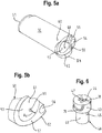
- Parallel to the cavity 53 extend in the axial direction L cavities 54, 55, 56, in particular also Fig. 5a to recognize.
- the cover element 50 has on the underside 52 a contact surface 57 which bears against an end face 111 of the handle 110 when the cover element 50 is connected to the connecting element 40.
- the cavities 54, 55, 56 which influence the deformability of the cover element 50, open at the contact surface 57 and thus at the same time influence the sliding friction between the contact surface 57 and the end face 111.
- the cavities 54, 55, 56 thus provide 57 points in the area of the contact surface a friction-reducing surface.
- the cover member 50 has a holder 58 which serves to hold a chip-shaped ball marker 59.
- a fastening element 30 which faces away from the connecting element 40 top 31 and the connecting element 40 facing away Bottom 32 has.
- the fastening element 30 is designed circular-cylindrical and has a peripheral surface 33.
- the connecting element 40 forms a clamping surface 48 which extends at a first angle ⁇ obliquely to the axial direction L.
- the fastener 30 forms at the top 31 a clamping surface 38 having a center Z and extending at a second angle ⁇ oblique to the axial direction L.
- the first angle ⁇ and the second angle ⁇ form minor angle, so complement each other to 180 °.
- the first angle ⁇ is about 150 ° and the second angle ⁇ is about 30 °.
- the clamping surfaces 48, 38 are therefore parallel. Depending on the application, however, the clamping surfaces 38, 48 may also include an angle.
- the fastener 30 extends from the top 31 to the nut 81 supporting contact surface 34, a slot 35 which receives the screw 80 with a play in the radial direction, ie in a direction perpendicular to the axial direction L, and outside the center Z of the clamping surface 38 is arranged.
- the contact surface 34 is formed by a shoulder 36 in a recess 37 on the bottom 32. The recess 37 receives the nut 81 secured against rotation.
- the resulting offset V causes the lateral surface 49 of the connecting element 40 and the circumferential surface 33 of the fastening element (30) to be pressed against the inner surface 113, resulting in a frictional connection between the fastening element 30 and the connecting element 40 on the one hand and the handle 110 on the other hand results.
- the fastening element 30 and the connecting element 40 are designed in one piece.
- the circumferential surface 33 of the fastening element 30 and the lateral surface 49 in the region of the lower part of the connecting element 40 form a fastening surface, which rests against the inner surface 113 and - for example, coated with an adhesive - a material connection between the fastening element 30 and the connecting element 40 on the one hand and the handle 110 causes on the other hand.
- the different embodiments of the device 10 differ in the design of the fastener 30 and the manner of attachment of the device 10 to the golf club 100.
- the embodiments have the embodiment of the cover member 50 and the releasable connection of the cover member 50 with the connecting member 40 by means of a bayonet catch.
- the connecting element 40 has two depressions 70, which are designed as a groove on regions of the lateral surface 43 facing away from one another.
- the cover element 50 has two projections or cams 60, which are formed on an inner surface 61 of the cavity 53 and, when the cover element 50 is plugged onto the connecting element 40, engage in the recesses 70.
- FIGS. 5a and 5b indicate the protrusions 60 are at a distance Av from the contact surface 57th
- the recesses 70 each follow a trajectory K, in particular Fig. 4b can be seen, extending from an opening at the top 41 beginning portion 71 to an end stop 73 ending at an end portion 72.
- the trajectory K In the transition region from the initial section 71 to the end section 72, the trajectory K has a local low point T, which is located at a distance A T from the end face 111 and in whose area the sign of the slope of the trajectory K changes.
- the trajectory K is decreasing and rises after reaching the low point T in the region of the end section 72.
- the slope of the trajectory K decreases in the end portion 72.
- the trajectory K is substantially parallel to the end face 111.
- the recesses 70 are therefore similar to a recumbent L.
- the cover member 50 completes the handle 110 and, therefore, is made of a material that meets the golfer's haptic and hardness requirements of a handle, such as rubber. Rubber is known to be an elastically deformable material. Accordingly, the cover element 50 can be compressed slightly when placed on the end face 111, whereby a restoring force in the axial direction L is generated. This is exploited when the cover member 50 is connected by means of a plug-and-turn movement with the connecting member 40, as shown in the FIGS. 7a to 8c can be seen.
- FIGS. 7a, 7b and 7c the cover element 50 is shown after being attached to the connecting element 40.
- the cover member 50 is rotated in this unlocked position by approximately 90 ° to the in the FIGS. 8a, 8b and 8c shown latched position in which the projection 60 abuts the end stop 73, in particular Fig. 7a to recognize.
- the projection 60 has penetrated a little way into the depression 70, which runs almost vertically at the beginning of the start section 71, as in particular Fig. 7c to recognize.
- the cover element 50 approaches by the rotational movement of the end face 111 of the handle 110.
- the contact surface 57 bears against the end face 111. A movement of the projection 60 beyond the low point T therefore requires a compression of the cover element 50.
- the size of the compression results from the difference between the distance A T and the distance that the straight running point of the trajectory K to the end face 111 has. Accordingly, the compression in the region of the low point T, which is located at a minimum distance A T to the end face 11, the largest, and decreases to the end stop 73, which is located at a distance A E to the end face 11 back out.
- the restoring force resulting from the compression of the cover element 50 in the axial direction L presses the projection 60 at the lower edge of the recess 70 in the axial direction L.
- the high point H which is located just before the end stop 73 and after reaching the trajectory K to the end stop 73 again slightly decreases, thus ensuring that the projection 60 form and frictionally held on the end stop 73, in particular Fig. 8c to recognize.
- the cover member 50 and the connecting member 40 are, when the projection 60 abuts the end stop 73, thereby reliably locked.
- the device 10 described above supplements the golf club 100 with a repair tool that is stowed away reliably by the cover element 50 when not in use.
- the bayonet catch resulting from the engagement of the projection 60 in the recess 70 and the formation of the recess 70 as a trajectory K extending along the lateral surface 43 makes it possible to releasably connect the cover element 50 to the connecting element 40 by means of an easily executed plug-and-turn movement. and easy to solve again by a reverse rotation.
- the bayonet lock in the locked position of the cover member 50 ensures a positive and non-positive grip of the projection 60 in the recess 70, which prevents unintentional release of the cover member 50 and thus does not affect the handling of the golf club 100.
Description
Die Erfindung betrifft eine Vorrichtung zum Ausbessern von Unebenheiten in einer auf einem Erdboden angeordneten Grünfläche. Die Vorrichtung ist geeignet, an einem Griff eines Golfschlägers befestigt zu werden.The invention relates to a device for repairing unevenness in a green area arranged on a ground. The device is adapted to be attached to a handle of a golf club.
Bei der Vorrichtung handelt es sich insbesondere um eine sogenannte Pitchgabel oder Divot Tool, einem beim Golfsport eingesetzten Hilfsmittel, um Vertiefungen oder Dellen, die durch aus vergleichsweise großer Höhe auf das sogenannte "Grün" eines Golfplatzes, einer auf einem Erdboden angeordneten Grünfläche, auftreffende Bälle entstanden sind, die sogenannten Pitchmarken, auszubessern. Diese Pitchmarken rühren daher, dass beim Golfen aus geringer Entfernung in Richtung Loch geschlagene Bälle häufig in einem hohen Bogen, dem sogenannten Pitch, gespielt werden, um zu vermeiden, dass der Ball über den kurzgeschorenen Rasen des "Grün" hinausrollt. Werden die Pitchmarken nicht repariert, dann wird die Fläche um das Loch herum uneben und das Einlochen eines Balles, das sogenannte Putten, bei späteren Runden erschwert. Um die Pitchmarken oder Unebenheiten auszubessern, wird mit einer in der Regel zwei-zinkigen Gabel rund um die Delle leicht schräg in den Rasen gestochen und der Kopf der Pitchgabel so zu der Delle gedrückt, dass die Grasnarbe gebrochen wird. Dies wird solange wiederholt, bis dort, wo die Delle war, eine pilzartige Auswölbung entsteht. Der Boden um die Pitchmark herum wird auf diese Weise gelockert und kann anschließend mit dem Putter wieder so eingeebnet werden, das kaum noch eine sichtbare Spur zurückbleibt.The device is, in particular, a so-called pitch fork or divot tool, a tool used in golf, around depressions or dents which strike balls from a comparatively great height on the so-called "green" of a golf course, a green area arranged on a ground have arisen, the so-called pitch marks, to mend. These pitch marks are due to the fact that when golfing from a short distance in the direction of hole beaten balls are often played in a high arc, the so-called pitch, to avoid that the ball rolls over the short-cut lawn of the "green". If the pitch marks are not repaired, the area around the hole will be uneven and the puttering of a ball, the so-called putting, will be difficult on later rounds. To repair the pitch marks or bumps, a generally two-pronged fork around the dent is pricked slightly obliquely into the lawn and the head of the pitch fork is pressed to the dent so that the turf is broken. This is repeated until there is a mushroom-like bulge where the dent was. The soil around the pitch mark is loosened in this way and can then be leveled with the putter again so that hardly leaves a visible trace.
Pitchgabeln gibt es in den unterschiedlichsten Ausführungsformen. Meist werden sie als separates Utensil während des Spiels von dem Golfer etwa in der Hosentasche mitgeführt.Pitchforks are available in various designs. Usually they are carried as a separate utensil during the game by the golfer in his pocket.
Bekannt ist allerdings auch, die Pitchgabel am Ende des Griffes eines Golfschlägers zu befestigen, um den Golfschläger als Stiel für die Pitchgabel benutzen zu können. Eine derartige Pitchgabel wird beispielsweise in
Eine an dem Griffende eines Golfschlägers befestigte Pitchgabel, die entlang einer Längsachse verschiebbar angeordnet ist, um von einer Gebrauchsstellung, in der die Zinken der Pitchgabel aus dem Griffende herausragen, in eine Verstaustellung, in der die Zinken der Pitchgabel im Inneren des Griffes zum Liegen kommen, gebracht zu werden, beschreibt
Ein am Ende des Griffes eines Golfschlägers befestigtes Reparaturwerkzeug, das durch eine kraftschlüssig aufgesteckte Abdeckkappe bei Nichtgebrauch abgedeckt ist, wird ferner in
Eine mit einem Schraubgewinde versehene Pitchgabel, die sich in das Griffende eines Golfschlägers einschrauben lässt, offenbart
Eine am Ende des Griffes eines Golfschlägers befestigte Pitchgabel, die mittels eines durch eine Schraub-Spreiz-Verbindung erzeugten Reibschlusses befestigt wird, offenbart
Der Erfindung liegt die Aufgabe zugrunde, eine Vorrichtung zum Ausbessern von Unebenheiten in einer auf einem Erdboden befindlichen Grünfläche, insbesondere dem Grün eines Golfplatzes, zu schaffen, die sich an dem Griff eines Golfschlägers befestigen lässt und durch welche die Handhabung des Golfschlägers nicht beeinträchtigt wird.The invention has for its object to provide a device for repairing bumps in a located on a ground green area, especially the green of a golf course, which can be attached to the handle of a golf club and by which the handling of the golf club is not affected.
Diese Aufgabe wird durch eine Vorrichtung nach Anspruch 1 oder Anspruch 2 sowie einen Golfschläger nach Anspruch 12 gelöst. Vorteilhafte Ausgestaltungen der Vorrichtung und des Golfschlägers sind Gegenstand der Ansprüche 3 bis 11 und 13 bis 15.This object is achieved by a device according to claim 1 or claim 2 and a golf club according to claim 12. Advantageous embodiments of the device and the golf club are the subject matter of claims 3 to 11 and 13 to 15.
Die erfindungsgemäße Vorrichtung zum Ausbessern von Unebenheiten in einer auf einem Erdboden angeordneten Grünfläche umfasst ein Befestigungselement, mittels dem die Vorrichtung an dem Griff eines Golfschlägers befestigt werden kann, und ein Einführelement, das geeignet ist, zum Ausbessern von Unebenheiten in den Erdboden eingeführt zu werden. Bei dem Einführelement handelt es sich insbesondere um eine Pitchgabel. Die Vorrichtung umfasst ferner ein Abdeckungselement oder Kappe zum Abdecken des Einführelements. Durch das Abdeckungselement wird der Benutzer des Golfschlägers vor Verletzungen geschützt, die durch das Einführelement verursacht werden können.The device according to the invention for repairing unevenness in a green area arranged on a ground comprises a fastening element, by means of which the device can be fastened to the handle of a golf club, and an insertion element which is suitable for being introduced into the ground for repairing unevenness. The insertion element is in particular a pitch fork. The device further comprises a cover element or cap for covering the insertion element. By the cover member of the user of the golf club is protected from injury that may be caused by the insertion.
Darüber hinaus umfasst die Vorrichtung ein Verbindungselement, das sich mittels eines Bajonettverschlusses lösbar mit dem Abdeckungselement verbinden lässt. Die Verbindung von Abdeckungselement und Verbindungselement erfolgt demnach über eine Steck-Dreh-Bewegung. Zum Bilden des Bajonettverschlusses weist das Verbindungselement wenigstens eine Vertiefung auf, die einen Anfangsabschnitt und einen Endabschnitt hat. Das Abdeckungselement weist wenigstens einen Vorsprung auf, der in die Vertiefung eingreift und zum Verbinden von Abdeckungselement und Verbindungselement von dem Anfangsabschnitt in den Endabschnitt bewegt werden kann. Zum Lösen des Abdeckungselements von dem Verbindungselement wird der Vorsprung von dem Endabschnitt zurück in den Anfangsabschnitt bewegt. Alternativ oder zusätzlich können wenigstens eine Vertiefung an dem Abdeckungselement und wenigstens ein in die Vertiefung eingreifender Vorsprung an dem Verbindungselement ausgebildet sein.In addition, the device comprises a connecting element which can be detachably connected to the cover element by means of a bayonet closure. The connection of the cover element and connecting element is accordingly via a plug-in rotary movement. To form the bayonet closure, the connecting element has at least one recess, which has a beginning portion and an end portion. The cover member has at least one protrusion which engages the recess and can be moved to connect the cover member and connecting member from the starting portion to the end portion. For releasing the cover member from the Connecting element, the projection is moved from the end portion back into the initial section. Alternatively or additionally, at least one depression on the cover element and at least one projection engaging in the depression can be formed on the connection element.
Befindet sich der Vorsprung in dem Anfangsabschnitt, dann lässt sich das Abdeckungselement von dem Verbindungselement trennen und das Abdeckungselement damit von dem Einführelement entfernen. In dem Endabschnitt hingegen wird der Vorsprung form- und kraftschlüssig in der Vertiefung gehalten. Das Abdeckungselement ist auf diese Weise zuverlässig mit dem Verbindungselement verbunden, und zwar derart sicher, dass die Handhabung des Golfschlägers nicht beeinträchtigt wird. Weder löst sich das Abdeckungselement versehentlich beim Gebrauch des Golfschlägers noch wird der sogenannte Griffdruck, der für das Halten des Golfschlägers wichtig ist, durch das Abdeckungselement beeinflusst.If the projection is in the starting section, then the cover element can be separated from the connecting element and thus the cover element can be removed from the insertion element. In the end section, however, the projection is held positively and non-positively in the recess. The cover member is thus reliably connected to the connecting member, and so sure that the handling of the golf club is not affected. Neither does the cover element accidentally disengage when the golf club is in use, nor is the so-called grip pressure, which is important for holding the golf club, affected by the cover element.
In einer bevorzugten Ausgestaltung der erfindungsgemäßen Vorrichtung hat das Verbindungselement eine Oberseite, eine Unterseite und eine Mantelfläche, die vorzugsweise zylindrisch, insbesondere kreiszylindrisch, ist. Das Verbindungselement setzt sich vorzugsweise aus einem oberen Teil und einem unteren Teil, der einen geringeren Durchmesser als der obere Teil hat, zusammen. Die Vertiefung ist als Nut ausgestaltet, die einer Bahnkurve folgend sich entlang der Mantelfläche erstreckt. Alternativ oder zusätzlich kann sich die Bahnkurve oder eine weitere Bahnkurve entlang einer vorzugsweise zylindrischen, insbesondere kreiszylindrischen, Innenfläche des Abdeckungselements erstrecken, und zwar insbesondere dann, wenn der Vorsprung alternativ oder zusätzlich an dem Verbindungselement ausgebildet ist.In a preferred embodiment of the device according to the invention, the connecting element has an upper side, a lower side and a lateral surface, which is preferably cylindrical, in particular circular-cylindrical. The connecting element is preferably composed of an upper part and a lower part which has a smaller diameter than the upper part together. The recess is configured as a groove which extends along a trajectory along the lateral surface. Alternatively or additionally, the trajectory or a further trajectory may extend along a preferably cylindrical, in particular circular cylindrical, inner surface of the cover element, in particular when the projection is formed alternatively or additionally on the connecting element.
Erfindungsgemäß hat die Bahnkurve im Übergangsbereich von dem Anfangsabschnitt zu dem Endabschnitt einen zumindest lokalen Tiefpunkt. Vorzugsweise ist zumindest im Bereich des Tiefpunktes das Vorzeichen der Steigung der Bahnkurve in dem Anfangsabschnitt umgekehrt zu dem Vorzeichen der Steigung in dem Endabschnitt. Erfindungsgemäß ist der Vorsprung entgegen der Wirkung einer in einer axialen Richtung wirkenden Rückstellkraft von dem Anfangsabschnitt zu dem Endabschnitt bewegbar. Wird der Vorsprung in dem Anfangsabschnitt entlang einer fallenden Bahnkurve bewegt, dann ist das Vorzeichen der Steigung der Bahnkurve beispielsweise negativ. Nach dem Erreichen des Tiefpunktes wechselt das Vorzeichen der Steigung der Bahnkurve und ist positiv. Der Vorsprung wird demnach in dem Endabschnitt entlang einer steigenden Bahnkurve bewegt. Insbesondere dann, wenn die Bewegung des Vorsprungs zum Tiefpunkt entgegen der Wirkung einer axialen Rückstellkraft, beispielsweise einer Federkraft, erfolgt, verhindert die steigende Bahnkurve, dass sich der Vorsprung selbsttätig zurückbewegt. Wird das Abdeckungselement demnach so weit gedreht, dass der Tiefpunkt überschritten wird, dann werden das Abdeckungselement und das Verbindungselement gegeneinander verspannt.According to the invention, the trajectory in the transition region from the initial section to the end section has an at least local low point. Preferably, at least in the region of the low point, the sign of the slope of the trajectory in the initial section is inverse to the sign of the gradient in the end section. According to the invention, the projection is movable against the action of a restoring force acting in an axial direction from the initial portion to the end portion. If the projection in the initial section is moved along a falling trajectory, then the sign of the slope is Trajectory, for example, negative. After reaching the low point, the sign changes the slope of the trajectory and is positive. The projection is thus moved in the end portion along a rising trajectory. In particular, when the movement of the projection to the bottom against the action of an axial restoring force, such as a spring force, takes place, prevents the rising trajectory that the projection moves back automatically. If the cover element is therefore rotated so far that the low point is exceeded, then the cover element and the connecting element are braced against each other.
Zweckmäßigerweise wird der Endabschnitt durch einen Endanschlag für den Vorsprung begrenzt. Vorzugsweise nimmt die Steigung der Bahnkurve in dem Endabschnitt zu dem Endanschlag hin ab. Vorzugsweise befindet sich kurz vor dem Endanschlag ein lokaler Hochpunkt, das heißt die Bahnkurve fällt zum Endanschlag hin wieder leicht ab. Insbesondere dann, wenn die Bewegung des Vorsprungs zum Tiefpunkt entgegen der Wirkung einer axialen Rückstellkraft erfolgt, lässt sich durch die Steigung der Bahnkurve gezielt die Kraft vorgeben, mit welcher das Abdeckungselement und das Verbindungselement bei Erreichen des Endanschlags gegeneinander verspannt sein müssen, um einerseits einen festen Sitz und andererseits ein bequemes Lösen des Abdeckungselements zu gewährleisten. Durch den Endanschlag erhält der Benutzer zudem eine Rückmeldung, wenn das Abdeckungselement sicher mit dem Verbindungselement verbunden ist. Erfindungsgemäß hat das Abdeckungselement eine Oberseite und eine Unterseite und weist wenigstens einen an der Unterseite mündenden Hohlraum auf. Der Hohlraum ist geeignet, das Einführelement und das Verbindungselement aufzunehmen. Weitere Hohlräume können beispielsweise dazu dienen, dem Abdeckungselement eine bestimmte Verformungsfähigkeit oder Härte zu verleihen. Härtere Griffe bieten eine gute Kontrolle und ermutigen den Spieler oft dazu, den Schläger mit weniger Druck in der Hand zu halten. Weichere Griffe hingegen lassen sich in der Regel bequemer anfassen.Conveniently, the end portion is limited by an end stop for the projection. Preferably, the slope of the trajectory in the end portion decreases toward the end stop. Preferably, there is a local high point just before the end stop, that is, the trajectory falls slightly towards the end stop again. In particular, when the movement of the projection to the bottom occurs against the action of an axial restoring force, can be specified by the slope of the trajectory specifically the force with which the cover element and the connecting element must be braced against each other when reaching the end stop, on the one hand a solid Seat and on the other hand to ensure a comfortable release of the cover element. The end stop also provides feedback to the user when the cover member is securely connected to the connector. According to the invention, the cover element has an upper side and a lower side and has at least one cavity opening out on the underside. The cavity is adapted to receive the insertion element and the connecting element. Other cavities may serve, for example, to give the cover member a certain deformability or hardness. Tougher grips provide good control and often encourage the player to hold the bat with less pressure. Softer handles, on the other hand, are generally easier to handle.
Von besonderem Vorteil ist es, wenn das Abdeckungselement zumindest bereichsweise, insbesondere im Bereich des Vorsprungs oder der Vertiefung, aus einem elastisch verformbaren Werkstoff gefertigt ist. Ein geeigneter Werkstoff ist beispielsweise Gummi. Gummi ist als Material leicht zu formen und zu produzieren und bietet ein festes, haftendes Gefühl. Andere geeignete Werkstoff können beilspielsweise Silikon, Elastomere oder sonstige elastisch verformbare Kunststoffe oder Mischungen aus den vorgenannten Materialien sein.It is particularly advantageous if the cover element is made of an elastically deformable material at least regionally, in particular in the region of the projection or the depression. A suitable material is for example rubber. Rubber is easy to shape and produce as a material and provides a firm, sticky feel. Other suitable material may be, for example, silicone, elastomers or other elastically deformable plastics or mixtures of the aforementioned materials.
In einer bevorzugten Ausgestaltung der erfindungsgemäßen Vorrichtung weist das Abdeckungselement an der Unterseite eine Kontaktfläche auf, die geeignet ist, an einer Stirnfläche des Griffes oder eines Teil des Griffes eines Golfschlägers anzuliegen. Wird beispielsweise ein vorhandener Golfschläger mit der erfindungsgemäßen Vorrichtung nachgerüstet, ist es möglich, einen Teil des Griffes abzuschneiden und diesen durch ein Abdeckungselement zu ersetzen, das in Haptik und Griffstärke dem abgetrennten Teil entspricht. Die Schnittfläche bildet in diesem Fall die Stirnfläche.In a preferred embodiment of the device according to the invention, the cover element on the underside on a contact surface which is adapted to abut against an end face of the handle or a part of the handle of a golf club. If, for example, an existing golf club is retrofitted with the device according to the invention, it is possible to cut off a part of the handle and replace it with a cover element which corresponds in feel and grip to the severed part. The cut surface forms the end face in this case.
Vorzugsweise weist die Kontaktfläche zumindest abschnittsweise Stellen mit einer reibungsvermindernden Oberfläche auf. Diese Stellen können beispielsweise durch die Hohlräume gebildet werden und dienen dazu, die Gleitreibung zwischen Stirnfläche und Kontaktfläche zu beeinflussen.Preferably, the contact surface at least partially points with a friction-reducing surface. These locations can be formed for example by the cavities and serve to influence the sliding friction between the end face and contact surface.
Wenn das Abdeckungselement insbesondere im Bereich des Vorsprungs oder der Vertiefung elastisch verformbar ist, dann ist es möglich, den Abstand zwischen der Kontaktfläche des Abdeckungselementes und der Stirnfläche des Griffes so vorzugeben, dass das Abdeckungselement bei dem Aufstecken auf das Verbindungselement etwas gestaucht werden muss, um den Vorsprung in den Endabschnitt zu bewegen. Durch die elastische Verformung, die mit der Stauchung einhergeht, entsteht eine in axialer Richtung wirkende Rückstellkraft, die im Tiefpunkt am größten ist und im Endabschnitt das Abdeckungselement und das Verbindungselement zuverlässig gegeneinander verspannt.If the cover element is elastically deformable, in particular in the region of the projection or of the recess, then it is possible to specify the distance between the contact surface of the cover element and the end face of the handle in such a way that the cover element must be slightly compressed when it is slipped onto the connecting element to move the projection into the end section. Due to the elastic deformation associated with the compression creates a restoring force acting in the axial direction, which is greatest in the low point and reliably clamped in the end portion of the cover member and the connecting element against each other.
Zweckmäßigerweise weist das Abdeckungselement an der Oberseite eine Halterung auf, die geeignet ist, einen insbesondere chipförmigen Ballmarker zu halten. Mit dem Ballmarker wird auf dem Grün die Position eines Golfballs markiert, um diesen danach aufnehmen zu können. Als Ballmarker finden häufig Münzen oder auch dafür vorgesehene Druckknöpfe an Golfhandschuhen Verwendung. Zunehmend beliebter und häufig als Werbegeschenk verwendet sind chipförmige Ballmarker, die sich individuell gestalten oder bedrucken lassen.Conveniently, the cover member on the top of a holder which is adapted to hold a particular chip-shaped ball marker. With the ball marker the position of a golf ball is marked on the green in order to be able to record it afterwards. As a ballmarker coins or even designated snaps are often used on golf gloves use. Increasingly popular and often used as a giveaway are chip-shaped ball markers that can be personalized or printed.
Das Einführelement weist bevorzugt einen Halteabschnitt, der vorzugsweise eben ausgestaltet ist, und von dem Halteabschnitt abstehende Zinken, die vorzugsweise gewölbt ausgestaltet sind, auf. Das Einführelement ist damit ein Ausbesserungswerkzeug, eine sogenannte Pitchgabel, dessen Zinken um die Pitchmarke herum in den Rasen gestochen und in geeigneter Weise bewegt werden, um die Verformung der Grasnarbe rückgängig zu machen. Die Wölbung der Zinken trägt zu einem schonenden Einstechen der Zinken in den Rasen bei, so dass eine anhaltende Schädigung der Grasnarbe vermieden wird.The insertion element preferably has a holding portion, which is preferably configured flat, and protruding from the holding portion prongs, which are preferably curved, on. The insertion element is thus a repair tool, a so-called pitch fork, the tines are pricked around the pitch mark in the lawn and moved in a suitable manner to reverse the deformation of the turf. The curvature of the tines bears to gently prick the tines into the grass, thus avoiding prolonged damage to the turf.
Um das Einführelement an dem Verbindungselement zu befestigen, weist das Verbindungselement an der Oberseite eine erste Öffnung auf, in welcher der Halteabschnitt angeordnet ist. Vorzugsweise weist das Verbindungselement an der Mantelfläche eine zweite Öffnung auf, in der eine den Halteabschnitt fixierende Sicherungsschraube aufgenommen ist. Zur Montage des Einführelements wird demnach der Halteabschnitt in die erste Öffnung gesteckt und anschließend die beispielsweise als Madenschraube ausgestaltete Sicherungsschraube in der zweiten, mit einem Gewinde versehenen Öffnung angezogen.In order to fix the insertion element to the connecting element, the connecting element has on the upper side a first opening in which the holding section is arranged. Preferably, the connecting element on the lateral surface on a second opening, in which a retaining portion fixing locking screw is received. For mounting the insertion element, therefore, the holding section is inserted into the first opening and then tightened, for example, designed as a set screw locking screw in the second, threaded opening.
In einer bevorzugten Ausgestaltung der erfindungsgemäßen Vorrichtung sind das Befestigungselement und das Verbindungselement durch eine Schraubverbindung miteinander verbunden. Vorzugsweise ist das Verbindungselement zur Aufnahme einer sich vorzugsweise in der axialen Richtung erstreckenden Schraube mit einer sich von der Oberseite bis zur Unterseite erstreckenden Durchgangsöffnung versehen. Zweckmäßigerweise hat das Befestigungselement eine Oberseite und eine Unterseite und ist zum Abstützen einer mit der Schraube zusammenwirkenden Mutter mit einer insbesondere an der Unterseite ausgebildeten Anlagefläche versehen.In a preferred embodiment of the device according to the invention, the fastening element and the connecting element are connected to one another by a screw connection. Preferably, the connecting element for receiving a preferably extending in the axial direction screw is provided with a extending from the top to the bottom through hole. Conveniently, the fastener has a top and a bottom and is provided for supporting a cooperating with the screw nut with a particular formed on the bottom contact surface.
In diesem Zusammenhang ist es besonders vorteilhaft, wenn das Verbindungselement an der Unterseite eine Klemmfläche aufweist, die sich unter einem ersten Winkel schräg zu der axialen Richtung erstreckt, und das Befestigungselement an der Oberseite eine Klemmfläche aufweist, die ein Zentrum hat und sich unter einem zweiten Winkel schräg zu der axialen Richtung erstreckt. Der erste Winkel und der zweite Winkel bilden vorzugsweise Nebenwinkel, ergänzen sich also zu 180°. Die Klemmflächen verlaufen in diesem Fall parallel. Vorzugsweise betragen der erste Winkel zwischen 130° und 170°, insbesondere zwischen 140° und 160°, beispielsweise ca. 150°, und der zweite Winkel zwischen 10° und 50°, insbesondere zwischen 20° und 40°, beispielsweise ca. 30°.In this context, it is particularly advantageous if the connecting element on the underside has a clamping surface which extends at a first angle obliquely to the axial direction, and the fastening element at the top has a clamping surface which has a center and under a second Angle extends obliquely to the axial direction. The first angle and the second angle preferably form secondary angles, thus complement each other to 180 °. The clamping surfaces are parallel in this case. Preferably, the first angle between 130 ° and 170 °, in particular between 140 ° and 160 °, for example, about 150 °, and the second angle between 10 ° and 50 °, in particular between 20 ° and 40 °, for example, about 30 ° ,
Bevorzugt weist das Befestigungselement ein sich von der Oberseite bis zu der Anlagefläche für die Mutter in der axialen Richtung erstreckendes Langloch auf, das die Schraube mit radialem Spiel aufnimmt und außerhalb des Zentrums der Klemmfläche angeordnet ist. Durch das Anziehen der Schraube werden das Verbindungselement und das Befestigungselement an den Klemmflächen gegeneinander verspannt. Die außermittige Anordnung des Langloches und das radiale Spiel bewirken, dass das Verbindungselement und das Befestigungselement beim Anziehen der Schraube ein Stück weit entlang der Klemmflächen auseinandergleiten bis die Schraube in radialer Richtung an den Rand des Langloches anschlägt. Der sich mit dem Auseinandergleiten in radialer Richtung ergebende Versatz von Verbindungselement und Befestigungselement ermöglicht es, die erfindungsgemäße Vorrichtung kraftschlüssig an insbesondere dem Griff eines Golfschlägers zu befestigen.Preferably, the fastening element has a slot extending from the upper side to the contact surface for the nut in the axial direction, which receives the screw with radial clearance and is located outside the center of the clamping surface. By tightening the screw, the connecting element and the fastening element are braced against each other at the clamping surfaces. The eccentric arrangement of the elongated hole and the radial clearance cause the connecting element and the fastening element when tightening the screw a little way along the clamping surfaces slide apart until the screw abuts in the radial direction to the edge of the elongated hole. The resulting with the sliding apart in the radial direction offset of the connecting element and fastener makes it possible to force fit the device according to the invention in particular the handle of a golf club.
In einer weiteren bevorzugten Ausgestaltung der erfindungsgemäßen Vorrichtung sind das Befestigungselement und das Verbindungselement zwar ebenfalls durch eine Schraubverbindung miteinander verbunden, das Befestigungselement umfasst aber wenigstens ein aus einem verformbaren Werkstoff bestehendes Klemmelement und wenigstens ein das Klemmelement beaufschlagendes Druckelement. Das Klemmelement und das Druckelement sind vorzugsweise mittels der Schraubverbindung gegeneinander verspannt. Beim Verspannen wird das Klemmelement verformt. Eine auf diese Weise entstehende Ausbauchung des Klemmelementes ermöglicht es, die erfindungsgemäße Vorrichtung kraftschlüssig an insbesondere dem Griff eines Golfschlägers zu befestigen. Das vergleichsweise starke Ausbauchen des Klemmelementes ermöglicht zudem, Fertigungstoleranzen auszugleichen.Although in a further preferred embodiment of the device according to the invention the fastening element and the connecting element are likewise connected to one another by a screw connection, the fastening element comprises at least one clamping element consisting of a deformable material and at least one pressure element acting on the clamping element. The clamping element and the pressure element are preferably braced against each other by means of the screw connection. When tightening the clamping element is deformed. A resulting bulging of the clamping element makes it possible to force-fit the device according to the invention to, in particular, the grip of a golf club. The comparatively strong bulging of the clamping element also makes it possible to compensate for manufacturing tolerances.
In einer anderen bevorzugten Ausgestaltung der erfindungsgemäßen Vorrichtung sind das Befestigungselement und das Verbindungselement einteilig ausgestaltet. Das Befestigungselement weist vorzugsweise eine Umfangsfläche auf, die geeignet ist, stoffschlüssig an einer Innenfläche des Griffes befestigt zu werden.In another preferred embodiment of the device according to the invention, the fastening element and the connecting element are designed in one piece. The fastening element preferably has a peripheral surface which is suitable to be fastened to an inner surface of the handle in a material-locking manner.
Der erfindungsgemäße Golfschläger, der insbesondere als Putter ausgestaltet ist, umfasst einen Schaft, einen Griff, der an einem Ende des Schafts angeordnet ist, und einen Kopf, der an dem anderen Ende des Schaftes angeordnet ist. Der Golfschläger zeichnet sich dadurch aus, dass die erfindungsgemäße Vorrichtung an dem Griff befestigt ist.The golf club according to the invention, which is designed in particular as a putter, comprises a shaft, a handle which is arranged at one end of the shaft, and a head which is arranged at the other end of the shaft. The golf club is characterized in that the device according to the invention is attached to the handle.
In einer bevorzugten Ausgestaltung des erfindungsgemäßen Golfschlägers weist der Griff einen insbesondere rohrförmigen Hohlraum auf, der eine Innenfläche hat und in dem das Befestigungselement und/oder das Verbindungselement, insbesondere der untere Teil des Verbindungselementes, angeordnet sind. Der Hohlraum kann beispielsweise durch den Schaft gebildet werden.In a preferred embodiment of the golf club according to the invention, the handle has a particular tubular cavity, which has an inner surface and in which the fastening element and / or the connecting element, in particular the lower part of the connecting element, are arranged. The cavity can be formed, for example, by the shaft.
Das Befestigungselement ist bevorzugt mittels Kraftschluss mit dem Griff verbunden. Diese Ausgestaltung bietet sich an, wenn die erfindungsgemäße Vorrichtung bei herkömmlichen Golfschlägern nachgerüstet wird. Vorzugsweise liegt die Umfangsfläche des Befestigungselementes oder das Klemmelement kraftschlüssig an der Innenfläche des Griffes an. Der Versatz von Verbindungselement und Befestigungselement oder das Ausbauchen des Klemmelements rufen einen wirksamen Kraftschluss hervor, der gewährleistet, dass die erfindungsgemäße Vorrichtung sicher und dauerhaft mit dem Griff des Golfschlägers verbunden bleibt.The fastening element is preferably connected by means of frictional connection with the handle. This embodiment lends itself when the device according to the invention is retrofitted to conventional golf clubs. Preferably, the peripheral surface of the fastening element or the clamping element is frictionally against the inner surface of the handle. The offset of the connecting element and fastening element or the bulging of the clamping element cause an effective frictional connection, which ensures that the device according to the invention remains securely and permanently connected to the grip of the golf club.
Das Befestigungselement kann jedoch alternativ oder zusätzlich mittels Stoffschluss mit dem Griff verbunden sein. In diesem Fall liegt vorzugsweise die Umfangsfläche des Befestigungselementes, auf die ein Klebstoff aufgetragen werden kann, stoffschlüssig an der Innenfläche des Griffes an.However, the fastener may alternatively or additionally be connected by means of material connection with the handle. In this case, preferably the peripheral surface of the fastening element, to which an adhesive can be applied, is firmly bonded to the inner surface of the handle.
Einzelheiten und weitere Vorteile der Erfindung ergeben sich aus der nachfolgenden Beschreibung von bevorzugten Ausführungsbeispielen. In den die Ausführungsbeispiele lediglich schematisch veranschaulichenden Zeichnungen zeigen im Einzelnen:
- Fig. 1a
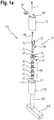
- eine Explosionsdarstellung eines Golfschlägers, die eine erste Ausführungsform der erfindungsgemäßen Vorrichtung zeigt;
- Fig. 1b
- einen Längsschnitt durch die erste Ausführungsform;
- Fig. 2a
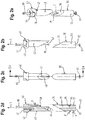
- eine perspektivische Ansicht von Verbindungselement und Befestigungselement gemäß einer zweiten Ausführungsform der erfindungsgemäßen Vorrichtung;
- Fig. 2b
- eine Seitenansicht von Verbindungselement und Befestigungselement gemäß der zweiten Ausführungsform;
- Fig. 2c
- eine weitere Seitenansicht gemäß
Fig. 2b ; - Fig. 2d
- einen Schnitt entlang der Linie IId-IId in
Fig. 2c ; - Fig. 3
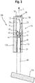
- einen Längsschnitt durch eine dritte Ausführungsform der erfindungsgemäßen Vorrichtung;
- Fig. 4a
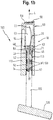
- eine perspektivische Ansicht des erfindungsgemäßen Golfschlägers bei abgenommenem Abdeckungselement;
- Fig. 4b
- eine vergrößerte Darstellung des in
Fig. 4a mit IVb gekennzeichneten Bereichs; - Fig. 5a
- eine perspektivische Ansicht eines Abdeckungselementes;
- Fig. 5b
- eine vergrößerte Darstellung des in
Fig. 5a mit Vb gekennzeichneten Bereichs; - Fig. 6
- eine perspektivische Ansicht eines Verbindungselementes;
- Fig. 7a
- eine Draufsicht auf den erfindungsgemäßen Golfschläger, die das Abdeckungselement in einer entriegelten Stellung zeigt;
- Fig. 7b
- einen Schnitt entlang der Linie VIIb-VIIb in
Fig. 7a ; - Fig. 7c
- eine vergrößerte Darstellung des in
Fig. 7b mit VIIc gekennzeichneten Bereichs; - Fig. 8a
- eine Draufsicht auf den erfindungsgemäßen Golfschläger, die das Abdeckungselement in einer verriegelten Stellung zeigt;
- Fig. 8b
- einen Schnitt entlang der Linie VIIIb-VIIIb in
Fig. 8a und - Fig. 8c
- eine vergrößerte Darstellung des in
Fig. 8b mit VIIIc gekennzeichneten Bereichs.
- Fig. 1a
- an exploded view of a golf club, showing a first embodiment of the device according to the invention;
- Fig. 1b
- a longitudinal section through the first embodiment;
- Fig. 2a
- a perspective view of the connecting element and fastener according to a second embodiment of the device according to the invention;
- Fig. 2b
- a side view of the connecting element and fastening element according to the second embodiment;
- Fig. 2c
- another side view according
Fig. 2b ; - Fig. 2d
- a section along the line IId-IId in
Fig. 2c ; - Fig. 3
- a longitudinal section through a third embodiment of the device according to the invention;
- Fig. 4a
- a perspective view of the golf club according to the invention with removed cover member;
- Fig. 4b
- an enlarged view of the in
Fig. 4a area marked IVb; - Fig. 5a
- a perspective view of a cover member;
- Fig. 5b
- an enlarged view of the in
Fig. 5a area labeled Vb; - Fig. 6
- a perspective view of a connecting element;
- Fig. 7a
- a plan view of the golf club according to the invention, showing the cover member in an unlocked position;
- Fig. 7b
- a section along the line VIIb-VIIb in
Fig. 7a ; - Fig. 7c
- an enlarged view of the in
Fig. 7b area indicated by VIIc; - Fig. 8a
- a plan view of the golf club according to the invention, showing the cover member in a locked position;
- Fig. 8b
- a section along the line VIIIb-VIIIb in
Fig. 8a and - Fig. 8c
- an enlarged view of the in
Fig. 8b Area marked VIIIc.
Der in den
Die Vorrichtung 10 umfasst ein als Pitchgabel ausgestaltetes Einführelement 20, ein das Einführelement 20 abdeckendes Abdeckungselement 50, ein Verbindungselement 40 und ein Befestigungselement 30, 90.The
Das Einführelement 20 weist einen eben ausgestalteten Halteabschnitt 21 und von dem Haltabschnitt 21 abstehende Zinken 22 auf. Die Zinken 22 sind gewölbt ausgestaltet. Das Verbindungselement 40 hat eine dem Befestigungselement 30, 90 abgewandte Oberseite 41 und eine dem Befestigungselement 30, 90 zugewandte Unterseite 42 und setzt sich, wie insbesondere auch
Das Befestigungselement 90 und das Verbindungselement 40 sind in einer ersten Ausführungsform der Vorrichtung 10 durch eine Schraubverbindung, die eine Schraube 80 und eine Mutter 81 umfasst, miteinander verbunden. Zur Aufnahme der sich in einer axialen Richtung L erstreckenden Schraube 80 ist das Verbindungselement 40 mit einer sich von der Oberseite 41 bis zur Unterseite 42 erstreckenden Durchgangsöffnung 47 versehen.The
Das Befestigungselement 90 setzt sich bei der in den
Das Abdeckungselement 50 hat eine dem Griff 110 abgewandte Oberseite 51 und eine dem Griff 110 zugewandte Unterseite 52. Ein an der Unterseite 52 mündender Hohlraum 53 nimmt das Einführelement 20 und den oberen Teil des Verbindungselements 40 auf. Der untere Teil des Verbindungselements 40 hingegen kommt in dem Hohlraum 112 zu liegen. Parallel zu dem Hohlraum 53 erstrecken sich in axialer Richtung L Hohlräume 54, 55, 56, wie insbesondere auch
Wie die
Durch das Anziehen der Schraube 80 werden das Verbindungselement 40 und das Befestigungselement 30 an den Klemmflächen 38, 48 gegeneinander verspannt. Die außermittige Anordnung des Langlochs 35 und das radiale Spiel der Schraube 80 bewirken, dass das Verbindungselement 40 und das Befestigungselement 30 beim Anziehen der Schraube 80 ein Stück weit entlang der Klemmflächen 38, 48 auseinandergleiten, und zwar so weit, bis die Schraube 80 in radialer Richtung an den Rand des Langlochs 35 anschlägt. Auf diese Weise ergibt sich in radialer Richtung ein Versatz V von Verbindungselement 40 und Befestigungselement 30, wie insbesondere in
Wie
Die unterschiedlichen Ausführungsformen der Vorrichtung 10 unterscheiden sich in der Ausgestaltung des Befestigungselements 30 und der Art der Befestigung der Vorrichtung 10 an dem Golfschläger 100. Gemein haben die Ausführungsformen jedoch die Ausgestaltung des Abdeckungselements 50 und die lösbare Verbindung des Abdeckungselements 50 mit dem Verbindungselement 40 mittels eines Bajonettverschlusses. Wie insbesondere die
Die Vertiefungen 70 folgen jeweils einer Bahnkurve K, die, wie insbesondere
Das Abdeckungselement 50 vervollständigt den Griff 110 und besteht daher aus einem Werkstoff, der die Anforderungen eines Golfers an Haptik und Härte eines Griffs erfüllt, wie beispielsweise Gummi. Gummi ist bekanntlich ein elastisch verformbarer Werkstoff. Das Abdeckungselement 50 lässt sich demnach beim Aufsetzen auf die Stirnfläche 111 ein Stück weit stauchen, wodurch eine Rückstellkraft in axialer Richtung L erzeugt wird. Dies wird ausgenutzt, wenn das Abdeckungselement 50 mittels einer Steck-Dreh-Bewegung mit dem Verbindungselement 40 verbunden wird, wie anschaulich in den
In den
Die Größe der Stauchung ergibt sich aus der Differenz zwischen dem Abstand AT und dem Abstand, den der gerade durchlaufende Punkt der Bahnkurve K zu der Stirnfläche 111 hat. Demnach ist die Stauchung im Bereich des Tiefpunkts T, der sich in einem minimalen Abstand AT zu der Stirnfläche 11 befindet, am größten und nimmt zu dem Endanschlag 73, der sich in einem Abstand AE zu der Stirnfläche 11 befindet, hin wieder ab. Die sich durch die Stauchung des Abdeckungselementes 50 in axialer Richtung L ergebende Rückstellkraft presst den Vorsprung 60 an den in axialer Richtung L unteren Rand der Vertiefung 70. Der Hochpunkt H, der sich kurz vor dem Endanschlag 73 befindet und nach dessen Erreichen die Bahnkurve K zu dem Endanschlag 73 hin wieder leicht abfällt, gewährleistet damit, dass der Vorsprung 60 form- und kraftschlüssig an dem Endanschlag 73 gehalten wird, wie insbesondere
Die zuvor beschriebene Vorrichtung 10 ergänzt den Golfschläger 100 um ein Ausbesserungswerkzeug, das bei Nichtgebrauch durch das Abdeckungselement 50 zuverlässig verstaut ist. Der durch das Eingreifen des Vorsprungs 60 in die Vertiefung 70 und die Ausbildung der Vertiefung 70 als sich entlang der Mantelfläche 43 erstreckende Bahnkurve K ergebende Bajonettverschluss ermöglicht mittels einer einfach auszuführenden Steck-Dreh-Bewegung, das Abdeckungselement 50 lösbar mit dem Verbindungselement 40 zu verbinden, und durch eine umgekehrte Drehbewegung wieder einfach zu lösen. Zugleich gewährleistet der Bajonettverschluss in der verriegelten Position des Abdeckungselements 50 einen form- und kraftschlüssigen Halt des Vorsprungs 60 in der Vertiefung 70, der ein unbeabsichtigtes Lösen des Abdeckungselements 50 verhindert und damit die Handhabung der Golfschlägers 100 nicht beeinträchtigt.The
- 1010
- Vorrichtungcontraption
- 2020
- Einführelementinsertion
- 2121
- Halteabschnittholding section
- 2222
- Zinkenprong
- 3030
- Befestigungselementfastener
- 3131
- Oberseitetop
- 3232
- Unterseitebottom
- 3333
- Umfangsflächeperipheral surface
- 3434
- Anlageflächecontact surface
- 3535
- LanglochLong hole
- 3636
- Absatzparagraph
- 3737
- Vertiefungdeepening
- 3838
- Klemmflächeclamping surface
- 4040
- Verbindungselementconnecting element
- 4141
- Oberseitetop
- 4242
- Unterseitebottom
- 4343
- Mantelflächelateral surface
- 4444
- erste Öffnungfirst opening
- 4545
- zweite Öffnungsecond opening
- 4646
- Sicherungsschraubelocking screw
- 4747
- DurchgangsöffnungThrough opening
- 4848
- Klemmflächeclamping surface
- 4949
- Mantelflächelateral surface
- 5050
- Abdeckungselementcover member
- 5151
- Oberseitetop
- 5252
- Unterseitebottom
- 5353
- Hohlraumcavity
- 5454
- Hohlraumcavity
- 5555
- Hohlraumcavity
- 5656
- Hohlraumcavity
- 5757
- Kontaktflächecontact area
- 5858
- Halterungbracket
- 5959
- Ballmarkerball marker
- 6060
- Vorsprunghead Start
- 6161
- Innenflächepalm
- 7070
- Vertiefungdeepening
- 7171
- Anfangsabschnittinitial section
- 7272
- Endabschnittend
- 7373
- Endanschlagend stop
- 8080
- Schraubescrew
- 8181
- Muttermother
- 9090
- Befestigungselementfastener
- 9191
- Klemmelementclamping element
- 9292
- Druckelementpressure element
- 9393
- Ausbauchungbulge
- 100100
- Golfschlägergolf club
- 105105
- Schaftshaft
- 110110
- GriffHandle
- 111111
- Stirnflächeface
- 112112
- Hohlraumcavity
- 113113
- Innenflächepalm
- 120120
- Kopfhead
- AvAv
- Abstanddistance
- AE A E
- Abstanddistance
- AT A T
- Abstanddistance
- HH
- Hochpunkthigh point
- KK
- Bahnkurvetrajectory
- LL
- axiale Richtungaxial direction
- TT
- Tiefpunktlow
- VV
- Versatzoffset
- ZZ
- Zentrumcenter
- αα
- Winkelangle
- ββ
- Winkelangle
Claims (15)
- A device for repairing uneven areas in a green space disposed on a ground, the device (10) being suitable for being attached to a grip (110) of a golf club (100), comprising:an attaching element (30; 90) by means of which the device (10) can be attached to the grip (110);an insertion element (20) suitable for being inserted into the ground for repairing the uneven areas;a covering element (50) for covering the insertion element (20) comprising a top side (51) and a bottom side (52) and at least one cavity (53, 54, 55, 56) opening on the bottom side (52); anda connecting element (40) that comprises a shell surface (43, 49) and can be releasably connected to the covering element (50) by means of a bayonet joint permitting a plug-and-rotate-movement;wherein the cavity (53) is suitable for receiving the insertion element (20) and the connecting element (40);wherein the connecting element (40) comprises at least one recess (70) having a starting segment (71) and an end segment (72) for forming the bayonet joint, and the covering element (50) comprises at least one protrusion (60) engaging in the recess (70) and being displaceable from the starting segment (71) to the end segment (72);wherein the protrusion (60) is displaceable against the action of a return force acting in an axial direction (L) from the starting segment (71), in which the covering element (50) is separable from the connecting element (40), to the end segment (72), in which the protrusion (60) is held in the recess (70) in a form and force fitting manner;wherein the recess (70) is implemented as a groove extending along the shell surface (43) and following a trajectory (K); andwherein the trajectory (K) has a minimum (T) in the transition region from the starting segment (71) to the end segment (72).
- A device for repairing uneven areas in a green space disposed on a ground, the device (10) being suitable for being attached to a grip (110) of a golf club (100), comprising:an attaching element (30; 90) by means of which the device (10) can be attached to the grip (110);an insertion element (20) suitable for being inserted into the ground for repairing the uneven areas;a covering element (50) for covering the insertion element (20) comprising a top side (51) and a bottom side (52) and at least one cavity (53, 54, 55, 56) opening on the bottom side (52); anda connecting element (40) that comprises a shell surface (43, 49) and can be releasably connected to the covering element (50) by means of a bayonet joint permitting a plug-and-rotate-movement;wherein the cavity (53) is suitable for receiving the insertion element (20) and the connecting element (40) and comprises an inner surface (61);wherein the covering element (50) comprises at least one recess (70) having a starting segment (71) and an end segment (72) for forming the bayonet joint, and the connecting element (40) comprises at least one protrusion (60) engaging in the recess (70) and being displaceable from the starting segment (71) to the end segment (72);wherein the protrusion (60) is displaceable against the action of a return force acting in an axial direction (L) from the starting segment (71), in which the covering element (50) is separable from the connecting element (40), to the end segment (72), in which the protrusion (60) is held in the recess (70) in a form and force fitting manner;wherein the recess (70) is implemented as a groove extending along the inner surface (61) and following a trajectory (K); andwherein the trajectory (K) has a minimum (T) in the transition region from the starting segment (71) to the end segment (72).
- The device according to claim 1 or 2, characterized in that the shell surface (43, 49) is cylindrical, particularly circular cylindrical, wherein the connecting element (40) preferably comprises a top part and a bottom part having a smaller diameter than the top part.
- The device according to claim 1, 2 or 3, characterized in that the sign of the slope of the trajectory (K) in the starting segment (71) is opposite the sign of the slope in the end segment (72) at least in the region of the minimum (T), wherein preferably an end stop (73) for the protrusion (60) bounds the end segment (72), wherein the slope of the trajectory (K) further preferably decreases in the end segment (72) toward the end stop (73).
- The device according to any one of the claims 1 to 4, characterized in that the covering element (50) is manufactured of an elastically deformable material at least in regions, particularly in the region of the protrusion (60) or the recess (70), and wherein further preferably the covering element (50) comprises a contact surface (57) on the bottom side (52) thereof, suitable for making contact with an end surface (111) of the grip (110) of a golf club (100), wherein the contact surface (57) preferably comprises locations (54, 55, 56) having a surface for reducing friction at least in segments.
- The device according to claim 5, characterized in that the covering element (50) comprises a mounting element (58) on the top side (51) thereof, suitable for retaining a ball marker (59) particularly in the form of a chip.
- The device according to any one of the claims 1 to 6, characterized in that the insertion element (20) comprises a retaining segment (21), preferably flat in design, and prongs (22), protruding away from the retaining segment (21) and preferably curved in design, wherein the connecting element (40) comprises a first opening (44) on the top side (41) thereof in which the retaining segment (21) is disposed, wherein the connecting element (40) preferably comprises a second opening (45) on the shell surface (43) thereof, in which a retaining screw (46) fixing the retaining segment (21) is received.
- The device according to any one of the claims 1 to 7, characterized in that the attaching element (30; 90) and the connecting element (40) are connected by means of a screw connection (80, 81), wherein preferably the connecting element (40) has a pass-through opening (47) extending from the top side (41) to the bottom side (42) in order to receive a screw (80), which is particularly extending in the axial direction (L) and wherein further preferably the attaching element (30) comprises a top side (31) and a bottom side (32) and has a contact surface (34) implemented particularly on the bottom side (32) for supporting a nut (81) interacting with the screw (80).
- The device according to claim 8, characterized in that the connecting element (40) comprises a clamping surface (48) on the bottom side (42) thereof extending inclined at a first angle (α) to the axial direction (L), and that the attaching element (30) comprises a clamping surface (38) on the top side (31) thereof comprising a center (Z) and extending inclined at a second angle (β) to the axial direction (L), wherein the first angle (α) and the second angle (β) preferably form supplementary angles, and wherein further preferably the first angle (α) is between 130° and 170°, particularly between 140° and 160°, and the second angle (β) is between 10° and 50°, particularly between 20° and 40°, and wherein the attaching element (30) comprises an elongated hole (35) extending from the top side (31) to the contact surface (34) in the axial direction (L) receiving the screw (80) with radial clearance and being disposed outside of the center (Z) of the clamping surface (38).
- The device according to claim 8, characterized in that the attaching element (90) comprises at least one clamping element (91) made of a deformable material and comprising at least one pressure element (92) acting on the clamping element (91), wherein the clamping element (91) and the pressure element (92) are preferably pressed against each other by means of the screw connection (80, 81).
- The device according to any one of the claims 1 to 7, characterized in that the attaching element (30) and the connecting element (40) are implemented as a single piece, wherein the attaching element (30) preferably comprises a circumferential surface (33) suitable for being adhesively attached to an inner surface (113) of the grip (110).
- A golf club, particularly a putter, comprising:a shaft (105),a grip (110) disposed at one end of the shaft (105), anda head (120) disposed at the other end of the shaft (105),characterized by a device (10) according to any one of the claims 1 to 11 attached to the grip (110).
- The golf club according to claim 12, characterized in that the grip (110) comprises a cavity (112) having an inner surface (113) and in which the attaching element (30) and/or the connecting element (40) are disposed.
- The golf club according to claim 13, characterized in that attaching element (30) is connected to the grip (110) by means of a force fit, wherein the circumferential surface (33) of the attaching element (30) or the clamping element (91) preferably makes contact with the inner surface (113) of the grip (110) in a force-fit manner.
- The golf club according to claim 13, characterized in that the attaching element (30) is adhesively connected to the grip (110), wherein the circumferential surface (33) of the attaching element (30) preferably makes contact with the inner surface (113) of the grip (110) in an adhesive manner.
Applications Claiming Priority (2)
| Application Number | Priority Date | Filing Date | Title |
|---|---|---|---|
| ATA50029/2014A AT515395B1 (en) | 2014-01-17 | 2014-01-17 | Device for repairing unevenness in a green area arranged on a ground |
| PCT/EP2015/050796 WO2015107160A1 (en) | 2014-01-17 | 2015-01-16 | Device for repairing irregularities in a green disposed on the ground and golf club provided with such a device |
Publications (2)
| Publication Number | Publication Date |
|---|---|
| EP2934708A1 EP2934708A1 (en) | 2015-10-28 |
| EP2934708B1 true EP2934708B1 (en) | 2016-12-14 |
Family
ID=52358781
Family Applications (1)
| Application Number | Title | Priority Date | Filing Date |
|---|---|---|---|
| EP15700585.1A Not-in-force EP2934708B1 (en) | 2014-01-17 | 2015-01-16 | Device for correcting irregularities on the surface of a grass, and golf club with such a device |
Country Status (4)
| Country | Link |
|---|---|
| US (1) | US20160332045A1 (en) |
| EP (1) | EP2934708B1 (en) |
| AT (1) | AT515395B1 (en) |
| WO (1) | WO2015107160A1 (en) |
Families Citing this family (2)
| Publication number | Priority date | Publication date | Assignee | Title |
|---|---|---|---|---|
| WO2017059456A1 (en) * | 2015-10-01 | 2017-04-06 | Trojan Daniel G | Golfing accessory having improved visibility and functionality |
| US20190240551A1 (en) * | 2018-02-02 | 2019-08-08 | Michael Kristoff | Golf green repair tool system |
Family Cites Families (13)
| Publication number | Priority date | Publication date | Assignee | Title |
|---|---|---|---|---|
| GB190416896A (en) * | 1904-08-02 | 1905-06-08 | Frederick James Brown | Improvements in or relating to Golf-sticks and Parts therefor, also in Means for Carrying the same. |
| GB2220576A (en) * | 1988-07-15 | 1990-01-17 | Iain James Robinson | Dismantleable golf clubs |
| US4925190A (en) * | 1989-04-24 | 1990-05-15 | Learned Thomas J | Combination golf club and turf repair tool |
| US4955609A (en) * | 1989-09-01 | 1990-09-11 | Kassen Albert D | Golf club with green surface repair device |
| US5305999A (en) * | 1992-01-16 | 1994-04-26 | John Tate | Golf accessory |
| US5277425A (en) * | 1992-09-11 | 1994-01-11 | Greenskeeper Corp. Of Dutchess | Golf club including turf repair tool |
| US5511785A (en) * | 1994-12-06 | 1996-04-30 | Rusin, Jr.; Richard E. | Golf club with shaft recessing divot tool |
| US6244356B1 (en) * | 2000-12-08 | 2001-06-12 | John Luna | Ball mark repair tool |
| GB0030665D0 (en) * | 2000-12-15 | 2001-01-31 | Richards Paul | A golf club |
| US6620062B2 (en) * | 2001-12-08 | 2003-09-16 | Taylor Cutlery, Llc | Divot repair tool |
| US7731601B2 (en) * | 2005-09-14 | 2010-06-08 | Penton Hugh V | Pitch-mark repair tool for a golf club |
| US20070298900A1 (en) * | 2006-06-21 | 2007-12-27 | Johnson J W | Multipurpose golf assembly |
| US7351158B1 (en) * | 2007-02-05 | 2008-04-01 | Bronsveld Ernest B | Golf club with divot repair tool |
-
2014
- 2014-01-17 AT ATA50029/2014A patent/AT515395B1/en not_active IP Right Cessation
-
2015
- 2015-01-16 WO PCT/EP2015/050796 patent/WO2015107160A1/en active Application Filing
- 2015-01-16 US US15/111,598 patent/US20160332045A1/en not_active Abandoned
- 2015-01-16 EP EP15700585.1A patent/EP2934708B1/en not_active Not-in-force
Also Published As
| Publication number | Publication date |
|---|---|
| AT515395A1 (en) | 2015-08-15 |
| WO2015107160A1 (en) | 2015-07-23 |
| AT515395B1 (en) | 2017-03-15 |
| US20160332045A1 (en) | 2016-11-17 |
| EP2934708A1 (en) | 2015-10-28 |
Similar Documents
| Publication | Publication Date | Title |
|---|---|---|
| DE10030961A1 (en) | Device for training motion sequences | |
| WO2000029079A1 (en) | Stick such as a ski-stick, walking stick or same | |
| EP3288411B1 (en) | Cross-country interchangeable plate system | |
| WO2016102173A1 (en) | Interchangeable shoe heel | |
| EP2934708B1 (en) | Device for correcting irregularities on the surface of a grass, and golf club with such a device | |
| DE3134817A1 (en) | Outsole for sports shoes, in particular baseball shoes | |
| DE102010017079A1 (en) | Golf club for use by golfer to hit golf ball into hole in golf game, has clubhead arranged and fixed at club shaft in adjustable and form-fit manner, where shaft comprises ball-and-socket joint-shaped connector for connecting with clubhead | |
| DE19710485A1 (en) | Golf putter with exchangeable head | |
| WO2016198493A1 (en) | Device for repairing pitch marks | |
| DE2923873A1 (en) | DEVICE FOR INTRODUCTION TO THE HANDLE OF A GAME OR SPORTS DEVICE FOR THE PURPOSE OF IMPROVING THE HANDLABILITY OF THESE DEVICES | |
| WO2009129832A1 (en) | Golf club, in particular golf putter | |
| WO1987001602A1 (en) | Handle for sports striking apparatus | |
| DE1112435B (en) | Handle for the stick of a racket, especially a tennis racket | |
| DE3026452A1 (en) | SOLE FOR SPORTSHOES, ESPECIALLY FOOTBALL SHOES | |
| DE102011120059A1 (en) | Handle for golf putter e.g. golf club, has rectangular gripping portion which is provided with four shallow handle portions | |
| DE2458581A1 (en) | Variable grip tennis racket - to change from forehand to backhand stroke | |
| DE102016120091B4 (en) | Catch device for golf tee | |
| AT514453B1 (en) | Attachment for a sports equipment especially for putter (Golf) | |
| DE102011055261B4 (en) | Attachment for a shoe with a friction-enhancing surface | |
| DE2444304A1 (en) | Tennis racket with rotatable handgrip - gives beginners greater confidence in making backhand shots | |
| WO2006048176A1 (en) | Tee-off aid for golf balls | |
| DE202005008740U1 (en) | Golf tee anchor device, comprises casing with retractable adjusting part with bottom sides intended for contact with golf tee head and ground | |
| DE3738961C2 (en) | Adjustable curling stick | |
| DE102016120092A1 (en) | Individual tea | |
| WO2004052475A1 (en) | Golf training device |
Legal Events
| Date | Code | Title | Description |
|---|---|---|---|
| PUAI | Public reference made under article 153(3) epc to a published international application that has entered the european phase |
Free format text: ORIGINAL CODE: 0009012 |
|
| 17P | Request for examination filed |
Effective date: 20150722 |
|
| AK | Designated contracting states |
Kind code of ref document: A1 Designated state(s): AL AT BE BG CH CY CZ DE DK EE ES FI FR GB GR HR HU IE IS IT LI LT LU LV MC MK MT NL NO PL PT RO RS SE SI SK SM TR |
|
| AX | Request for extension of the european patent |
Extension state: BA ME |
|
| 17Q | First examination report despatched |
Effective date: 20151222 |
|
| RIC1 | Information provided on ipc code assigned before grant |
Ipc: A63B 60/16 20150101ALI20160511BHEP Ipc: A63B 57/50 20150101ALI20160511BHEP Ipc: A63B 53/14 20060101AFI20160511BHEP |
|
| GRAJ | Information related to disapproval of communication of intention to grant by the applicant or resumption of examination proceedings by the epo deleted |
Free format text: ORIGINAL CODE: EPIDOSDIGR1 |
|
| GRAP | Despatch of communication of intention to grant a patent |
Free format text: ORIGINAL CODE: EPIDOSNIGR1 |
|
| DAX | Request for extension of the european patent (deleted) | ||
| INTG | Intention to grant announced |
Effective date: 20160707 |
|
| RIN1 | Information on inventor provided before grant (corrected) |
Inventor name: HOFMANN, WERNER Inventor name: LUMPI, HANSJOERG |
|
| GRAS | Grant fee paid |
Free format text: ORIGINAL CODE: EPIDOSNIGR3 |
|
| GRAA | (expected) grant |
Free format text: ORIGINAL CODE: 0009210 |
|
| AK | Designated contracting states |
Kind code of ref document: B1 Designated state(s): AL AT BE BG CH CY CZ DE DK EE ES FI FR GB GR HR HU IE IS IT LI LT LU LV MC MK MT NL NO PL PT RO RS SE SI SK SM TR |
|
| REG | Reference to a national code |
Ref country code: GB Ref legal event code: FG4D Free format text: NOT ENGLISH |
|
| REG | Reference to a national code |
Ref country code: CH Ref legal event code: EP |
|
| REG | Reference to a national code |
Ref country code: IE Ref legal event code: FG4D Free format text: LANGUAGE OF EP DOCUMENT: GERMAN |
|
| REG | Reference to a national code |
Ref country code: AT Ref legal event code: REF Ref document number: 853050 Country of ref document: AT Kind code of ref document: T Effective date: 20170115 |
|
| REG | Reference to a national code |
Ref country code: DE Ref legal event code: R096 Ref document number: 502015000396 Country of ref document: DE |
|
| PG25 | Lapsed in a contracting state [announced via postgrant information from national office to epo] |
Ref country code: LV Free format text: LAPSE BECAUSE OF FAILURE TO SUBMIT A TRANSLATION OF THE DESCRIPTION OR TO PAY THE FEE WITHIN THE PRESCRIBED TIME-LIMIT Effective date: 20161214 |
|
| REG | Reference to a national code |
Ref country code: LT Ref legal event code: MG4D |
|
| REG | Reference to a national code |
Ref country code: NL Ref legal event code: MP Effective date: 20161214 |
|
| PG25 | Lapsed in a contracting state [announced via postgrant information from national office to epo] |
Ref country code: SE Free format text: LAPSE BECAUSE OF FAILURE TO SUBMIT A TRANSLATION OF THE DESCRIPTION OR TO PAY THE FEE WITHIN THE PRESCRIBED TIME-LIMIT Effective date: 20161214 Ref country code: NO Free format text: LAPSE BECAUSE OF FAILURE TO SUBMIT A TRANSLATION OF THE DESCRIPTION OR TO PAY THE FEE WITHIN THE PRESCRIBED TIME-LIMIT Effective date: 20170314 Ref country code: GR Free format text: LAPSE BECAUSE OF FAILURE TO SUBMIT A TRANSLATION OF THE DESCRIPTION OR TO PAY THE FEE WITHIN THE PRESCRIBED TIME-LIMIT Effective date: 20170315 Ref country code: LT Free format text: LAPSE BECAUSE OF FAILURE TO SUBMIT A TRANSLATION OF THE DESCRIPTION OR TO PAY THE FEE WITHIN THE PRESCRIBED TIME-LIMIT Effective date: 20161214 |
|
| PG25 | Lapsed in a contracting state [announced via postgrant information from national office to epo] |
Ref country code: HR Free format text: LAPSE BECAUSE OF FAILURE TO SUBMIT A TRANSLATION OF THE DESCRIPTION OR TO PAY THE FEE WITHIN THE PRESCRIBED TIME-LIMIT Effective date: 20161214 Ref country code: RS Free format text: LAPSE BECAUSE OF FAILURE TO SUBMIT A TRANSLATION OF THE DESCRIPTION OR TO PAY THE FEE WITHIN THE PRESCRIBED TIME-LIMIT Effective date: 20161214 Ref country code: FI Free format text: LAPSE BECAUSE OF FAILURE TO SUBMIT A TRANSLATION OF THE DESCRIPTION OR TO PAY THE FEE WITHIN THE PRESCRIBED TIME-LIMIT Effective date: 20161214 Ref country code: BE Free format text: LAPSE BECAUSE OF NON-PAYMENT OF DUE FEES Effective date: 20170131 |
|
| PG25 | Lapsed in a contracting state [announced via postgrant information from national office to epo] |
Ref country code: NL Free format text: LAPSE BECAUSE OF FAILURE TO SUBMIT A TRANSLATION OF THE DESCRIPTION OR TO PAY THE FEE WITHIN THE PRESCRIBED TIME-LIMIT Effective date: 20161214 |
|
| PG25 | Lapsed in a contracting state [announced via postgrant information from national office to epo] |
Ref country code: SK Free format text: LAPSE BECAUSE OF FAILURE TO SUBMIT A TRANSLATION OF THE DESCRIPTION OR TO PAY THE FEE WITHIN THE PRESCRIBED TIME-LIMIT Effective date: 20161214 Ref country code: CZ Free format text: LAPSE BECAUSE OF FAILURE TO SUBMIT A TRANSLATION OF THE DESCRIPTION OR TO PAY THE FEE WITHIN THE PRESCRIBED TIME-LIMIT Effective date: 20161214 Ref country code: RO Free format text: LAPSE BECAUSE OF FAILURE TO SUBMIT A TRANSLATION OF THE DESCRIPTION OR TO PAY THE FEE WITHIN THE PRESCRIBED TIME-LIMIT Effective date: 20161214 Ref country code: IS Free format text: LAPSE BECAUSE OF FAILURE TO SUBMIT A TRANSLATION OF THE DESCRIPTION OR TO PAY THE FEE WITHIN THE PRESCRIBED TIME-LIMIT Effective date: 20170414 Ref country code: EE Free format text: LAPSE BECAUSE OF FAILURE TO SUBMIT A TRANSLATION OF THE DESCRIPTION OR TO PAY THE FEE WITHIN THE PRESCRIBED TIME-LIMIT Effective date: 20161214 |
|
| REG | Reference to a national code |
Ref country code: DE Ref legal event code: R119 Ref document number: 502015000396 Country of ref document: DE |
|
| PG25 | Lapsed in a contracting state [announced via postgrant information from national office to epo] |
Ref country code: PT Free format text: LAPSE BECAUSE OF FAILURE TO SUBMIT A TRANSLATION OF THE DESCRIPTION OR TO PAY THE FEE WITHIN THE PRESCRIBED TIME-LIMIT Effective date: 20170414 Ref country code: PL Free format text: LAPSE BECAUSE OF FAILURE TO SUBMIT A TRANSLATION OF THE DESCRIPTION OR TO PAY THE FEE WITHIN THE PRESCRIBED TIME-LIMIT Effective date: 20161214 Ref country code: SM Free format text: LAPSE BECAUSE OF FAILURE TO SUBMIT A TRANSLATION OF THE DESCRIPTION OR TO PAY THE FEE WITHIN THE PRESCRIBED TIME-LIMIT Effective date: 20161214 Ref country code: BG Free format text: LAPSE BECAUSE OF FAILURE TO SUBMIT A TRANSLATION OF THE DESCRIPTION OR TO PAY THE FEE WITHIN THE PRESCRIBED TIME-LIMIT Effective date: 20170314 Ref country code: ES Free format text: LAPSE BECAUSE OF FAILURE TO SUBMIT A TRANSLATION OF THE DESCRIPTION OR TO PAY THE FEE WITHIN THE PRESCRIBED TIME-LIMIT Effective date: 20161214 Ref country code: IT Free format text: LAPSE BECAUSE OF FAILURE TO SUBMIT A TRANSLATION OF THE DESCRIPTION OR TO PAY THE FEE WITHIN THE PRESCRIBED TIME-LIMIT Effective date: 20161214 |
|
| PG25 | Lapsed in a contracting state [announced via postgrant information from national office to epo] |
Ref country code: MC Free format text: LAPSE BECAUSE OF FAILURE TO SUBMIT A TRANSLATION OF THE DESCRIPTION OR TO PAY THE FEE WITHIN THE PRESCRIBED TIME-LIMIT Effective date: 20161214 |
|
| PLBE | No opposition filed within time limit |
Free format text: ORIGINAL CODE: 0009261 |
|
| STAA | Information on the status of an ep patent application or granted ep patent |
Free format text: STATUS: NO OPPOSITION FILED WITHIN TIME LIMIT |
|
| REG | Reference to a national code |
Ref country code: FR Ref legal event code: ST Effective date: 20170929 |
|
| PG25 | Lapsed in a contracting state [announced via postgrant information from national office to epo] |
Ref country code: FR Free format text: LAPSE BECAUSE OF NON-PAYMENT OF DUE FEES Effective date: 20170214 |
|
| REG | Reference to a national code |
Ref country code: IE Ref legal event code: MM4A |
|
| 26N | No opposition filed |
Effective date: 20170915 |
|
| PG25 | Lapsed in a contracting state [announced via postgrant information from national office to epo] |
Ref country code: LU Free format text: LAPSE BECAUSE OF NON-PAYMENT OF DUE FEES Effective date: 20170116 Ref country code: DE Free format text: LAPSE BECAUSE OF NON-PAYMENT OF DUE FEES Effective date: 20170801 Ref country code: DK Free format text: LAPSE BECAUSE OF FAILURE TO SUBMIT A TRANSLATION OF THE DESCRIPTION OR TO PAY THE FEE WITHIN THE PRESCRIBED TIME-LIMIT Effective date: 20161214 |
|
| REG | Reference to a national code |
Ref country code: BE Ref legal event code: MM Effective date: 20170131 |
|
| PG25 | Lapsed in a contracting state [announced via postgrant information from national office to epo] |
Ref country code: IE Free format text: LAPSE BECAUSE OF NON-PAYMENT OF DUE FEES Effective date: 20170116 Ref country code: SI Free format text: LAPSE BECAUSE OF FAILURE TO SUBMIT A TRANSLATION OF THE DESCRIPTION OR TO PAY THE FEE WITHIN THE PRESCRIBED TIME-LIMIT Effective date: 20161214 |
|
| REG | Reference to a national code |
Ref country code: CH Ref legal event code: PL |
|
| PG25 | Lapsed in a contracting state [announced via postgrant information from national office to epo] |
Ref country code: MT Free format text: LAPSE BECAUSE OF FAILURE TO SUBMIT A TRANSLATION OF THE DESCRIPTION OR TO PAY THE FEE WITHIN THE PRESCRIBED TIME-LIMIT Effective date: 20161214 |
|
| PG25 | Lapsed in a contracting state [announced via postgrant information from national office to epo] |
Ref country code: CH Free format text: LAPSE BECAUSE OF NON-PAYMENT OF DUE FEES Effective date: 20180131 Ref country code: LI Free format text: LAPSE BECAUSE OF NON-PAYMENT OF DUE FEES Effective date: 20180131 |
|
| PG25 | Lapsed in a contracting state [announced via postgrant information from national office to epo] |
Ref country code: HU Free format text: LAPSE BECAUSE OF FAILURE TO SUBMIT A TRANSLATION OF THE DESCRIPTION OR TO PAY THE FEE WITHIN THE PRESCRIBED TIME-LIMIT; INVALID AB INITIO Effective date: 20150116 |
|
| GBPC | Gb: european patent ceased through non-payment of renewal fee |
Effective date: 20190116 |
|
| PG25 | Lapsed in a contracting state [announced via postgrant information from national office to epo] |
Ref country code: CY Free format text: LAPSE BECAUSE OF FAILURE TO SUBMIT A TRANSLATION OF THE DESCRIPTION OR TO PAY THE FEE WITHIN THE PRESCRIBED TIME-LIMIT Effective date: 20161214 |
|
| PG25 | Lapsed in a contracting state [announced via postgrant information from national office to epo] |
Ref country code: MK Free format text: LAPSE BECAUSE OF FAILURE TO SUBMIT A TRANSLATION OF THE DESCRIPTION OR TO PAY THE FEE WITHIN THE PRESCRIBED TIME-LIMIT Effective date: 20161214 |
|
| PG25 | Lapsed in a contracting state [announced via postgrant information from national office to epo] |
Ref country code: GB Free format text: LAPSE BECAUSE OF NON-PAYMENT OF DUE FEES Effective date: 20190116 |
|
| PG25 | Lapsed in a contracting state [announced via postgrant information from national office to epo] |
Ref country code: TR Free format text: LAPSE BECAUSE OF FAILURE TO SUBMIT A TRANSLATION OF THE DESCRIPTION OR TO PAY THE FEE WITHIN THE PRESCRIBED TIME-LIMIT Effective date: 20161214 |
|
| PG25 | Lapsed in a contracting state [announced via postgrant information from national office to epo] |
Ref country code: AL Free format text: LAPSE BECAUSE OF FAILURE TO SUBMIT A TRANSLATION OF THE DESCRIPTION OR TO PAY THE FEE WITHIN THE PRESCRIBED TIME-LIMIT Effective date: 20161214 |
|
| REG | Reference to a national code |
Ref country code: AT Ref legal event code: MM01 Ref document number: 853050 Country of ref document: AT Kind code of ref document: T Effective date: 20200116 |
|
| PG25 | Lapsed in a contracting state [announced via postgrant information from national office to epo] |
Ref country code: AT Free format text: LAPSE BECAUSE OF NON-PAYMENT OF DUE FEES Effective date: 20200116 |