EP2933801A1 - Beschichteter isolierdraht und verfahren zur herstellung davon - Google Patents
Beschichteter isolierdraht und verfahren zur herstellung davon Download PDFInfo
- Publication number
- EP2933801A1 EP2933801A1 EP13862878.9A EP13862878A EP2933801A1 EP 2933801 A1 EP2933801 A1 EP 2933801A1 EP 13862878 A EP13862878 A EP 13862878A EP 2933801 A1 EP2933801 A1 EP 2933801A1
- Authority
- EP
- European Patent Office
- Prior art keywords
- insulating
- coated wire
- insulating coating
- metal mold
- auxiliary section
- Prior art date
- Legal status (The legal status is an assumption and is not a legal conclusion. Google has not performed a legal analysis and makes no representation as to the accuracy of the status listed.)
- Withdrawn
Links
Images


Classifications
-
- H—ELECTRICITY
- H01—ELECTRIC ELEMENTS
- H01B—CABLES; CONDUCTORS; INSULATORS; SELECTION OF MATERIALS FOR THEIR CONDUCTIVE, INSULATING OR DIELECTRIC PROPERTIES
- H01B3/00—Insulators or insulating bodies characterised by the insulating materials; Selection of materials for their insulating or dielectric properties
- H01B3/18—Insulators or insulating bodies characterised by the insulating materials; Selection of materials for their insulating or dielectric properties mainly consisting of organic substances
- H01B3/30—Insulators or insulating bodies characterised by the insulating materials; Selection of materials for their insulating or dielectric properties mainly consisting of organic substances plastics; resins; waxes
- H01B3/302—Polyurethanes or polythiourethanes; Polyurea or polythiourea
-
- B—PERFORMING OPERATIONS; TRANSPORTING
- B29—WORKING OF PLASTICS; WORKING OF SUBSTANCES IN A PLASTIC STATE IN GENERAL
- B29C—SHAPING OR JOINING OF PLASTICS; SHAPING OF MATERIAL IN A PLASTIC STATE, NOT OTHERWISE PROVIDED FOR; AFTER-TREATMENT OF THE SHAPED PRODUCTS, e.g. REPAIRING
- B29C48/00—Extrusion moulding, i.e. expressing the moulding material through a die or nozzle which imparts the desired form; Apparatus therefor
- B29C48/15—Extrusion moulding, i.e. expressing the moulding material through a die or nozzle which imparts the desired form; Apparatus therefor incorporating preformed parts or layers, e.g. extrusion moulding around inserts
- B29C48/154—Coating solid articles, i.e. non-hollow articles
-
- B—PERFORMING OPERATIONS; TRANSPORTING
- B29—WORKING OF PLASTICS; WORKING OF SUBSTANCES IN A PLASTIC STATE IN GENERAL
- B29C—SHAPING OR JOINING OF PLASTICS; SHAPING OF MATERIAL IN A PLASTIC STATE, NOT OTHERWISE PROVIDED FOR; AFTER-TREATMENT OF THE SHAPED PRODUCTS, e.g. REPAIRING
- B29C49/00—Blow-moulding, i.e. blowing a preform or parison to a desired shape within a mould; Apparatus therefor
- B29C49/20—Blow-moulding, i.e. blowing a preform or parison to a desired shape within a mould; Apparatus therefor of articles having inserts or reinforcements ; Handling of inserts or reinforcements
-
- B—PERFORMING OPERATIONS; TRANSPORTING
- B29—WORKING OF PLASTICS; WORKING OF SUBSTANCES IN A PLASTIC STATE IN GENERAL
- B29C—SHAPING OR JOINING OF PLASTICS; SHAPING OF MATERIAL IN A PLASTIC STATE, NOT OTHERWISE PROVIDED FOR; AFTER-TREATMENT OF THE SHAPED PRODUCTS, e.g. REPAIRING
- B29C51/00—Shaping by thermoforming, i.e. shaping sheets or sheet like preforms after heating, e.g. shaping sheets in matched moulds or by deep-drawing; Apparatus therefor
- B29C51/10—Forming by pressure difference, e.g. vacuum
-
- B—PERFORMING OPERATIONS; TRANSPORTING
- B29—WORKING OF PLASTICS; WORKING OF SUBSTANCES IN A PLASTIC STATE IN GENERAL
- B29C—SHAPING OR JOINING OF PLASTICS; SHAPING OF MATERIAL IN A PLASTIC STATE, NOT OTHERWISE PROVIDED FOR; AFTER-TREATMENT OF THE SHAPED PRODUCTS, e.g. REPAIRING
- B29C51/00—Shaping by thermoforming, i.e. shaping sheets or sheet like preforms after heating, e.g. shaping sheets in matched moulds or by deep-drawing; Apparatus therefor
- B29C51/12—Shaping by thermoforming, i.e. shaping sheets or sheet like preforms after heating, e.g. shaping sheets in matched moulds or by deep-drawing; Apparatus therefor of articles having inserts or reinforcements
-
- B—PERFORMING OPERATIONS; TRANSPORTING
- B29—WORKING OF PLASTICS; WORKING OF SUBSTANCES IN A PLASTIC STATE IN GENERAL
- B29D—PRODUCING PARTICULAR ARTICLES FROM PLASTICS OR FROM SUBSTANCES IN A PLASTIC STATE
- B29D23/00—Producing tubular articles
- B29D23/001—Pipes; Pipe joints
- B29D23/003—Pipe joints, e.g. straight joints
- B29D23/005—Pipe joints, e.g. straight joints provided with electrical wiring
-
- H—ELECTRICITY
- H01—ELECTRIC ELEMENTS
- H01B—CABLES; CONDUCTORS; INSULATORS; SELECTION OF MATERIALS FOR THEIR CONDUCTIVE, INSULATING OR DIELECTRIC PROPERTIES
- H01B13/00—Apparatus or processes specially adapted for manufacturing conductors or cables
- H01B13/06—Insulating conductors or cables
-
- H—ELECTRICITY
- H01—ELECTRIC ELEMENTS
- H01B—CABLES; CONDUCTORS; INSULATORS; SELECTION OF MATERIALS FOR THEIR CONDUCTIVE, INSULATING OR DIELECTRIC PROPERTIES
- H01B3/00—Insulators or insulating bodies characterised by the insulating materials; Selection of materials for their insulating or dielectric properties
- H01B3/18—Insulators or insulating bodies characterised by the insulating materials; Selection of materials for their insulating or dielectric properties mainly consisting of organic substances
- H01B3/30—Insulators or insulating bodies characterised by the insulating materials; Selection of materials for their insulating or dielectric properties mainly consisting of organic substances plastics; resins; waxes
- H01B3/307—Other macromolecular compounds
-
- H—ELECTRICITY
- H01—ELECTRIC ELEMENTS
- H01B—CABLES; CONDUCTORS; INSULATORS; SELECTION OF MATERIALS FOR THEIR CONDUCTIVE, INSULATING OR DIELECTRIC PROPERTIES
- H01B3/00—Insulators or insulating bodies characterised by the insulating materials; Selection of materials for their insulating or dielectric properties
- H01B3/18—Insulators or insulating bodies characterised by the insulating materials; Selection of materials for their insulating or dielectric properties mainly consisting of organic substances
- H01B3/30—Insulators or insulating bodies characterised by the insulating materials; Selection of materials for their insulating or dielectric properties mainly consisting of organic substances plastics; resins; waxes
- H01B3/44—Insulators or insulating bodies characterised by the insulating materials; Selection of materials for their insulating or dielectric properties mainly consisting of organic substances plastics; resins; waxes vinyl resins; acrylic resins
-
- B—PERFORMING OPERATIONS; TRANSPORTING
- B29—WORKING OF PLASTICS; WORKING OF SUBSTANCES IN A PLASTIC STATE IN GENERAL
- B29C—SHAPING OR JOINING OF PLASTICS; SHAPING OF MATERIAL IN A PLASTIC STATE, NOT OTHERWISE PROVIDED FOR; AFTER-TREATMENT OF THE SHAPED PRODUCTS, e.g. REPAIRING
- B29C49/00—Blow-moulding, i.e. blowing a preform or parison to a desired shape within a mould; Apparatus therefor
- B29C49/20—Blow-moulding, i.e. blowing a preform or parison to a desired shape within a mould; Apparatus therefor of articles having inserts or reinforcements ; Handling of inserts or reinforcements
- B29C2049/2021—Inserts characterised by the material or type
-
- B—PERFORMING OPERATIONS; TRANSPORTING
- B29—WORKING OF PLASTICS; WORKING OF SUBSTANCES IN A PLASTIC STATE IN GENERAL
- B29C—SHAPING OR JOINING OF PLASTICS; SHAPING OF MATERIAL IN A PLASTIC STATE, NOT OTHERWISE PROVIDED FOR; AFTER-TREATMENT OF THE SHAPED PRODUCTS, e.g. REPAIRING
- B29C48/00—Extrusion moulding, i.e. expressing the moulding material through a die or nozzle which imparts the desired form; Apparatus therefor
- B29C48/03—Extrusion moulding, i.e. expressing the moulding material through a die or nozzle which imparts the desired form; Apparatus therefor characterised by the shape of the extruded material at extrusion
- B29C48/12—Articles with an irregular circumference when viewed in cross-section, e.g. window profiles
-
- B—PERFORMING OPERATIONS; TRANSPORTING
- B29—WORKING OF PLASTICS; WORKING OF SUBSTANCES IN A PLASTIC STATE IN GENERAL
- B29K—INDEXING SCHEME ASSOCIATED WITH SUBCLASSES B29B, B29C OR B29D, RELATING TO MOULDING MATERIALS OR TO MATERIALS FOR MOULDS, REINFORCEMENTS, FILLERS OR PREFORMED PARTS, e.g. INSERTS
- B29K2101/00—Use of unspecified macromolecular compounds as moulding material
- B29K2101/12—Thermoplastic materials
-
- B—PERFORMING OPERATIONS; TRANSPORTING
- B29—WORKING OF PLASTICS; WORKING OF SUBSTANCES IN A PLASTIC STATE IN GENERAL
- B29K—INDEXING SCHEME ASSOCIATED WITH SUBCLASSES B29B, B29C OR B29D, RELATING TO MOULDING MATERIALS OR TO MATERIALS FOR MOULDS, REINFORCEMENTS, FILLERS OR PREFORMED PARTS, e.g. INSERTS
- B29K2705/00—Use of metals, their alloys or their compounds, for preformed parts, e.g. for inserts
-
- B—PERFORMING OPERATIONS; TRANSPORTING
- B29—WORKING OF PLASTICS; WORKING OF SUBSTANCES IN A PLASTIC STATE IN GENERAL
- B29K—INDEXING SCHEME ASSOCIATED WITH SUBCLASSES B29B, B29C OR B29D, RELATING TO MOULDING MATERIALS OR TO MATERIALS FOR MOULDS, REINFORCEMENTS, FILLERS OR PREFORMED PARTS, e.g. INSERTS
- B29K2715/00—Condition, form or state of preformed parts, e.g. inserts
-
- B—PERFORMING OPERATIONS; TRANSPORTING
- B29—WORKING OF PLASTICS; WORKING OF SUBSTANCES IN A PLASTIC STATE IN GENERAL
- B29K—INDEXING SCHEME ASSOCIATED WITH SUBCLASSES B29B, B29C OR B29D, RELATING TO MOULDING MATERIALS OR TO MATERIALS FOR MOULDS, REINFORCEMENTS, FILLERS OR PREFORMED PARTS, e.g. INSERTS
- B29K2995/00—Properties of moulding materials, reinforcements, fillers, preformed parts or moulds
- B29K2995/0003—Properties of moulding materials, reinforcements, fillers, preformed parts or moulds having particular electrical or magnetic properties, e.g. piezoelectric
- B29K2995/0007—Insulating
-
- B—PERFORMING OPERATIONS; TRANSPORTING
- B29—WORKING OF PLASTICS; WORKING OF SUBSTANCES IN A PLASTIC STATE IN GENERAL
- B29L—INDEXING SCHEME ASSOCIATED WITH SUBCLASS B29C, RELATING TO PARTICULAR ARTICLES
- B29L2009/00—Layered products
- B29L2009/003—Layered products comprising a metal layer
-
- B—PERFORMING OPERATIONS; TRANSPORTING
- B29—WORKING OF PLASTICS; WORKING OF SUBSTANCES IN A PLASTIC STATE IN GENERAL
- B29L—INDEXING SCHEME ASSOCIATED WITH SUBCLASS B29C, RELATING TO PARTICULAR ARTICLES
- B29L2009/00—Layered products
- B29L2009/005—Layered products coated
-
- B—PERFORMING OPERATIONS; TRANSPORTING
- B29—WORKING OF PLASTICS; WORKING OF SUBSTANCES IN A PLASTIC STATE IN GENERAL
- B29L—INDEXING SCHEME ASSOCIATED WITH SUBCLASS B29C, RELATING TO PARTICULAR ARTICLES
- B29L2023/00—Tubular articles
- B29L2023/18—Pleated or corrugated hoses
- B29L2023/183—Pleated or corrugated hoses partially
-
- B—PERFORMING OPERATIONS; TRANSPORTING
- B29—WORKING OF PLASTICS; WORKING OF SUBSTANCES IN A PLASTIC STATE IN GENERAL
- B29L—INDEXING SCHEME ASSOCIATED WITH SUBCLASS B29C, RELATING TO PARTICULAR ARTICLES
- B29L2031/00—Other particular articles
- B29L2031/34—Electrical apparatus, e.g. sparking plugs or parts thereof
- B29L2031/3462—Cables
-
- H—ELECTRICITY
- H01—ELECTRIC ELEMENTS
- H01B—CABLES; CONDUCTORS; INSULATORS; SELECTION OF MATERIALS FOR THEIR CONDUCTIVE, INSULATING OR DIELECTRIC PROPERTIES
- H01B13/00—Apparatus or processes specially adapted for manufacturing conductors or cables
- H01B13/0009—Apparatus or processes specially adapted for manufacturing conductors or cables for forming corrugations on conductors or cables
-
- H—ELECTRICITY
- H01—ELECTRIC ELEMENTS
- H01B—CABLES; CONDUCTORS; INSULATORS; SELECTION OF MATERIALS FOR THEIR CONDUCTIVE, INSULATING OR DIELECTRIC PROPERTIES
- H01B7/00—Insulated conductors or cables characterised by their form
- H01B7/17—Protection against damage caused by external factors, e.g. sheaths or armouring
- H01B7/18—Protection against damage caused by wear, mechanical force or pressure; Sheaths; Armouring
- H01B7/24—Devices affording localised protection against mechanical force or pressure
Definitions
- the present invention relates to an insulating coated wire that is to be arranged in an automobile or the like, and a method for manufacturing the same.
- An insulating coated wire includes a center conductor and an insulating coating that covers the center conductor.
- the insulating coated wire is used while being bent at an appropriate position into the shape that is suitable for the arrangement position.
- an electrical wire that has so large a diameter that a high current flows therethrough such as an electrical wire that connects battery terminals arranged close to each other, has the problem of not being able to easily be bent due to the high hardness of an insulating coating, and making the wiring operation difficult.
- Patent Document 1 discloses a method including the steps of removing a coating material from a portion of an insulating coated wire that is to be bent, and mounting the electrical wire on a protector while arranging the portion from which the coating material is removed along a bent section of the protector.
- the above-described method requires the operation for removing the insulating coating from a portion that is to be bent, and the operation for mounting the portion from which the insulating coating is removed on the protector separate from the electrical wire. It is significantly troublesome to perform these operations at a place at which wiring is performed, and an improvement in efficiency of the wiring operation cannot be expected to be achieved. Such a disadvantage becomes more serious as the electrical wire has greater number of portions to be bent.
- Patent Document 1 JP H8-98368A
- An insulating coated wire provided by the present invention includes a center conductor, and an insulating coating that is made of an insulating synthetic resin material and covers the center conductor.
- the insulating coating includes a bending auxiliary section that is formed at a part in the axial direction thereof, and has a thickness in the bending auxiliary section that is smaller than that of the other portion, the bending auxiliary section having a shape in which at least a part thereof protrudes outward in the radial direction of the insulating coating electrical wire, and that facilitates bending of the insulating coated wire by elongation deformation thereof.
- a method provided by the present invention is a method for manufacturing the above-described insulating coated wire, the method including the steps of: preparing an insulating coated wire material that includes a center conductor and an insulating coating that is made of an insulating thermoplastic resin material and covers the center conductor; arranging a metal mold on the circumference of at least a part in the axial direction of the insulating coated wire material, the metal mold having an inner surface that has a part having a shape protruding outward in the radial direction with respect to the outer circumferential surface of the insulating coated wire material; and forming, on the insulating coating, the bending auxiliary section that has the shape along the inner surface of the metal mold, by generating a pressure difference in which a pressure inside the insulating coating is higher than a pressure outside the insulating coating within the metal mold in a state in which the insulating coating is heated within the metal mold to a temperature at which the thermoplastic resin material constituting the insulating coating is softened, the
- Figs. 1 and 2 show an insulating coated wire W according to the present invention.
- This insulating coated wire W includes a center conductor 10, and an insulating coating 20 that covers the center conductor 10. Any material that has a high conductivity can be used for the center conductor 10, and the center conductor 10 is constituted, for example, by a single or a plurality of bare wires that are made of a metal material such as copper that has an excellent conductivity.
- the insulating coating 20 is made of an insulating synthetic resin material.
- This insulating coated wire W is characterized in that the insulating coating 20 has a bending auxiliary section 24 at a part in the axial direction thereof.
- This bending auxiliary section 24 is different in shape from the section of the insulating coating 20 that is other than the bending auxiliary section 24, that is, a normal diameter section 22 in which the inner circumferential surface of the insulating coating 20 is in close contact or substantially in close contact with the outer circumferential surface of the center conductor 10.
- This shape is such that the thickness is smaller than the normal diameter section 22 and the bending auxiliary section 24 protrudes outward in the radial direction, that is, the shape is such that elongation deformation of the bending auxiliary section 24 in the direction in which the degree of protrusion decreases allows bending of the insulating coated wire W at the bending auxiliary section 24.
- the bending auxiliary section 24 has the shape in which the entire thereof protrudes in the radial direction over the entire circumference thereof, and forms an accordion shape such that a plurality of large diameter sections 26 and a plurality of small diameter sections 28 are alternately arranged.
- each of the large diameter sections 26 has inner and outer diameters that are significantly larger than inner and outer diameters of the normal diameter section 22.
- Each of the small diameter sections 28 is located between large diameter sections 26 adjacent to each other in the axial direction of the insulating coated wire W, and has inner and outer diameters that are smaller than the inner and outer diameters of the large diameter section 26 but larger than the inner and outer diameters of the normal diameter section 22.
- the bending auxiliary section 24 has the shape in which the inner and outer diameters thereof repeatedly increase and decrease in the axial direction.
- the small diameter section 28, which is the section serving as a recess in the cross-sectional shape shown in Fig. 2 may also have substantially the same outer and inner diameters as the outer and inner diameters of the normal diameter section 22.
- the bending auxiliary section 24 can be subjected to bending deformation by a small bending load, contributing to simplification of the wiring operation. Specifically, if a bending load acts on the bending auxiliary section 24 in any direction, a tensile stress is generated at a part that is on the outer side of the bending auxiliary section 24 when it is bent and deformed, and the section having the large diameter sections 26 and the small diameter sections 28 in an alternating manner is easily subjected to elongation deformation against that tensile stress, and thus a large bending deformation can be achieved with a small bending load.
- the protrusion section is preferably an entire circumference protruding section that has inner and outer diameters that are larger than those of the normal diameter section 22 due to protruding over the entire circumference of the insulating coated wire W.
- the protrusion section may also be formed only at a part that is on the outer side when the insulating coated wire W is bent and deformed.
- the above-described insulating coated wire W can be manufactured reasonably and easily by a method including, for example, the following steps.
- an ordinary insulating coated wire material that includes the above-described center conductor 10 and insulating coating 20 (that is, in which the insulating coating 20 has a constant thickness and a constant diameter) is provided.
- This insulating coated wire material can be produced by, for example, extrusion molding, as in the ordinary coated electrical wire.
- a resin having thermoplasticity in addition to the insulating properties is used for the material of the insulating coating 20 for the sake of molding performed later in the heated state.
- cross-linked polyethylene, an ethylene-ethyl acrylate copolymer resin, a thermoplastic polyurethane copolymer resin, or vinyl chloride is preferably used.
- metal molds for forming the bending auxiliary section 24 are arranged on the circumference of at least a part in the axial direction of the insulating coated wire material, and in this state, formation of the bending auxiliary section 24 is performed.
- at least a part in the axial direction of the insulating coated wire material is arranged inside the metal molds, and formation of the bending auxiliary section 24 is performed within the metal molds.
- the formation of the bending auxiliary section 24 is performed by generating a pressure difference between a pressure inside the insulating coating 20 and a pressure outside the insulating coating 20 (that is, a pressure within the metal molds) at the position at which the bending auxiliary section 24 is formed, in which the pressure inside the insulating coating 20 is higher than the pressure outside the insulating coating 20.
- the formation of the bending auxiliary section 24 using such a pressure difference can be performed by, for example, the following vacuum molding or blow molding.
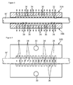
- the vacuum molding is to generate the pressure difference by reducing the pressure in the space outside the insulating coating 20, and is realized, for example, by the use of a upper metal mold 30A and a lower metal mold 30B as shown in Figs. 3 and 4 (Fig. 4 shows only the lower metal mold 30B).
- the upper metal mold 30A and the lower metal mold 30B have the shapes of sandwiching only the portion, shown in Figs. 3 and 4 , of the insulating coated wire material W' in which the bending auxiliary section is to be formed, and the portion in the vicinity thereof from above and below.
- each of the metal molds 30A and 30B have two end sections in the axial direction and a central section in the axial direction, the end sections and the central section having the different shapes.
- the two end sections in the axial direction each have a half inner circumferential surface 32 having a semi-circular cross-section that corresponds to the outer circumferential surface of the insulating coated wire material W'.
- the central section in the axial direction has the shape corresponding to the shape of the outer surface of the bending auxiliary section 24 that is to be formed, that is, has inner surfaces 36 and 38 that protrude outward in the radial direction with the sizes that correspond to the protrusion sizes of the large diameter sections 26 and the small diameter sections 28.
- each of the upper metal mold 30A and the lower metal mold 30B is provided with a plurality of air suction holes 34, which are communicated with a plurality of portions of the internal surface 32 (in the example shown in Figs. 3 and 4 , the inner surfaces 36 that correspond to the large diameter sections 26, that is, the inner surfaces that farther protrude outward in the radial direction) and are communicated with a common vacuum pump (not shown).
- each of the metal molds 30A and 30B has bolt insertion holes 39 (only shown with respect to the lower metal mold 30B of Fig. 4 ) into which a bolt for fastening the metal molds is inserted.
- the insulating coated wire material W' is sandwiched between the two metal molds 30A and 30B so that only the inner circumferential surfaces 32 of the upper metal mold 30A and the lower metal mold 30B that are formed at the two ends in the axial direction thereof are in close contact with the outer circumferential surface (the outer circumferential surface of the insulating coating 20) of the insulating coated wire material W' over the entire circumference thereof, and the metal molds 30A and 30B are fastened.
- both metal molds 30A and 30B are arranged on the circumference of the insulating coated wire material W'.
- a thermoplastic resin constituting the insulating coating 20 is heated to the softening temperature or more (for example, 100°C to 130°C in the case of vinyl chloride) using, for example, heaters that are mounted in the metal molds 30A and 30B.
- This pressure difference deforms the insulating coating 20 that is heated and softened within the metal molds 30A and 30B into the shape of being in close contact with the internal surfaces of the metal molds 30A and 30B (that is, the insulating coating 20 protrude into the shape corresponding to the inner circumferential surfaces of the metal molds).
- the bending auxiliary section 24 that has a thickness that is smaller than that of the normal diameter section 22, and includes the large diameter sections 26 and the small diameter sections 28. With this, the insulating coated wire W having the bending auxiliary section 24 is manufactured.
- an O-ring for example, may also be interposed between the insulating coating 20 and the inner circumferential surfaces 32.
- a rubber sheet may also be interposed between the metal molds 30A and 30B in order to seal the joint surfaces of the metal molds 30A and 30B.
- elongated metal molds for sealing the entire electrical wire material W may also be used.
- the blow molding is to generate the pressure difference by injecting pressure gas (for example, air) into the inside of the insulating coating 20 to increase the pressure inside the insulating coating 20, and is realized by the use of a metal mold device shown in, for example, Figs. 5 to 7 .
- pressure gas for example, air
- This metal mold device includes a central metal mold 40A, and an front metal mold 40B and a rear metal mold 40C that are arranged sequentially in front and rear of the central metal mold 40A.
- Each of the metal molds 40A to 40C is separated into right and left molds constituting a pair of half molds, and each half mold has bolt insertion holes 49 through which a bolt for fastening the half molds is inserted.
- the central metal mold 40A has the shape of sandwiching only the portion, shown in Figs. 5 and 6 , of the insulating coated wire material W' in which the bending auxiliary section is to be formed.
- the central metal mold 40A has an inner circumferential surface 42A in the shape corresponding to the shape of the outer surface of the bending auxiliary section 24 that is to be formed, that is, an inner circumferential surface that includes inner surfaces 46, 48 that protrude outward in the radial direction with the sizes that correspond to the protrusion sizes of the plurality of large diameter sections 26 and the small diameter sections 28 that are included in the bending auxiliary section 24.
- the front metal mold 40B and the rear metal mold 40C respectively have inner circumferential surfaces in the shapes of externally constraining the sections located in front and rear of the bending auxiliary section 24, that is, the sections serving as normal diameter sections 22.
- the front metal mold 40B and the rear metal mold 40C respectively have inner circumferential surfaces 42B and 42C that have diameters so as to be in close contact or substantially in close contact with the outer circumferential surface of the insulating coated wire material W'.
- a gas supply pipe 50 for injecting gas into the inside of the insulating coating 20 is connected to the rear metal mold 42C via a seal member 52, and a blower or pump for discharging pressure gas is connected to the gas supply pipe 50.
- the seal member 52 is arranged at an outer end of the rear metal mold 40C so as to cover the end surfaces of the insulating coating 20 and the center conductor 10 over the border thereof, in order to guide gas supplied from the gas supply pipe 50 only to the inside of the insulating coating 20 (that is, in order to prevent gas from escaping to the outside of the insulating coating 20).
- the metal mold device is arranged so that the portion of the insulating coated wire material W' in which the bending auxiliary section 24 is to be formed is sandwiched by the central metal mold 40A from right and left, and portions in front and rear of that portion are sandwiched respectively by the front metal mold 40B and the rear metal mold 40C from right and left.
- the portion of the insulating coating 20 that is located in the central metal mold 40A is locally heated to the softening temperature or more using, for example, heaters mounted in the central metal mold 40A.
- This pressure difference deforms the insulating coating 20 that is heated and softened within the central metal mold 40A into the shape of being in close contact with the internal surface 42A of the central metal mold 40A (that is, the insulating coating 20 protrudes into the shape corresponding to the inner circumferential surface 42A of the metal mold).
- the bending auxiliary section 24 including the large diameter sections 26 and the small diameter sections 28 is formed.
- the insulating coated wire W including the bending auxiliary section 24 is manufactured.
- the front metal mold 40B and the rear metal mold 40C which are shown in Figs. 5 and 6 , are preferably used in order to retain the shape of the section other than the bending auxiliary section 24 (normal diameter section 22), but the present invention is not limited to this. If the insulating coating 20 has a relatively high hardness at normal temperature, and protrusion thereof due to injection of the pressure gas is negligible small, the front and rear metal molds 40B and 40C can be omitted.
- these front and rear metal molds 40B and 40C may constrain the insulating coated wire material W' not over the entire length thereof but only the portion in the vicinity of the bending auxiliary section 24, that is, only the portion that has the risk of being thermally affected by heating of the central metal mold 40A and softened.
- the manufacturing method only by arranging a metal mold having an appropriately shaped inner surface on the circumference of the insulating coated wire material W', and generating a pressure difference between the inside and the outside of the insulating coating 20 in the metal mold while heating the insulating coating 20, it is possible to form an appropriate bending auxiliary section 24 on the insulating coating 20.
- the shape of the inner surface of the metal mold corresponds to the shape of the bending auxiliary section 24 obtained using the metal mold, it is possible to arbitrarily form the bending auxiliary section 24 in an appropriate shape by setting the shape of the inner surface of the metal mold. In other words, the formation of the bending auxiliary section in the required shape can easily be achieved by using the metal mold in the shape corresponding to this shape.
- an insulating coated wire that can be bent at an appropriate portion without requiring a troublesome operation and a complicated structure, and a method for easily manufacturing the insulating coated wire are provided.
- the insulating coated wire provided by the present invention includes a center conductor and an insulating coating that is made of an insulating synthetic resin material and covers the center conductor.
- the insulating coating includes a bending auxiliary section that is formed at a part in the axial direction thereof and has a thickness that is smaller than that of the other portion, the bending auxiliary section having a shape in which at least a part thereof protrudes outward in the radial direction of the insulating coating electrical wire, and that facilitates bending of the insulating coated wire by elongation deformation thereof.
- the method provided by the present invention is a method for manufacturing the insulating coated wire, including the steps of preparing an insulating coated wire material that includes a center conductor and an insulating coating that is made of an insulating thermoplastic resin material and covers the center conductor; arranging metal molds on the circumference of at least a part in the axial direction of the insulating coated wire material, the metal molds having inner surfaces that have sections in the shape of protruding outward in the radial direction with respect to the outer circumferential surface of the insulating coated wire material; and forming, on the insulating coating, the bending auxiliary section that has the shape along the inner surfaces of the metal molds, by generating a pressure difference in which a pressure inside the insulating coating is higher than a pressure outside the insulating coating within the metal molds in a state in which the insulating coating is heated within the metal molds to a temperature at which the thermoplastic resin material constituting the insulating coating is softened, the bending auxiliary section being such that
- the insulating coated wire having the bending auxiliary section it is possible to facilitate bending of the insulating coating electrical wire at a position that corresponds to the bending auxiliary section by elongation deformation of the thin insulating coating that constitutes the bending auxiliary section. That is, easy bendability of this insulating coated wire is achieved by elongation of the bending auxiliary section that is formed on the insulating coating itself constituting the insulating coated wire. Therefore, the operation for removing a part of the insulating coating or the operation for mounting the part from which the insulating coating is removed on a protector, which is a member separate from the insulating coated wire, as needed in the conventional case, are not necessary.
- the bending auxiliary section preferably includes at least one entire circumference protruding section that has inner and outer diameters larger than those of the section other than the bending auxiliary section due to protruding over the entire circumference of the insulating coated wire.
- the bending auxiliary section that includes the entire circumference protruding section having that shape can improve the easy bendability of the insulating coated wire in any direction.
- the bending auxiliary section further preferably includes a plurality of large diameter sections that have inner and outer diameters larger than those of the section other than the bending auxiliary section due to protruding over the entire circumference at a plurality of positions that are aligned intermittently in the axial direction of the insulating coated wire, and a small diameter section that is located between adjacent large diameter sections of these large diameter sections and has inner and outer diameters smaller than those of the large diameter sections, in an alternating manner, these large diameter sections and the small diameter section forming an accordion shape as a whole.
- the section in which the plurality of large diameter sections and small diameter sections are arranged in such an alternating manner can efficiently be subjected to elongation deformation so as to allow the insulating coated wire to be bent, making the easy bendability of the bending auxiliary section notable.
- the small diameter section may have the same outer and inner diameters as those of the section of the insulating coating other than the bending auxiliary section, or may have outer and inner diameters larger than those of the section other than the bending auxiliary section.
- the method for manufacturing the insulating coated wire it is possible to form an appropriate bending auxiliary section on the insulating coating by simple operations of arranging metal mold on the circumference of the insulating coated wire material, and generating a pressure difference between the inside and the outside of the insulating coating within the metal mold while heating the insulating coating.
- the shape of the inner surfaces of the metal mold corresponds to the shape of the bending auxiliary section obtained using the metal mold, it is possible to arbitrarily form the bending auxiliary section in an appropriate shape by setting the shape of the inner surfaces of the metal mold.
- the pressure difference between a pressure inside the insulating coating and a pressure outside the insulating coating within the metal mold can be generated not only by exhausting air in the metal mold and reducing the pressure but also by injecting gas such as air into the inside of the insulating coating heated inside the metal mold from at least one end of the insulating coated wire material.
Landscapes
- Engineering & Computer Science (AREA)
- Mechanical Engineering (AREA)
- Physics & Mathematics (AREA)
- Spectroscopy & Molecular Physics (AREA)
- Manufacturing & Machinery (AREA)
- Insulated Conductors (AREA)
- Processes Specially Adapted For Manufacturing Cables (AREA)
Applications Claiming Priority (2)
| Application Number | Priority Date | Filing Date | Title |
|---|---|---|---|
| JP2012273242A JP5605424B2 (ja) | 2012-12-14 | 2012-12-14 | 絶縁被覆電線の製造方法 |
| PCT/JP2013/003613 WO2014091637A1 (ja) | 2012-12-14 | 2013-06-07 | 絶縁被覆電線及びその製造方法 |
Publications (2)
| Publication Number | Publication Date |
|---|---|
| EP2933801A1 true EP2933801A1 (de) | 2015-10-21 |
| EP2933801A4 EP2933801A4 (de) | 2016-03-09 |
Family
ID=50933952
Family Applications (1)
| Application Number | Title | Priority Date | Filing Date |
|---|---|---|---|
| EP13862878.9A Withdrawn EP2933801A4 (de) | 2012-12-14 | 2013-06-07 | Beschichteter isolierdraht und verfahren zur herstellung davon |
Country Status (5)
| Country | Link |
|---|---|
| US (1) | US9620260B2 (de) |
| EP (1) | EP2933801A4 (de) |
| JP (1) | JP5605424B2 (de) |
| CN (1) | CN104838451A (de) |
| WO (1) | WO2014091637A1 (de) |
Families Citing this family (7)
| Publication number | Priority date | Publication date | Assignee | Title |
|---|---|---|---|---|
| DE102014226335A1 (de) * | 2014-12-17 | 2016-06-23 | Leoni Kabel Holding Gmbh | Verfahren zur Herstellung einer elektrischen Leitung, Werkzeugform für ein solches Verfahren und Leitung |
| JP6287867B2 (ja) * | 2015-01-07 | 2018-03-07 | 株式会社オートネットワーク技術研究所 | 電線及び端子付電線 |
| JP6555135B2 (ja) * | 2016-01-12 | 2019-08-07 | 株式会社オートネットワーク技術研究所 | 車両用配線構造及びその製造方法 |
| JP6624454B2 (ja) * | 2016-06-01 | 2019-12-25 | 住友電装株式会社 | グロメット及びワイヤハーネス |
| JP7147839B2 (ja) * | 2018-03-28 | 2022-10-05 | 株式会社オートネットワーク技術研究所 | ワイヤーハーネスおよびワイヤーハーネスの製造方法 |
| WO2020152931A1 (ja) * | 2019-01-23 | 2020-07-30 | 本田技研工業株式会社 | 積層ワーク成形方法及びその装置 |
| CN114758834A (zh) * | 2022-03-14 | 2022-07-15 | 吉林省中赢高科技有限公司 | 一种电能传输系统及一种汽车 |
Family Cites Families (22)
| Publication number | Priority date | Publication date | Assignee | Title |
|---|---|---|---|---|
| US2760228A (en) * | 1952-02-19 | 1956-08-28 | Telecommunications Sa | Manufacture of tubular insulators for electric conductors |
| US3607387A (en) * | 1968-09-18 | 1971-09-21 | Raychem Corp | Flame resistant polyimide-coated conductor having a linear polyimide layer covered by an aromatic polyamide |
| FR2210022B1 (de) * | 1972-12-13 | 1977-09-02 | Telecommunications Sa | |
| DE2261530C3 (de) * | 1972-12-15 | 1976-01-02 | Fraenkische Isolierrohr- & Metallwaren-Werke, Gebr. Kirchner, 8729 Koenigsberg | Isolierrohr aus Kunststoff |
| JPS5912209U (ja) * | 1982-07-15 | 1984-01-25 | 株式会社フジクラ | 可「あ」性ケ−ブル |
| JPS5988820A (ja) | 1982-11-15 | 1984-05-22 | Ulvac Corp | シ−トプラズマを利用した化合物半導体薄膜製造装置 |
| JPS5988820U (ja) * | 1982-12-06 | 1984-06-15 | 三和電工株式会社 | 配線コ−ド |
| JPH0747283B2 (ja) * | 1985-03-22 | 1995-05-24 | 株式会社吉野工業所 | 成形素材管の取扱方法 |
| US4768481A (en) | 1987-07-24 | 1988-09-06 | Southwest Research Institute | Process and engine using compression ignition of a homogeneous fuel-air mixture |
| JPS6436917U (de) * | 1987-08-31 | 1989-03-06 | ||
| JPH02265107A (ja) * | 1989-04-04 | 1990-10-29 | Furukawa Electric Co Ltd:The | 曲がり部付多芯フラットケーブル及びその製造方法 |
| US4970351A (en) * | 1990-03-02 | 1990-11-13 | United Techologies Automotive, Inc. | Wiring harness conduit |
| JP2931216B2 (ja) | 1994-09-28 | 1999-08-09 | 矢崎総業株式会社 | 屈曲部を有する電線の配索方法 |
| JPH10697A (ja) * | 1996-06-14 | 1998-01-06 | Toutaku Kogyo Kk | 合成樹脂ホースとその製造方法 |
| JPH10257634A (ja) * | 1997-03-14 | 1998-09-25 | Sumitomo Wiring Syst Ltd | ワイヤハーネス外装用コルゲートチューブ |
| CN101384408B (zh) * | 2005-11-18 | 2013-10-09 | 艾伦·马克·克劳利 | 管的成型 |
| FR2893877B1 (fr) * | 2005-11-30 | 2009-10-09 | Roctool Soc Par Actions Simplifee | Procede de fabrication d'un tuyau ou tube annele |
| JP2007166770A (ja) * | 2005-12-13 | 2007-06-28 | Jimbo Electric Co Ltd | 配線用管材 |
| JP5322494B2 (ja) * | 2008-05-13 | 2013-10-23 | 矢崎総業株式会社 | 電線 |
| JP2010260241A (ja) * | 2009-05-01 | 2010-11-18 | Nitta Moore Co | コルゲートチューブおよびその製造方法 |
| JP5758087B2 (ja) * | 2010-06-02 | 2015-08-05 | 矢崎総業株式会社 | ワイヤハーネス |
| JP5768702B2 (ja) * | 2011-12-21 | 2015-08-26 | 住友電装株式会社 | ワイヤーハーネス |
-
2012
- 2012-12-14 JP JP2012273242A patent/JP5605424B2/ja not_active Expired - Fee Related
-
2013
- 2013-06-07 US US14/647,542 patent/US9620260B2/en not_active Expired - Fee Related
- 2013-06-07 CN CN201380064777.8A patent/CN104838451A/zh active Pending
- 2013-06-07 EP EP13862878.9A patent/EP2933801A4/de not_active Withdrawn
- 2013-06-07 WO PCT/JP2013/003613 patent/WO2014091637A1/ja not_active Ceased
Also Published As
| Publication number | Publication date |
|---|---|
| WO2014091637A1 (ja) | 2014-06-19 |
| JP2014120260A (ja) | 2014-06-30 |
| JP5605424B2 (ja) | 2014-10-15 |
| US20150310961A1 (en) | 2015-10-29 |
| EP2933801A4 (de) | 2016-03-09 |
| CN104838451A (zh) | 2015-08-12 |
| US9620260B2 (en) | 2017-04-11 |
Similar Documents
| Publication | Publication Date | Title |
|---|---|---|
| US9620260B2 (en) | Insulating coated wire and method for manufacturing the same | |
| US10431351B2 (en) | Flat cable and production method therefor | |
| JP5935709B2 (ja) | 保護部材及びワイヤーハーネス | |
| KR20150101154A (ko) | 플렉서블 버스바 | |
| CN103890861B (zh) | 线束以及线束的制造方法 | |
| KR20200116880A (ko) | 플렉서블 버스바 | |
| EP2755210B1 (de) | Kabelbaum und herstellungsverfahren für einen kabelbaum | |
| CN106063063A (zh) | 电线保护管 | |
| US20130161092A1 (en) | Wire harness | |
| US9520702B2 (en) | Clamp-integrated wiring harness protector for assembling and method for producing the same | |
| DE502005010004D1 (de) | Elektrischer Zuheizer für eine Heizungs- oder Klimaanlage eines Kraftfahrzeugs | |
| JP5954285B2 (ja) | 絶縁被覆電線及びその製造方法 | |
| JP5655971B2 (ja) | 絶縁被覆電線 | |
| JP2015103424A (ja) | 絶縁被覆電線及びその製造方法 | |
| JP6176120B2 (ja) | コネクタ及びその製造方法 | |
| JP2014123478A (ja) | 絶縁被覆電線及びその製造方法 | |
| US20160119978A1 (en) | Waterproofing structure for linear member | |
| JP6137008B2 (ja) | ワイヤハーネスの製造方法 | |
| JP2015103425A (ja) | 絶縁被覆電線及びその製造方法 | |
| US20250271091A1 (en) | Heater hose with multi-voltage functionality and constant power output | |
| KR101454708B1 (ko) | 열배관 감시시스템용 방수형 단자대, 단자 및 단자 어셈블리 | |
| WO2017212998A1 (ja) | コルゲートチューブ、ワイヤーハーネス及びコルゲートチューブの加工方法 | |
| JP2015103418A (ja) | 絶縁被覆電線及びその製造方法 | |
| JP6170819B2 (ja) | 絶縁被覆電線及びその製造方法 | |
| CN108162351A (zh) | 线束和线束的制造方法 |
Legal Events
| Date | Code | Title | Description |
|---|---|---|---|
| PUAI | Public reference made under article 153(3) epc to a published international application that has entered the european phase |
Free format text: ORIGINAL CODE: 0009012 |
|
| 17P | Request for examination filed |
Effective date: 20150714 |
|
| AK | Designated contracting states |
Kind code of ref document: A1 Designated state(s): AL AT BE BG CH CY CZ DE DK EE ES FI FR GB GR HR HU IE IS IT LI LT LU LV MC MK MT NL NO PL PT RO RS SE SI SK SM TR |
|
| AX | Request for extension of the european patent |
Extension state: BA ME |
|
| A4 | Supplementary search report drawn up and despatched |
Effective date: 20160209 |
|
| RIC1 | Information provided on ipc code assigned before grant |
Ipc: B29D 23/00 20060101ALN20160203BHEP Ipc: B29C 51/12 20060101ALI20160203BHEP Ipc: H01B 7/04 20060101ALN20160203BHEP Ipc: H01B 13/06 20060101ALN20160203BHEP Ipc: B29C 51/10 20060101AFI20160203BHEP |
|
| DAX | Request for extension of the european patent (deleted) | ||
| STAA | Information on the status of an ep patent application or granted ep patent |
Free format text: STATUS: EXAMINATION IS IN PROGRESS |
|
| 17Q | First examination report despatched |
Effective date: 20180724 |
|
| STAA | Information on the status of an ep patent application or granted ep patent |
Free format text: STATUS: THE APPLICATION HAS BEEN WITHDRAWN |
|
| 18W | Application withdrawn |
Effective date: 20181119 |