EP2932875A1 - Isolierkanne - Google Patents
Isolierkanne Download PDFInfo
- Publication number
- EP2932875A1 EP2932875A1 EP15154682.7A EP15154682A EP2932875A1 EP 2932875 A1 EP2932875 A1 EP 2932875A1 EP 15154682 A EP15154682 A EP 15154682A EP 2932875 A1 EP2932875 A1 EP 2932875A1
- Authority
- EP
- European Patent Office
- Prior art keywords
- thread
- jug
- range
- jacket
- pot
- Prior art date
- Legal status (The legal status is an assumption and is not a legal conclusion. Google has not performed a legal analysis and makes no representation as to the accuracy of the status listed.)
- Granted
Links
- 238000004519 manufacturing process Methods 0.000 claims abstract description 8
- 229920001187 thermosetting polymer Polymers 0.000 claims description 16
- 229920001807 Urea-formaldehyde Polymers 0.000 claims description 6
- 239000000463 material Substances 0.000 claims description 5
- 229920003180 amino resin Polymers 0.000 claims description 3
- 238000007789 sealing Methods 0.000 description 6
- UMGDCJDMYOKAJW-UHFFFAOYSA-N thiourea Chemical class NC(N)=S UMGDCJDMYOKAJW-UHFFFAOYSA-N 0.000 description 6
- XSQUKJJJFZCRTK-UHFFFAOYSA-N Urea Chemical compound NC(N)=O XSQUKJJJFZCRTK-UHFFFAOYSA-N 0.000 description 5
- 239000000203 mixture Substances 0.000 description 5
- 150000003672 ureas Chemical class 0.000 description 4
- WSFSSNUMVMOOMR-UHFFFAOYSA-N Formaldehyde Chemical compound O=C WSFSSNUMVMOOMR-UHFFFAOYSA-N 0.000 description 3
- 229920000877 Melamine resin Polymers 0.000 description 3
- 235000013877 carbamide Nutrition 0.000 description 3
- 239000002184 metal Substances 0.000 description 3
- 229920000965 Duroplast Polymers 0.000 description 2
- 239000004638 Duroplast Substances 0.000 description 2
- 239000004640 Melamine resin Substances 0.000 description 2
- 239000011521 glass Substances 0.000 description 2
- 230000003678 scratch resistant effect Effects 0.000 description 2
- 229920001169 thermoplastic Polymers 0.000 description 2
- 239000004416 thermosoftening plastic Substances 0.000 description 2
- AVQQQNCBBIEMEU-UHFFFAOYSA-N 1,1,3,3-tetramethylurea Chemical compound CN(C)C(=O)N(C)C AVQQQNCBBIEMEU-UHFFFAOYSA-N 0.000 description 1
- IFIDZFJWVZBCCV-UHFFFAOYSA-N 1,3-bis(2-methylpropyl)urea Chemical compound CC(C)CNC(=O)NCC(C)C IFIDZFJWVZBCCV-UHFFFAOYSA-N 0.000 description 1
- AQSQFWLMFCKKMG-UHFFFAOYSA-N 1,3-dibutylurea Chemical compound CCCCNC(=O)NCCCC AQSQFWLMFCKKMG-UHFFFAOYSA-N 0.000 description 1
- ZWAVGZYKJNOTPX-UHFFFAOYSA-N 1,3-diethylurea Chemical compound CCNC(=O)NCC ZWAVGZYKJNOTPX-UHFFFAOYSA-N 0.000 description 1
- OIFBSDVPJOWBCH-UHFFFAOYSA-N Diethyl carbonate Chemical compound CCOC(=O)OCC OIFBSDVPJOWBCH-UHFFFAOYSA-N 0.000 description 1
- KMTRUDSVKNLOMY-UHFFFAOYSA-N Ethylene carbonate Chemical compound O=C1OCCO1 KMTRUDSVKNLOMY-UHFFFAOYSA-N 0.000 description 1
- MGJKQDOBUOMPEZ-UHFFFAOYSA-N N,N'-dimethylurea Chemical compound CNC(=O)NC MGJKQDOBUOMPEZ-UHFFFAOYSA-N 0.000 description 1
- 230000009286 beneficial effect Effects 0.000 description 1
- 239000004202 carbamide Substances 0.000 description 1
- 150000004651 carbonic acid esters Chemical class 0.000 description 1
- 239000007795 chemical reaction product Substances 0.000 description 1
- 238000000748 compression moulding Methods 0.000 description 1
- QGBSISYHAICWAH-UHFFFAOYSA-N dicyandiamide Chemical compound NC(N)=NC#N QGBSISYHAICWAH-UHFFFAOYSA-N 0.000 description 1
- IEJIGPNLZYLLBP-UHFFFAOYSA-N dimethyl carbonate Chemical compound COC(=O)OC IEJIGPNLZYLLBP-UHFFFAOYSA-N 0.000 description 1
- 150000002148 esters Chemical class 0.000 description 1
- 230000001747 exhibiting effect Effects 0.000 description 1
- 238000002474 experimental method Methods 0.000 description 1
- 239000012530 fluid Substances 0.000 description 1
- HANVTCGOAROXMV-UHFFFAOYSA-N formaldehyde;1,3,5-triazine-2,4,6-triamine;urea Chemical compound O=C.NC(N)=O.NC1=NC(N)=NC(N)=N1 HANVTCGOAROXMV-UHFFFAOYSA-N 0.000 description 1
- CGXBXJAUUWZZOP-UHFFFAOYSA-N formaldehyde;phenol;1,3,5-triazine-2,4,6-triamine Chemical compound O=C.OC1=CC=CC=C1.NC1=NC(N)=NC(N)=N1 CGXBXJAUUWZZOP-UHFFFAOYSA-N 0.000 description 1
- 238000003780 insertion Methods 0.000 description 1
- 230000037431 insertion Effects 0.000 description 1
- 230000013011 mating Effects 0.000 description 1
- JDSHMPZPIAZGSV-UHFFFAOYSA-N melamine Chemical compound NC1=NC(N)=NC(N)=N1 JDSHMPZPIAZGSV-UHFFFAOYSA-N 0.000 description 1
- 238000000034 method Methods 0.000 description 1
- 238000007649 pad printing Methods 0.000 description 1
- 229920001568 phenolic resin Polymers 0.000 description 1
- 239000004033 plastic Substances 0.000 description 1
- 229920003023 plastic Polymers 0.000 description 1
- 229920000728 polyester Polymers 0.000 description 1
- 239000000843 powder Substances 0.000 description 1
- 238000003825 pressing Methods 0.000 description 1
- RUOJZAUFBMNUDX-UHFFFAOYSA-N propylene carbonate Chemical compound CC1COC(=O)O1 RUOJZAUFBMNUDX-UHFFFAOYSA-N 0.000 description 1
- 238000007650 screen-printing Methods 0.000 description 1
- 238000003860 storage Methods 0.000 description 1
- 239000012815 thermoplastic material Substances 0.000 description 1
- 150000003585 thioureas Chemical class 0.000 description 1
Images


Classifications
-
- A—HUMAN NECESSITIES
- A47—FURNITURE; DOMESTIC ARTICLES OR APPLIANCES; COFFEE MILLS; SPICE MILLS; SUCTION CLEANERS IN GENERAL
- A47J—KITCHEN EQUIPMENT; COFFEE MILLS; SPICE MILLS; APPARATUS FOR MAKING BEVERAGES
- A47J41/00—Thermally-insulated vessels, e.g. flasks, jugs, jars
- A47J41/02—Vacuum-jacket vessels, e.g. vacuum bottles
Definitions
- the invention relates to a jug body for a jug, the jug itself and a method for producing the jug.
- the jug body of Isolierkannen is made of thermoplastic materials or metal.
- Metallic can bodies are relatively heavy.
- Thermoplastic can bodies deform easily when exposed to heat.
- the decors have been applied to the cans by screen printing or pad printing. As a result, the decors were not yet scratch-resistant, not very dishwasher-safe and are often quickly yellowed.
- CN 2037199 U and CN 1042518 A describe insulating jugs without thread in the lower part of the jug body.
- the object of the present invention is to provide a jug body which is light and at the same time relatively heat-stable.
- cans and in particular jugs with temperature-independent torsional stiffness can be provided.
- thermos jugs made of thermosets since the modern jugs as a footprint have a screwed into the jacket bottom part.
- the associated screw thread of the shell is inevitably destroyed in forced removal by the brittleness of the thermosets.
- thermosetting plastic a jug can be decorated with a jug body according to the invention, for example, much more flexible and durable. Preferred embodiments of the decor are described below.
- the thermoset is an aminoplast, more preferably a urea resin.
- the aminoplast may, for example, be selected from melamine resin, melamine-phenol-formaldehyde resin (MPF), melamine-urea-formaldehyde resins (UMF), melamine-polyester, urea-resin, dicyandiamide, or mixtures thereof.
- Urea resin is particularly preferred since, for example, it is more resistant to breakage than melamine.
- thermoset is preferably a reaction product of a starting composition containing on the one hand formaldehyde and on the other hand urea and / or urea derivative.
- substituted ureas, thiourea, substituted thioureas and carbonic esters are preferred. More preferred are the substituted ureas, thiourea and the carbonic acid esters. Preferred among these are thiourea, N, N'-dimethylurea, N, N'-diethylurea, N, N'-di-n-butylurea, N, N'-diisobutylurea, N, N, N ', N'-tetramethylurea, dimethyl carbonate , Diethyl carbonate, ethylene carbonate and 1,2-propylene carbonate.
- the starting composition may also contain pulp and / or pulp.
- the thermoset preferably contains pulp and / or pulp in an amount in a range of from 10 to 50% by weight, more preferably in a range of from 20 to 40% by weight. As a result, the thermoset is particularly insensitive to mechanical influences.
- the starting composition may be a powder.
- At least part of the jacket of the can body is made of a thermosetting plastic.
- the pot body is preferably made of a thermoset, at least in the region of the thread.
- the jacket of the jug body is made of duroplastic. This has the particular advantage that the jug can be particularly light and heat resistant at the same time.
- the shell of the jug body preferably has a wall thickness in a range of 1 to 4 mm, more preferably in a range of 1.5 to 3 mm, at least over 80% of the outer shell surface.
- the jacket preferably has a thread at its lower end. This thread can accommodate the ground insert.
- the thread pitch of the thread is in a range of 2 to 8 mm.
- the thread is a trapezoidal thread, more preferably a rounded trapezoidal thread.
- the flank angle is preferably in a range of 35 ° to 60 °. It has been found that this results in a particularly low resistance to the demolding of the shell.
- the thread depth of the first thread of the thread is from the lower edge of the pot body in a range of 0.4 to 4 mm, more preferably in a range of 1 to 1.7 mm.
- the bottom plate can be kept very firm and secure in the bottom of the shell.
- the thread depth of the first thread of the thread from the lower edge of the pot body is deeper than the thread depth of the last thread of the thread from the lower edge of the pot body.
- the thread preferably has 3 to 7 threads.
- the thread is clockwise.
- the finished coat can be easily and intuitively removed from the mold by rotation.
- the can body and in particular the jacket can preferably have two opposite recesses at the upper edge.
- the recesses have a depth in a range of 2 to 15 mm, more preferably in a range of 6 to 9 mm.
- the recesses have a width in a range of 1 to 10 mm, more preferably in a range of 3 to 7 mm. This makes it possible to remove the jacket from the mold very easily after production by, for example, laying a rod in the recesses and rotating.
- the coat can also have a decor.
- This decor can be inserted into the mold during manufacture.
- a printed decor for example, on a paper, are placed in the mold and then provided with a thin layer of starting composition and then pressed in the mold with the jacket optionally under the action of heat.
- thermoset over the decor, which ensures that the so decorated jacket of a pot are much scratch resistant than the printed thermoplastic coats of the prior art.
- the decors so applied are much dishwasher safe and do not turn yellow so quickly.
- the layer of thermoset over the decor or the decorative layer preferably has a thickness in a range of 10 to 400 microns.
- the object underlying the invention is achieved by an insulating jug, with a jug body according to the invention, a spout and a lid.
- a jug body according to the invention, a spout and a lid.
- an insulating piston can be arranged in the jug body and an insulating piston can be arranged.
- the jug body may, for example, have a jacket and possibly also a bottom insert. This bottom insert may for example be screwed into the shell or in the lower opening.
- the interior can be formed by an insulating piston inserted into a jug body, which has a receiving opening at its upper end.
- an insulating piston can be a double-walled, evacuated and mirrored glass bulb, a double-walled and evacuated metal piston or a single-walled, glass, metal or plastic piston.
- a spout exhibiting headpiece is releasably secured on a can top and in sealing position with a surrounding the receiving opening edge region in sealing system.
- the entire head piece can be removed, for example, to replace the insulating piston.
- the head piece can be bolted or latched to the top of the can.
- a fixation of the insulating piston within the jug body and a seal can be done simultaneously by the head piece.
- the seal between the head and the insulating can be done in different ways.
- An example is the arrangement of a seal between the head piece and edge region of the receiving opening of the insulating piston.
- the handle In connection with the head piece, it may prove to be beneficial if this and the handle are integrally formed. In this way, the handle can be used on the one hand for rotating the head piece relative to the jug body or insulating piston.
- a guide channel In a simple embodiment of a guide channel, the latter can connect the spout projecting laterally from the head piece with the receiving opening through the head piece, the guide channel in particular having a substantially circular cross section and running vertically.
- the guide channel is automatically assigned to the receiving opening and connected liquid-tight with this.
- the guide channel has other cross-sectional shapes, such as angular or oval, in which connection the closure element is shaped accordingly.
- the guide channel for example, also run obliquely between the receiving opening and spout.
- the lid Regardless of the cross section of the guide channel, it is advantageous for a simple attachment of the lid when an upper channel end of the guide channel is at least partially surrounded by a screw-on ring onto which the lid can be screwed in particular. By screwing it is further ensured that a closure element is correctly positioned for closing and opening in particular of the guide channel.
- the lid it is possible for the lid to be plugged in the exact position, wherein the closure element can also be designed such that it closes the guide channel as a whole in the closed position and, in the open position, opens the latter overall in the direction of the spout.
- a simple embodiment of a lid can be seen in that the lid has a substantially annular lower part for the storage of closure and VerInstitutverstellelement and a patch on the lower part cap.
- the cap can also be releasably attached to the lower part.
- the lower part may have a threaded ring provided with an external thread for screwing into the Aufschraubring and a radially at the upper end of the screw ring outwardly projecting support ring.
- the lower part can be screwed by means of the screw ring so far into the screw-on until the support ring rests with its underside at the upper end of the Aufschraubrings. In this position, it is then ensured, for example, that, on the one hand, the closure element is correctly positioned and, on the other hand, a liquid-tight seal of the interior with respect to the spout is ensured in its closed position.
- connection between the closure element and the lid can be done in different ways.
- the closure element could be designed as a closure cap similar to the pot described above, which is mounted pivotably in the lid at one end according to the invention.
- the closure element can have a plate-shaped sealing plate, from the underside of which an insertion ring which can be inserted into the guide channel or into the receiving opening protrudes.
- the content of the pot targeted to the spout to be able to have the Einsteckring have at least one the spout assigning radial opening. Through this, the content of the pot flows in the direction of spout, while the amount of effluent material can be limited.
- the handle may have in its interior a cavity in which the trigger formed essentially of a spring band is arranged.
- the trigger As an actuating element for the trigger is the spring band in the direction of pot from the handle, a trigger element.
- the spring band By pressing the trigger element towards the handle, the spring band is substantially moved away from the pot and applied to an inside of the cavity.
- the spring band By adjusting the spring band whose engagement end is also moved radially outward with respect to the lid and pivoted about the movement connection with the connecting part and its connection via the belt to the bearing part about its pivot axis in the counterclockwise direction.
- the carrying end is moved in the direction of the closure cap and the closing connection is made via the movement connection by means of the bearing arms moved up against the resilient action of the bellows member, whereby a fluid connection between the receiving opening and spout is made.
- a return of the closure element is effected in particular by the bellows element, wherein the provision of the closure element as well as the bearing part and connecting part is supported by the elasticity of the spring band of the trigger.
- the object underlying the invention is achieved by a method for producing a jug body, characterized in that the jug body is removed during removal from a thread of a mold, which engages in the thread of the jug body.
- a pot according to the invention and in particular an insulating jug according to the invention are produced.
- the production of the jacket 28 according to the invention will be briefly described below. It will be discussed primarily on the invention essential and preferred features. Incidentally, the jacket 28, such as in US 2,791,573 A or EP 0051821 A1 be prepared described.
Landscapes
- Physics & Mathematics (AREA)
- Thermal Sciences (AREA)
- Engineering & Computer Science (AREA)
- Food Science & Technology (AREA)
- Table Devices Or Equipment (AREA)
- Cookers (AREA)
Abstract
Description
- Die Erfindung betrifft einen Kannenkörper für eine Isolierkanne, die Isolierkanne selbst und ein Verfahren zur Herstellung der Isolierkanne.
- Bislang wird der Kannenkörper von Isolierkannen aus thermoplastischen Werkstoffen oder aus Metall gefertigt. Metallische Kannenkörper sind relativ schwer. Thermoplastische Kannenkörper verformen leicht bei Hitzeeinwirkung. Auf die Kannen wurden die Dekore bislang über Siebdruck oder Tampondruck aufgebracht. Dadurch waren die Dekore bislang nicht kratzfest, nicht sehr spülmaschinenfest und sind oft schnell vergilbt.
-
CN 202497017 U ,CN 2037199 U undCN 1042518 A beschreiben Isolierkannen ohne Gewinde im unteren Bereich des Kannenkörpers. - Die Aufgabe der vorliegenden Erfindung besteht darin, einen Kannenkörper bereitzustellen, der leicht und gleichzeitig relativ hitzestabil ist.
- Die der Erfindung zugrunde liegende Aufgabe wird in einer ersten Ausführungsform durch einen Kannenkörper für eine Kanne, insbesondere eine Isolierkanne, gelöst, wobei
- a. im unteren Bereich des Kannenkörpers ein Gewinde angeordnet ist, und
- b. wenigstens ein Teil des Kannenkörpers aus einem Material besteht, das überwiegend einen Duroplast enthält.
- Dadurch können Kannen und insbesondere Isolierkannen mit temperaturunabhängiger Verwindungssteifigkeit bereitgestellt werden.
- Gegenstände aus Duroplast wie Melaminharz werden bislang aus dem Pressformen über Zwangsentformung entfernt. Daher erschien es bislang als unmöglich, moderne Isolierkannen aus Duroplasten herzustellen, da die modernen Isolierkannen als Stellfläche ein in den Mantel eingeschraubtes Bodenteil aufweisen. Das zugehörige Schraubgewinde des Mantels wird bei Zwangsentformung durch die Sprödigkeit der Duroplaste zwangsläufig zerstört.
- Daher gab es bislang das Vorurteil, dass der Mantel herkömmlicher Isolierkannen mit einem eingeschraubten Bodeneinsatz nicht aus Duroplasten hergestellt werden kann. Dieses jahrzehntealte Vorurteil haben die Erfinder in der vorliegenden Erfindung überwunden und erfolgreich einen Mantel einer Isolierkanne beispielsweise ganz aus Duroplast hergestellt. Die Erfinder haben herausgefunden, dass sich auch für Duroplaste Formen mit einem Ausdrehkern realisieren lassen, so dass beispielsweise ein Mantel für eine Isolierkanne aus Duroplast aus einer Form ausgedreht werden kann.
- Duch den Anteil an Duroplast kann eine Kanne mit einem erfindungsgemäßen Kannenkörper auch beispielsweise wesentlich flexibler und haltbarer dekoriert werden. Bevorzugte Ausführungsformen des Dekors sind unten beschrieben.
- Vorzugsweise ist der Duroplast ein Aminoplast, besonders bevorzugt ein Harnstoffharz. Der Aminoplast kann beispielsweise ausgewählt sein aus Melaminharz, Melamin-Phenol-Formaldehyd-Harz (MPF), Melamin-Harnstoff-Formaldehyd-Harze (UMF), Melamin-Polyester, Harnstoffharz, Dicyandiamid, oder Mischungen derselben. Harnstoffharz ist besonders bevorzugt, da es beispielsweise gegenüber Melamin beständiger gegen Bruch ist.
- Der Duroplast ist vorzugsweise ein Reaktionsprodukt aus einer Ausgangszusammensetzung, die einerseits Formaldehyd und andererseits Harnstoff und/oder Harnstoffderivat enthält.
- Unter den oben genannten Harnstoffderivaten sind substituierte Harnstoffe, Thioharnstoff, substituierte Thioharnstoffe und die Kohlensäureester bevorzugt. Stärker bevorzugt sind die substituierten Harnstoffe, Thioharnstoff und die Kohlensäureester. Bevorzugt sind hierunter Thioharnstoff, N,N'-Dimethylharnstoff, N,N'-Diethylharnstoff, N,N'-Di-n-butylharnstoff, N,N'-Diisobutylharnstoff, N,N,N',N'-tetramethylharnstoff, Dimethylcarbonat, Diethylcarbonat, Ethylencarbonat und 1,2-Propylencarbonat.
- Die Ausgangszusammensetzung kann auch Faserstoff und/oder Zellstoff enthalten. Der Duroplast enthält vorzugsweise Faserstoff und/oder Zellstoff in einer Menge in einem Bereich von 10 bis 50 Gew.%, besonders bevorzugt in einem Bereich von 20 bis 40 Gew.%. Dadurch ist der Duroplast besonders unempfindlich gegen mechanische Einflüsse.
- Die Ausgangszusammensetzung kann ein Pulver sein.
- Vorzugsweise ist wenigstens ein Teil des Mantels des Kannenkörpers aus einem Duroplast.
- Der Kannenkörper besteht vorzugsweise zumindest im Bereich des Gewindes aus einem Duroplast.
- Vorzugsweise besteht der Mantel des Kannenkörpers aus Duroplast. Dies hat den besonderen Vorteil, dass die Isolierkanne besonders leicht und gleichzeitig hitzebeständig sein kann.
- Der Mantel des Kannenkörpers hat vorzugsweise zumindest über 80 % der Mantelaußenfläche eine Wandstärke in einem Bereich von 1 bis 4 mm, besonders bevorzugt in einem Bereich von 1,5 bis 3 mm.
- Der Mantel weist vorzugsweise an seinem unteren Ende ein Gewinde auf. Dieses Gewinde kann den Bodeneinsatz aufnehmen.
- Vorzugsweise liegt die Gewindesteigung des Gewindes in einem Bereich von 2 bis 8 mm.
- Vorzugsweise ist das Gewinde ein Trapezgewinde, besonders bevorzugt ein gerundetes Trapezgewinde. Der Flankenwinkel liegt vorzugsweise in einem Bereich von 35° bis 60°. Es hat sich herausgestellt, dass sich dadurch bei der Entformung des Mantels ein besonders geringer Widerstand einstellt.
- Vorzugsweise liegt die Gewindetiefe des ersten Gewindeganges des Gewindes von der Unterkante des Kannenkörpers aus in einem Bereich von 0,4 bis 4 mm, besonders bevorzugt in einem Bereich von 1 bis 1,7 mm. Dadurch kann die Bodenplatte besonders fest und sicher im Boden des Mantels gehalten werden.
- Vorzugsweise ist die Gewindetiefe des ersten Gewindeganges des Gewindes von der Unterkante des Kannenkörpers aus tiefer als die Gewindetiefe des letzten Gewindeganges des Gewindes von der Unterkante des Kannenkörpers. Dadurch kann auch bei konischen Kannenkörpern der Bodeneinsatz gut durch das Gewinde festgehalten werden.
- Das Gewinde weist vorzugsweise 3 bis 7 Gewindegänge auf.
- Vorzugsweise ist das Gewinde rechtsdrehend. Dadurch kann der fertig hergestellte Mantel leicht und intuitiv aus der Form durch Drehung entformt werden.
- Der Kannenkörper und insbesondere der Mantel können am oberen Rand vorzugsweise zwei gegenüberliegende Ausnehmungen aufweisen. Vorzugsweise haben die Ausnehmungen eine Tiefe in einem Bereich von 2 bis 15 mm, besonders bevorzugt in einem Bereich von 6 bis 9 mm. Vorzugsweise haben die Ausnehmungen eine Breite in einem Bereich von 1 bis 10 mm, besonders bevorzugt in einem Bereich von 3 bis 7 mm. Dadurch kann man den Mantel sehr leicht nach der Herstellung aus der Form entformen, indem man beispielsweise eine Stange in die Ausnehmungen legt und dreht.
- Der Mantel kann auch ein Dekor aufweisen. Dieses Dekor kann bei der Herstellung in die Form eingelegt werden. Beispielsweise kann ein gedrucktes Dekor, beispielsweise auf einem Papier, in die Form eingelegt werden und anschließend mit einer dünnen Schicht Ausgangszusammensetzung versehen werden und anschließend in der Form mit dem Mantel gegebenenfalls unter Wärmeeinwirkung verpresst werden.
- Dadurch entsteht beispielsweise eine dünne Schicht aus Duroplast über dem Dekor, die dafür sorgt, dass der so dekorierte Mantel einer Kanne wesentlich kratzfester als die bedruckten thermoplastischen Mäntel des Standes der Technik sind. Zudem sind die so aufgebrachten Dekore wesentlich spülmaschinenfester und vergilben nicht so schnell.
- Die Schicht aus Duroplast über dem Dekor beziehungsweise der Dekorschicht weist vorzugsweise eine Dicke in einem Bereich von 10 bis 400 µm auf.
- In einer weiteren Ausführungsform wird die der Erfindung zugrunde liegende Aufgabe durch eine Isolierkanne gelöst, mit einem erfindungsgemäßen Kannenkörper, einem Ausguss und einem Deckel. Im Kannenkörper kann auch ein Isolierkolben angeordnet sein. Der Kannenkörper kann beispielsweise einen Mantel und gegebenenfalls auch einen Bodeneinsatz aufweisen. Dieser Bodeneinsatz kann beispielsweise in den Mantel oder in dessen unterer Öffnung eingeschraubt sein.
- Um in einfacher Weise eine Kanne und insbesondere eine Isolierkanne zu erhalten, kann der Innenraum von einem in einen Kannenkörper eingesetzten Isolierkolben gebildet sein, der an seinem oberen Ende eine Aufnahmeöffnung aufweist. Ein solcher Isolierkolben kann ein doppelwandiger, evakuierter und verspiegelter Glaskolben, ein doppelwandiger und evakuierter Metallkolben oder ein einwandiger, umschäumter Glas-, Metall-, beziehungsweise Kunststoffkolben sein.
- Weiterhin ist es als vorteilhaft anzusehen, wenn ein den Ausguss aufweisendes Kopfstück auf einer Kannenoberseite lösbar befestigt ist und in Befestigungsstellung mit einem die Aufnahmeöffnung umgebenden Randbereich in Dichtanlage ist. Auf diese Weise kann das gesamte Kopfstück beispielsweise zum Austausch des Isolierkolbens abgenommen werden. Das Kopfstück kann mit der Kannenoberseite verschraubt oder verrastet werden. Außerdem können durch das Kopfstück gleichzeitig eine Fixierung des Isolierkolbens innerhalb des Kannenkörpers und eine Abdichtung erfolgen.
- Die Abdichtung zwischen Kopfstück und Isolierkolben kann in unterschiedlicher Weise erfolgen. Ein Beispiel ist die Anordnung einer Dichtung zwischen Kopfstück und Randbereich der Aufnahmeöffnung des Isolierkolbens.
- Im Zusammenhang mit dem Kopfstück kann es sich als günstig erweisen, wenn dieses und der Handgriff einteilig ausgebildet sind. Auf diese Weise kann der Handgriff einerseits zum Verdrehen des Kopfstücks relativ zum Kannenkörper oder Isolierkolben eingesetzt werden.
- Bei einem einfachen Ausführungsbeispiel eines Leitkanals kann dieser durch das Kopfstück hindurch den seitlich vom Kopfstück abstehenden Ausguss mit der Aufnahmeöffnung verbinden, wobei der Leitkanal insbesondere einen im Wesentlichen kreisförmigen Querschnitt aufweist und vertikal verläuft. Beim Aufsetzen des Kopfstücks wird in diesem Zusammenhang der Leitkanal automatisch der Aufnahmeöffnung zugeordnet und flüssigkeitsdicht mit dieser verbunden.
- Es ist ebenso möglich, dass der Leitkanal andere Querschnittsformen aufweist, wie eckig oder oval, wobei in diesem Zusammenhang das Verschlusselement entsprechend geformt ist. Weiterhin kann der Leitkanal beispielsweise auch schräg zwischen Aufnahmeöffnung und Ausguss verlaufen.
- Unabhängig vom Querschnitt des Leitkanals ist es für ein einfaches Anbringen des Deckels von Vorteil, wenn ein oberes Kanalende des Leitkanals zumindest teilweise von einem Aufschraubring umgeben ist, auf den der Deckel insbesondere aufschraubbar ist. Durch das Aufschrauben wird weiterhin sichergestellt, dass ein Verschlusselement korrekt zum Verschließen und Öffnen insbesondere des Leitkanals positioniert wird. Ebenso ist es möglich, dass der Deckel positionsgenau aufgesteckt wird, wobei das Verschlusselement auch so ausgebildet sein kann, dass es in Verschlussstellung den Leitkanal insgesamt verschließt und in Öffnungsstellung diesen insgesamt in Richtung Ausguss öffnet.
- Ein einfaches Ausführungsbeispiel für einen Deckel kann darin gesehen werden, dass der Deckel ein im Wesentlichen ringförmiges Unterteil zur Lagerung von Verschluss- und Verschlussverstellelement und eine auf das Unterteil aufgesetzte Verschlusskappe aufweist. Gegebenenfalls kann die Verschlusskappe auch lösbar an dem Unterteil befestigt sein.
- Zum einfachen Befestigen des Deckels am Aufschraubring kann das Unterteil einen mit einem Außengewinde versehenen Schraubring zum Einschrauben in den Aufschraubring und einen radial am oberen Ende des Schraubrings nach außen vorstehenden Auflagering aufweisen. Dabei kann das Unterteil mittels des Schraubrings so weit in den Aufschraubring eingeschraubt werden, bis der Auflagering mit seiner Unterseite am oberen Ende des Aufschraubrings aufliegt. In dieser Stellung ist dann beispielsweise sichergestellt, dass einerseits das Verschlusselement richtig positioniert ist und andererseits in dessen Schließstellung eine flüssigkeitsdichte Abdichtung des Innenraums gegenüber dem Ausguss gewährleistet ist.
- Die Verbindung zwischen Verschlusselement und Deckel kann in unterschiedlicher Weise erfolgen. Beispielsweise könnte das Verschlusselement ähnlich wie bei der eingangs geschilderten Kanne als Verschlusskappe ausgebildet sein, die an einem Ende gemäß Erfindung verschwenkbar im Deckel gelagert ist.
- Um eine gute Abdichtung zu erzielen, kann das Verschlusselement eine tellerförmige Dichtplatte aufweisen, von deren Unterseite ein in den Leitkanal oder in die Aufnahmeöffnung einsetzbarer Einsteckring absteht. Durch Einsteckring und Unterseite der Dichtplatte erhält man bei einem? Verschlusselement in Dichtstellung eine gute Abdichtung zwischen Aufnahmeöffnung und Ausguss.
- Um beim? Verschlusselement in Öffnungsstellung den Inhalt der Kanne gezielt dem Ausguss zuführen zu können, kann der Einsteckring zumindest eine dem Ausguss zuweisende Radialöffnung aufweisen. Durch diese fließt der Inhalt der Kanne in Richtung Ausguss, wobei gleichzeitig die Menge des ausfließenden Materials begrenzt werden kann.
- Ein gut handhabbarer Handgriff ergibt sich dadurch, wenn dieser bogenförmig von der Kanne absteht oder in Richtung Kanne konkav gekrümmt verläuft. Erfindungsgemäß kann der Handgriff in seinem Inneren einen Hohlraum aufweisen, in dem der im Wesentlichen aus einem Federband gebildete Auslöser angeordnet ist. Als Betätigungselement für den Auslöser steht vom Federband in Richtung Kanne aus dem Handgriff ein Triggerelement vor. Durch Drücken des Triggerelementes in Richtung Handgriff wird das Federband im Wesentlichen von der Kanne wegbewegt und an eine Innenseite des Hohlraums angelegt. Durch das Verstellen des Federbandes wird dessen Eingriffsende ebenfalls radial nach außen bezüglich des Deckels bewegt und über die Bewegungsverbindung mit dem Verbindungsteil und dessen Verbindung über das Band zum Lagerteil um seine Schwenkachse in beispielsweise Gegenuhrzeigerrichtung verschwenkt. Dadurch wird das Tragende in Richtung Verschlusskappe bewegt und über die Bewegungsverbindung mittels der Lagerarme wird das Verschlusselement gegen die federelastische Wirkung des Balgelementes nach oben bewegt, wodurch eine Fluidverbindung zwischen Aufnahmeöffnung und Ausguss hergestellt wird. Wird das Triggerelement nicht mehr betätigt, erfolgt eine Rückstellung des Verschlusselementes insbesondere durch das Balgelement, wobei die Rückstellung des Verschlusselementes sowie auch von Lagerteil und Verbindungsteil durch die Elastizität des Federbandes des Auslösers unterstützt wird.
- In einer weiteren Ausführungsform wird die der Erfindung zugrunde liegende Aufgabe durch ein Verfahren zur Herstellung eines Kannenkörpers gelöst, dadurch gekennzeichnet, dass der Kannenkörper bei der Entformung aus einem Gewinde einer Form herausgedreht wird, das in das Gewinde des Kannenkörpers eingreift.
- Vorzugsweise wird bei dem erfindungsgemäßen Verfahren eine erfindungsgemäße Kanne und insbesondere eine erfindungsgemäße Isolierkanne hergestellt.
- Weitere praktische Ausführungsformen und Vorteile der Erfindung sind nachfolgend im Zusammenhang mit den Zeichnungen beschrieben.
- Im Folgenden wird besonders auf die erfindungswesentlichen und bevorzugten Merkmale eingegangen. Im Übrigen kann eine erfindungsgemäße Isolierkanne auf übliche Art wie beispielsweise aus
DE 36 13 293 A1 bekannt hergestellt werden. - Es zeigen:
- Fig. 1
- eine Isolierkanne 12 mit einem Mantel 28 als Teil des Kannenkörpers 10, einem Handgriff 30 mit einem als Aufnahme für einen Kannendeckel 26 sowie als Ausguss ausgebildetem Kopfstück 24. Der Mantel 28 ist, abgesehen von einem einschraubbaren Bodeneinsatz 32, einstückig aus einem üblichen Harnstoffharz hergestellt, der mit 30 Gew.% bezogen auf das Gewicht des Mantels 28 mit Zellstoff gefüllt ist. Zwischen dem Kopfstück 24 und dem Kannenkörper 10 ist ein Dichtring 34 angeordnet. Der Mantel 28 zeigt an seinem oberen Rand 20 eine Ausnehmung 22, die auf beiden gegenüberliegenden Seiten des oberen Randes 20 des Mantels 28 angeordnet ist.
- Fig. 2
- zeigt den Mantel 28 mit dem Gewinde 14.
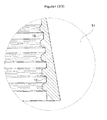
- Fig. 3
- zeigt einen Detailausschnitt von
Fig. 2 mit dem Gewinde 14. Man erkennt ein abgerundetes Trapezgewinde 14. Der erste Gewindegang 16 vom unteren Rand 36 des Mantels 28 aus ist tiefer als der letzte Gewindegang 18 vom unteren Rand 36 des Mantels 28 aus. - Im Folgenden wird kurz die Herstellung des erfindungsgemäßen Mantels 28 beschrieben. Es wird vor allem auf die erfindungswesentlichen und bevorzugten Merkmale eingegangen. Im Übrigen kann der Mantel 28 wie beispielsweise in
US 2,791,573 A oderEP 0051821 A1 beschrieben hergestellt werden. - Anders als sonst üblich bei Mänteln 28 von Isolierkannen 12 findet die Entformung aus der Pressform nicht durch Zwangsentformung statt, da ansonsten das Gewinde 14 Schaden nehmen würde. Dies wurde in Versuchen bestätigt. Die Form wird im Unterschied zum Stand der Technik um den Mantel 28 herum entfernt und anschließend wird am oberen Ende 20 in die gegenüberliegenden Ausnehmungen 22 ein Werkzeug wie beispielsweise eine in die Ausnehmungen 22 passende Stange gelegt und der Mantel 28 aus der Form herausgedreht. Dies funktioniert deshalb, da die Form im Bereich des Gewindes 14 des Mantels 28 zwangsläufig ein Gegengewinde aufweist und der ganze Mantel 28 daher aus der Form herausgeschraubt werden kann.
- Die in der vorliegenden Beschreibung, in den Zeichnungen sowie in den Ansprüchen offenbarten Merkmale der Erfindung können sowohl einzeln als auch in beliebigen Kombinationen für die Verwirklichung der Erfindung in ihren verschiedenen Ausführungsformen wesentlich sein. Die Erfindung ist nicht auf die beschriebenen Ausführungsformen beschränkt. Sie kann im Rahmen der Ansprüche und unter Berücksichtigung der Kenntnisse des zuständigen Fachmanns variiert werden.
-
- 10
- Kannenkörper
- 12
- Kanne
- 14
- Gewinde
- 16
- erster Gewindegang des Gewindes
- 18
- letzter Gewindegang des Gewindes
- 20
- oberer Rand des Mantels
- 22
- Ausnehmung
- 24
- Kopfstück mit Ausguss
- 26
- Deckel
- 28
- Mantel
- 30
- Handgriff
- 32
- Bodeneinsatz
- 34
- Dichtring
- 36
- unterer Rand des Mantels
Claims (11)
- Kannenkörper für eine Kanne (12),a. der im unteren Bereich des Kannenkörpers (10) ein Gewinde (14) aufweist, undb. wenigstens ein Teil des Kannenkörpers (10) aus einem Material besteht, das überwiegend einen Duroplast enthält.
- Kannenkörper gemäß Anspruch 1, dadurch gekennzeichnet, dass der Duroplast ein Aminoplast, besonders bevorzugt ein Harnstoffharz ist.
- Kannenkörper gemäß Anspruch 1 oder 2, dadurch gekennzeichnet, dass der Kannenkörper (10) zumindest im Bereich des Gewindes (14) aus einem Duroplast besteht.
- Kannenkörper gemäß einem der Ansprüche 1 bis 3, dadurch gekennzeichnet, dass die Gewindesteigung des Gewindes (14) in einem Bereich von 2 bis 8 mm liegt.
- Kannenkörper gemäß einem der Ansprüche 1 bis 4, dadurch gekennzeichnet, dass das Gewinde (14) ein Trapezgewinde (14), besonders bevorzugt ein gerundetes Trapezgewinde (14) ist.
- Kannenkörper gemäß einem der Ansprüche 1 bis 5, dadurch gekennzeichnet, dass die Gewindetiefe des ersten Gewindeganges (16) des Gewindes (14) von der Unterkante des Kannenkörpers (10) aus in einem Bereich von 0,4 bis 2 mm, besonders bevorzugt in einem Bereich von 0,6 bis 1 mm liegt.
- Kannenkörper gemäß einem der Ansprüche 1 bis 6, dadurch gekennzeichnet, dass die Gewindetiefe des ersten Gewindeganges (16) des Gewindes (14) von der Unterkante des Kannenkörpers (10) aus tiefer ist als die Gewindetiefe des letzten Gewindeganges (18) des Gewindes (14) von der Unterkante des Kannenkörpers (10) aus.
- Kannenkörper gemäß einem der Ansprüche 1 bis 7, dadurch gekennzeichnet, dass der Kannenkörper (10) am oberen Rand (20) zwei gegenüberliegende Ausnehmungen (22) aufweist.
- Kannenkörper gemäß einem der Ansprüche 1 bis 8, dadurch gekennzeichnet, dass die Ausnehmungen (22) eine Tiefe in einem Bereich von 2 bis 15 mm, besonders bevorzugt in einem Bereich von 6 bis 9 mm haben.
- Isolierkanne mit einem Kannenkörper (10) gemäß einem Ansprüche 1 bis 9, einem Ausguss (24) und einem Deckel (26).
- Verfahren zur Herstellung eines Kannenkörpers (10), dadurch gekennzeichnet, dass der Kannenkörper (10) bei der Entformung aus einem Gewinde (14) einer Form herausgedreht wird, die in das Gewinde (14) des Kannenkörpers (10) eingreift.
Applications Claiming Priority (1)
| Application Number | Priority Date | Filing Date | Title |
|---|---|---|---|
| DE102014105283.8A DE102014105283A1 (de) | 2014-04-14 | 2014-04-14 | Isolierkanne |
Publications (2)
| Publication Number | Publication Date |
|---|---|
| EP2932875A1 true EP2932875A1 (de) | 2015-10-21 |
| EP2932875B1 EP2932875B1 (de) | 2017-06-21 |
Family
ID=52464279
Family Applications (1)
| Application Number | Title | Priority Date | Filing Date |
|---|---|---|---|
| EP15154682.7A Not-in-force EP2932875B1 (de) | 2014-04-14 | 2015-02-11 | Isolierkanne |
Country Status (4)
| Country | Link |
|---|---|
| EP (1) | EP2932875B1 (de) |
| CN (1) | CN104970712B (de) |
| DE (1) | DE102014105283A1 (de) |
| SA (1) | SA115360450B1 (de) |
Cited By (1)
| Publication number | Priority date | Publication date | Assignee | Title |
|---|---|---|---|---|
| BE1023257B1 (nl) * | 2015-12-22 | 2017-01-12 | Allibert Hovac Nv | Glazen container voor een isolerende fles |
Citations (9)
| Publication number | Priority date | Publication date | Assignee | Title |
|---|---|---|---|---|
| GB691177A (en) * | 1949-11-08 | 1953-05-06 | Laurance Leslie Smith | Improvements in and relating to vacuum-jacketed jugs |
| US2791573A (en) | 1954-03-12 | 1957-05-07 | American Cyanamid Co | Resinous molding composition and process for producing same |
| US3311249A (en) * | 1965-08-23 | 1967-03-28 | King Seeley Thermos Co | Vacuum ware |
| EP0051821A1 (de) | 1980-11-06 | 1982-05-19 | Hüls Troisdorf Aktiengesellschaft | Verfahren zum Herstellen von dessinierten Formkörpern aus einer härtbaren Masse auf Basis duroplastischer Kunststoffe |
| DE3613293A1 (de) | 1986-02-28 | 1987-09-03 | Wulf & Co Emsa Werk | Mantel als teil einer isolierkanne |
| CN2037199U (zh) | 1988-11-08 | 1989-05-10 | 陈喜德 | 塑料真空壁保温容器 |
| CN1042518A (zh) | 1988-11-08 | 1990-05-30 | 陈喜德 | 塑料真空壁保温容器 |
| CN202497017U (zh) | 2012-03-02 | 2012-10-24 | 何立君 | 方便倒水的保温瓶胆 |
| DE202013008318U1 (de) * | 2012-09-28 | 2013-10-08 | Jie-Sen Cai | Behälter für heiße und kalte Nahrungsmittel |
Family Cites Families (7)
| Publication number | Priority date | Publication date | Assignee | Title |
|---|---|---|---|---|
| DK0840565T3 (da) * | 1995-07-26 | 2000-04-03 | Ebert Design Gmbh & Co Kg | Lukkeanordning til beholdere |
| DE29600471U1 (de) * | 1996-01-12 | 1997-05-15 | Emsa-Werke Wulf GmbH & Co, 48282 Emsdetten | Warmhaltekanne |
| DE20202025U1 (de) * | 2002-02-11 | 2003-06-26 | Emsa-Werke Wulf GmbH & Co. KG, 48282 Emsdetten | Thermokanne |
| FR2837132B1 (fr) * | 2002-03-18 | 2005-01-14 | Cebal | Procede d'obtention d'une piece en matiere plastique moulee par compression et presentant un goulot muni d'un orifice de distribution |
| CN102101343A (zh) * | 2009-12-21 | 2011-06-22 | 余定贵 | 手动式半溢式压模 |
| US8573436B2 (en) * | 2010-03-19 | 2013-11-05 | Pura Stainless Llc | Plastic-free device for fluid storage and delivery |
| CN203138159U (zh) * | 2013-02-26 | 2013-08-21 | 张昂 | 防破减震式暖水瓶 |
-
2014
- 2014-04-14 DE DE102014105283.8A patent/DE102014105283A1/de not_active Withdrawn
-
2015
- 2015-02-11 EP EP15154682.7A patent/EP2932875B1/de not_active Not-in-force
- 2015-03-06 CN CN201510101200.0A patent/CN104970712B/zh not_active Expired - Fee Related
- 2015-04-06 SA SA115360450A patent/SA115360450B1/ar unknown
Patent Citations (9)
| Publication number | Priority date | Publication date | Assignee | Title |
|---|---|---|---|---|
| GB691177A (en) * | 1949-11-08 | 1953-05-06 | Laurance Leslie Smith | Improvements in and relating to vacuum-jacketed jugs |
| US2791573A (en) | 1954-03-12 | 1957-05-07 | American Cyanamid Co | Resinous molding composition and process for producing same |
| US3311249A (en) * | 1965-08-23 | 1967-03-28 | King Seeley Thermos Co | Vacuum ware |
| EP0051821A1 (de) | 1980-11-06 | 1982-05-19 | Hüls Troisdorf Aktiengesellschaft | Verfahren zum Herstellen von dessinierten Formkörpern aus einer härtbaren Masse auf Basis duroplastischer Kunststoffe |
| DE3613293A1 (de) | 1986-02-28 | 1987-09-03 | Wulf & Co Emsa Werk | Mantel als teil einer isolierkanne |
| CN2037199U (zh) | 1988-11-08 | 1989-05-10 | 陈喜德 | 塑料真空壁保温容器 |
| CN1042518A (zh) | 1988-11-08 | 1990-05-30 | 陈喜德 | 塑料真空壁保温容器 |
| CN202497017U (zh) | 2012-03-02 | 2012-10-24 | 何立君 | 方便倒水的保温瓶胆 |
| DE202013008318U1 (de) * | 2012-09-28 | 2013-10-08 | Jie-Sen Cai | Behälter für heiße und kalte Nahrungsmittel |
Cited By (2)
| Publication number | Priority date | Publication date | Assignee | Title |
|---|---|---|---|---|
| BE1023257B1 (nl) * | 2015-12-22 | 2017-01-12 | Allibert Hovac Nv | Glazen container voor een isolerende fles |
| WO2017108769A1 (en) * | 2015-12-22 | 2017-06-29 | Allibert Hovac | Glass container for an insulating flask |
Also Published As
| Publication number | Publication date |
|---|---|
| CN104970712A (zh) | 2015-10-14 |
| SA115360450B1 (ar) | 2017-11-08 |
| CN104970712B (zh) | 2018-05-18 |
| DE102014105283A1 (de) | 2015-10-15 |
| EP2932875B1 (de) | 2017-06-21 |
Similar Documents
| Publication | Publication Date | Title |
|---|---|---|
| DE69321486T2 (de) | Spender für Kosmetika mit langlebigem Drehwiderstand | |
| EP1810593B1 (de) | Kosmetikeinheit | |
| DE1551578A1 (de) | Gefaess zum mehrmaligen Nachfuellen eines unter Druck stehenden verfluessigten Gases | |
| EP2932875B1 (de) | Isolierkanne | |
| DE1429792A1 (de) | Isolierflasche | |
| DE202011100846U1 (de) | Einfüllstutzen für einen Harnstoffbehälter und einen damit versehenen Harnstoffbehälter | |
| DE69924474T2 (de) | Mehrschichtiger Behälter und Herstellungsverfahren | |
| EP1937104B1 (de) | Cremetiegel | |
| DE7229002U (de) | Reifennagel | |
| DE69329757T2 (de) | Verbesserter Ventilaufsatz für Druckbefüllung | |
| DE202014003192U1 (de) | Vorrichtung zum Verschließen der Flaschen mit den Spirituosen | |
| CH675703A5 (de) | ||
| DE102011110548A1 (de) | Verschlussvorrichtung für einen Behälter und Verfahren zur Herstellung einer solchen Verschlussvorrichtung | |
| DE102014014110A1 (de) | Flaschenverschluss zum Verschließen einer Flasche | |
| DE1482542A1 (de) | Behaelter mit nachgiebigem oder verformbarem,aus Kunststoff bestehenden OEffnungsende | |
| DE202015006802U1 (de) | Spritzgegossener und verschweißter Kraftstofftank für Motorräder | |
| DE2132384A1 (de) | Aerosolspruehdose | |
| DE102014106116B4 (de) | Klappdeckelverschluss für eine Tube | |
| DE1919490A1 (de) | Behaelterkappe | |
| DE1812915A1 (de) | Malkasten | |
| DE956026C (de) | Behaelter fuer Tusche, Farben | |
| DE662416C (de) | Form zum Herstellen von Gegenstaenden aus Kunstharz | |
| DE7140321U (de) | Vorrichtung zum oeffnen und schliessen von mit einer schraubkappe versehenen flaschen | |
| DE824149C (de) | Verschluss fuer Flaschen und aehnliche Behaelter | |
| DE1757709A1 (de) | Servicegut,insbesondere Trinkglas |
Legal Events
| Date | Code | Title | Description |
|---|---|---|---|
| PUAI | Public reference made under article 153(3) epc to a published international application that has entered the european phase |
Free format text: ORIGINAL CODE: 0009012 |
|
| AK | Designated contracting states |
Kind code of ref document: A1 Designated state(s): AL AT BE BG CH CY CZ DE DK EE ES FI FR GB GR HR HU IE IS IT LI LT LU LV MC MK MT NL NO PL PT RO RS SE SI SK SM TR |
|
| AX | Request for extension of the european patent |
Extension state: BA ME |
|
| 17P | Request for examination filed |
Effective date: 20160323 |
|
| RBV | Designated contracting states (corrected) |
Designated state(s): AL AT BE BG CH CY CZ DE DK EE ES FI FR GB GR HR HU IE IS IT LI LT LU LV MC MK MT NL NO PL PT RO RS SE SI SK SM TR |
|
| 17Q | First examination report despatched |
Effective date: 20161125 |
|
| GRAP | Despatch of communication of intention to grant a patent |
Free format text: ORIGINAL CODE: EPIDOSNIGR1 |
|
| INTG | Intention to grant announced |
Effective date: 20170316 |
|
| GRAS | Grant fee paid |
Free format text: ORIGINAL CODE: EPIDOSNIGR3 |
|
| GRAA | (expected) grant |
Free format text: ORIGINAL CODE: 0009210 |
|
| AK | Designated contracting states |
Kind code of ref document: B1 Designated state(s): AL AT BE BG CH CY CZ DE DK EE ES FI FR GB GR HR HU IE IS IT LI LT LU LV MC MK MT NL NO PL PT RO RS SE SI SK SM TR |
|
| REG | Reference to a national code |
Ref country code: GB Ref legal event code: FG4D Free format text: NOT ENGLISH |
|
| REG | Reference to a national code |
Ref country code: CH Ref legal event code: EP |
|
| REG | Reference to a national code |
Ref country code: IE Ref legal event code: FG4D Free format text: LANGUAGE OF EP DOCUMENT: GERMAN |
|
| REG | Reference to a national code |
Ref country code: AT Ref legal event code: REF Ref document number: 902172 Country of ref document: AT Kind code of ref document: T Effective date: 20170715 |
|
| REG | Reference to a national code |
Ref country code: DE Ref legal event code: R096 Ref document number: 502015001246 Country of ref document: DE |
|
| REG | Reference to a national code |
Ref country code: NL Ref legal event code: MP Effective date: 20170621 |
|
| PG25 | Lapsed in a contracting state [announced via postgrant information from national office to epo] |
Ref country code: FI Free format text: LAPSE BECAUSE OF FAILURE TO SUBMIT A TRANSLATION OF THE DESCRIPTION OR TO PAY THE FEE WITHIN THE PRESCRIBED TIME-LIMIT Effective date: 20170621 Ref country code: LT Free format text: LAPSE BECAUSE OF FAILURE TO SUBMIT A TRANSLATION OF THE DESCRIPTION OR TO PAY THE FEE WITHIN THE PRESCRIBED TIME-LIMIT Effective date: 20170621 Ref country code: HR Free format text: LAPSE BECAUSE OF FAILURE TO SUBMIT A TRANSLATION OF THE DESCRIPTION OR TO PAY THE FEE WITHIN THE PRESCRIBED TIME-LIMIT Effective date: 20170621 Ref country code: NO Free format text: LAPSE BECAUSE OF FAILURE TO SUBMIT A TRANSLATION OF THE DESCRIPTION OR TO PAY THE FEE WITHIN THE PRESCRIBED TIME-LIMIT Effective date: 20170921 |
|
| REG | Reference to a national code |
Ref country code: LT Ref legal event code: MG4D |
|
| PG25 | Lapsed in a contracting state [announced via postgrant information from national office to epo] |
Ref country code: RS Free format text: LAPSE BECAUSE OF FAILURE TO SUBMIT A TRANSLATION OF THE DESCRIPTION OR TO PAY THE FEE WITHIN THE PRESCRIBED TIME-LIMIT Effective date: 20170621 Ref country code: NL Free format text: LAPSE BECAUSE OF FAILURE TO SUBMIT A TRANSLATION OF THE DESCRIPTION OR TO PAY THE FEE WITHIN THE PRESCRIBED TIME-LIMIT Effective date: 20170621 Ref country code: BG Free format text: LAPSE BECAUSE OF FAILURE TO SUBMIT A TRANSLATION OF THE DESCRIPTION OR TO PAY THE FEE WITHIN THE PRESCRIBED TIME-LIMIT Effective date: 20170921 Ref country code: LV Free format text: LAPSE BECAUSE OF FAILURE TO SUBMIT A TRANSLATION OF THE DESCRIPTION OR TO PAY THE FEE WITHIN THE PRESCRIBED TIME-LIMIT Effective date: 20170621 Ref country code: SE Free format text: LAPSE BECAUSE OF FAILURE TO SUBMIT A TRANSLATION OF THE DESCRIPTION OR TO PAY THE FEE WITHIN THE PRESCRIBED TIME-LIMIT Effective date: 20170621 |
|
| PG25 | Lapsed in a contracting state [announced via postgrant information from national office to epo] |
Ref country code: RO Free format text: LAPSE BECAUSE OF FAILURE TO SUBMIT A TRANSLATION OF THE DESCRIPTION OR TO PAY THE FEE WITHIN THE PRESCRIBED TIME-LIMIT Effective date: 20170621 Ref country code: CZ Free format text: LAPSE BECAUSE OF FAILURE TO SUBMIT A TRANSLATION OF THE DESCRIPTION OR TO PAY THE FEE WITHIN THE PRESCRIBED TIME-LIMIT Effective date: 20170621 Ref country code: EE Free format text: LAPSE BECAUSE OF FAILURE TO SUBMIT A TRANSLATION OF THE DESCRIPTION OR TO PAY THE FEE WITHIN THE PRESCRIBED TIME-LIMIT Effective date: 20170621 Ref country code: SK Free format text: LAPSE BECAUSE OF FAILURE TO SUBMIT A TRANSLATION OF THE DESCRIPTION OR TO PAY THE FEE WITHIN THE PRESCRIBED TIME-LIMIT Effective date: 20170621 |
|
| PG25 | Lapsed in a contracting state [announced via postgrant information from national office to epo] |
Ref country code: SM Free format text: LAPSE BECAUSE OF FAILURE TO SUBMIT A TRANSLATION OF THE DESCRIPTION OR TO PAY THE FEE WITHIN THE PRESCRIBED TIME-LIMIT Effective date: 20170621 Ref country code: ES Free format text: LAPSE BECAUSE OF FAILURE TO SUBMIT A TRANSLATION OF THE DESCRIPTION OR TO PAY THE FEE WITHIN THE PRESCRIBED TIME-LIMIT Effective date: 20170621 Ref country code: IS Free format text: LAPSE BECAUSE OF FAILURE TO SUBMIT A TRANSLATION OF THE DESCRIPTION OR TO PAY THE FEE WITHIN THE PRESCRIBED TIME-LIMIT Effective date: 20171021 Ref country code: IT Free format text: LAPSE BECAUSE OF FAILURE TO SUBMIT A TRANSLATION OF THE DESCRIPTION OR TO PAY THE FEE WITHIN THE PRESCRIBED TIME-LIMIT Effective date: 20170621 Ref country code: PL Free format text: LAPSE BECAUSE OF FAILURE TO SUBMIT A TRANSLATION OF THE DESCRIPTION OR TO PAY THE FEE WITHIN THE PRESCRIBED TIME-LIMIT Effective date: 20170621 |
|
| REG | Reference to a national code |
Ref country code: DE Ref legal event code: R097 Ref document number: 502015001246 Country of ref document: DE |
|
| PLBE | No opposition filed within time limit |
Free format text: ORIGINAL CODE: 0009261 |
|
| STAA | Information on the status of an ep patent application or granted ep patent |
Free format text: STATUS: NO OPPOSITION FILED WITHIN TIME LIMIT |
|
| PG25 | Lapsed in a contracting state [announced via postgrant information from national office to epo] |
Ref country code: DK Free format text: LAPSE BECAUSE OF FAILURE TO SUBMIT A TRANSLATION OF THE DESCRIPTION OR TO PAY THE FEE WITHIN THE PRESCRIBED TIME-LIMIT Effective date: 20170621 |
|
| 26N | No opposition filed |
Effective date: 20180322 |
|
| PG25 | Lapsed in a contracting state [announced via postgrant information from national office to epo] |
Ref country code: SI Free format text: LAPSE BECAUSE OF FAILURE TO SUBMIT A TRANSLATION OF THE DESCRIPTION OR TO PAY THE FEE WITHIN THE PRESCRIBED TIME-LIMIT Effective date: 20170621 |
|
| REG | Reference to a national code |
Ref country code: CH Ref legal event code: PL |
|
| PG25 | Lapsed in a contracting state [announced via postgrant information from national office to epo] |
Ref country code: MT Free format text: LAPSE BECAUSE OF FAILURE TO SUBMIT A TRANSLATION OF THE DESCRIPTION OR TO PAY THE FEE WITHIN THE PRESCRIBED TIME-LIMIT Effective date: 20170621 Ref country code: MC Free format text: LAPSE BECAUSE OF FAILURE TO SUBMIT A TRANSLATION OF THE DESCRIPTION OR TO PAY THE FEE WITHIN THE PRESCRIBED TIME-LIMIT Effective date: 20170621 |
|
| REG | Reference to a national code |
Ref country code: IE Ref legal event code: MM4A |
|
| REG | Reference to a national code |
Ref country code: BE Ref legal event code: MM Effective date: 20180228 |
|
| PG25 | Lapsed in a contracting state [announced via postgrant information from national office to epo] |
Ref country code: CH Free format text: LAPSE BECAUSE OF NON-PAYMENT OF DUE FEES Effective date: 20180228 Ref country code: LI Free format text: LAPSE BECAUSE OF NON-PAYMENT OF DUE FEES Effective date: 20180228 Ref country code: LU Free format text: LAPSE BECAUSE OF NON-PAYMENT OF DUE FEES Effective date: 20180211 |
|
| REG | Reference to a national code |
Ref country code: FR Ref legal event code: ST Effective date: 20181031 |
|
| PG25 | Lapsed in a contracting state [announced via postgrant information from national office to epo] |
Ref country code: IE Free format text: LAPSE BECAUSE OF NON-PAYMENT OF DUE FEES Effective date: 20180211 |
|
| PG25 | Lapsed in a contracting state [announced via postgrant information from national office to epo] |
Ref country code: FR Free format text: LAPSE BECAUSE OF NON-PAYMENT OF DUE FEES Effective date: 20180228 Ref country code: BE Free format text: LAPSE BECAUSE OF NON-PAYMENT OF DUE FEES Effective date: 20180228 |
|
| PGFP | Annual fee paid to national office [announced via postgrant information from national office to epo] |
Ref country code: DE Payment date: 20190211 Year of fee payment: 5 |
|
| GBPC | Gb: european patent ceased through non-payment of renewal fee |
Effective date: 20190211 |
|
| PG25 | Lapsed in a contracting state [announced via postgrant information from national office to epo] |
Ref country code: GB Free format text: LAPSE BECAUSE OF NON-PAYMENT OF DUE FEES Effective date: 20190211 |
|
| PG25 | Lapsed in a contracting state [announced via postgrant information from national office to epo] |
Ref country code: TR Free format text: LAPSE BECAUSE OF FAILURE TO SUBMIT A TRANSLATION OF THE DESCRIPTION OR TO PAY THE FEE WITHIN THE PRESCRIBED TIME-LIMIT Effective date: 20170621 |
|
| PG25 | Lapsed in a contracting state [announced via postgrant information from national office to epo] |
Ref country code: PT Free format text: LAPSE BECAUSE OF FAILURE TO SUBMIT A TRANSLATION OF THE DESCRIPTION OR TO PAY THE FEE WITHIN THE PRESCRIBED TIME-LIMIT Effective date: 20170621 |
|
| PG25 | Lapsed in a contracting state [announced via postgrant information from national office to epo] |
Ref country code: CY Free format text: LAPSE BECAUSE OF FAILURE TO SUBMIT A TRANSLATION OF THE DESCRIPTION OR TO PAY THE FEE WITHIN THE PRESCRIBED TIME-LIMIT Effective date: 20170621 Ref country code: MK Free format text: LAPSE BECAUSE OF NON-PAYMENT OF DUE FEES Effective date: 20170621 Ref country code: HU Free format text: LAPSE BECAUSE OF FAILURE TO SUBMIT A TRANSLATION OF THE DESCRIPTION OR TO PAY THE FEE WITHIN THE PRESCRIBED TIME-LIMIT; INVALID AB INITIO Effective date: 20150211 Ref country code: GR Free format text: LAPSE BECAUSE OF FAILURE TO SUBMIT A TRANSLATION OF THE DESCRIPTION OR TO PAY THE FEE WITHIN THE PRESCRIBED TIME-LIMIT Effective date: 20170621 |
|
| PG25 | Lapsed in a contracting state [announced via postgrant information from national office to epo] |
Ref country code: AL Free format text: LAPSE BECAUSE OF FAILURE TO SUBMIT A TRANSLATION OF THE DESCRIPTION OR TO PAY THE FEE WITHIN THE PRESCRIBED TIME-LIMIT Effective date: 20170621 |
|
| REG | Reference to a national code |
Ref country code: DE Ref legal event code: R119 Ref document number: 502015001246 Country of ref document: DE |
|
| PG25 | Lapsed in a contracting state [announced via postgrant information from national office to epo] |
Ref country code: DE Free format text: LAPSE BECAUSE OF NON-PAYMENT OF DUE FEES Effective date: 20200901 |
|
| REG | Reference to a national code |
Ref country code: AT Ref legal event code: MM01 Ref document number: 902172 Country of ref document: AT Kind code of ref document: T Effective date: 20200211 |
|
| PG25 | Lapsed in a contracting state [announced via postgrant information from national office to epo] |
Ref country code: AT Free format text: LAPSE BECAUSE OF NON-PAYMENT OF DUE FEES Effective date: 20200211 |