EP2932873A1 - Sac d'égouttage - Google Patents
Sac d'égouttage Download PDFInfo
- Publication number
- EP2932873A1 EP2932873A1 EP13863336.7A EP13863336A EP2932873A1 EP 2932873 A1 EP2932873 A1 EP 2932873A1 EP 13863336 A EP13863336 A EP 13863336A EP 2932873 A1 EP2932873 A1 EP 2932873A1
- Authority
- EP
- European Patent Office
- Prior art keywords
- bag body
- oblique folding
- folding lines
- center line
- center
- Prior art date
- Legal status (The legal status is an assumption and is not a legal conclusion. Google has not performed a legal analysis and makes no representation as to the accuracy of the status listed.)
- Granted
Links
- 239000000463 material Substances 0.000 claims abstract description 18
- XLYOFNOQVPJJNP-UHFFFAOYSA-N water Substances O XLYOFNOQVPJJNP-UHFFFAOYSA-N 0.000 claims abstract description 18
- 238000001914 filtration Methods 0.000 claims abstract description 14
- 238000000926 separation method Methods 0.000 claims description 9
- 238000000605 extraction Methods 0.000 claims description 8
- 239000000835 fiber Substances 0.000 description 10
- 240000007154 Coffea arabica Species 0.000 description 9
- 235000016213 coffee Nutrition 0.000 description 9
- 235000013353 coffee beverage Nutrition 0.000 description 9
- 238000000034 method Methods 0.000 description 8
- 244000269722 Thea sinensis Species 0.000 description 5
- -1 polyethylene Polymers 0.000 description 5
- 238000004519 manufacturing process Methods 0.000 description 4
- 230000015572 biosynthetic process Effects 0.000 description 3
- 238000005520 cutting process Methods 0.000 description 3
- 230000000694 effects Effects 0.000 description 3
- 235000013616 tea Nutrition 0.000 description 3
- 239000004743 Polypropylene Substances 0.000 description 2
- 235000009569 green tea Nutrition 0.000 description 2
- 241000411851 herbal medicine Species 0.000 description 2
- 230000002209 hydrophobic effect Effects 0.000 description 2
- 229920001155 polypropylene Polymers 0.000 description 2
- 239000000843 powder Substances 0.000 description 2
- 239000002994 raw material Substances 0.000 description 2
- 230000002787 reinforcement Effects 0.000 description 2
- 238000003466 welding Methods 0.000 description 2
- 241001265525 Edgeworthia chrysantha Species 0.000 description 1
- 240000000249 Morus alba Species 0.000 description 1
- 235000008708 Morus alba Nutrition 0.000 description 1
- 240000000907 Musa textilis Species 0.000 description 1
- 239000004677 Nylon Substances 0.000 description 1
- 239000004698 Polyethylene Substances 0.000 description 1
- 229920001131 Pulp (paper) Polymers 0.000 description 1
- 229920000297 Rayon Polymers 0.000 description 1
- 229920002978 Vinylon Polymers 0.000 description 1
- 239000002131 composite material Substances 0.000 description 1
- 239000002657 fibrous material Substances 0.000 description 1
- 239000004745 nonwoven fabric Substances 0.000 description 1
- 229920001778 nylon Polymers 0.000 description 1
- 239000002985 plastic film Substances 0.000 description 1
- 229920000747 poly(lactic acid) Polymers 0.000 description 1
- 229920002961 polybutylene succinate Polymers 0.000 description 1
- 239000004631 polybutylene succinate Substances 0.000 description 1
- 229920000728 polyester Polymers 0.000 description 1
- 229920000573 polyethylene Polymers 0.000 description 1
- 239000004626 polylactic acid Substances 0.000 description 1
- 238000004080 punching Methods 0.000 description 1
- 239000002964 rayon Substances 0.000 description 1
- 238000007789 sealing Methods 0.000 description 1
- 238000010025 steaming Methods 0.000 description 1
- 229920002994 synthetic fiber Polymers 0.000 description 1
- 239000012209 synthetic fiber Substances 0.000 description 1
- 238000002604 ultrasonography Methods 0.000 description 1
- 239000002759 woven fabric Substances 0.000 description 1
Images


Classifications
-
- A—HUMAN NECESSITIES
- A47—FURNITURE; DOMESTIC ARTICLES OR APPLIANCES; COFFEE MILLS; SPICE MILLS; SUCTION CLEANERS IN GENERAL
- A47J—KITCHEN EQUIPMENT; COFFEE MILLS; SPICE MILLS; APPARATUS FOR MAKING BEVERAGES
- A47J31/00—Apparatus for making beverages
- A47J31/06—Filters or strainers for coffee or tea makers ; Holders therefor
-
- B—PERFORMING OPERATIONS; TRANSPORTING
- B65—CONVEYING; PACKING; STORING; HANDLING THIN OR FILAMENTARY MATERIAL
- B65D—CONTAINERS FOR STORAGE OR TRANSPORT OF ARTICLES OR MATERIALS, e.g. BAGS, BARRELS, BOTTLES, BOXES, CANS, CARTONS, CRATES, DRUMS, JARS, TANKS, HOPPERS, FORWARDING CONTAINERS; ACCESSORIES, CLOSURES, OR FITTINGS THEREFOR; PACKAGING ELEMENTS; PACKAGES
- B65D85/00—Containers, packaging elements or packages, specially adapted for particular articles or materials
- B65D85/70—Containers, packaging elements or packages, specially adapted for particular articles or materials for materials not otherwise provided for
- B65D85/804—Disposable containers or packages with contents which are mixed, infused or dissolved in situ, i.e. without having been previously removed from the package
- B65D85/8043—Packages adapted to allow liquid to pass through the contents
- B65D85/8061—Filters
-
- A—HUMAN NECESSITIES
- A47—FURNITURE; DOMESTIC ARTICLES OR APPLIANCES; COFFEE MILLS; SPICE MILLS; SUCTION CLEANERS IN GENERAL
- A47J—KITCHEN EQUIPMENT; COFFEE MILLS; SPICE MILLS; APPARATUS FOR MAKING BEVERAGES
- A47J31/00—Apparatus for making beverages
- A47J31/02—Coffee-making machines with removable extraction cups, to be placed on top of drinking-vessels i.e. coffee-makers with removable brewing vessels, to be placed on top of beverage containers, into which hot water is poured, e.g. cafe filter
-
- A—HUMAN NECESSITIES
- A47—FURNITURE; DOMESTIC ARTICLES OR APPLIANCES; COFFEE MILLS; SPICE MILLS; SUCTION CLEANERS IN GENERAL
- A47J—KITCHEN EQUIPMENT; COFFEE MILLS; SPICE MILLS; APPARATUS FOR MAKING BEVERAGES
- A47J31/00—Apparatus for making beverages
- A47J31/06—Filters or strainers for coffee or tea makers ; Holders therefor
- A47J31/0605—Filters or strainers for coffee or tea makers ; Holders therefor with a valve at the filter-outlet; Anti-drip devices
-
- A—HUMAN NECESSITIES
- A47—FURNITURE; DOMESTIC ARTICLES OR APPLIANCES; COFFEE MILLS; SPICE MILLS; SUCTION CLEANERS IN GENERAL
- A47J—KITCHEN EQUIPMENT; COFFEE MILLS; SPICE MILLS; APPARATUS FOR MAKING BEVERAGES
- A47J31/00—Apparatus for making beverages
- A47J31/06—Filters or strainers for coffee or tea makers ; Holders therefor
- A47J31/0626—Filters or strainers for coffee or tea makers ; Holders therefor with means for securing the filter holder to the beverage container
-
- A—HUMAN NECESSITIES
- A47—FURNITURE; DOMESTIC ARTICLES OR APPLIANCES; COFFEE MILLS; SPICE MILLS; SUCTION CLEANERS IN GENERAL
- A47J—KITCHEN EQUIPMENT; COFFEE MILLS; SPICE MILLS; APPARATUS FOR MAKING BEVERAGES
- A47J31/00—Apparatus for making beverages
- A47J31/06—Filters or strainers for coffee or tea makers ; Holders therefor
- A47J31/0636—Filters or strainers for coffee or tea makers ; Holders therefor suspended from the top of the beverage container so as to remain in contact with the prepared infusion
Definitions
- the present invention relates to a drip bag which is hooked on the upper portion of a container such as cups, thereby allowing an extract such as coffee, tea, green tea, or Chinese herbal medicine to be readily provided by a drip method.
- the paper drip method has been widely accepted as a coffee serving method that enables one to enjoy genuine coffee in an easy-to-prepare manner.
- This paper drip method typically allows several cups of coffee to be extracted at a time.
- the drip bag in a simple structure that can be manufactured at low costs.
- the drip bag has a bag body made of a water permeable filtering sheet and paper plate hook members that are adhered to the outer surfaces of the two opposing face sheets of the bag body, with the hook members formed in a special shape (Patent Literature 1).
- hook parts 11X of hook members 10X are pulled out from a bag body 2 so as to hook the hook parts 11X on a cup 200. This allows the drip bag 1X to be easily set to the cup 200 with the opening 3 of the bag body 2 kept open.
- Patent Literature 1 Japanese Patent No. 4079041
- the drip bag 1X mentioned above allows the opening 3 of the bag body 2 to be widely opened in a rectangular shape as shown in Fig. 9 , so that hot water can be easily poured into the bag body 2.
- the opening area of the opening is desirably further increased.
- the difference in rigidity between the water permeable filtering sheet forming the bag body 2 and the thin plate-shaped material forming the hook members 10X should be satisfied.
- an object of the present invention is to provide a drip bag which has a simple structure with the hook members adhered to the outer surfaces of the two opposing face sheets of the bag body and in which when the drip bag is set to a cup, the opening area of the opening of the bag body is significantly increased.
- the inventor has found the following feature and thus completed the present invention.
- the feature is provided by a drip bag with a simple structure in which hook members are adhered to the outer surfaces of two opposing face sheets of a bag body, the drip bag being configured such that a plurality of folding lines are formed on an upper stuck part adhered along the opening of the bag body so that the opening can be opened in the shape of a polygon having eight or more corners; the folding lines are obliquely oriented relative to the upper side of the upper stuck part; and furthermore, a special relation is imparted to the oblique angles between the plurality of folding lines.
- This feature allows the opening to be readily opened in the shape of a polygon having eight corners or more only by pulling, in the opposite directions, the hook members on the two opposing face sheets of the bag body.
- the present invention provides a drip bag which has a bag body formed of a water permeable filtering sheet and having an upper end to be opened, and hook members formed of a thin plate-shaped material and provided on outer surfaces of two opposing face sheets of the bag body.
- the hook member includes: an upper stuck part which is adhered to the bag body along the opening of the bag body; a center part which is located below the upper stuck part at the center of the bag body in the width direction thereof and formed so as not to be pulled out from the bag body; and a hook part not adhered to the bag body.
- Two or more pairs of oblique folding lines are formed on the upper stuck part with a center line disposed between the oblique folding lines of each pair and tilted so as to be more spaced apart from the center line in the direction from the lower side to the upper side of the upper stuck part, the center line bisecting the bag body in the width direction thereof.
- the drip bag is configured such that an angle ⁇ 1 formed by the center line and a first one of the oblique folding lines closer to the center line and an angle ⁇ 2 formed by the center line and a second oblique folding line that is farther away from the center line than the first oblique folding line satisfy 0 ⁇ ⁇ 2 ⁇ ⁇ 1.
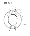
- the drip bag of the present invention when the pair of opposing hook parts on the outer surfaces of the bag body are pulled out in the opposite directions and then hooked on a cup, two or more pairs of oblique folding lines formed on the upper stuck part along the opening of the bag body allow the opening of the bag body to be opened in the shape of a polygon having eight or more corners, preferably in a generally regular decagon.
- the opening area can be significantly increased.
- this allows the opening area of the opening to be increased by about 23% when compared with a conventional drip bag having a bag body of which opening is opened in a rectangular shape even when a stuck member and a bag body of the same raw material, shape, and size as those of the conventional drip bag are used.
- the ease of use of the drip bag is improved, for example, hot water can be poured more easily through the opening of the drip bag.
- Fig. 1 is a plan view illustrating a drip bag 1 before being opened according to an embodiment of the present invention.
- the drip bag 1 has a bag body 2 with two opposing surfaces, and hook members 10 which are provided on outer surfaces of the two opposing face sheets of the bag body 2.
- the bag body 2 is formed of a water permeable filtering sheet in the shape of a flat bag which is rectangular when viewed from above, and is provided with an opening guide line 4 such as perforations for forming an opening on the upper end.
- the bag body 2 is filled with a material to be extracted such as coffee, tea, green tea, or Chinese herbal medicine.
- Fig. 2 is a perspective view illustrating the state in which the upper end of the drip bag 1 is removed and opened to form an opening 3 along the opening guide line 4, and then hook parts 11 of the hook members 10 are being pulled out from the bag body 2.
- the hook members 10 of the drip bag 1 are formed by punching a thin plate-shaped material such as a paper plate or a plastic sheet and then adhered to the bag body 2.
- the areas shaded by dots are formed in such a manner that part or the entirety of the hook member 10 on the shaded areas is adhered to the outer surface of the bag body 2 by heat sealing or adhesion and thus cannot be pulled off from the surface of the bag body 2.
- the drip bag of the present invention is provided with two opposing face sheets on the bag body, and provided on each of the surfaces is the hook member 10 including: an upper stuck part to be adhered to the bag body 2 along the opening 3 of the bag body 2; a center part which is located below the upper stuck part at the center in the width direction of the bag body 2 and formed so as not to be pulled out from the bag body 2; and the hook part 11 which is not adhered to the bag body 2.
- the drip bag 1 of this embodiment is configured such that the hook member 10 has, as the upper stuck part, an elongated stuck part 12 that is adhered in the shape of a strip to the bag body 2 along the opening 3; and as the center part, a center stuck part 13 that is adhered to the center of the bag body 2.
- the drip bag 1 has arm parts 14 that are formed to be capable of being pulled out from the bag body 2.
- the center stuck part 13 is formed in the shape of a concave with the entire surface thereof adhered to the bag body.
- the arm part 14 is located above the center stuck part 13, and the lower end of the arm part 14 is continuous with the recessed portion of the concave of the center stuck part 13. Thus, the arm part 14 is pulled out at the upper end thereof.
- the hook part 11 is formed to surround the center stuck part 13 and the arm part 14, and the upper portion of the hook part 11 is continuous with the upper end of the arm part 14. Furthermore, the hook part 11 is provided, on both sides of the upper portion thereof, with a pair of hooks 15 extending generally in the horizontal direction, and with folding lines Lx formed in the vertical direction at side ends of the center part on the bag body.
- a reinforcement part 16 which extends along the outer side of the hook part 11 in the vertical direction from both the right and left ends of the elongated stuck part 12 and which is adhered to the bag body 2.
- the drip bag 1 is configured such that a total of two pairs, i.e., a pair of first oblique folding lines L1 and a pair of second oblique folding lines L2 are formed side by side on the elongated stuck part 12, the oblique folding lines of each pair being arranged with a center line Z therebetween and tilted so as to be more spaced apart from the center line Z in the direction from the lower side 12b to the upper side 12a of the elongated stuck part 12, the center line Z bisecting the bag body 2 in the width direction.
- the drip bag 1 is also characterized in that the relation, 0 ⁇ ⁇ 2 ⁇ ⁇ 1, is satisfied where the angle ⁇ 1 is formed by the center line Z and the first oblique folding line L1 closer to the center line Z, and the angle ⁇ 2 is formed by the center line Z and the second oblique folding line L2 that is farther away from the center line Z than the first oblique folding line L1 is.
- This arrangement allows both the first oblique folding lines L1 and the second oblique folding lines L2 to be folded and the opening 3 of the bag body 2 to be opened to form a polygon with eight corners or more only by opening the drip bag 1 and then pulling, in the opposite directions, the hook parts 11 of the pair of hook members 10 adhered to the opposing face sheets of the bag body 2.
- pulling the pair of hook parts 11 in the opposite directions would cause the first oblique folding lines L1 closer to the center line Z to be naturally folded, but the second oblique folding lines L2 farther away from the center line Z to be less prone to being folded.
- the opening 3 is more likely to be opened in the shape of a flat rectangle.
- the second oblique folding lines L2 are farther away from the center line Z than the first oblique folding lines L1 closer to the center line Z, and thus folded less easily than the first oblique folding lines L1.
- the relation, ⁇ 2 ⁇ ⁇ 1 is established so that the second oblique folding lines L2 are more easily folded than the first oblique folding lines in terms of the magnitude of the angle.
- This relation allows not only the first oblique folding lines L1 closer to the center line Z but also the second oblique folding lines L2 farther away from the center line Z than the first oblique folding lines L1 to be naturally folded only by pulling the pair of hook parts 11 in the opposite directions.
- the second oblique folding line L2 and the center line Z may form an angle of zero, that is, the second folding line may be formed to be perpendicular to the upper side 12a of the upper stuck part 12. This is not preferable because when the pair of hook parts 11 are pulled in the opposite directions, only the second folding lines are folded without the first oblique folding lines L1 being folded.
- the oblique folding lines and the center line may form a negative angle, that is, the oblique folding lines may be tilted so as to approach the center line Z of the width of the bag body 2 in a direction from the lower side 12b to the upper side 12a of the upper stuck part 12. This is not preferable because this will lead to a twist with the opening 3 of the bag body 2, causing the opening 3 not to be fully opened.
- all the oblique folding lines may be defined so as to satisfy the relation, 0 ⁇ ⁇ n ⁇ ⁇ n-1 (for n ⁇ 2), where ⁇ n is the angle formed by the center line Z and the nth oblique folding line from the center line Z, and ⁇ n-1 is the angle formed by the center line Z and the (n-1)th oblique folding line from the center line Z.
- ⁇ n is the angle formed by the center line Z and the (n-1)th oblique folding line from the center line Z.
- the drip bag 1 is also configured such that the first oblique folding lines L1 and the second oblique folding lines L2 are formed to be easily folded so that these folding lines can be folded only by pulling the pair of hook parts 11 in the opposite directions.
- the ties are preferably made as short as possible and the number of the ties is made as small as possible.
- These folding lines may also be formed only as cutting lines. Taking into account the workability of adhering the hook members 10 to the water permeable filtering sheet that forms the bag body 2, two ties or less would be preferably provided.
- the first oblique folding lines L1 and the second oblique folding lines L2 are creased so that the lines are easily folded, and may also be formed by being cut halfway therethrough.
- the separation w1 on the upper side 12a of the upper stuck part 12 between the pair of first oblique folding lines L1 may be made equal to the separation w2 on the upper side 12a of the upper stuck part 12 between the first oblique folding line L1 and the second oblique folding line L2 which are adjacent to each other.
- the opening of the drip bag 1 can be preferably opened in the shape of a generally regular decagon as shown in Fig. 3B .
- the water permeable filtering sheet 20 for forming the bag body 2 various types of sheets may be used which allow a predetermined amount of extraction material to effuse when the extraction material is charged into the bag body and hot water is poured therein.
- the effusion sheet are, for example, synthetic fiber such as polyester, nylon, polyethylene, polypropylene, or vinylon; semisynthetic fiber such as rayon; woven fabric or nonwoven fabric of single or composite fiber of natural fiber such as mulberry and mitsumata plant; mixed paper of Manila hemp, wood pulp, polypropylene fiber or the like; and papers such as tea bag base paper. These can also be used for the present invention.
- unbleached fiber may be used to form the water permeable filtering sheet 20, and unbleached thin plate-shaped material may be used to form the hook member 10. Furthermore, from the viewpoint of disposal of drip bags after use, it is preferable for the water permeable filtering sheet material and the thin plate-shaped material to contain biodegradable fiber.
- Biodegradable fibers may include polylactic acid, polybutylene succinate, and polyethylene succinate.
- an extract material such as coffee powder
- moderate steaming effects can be preferably imparted to the extraction material when being dripped.
- a dense and non-dense multi-layer structure in which the voidage of the fiber layers can be adjusted to make a layer directly in contact with the extraction material "non-dense," whereas the layer not directly in contact therewith is made "dense.”
- the upper end of the bag body 2 is first cut away along the opening guide line 4 such as perforations to thereby open the bag body 2. Then, as shown in Fig. 2 , the arm parts 14 and the hook parts 11 of the pair of hook members 10 on the front and rear face sheets of the bag body 2 are pulled out and then further pulled out to hook the hook parts 11 on the cup 200 as shown in Fig. 3A .
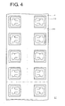
- a method for manufacturing the drip bag of the present invention includes, for example as shown in Fig. 4 , a step of preparing a drip bag sheet 21 with elongated water permeable filtering sheets 20 on which a plurality of pairs of hook members 10 are arranged at predetermined intervals so that the bottoms in each pair are spaced apart from and opposed to each other.
- the method further includes the steps of: folding the sheet 21 into two so that the edge sides in the longitudinal direction overlap with each other; and repeatedly welding and cutting the bag body 2 in the transverse direction at intervals of the width thereof while an extraction material such as coffee powder is charged into the bag body one by one.
- the portions welded and cut as mentioned above are both the side edges 2p and 2q of the bag body 2 ( Fig. 1 ).
- the water permeable filtering sheet 21 is provided in advance with the opening guide line 4 such as perforations as an opening line for ease of opening.
- the perforations 4 as the opening guide line 4 may be replaced by a line-shaped fragile portion that is provided, for example, by ultrasound or heat.
- the drip bag of the present invention can be implemented in various aspects.
- the oblique folding lines provided on the upper stuck part it is also acceptable to form three or more pairs of oblique folding lines with the center line Z disposed between the oblique folding lines of each pair, the center line Z bisecting the bag body 2 in the direction of the width thereof.
- the opening shape of the drip bag can be made closer to the shape of a perfect circle.
- two or three pairs of oblique folding lines are preferable as the number of oblique folding lines.
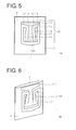
- the center stuck part 13 may be formed in the shape of a kanji character " ", and then the center stuck part 13 is made continuous with the upper stuck part 12 so that the arm part 14 is partitioned into right and left parts.
- the drip bag 1B is also configured such that a pair of first oblique folding lines L1 and a pair of second oblique folding lines L2 are formed with the center line Z disposed between the oblique folding lines of each pair, the center line Z bisecting the bag body 2 in the direction of the width thereof, and these lines are formed at angles that satisfy the relation of 0 ⁇ ⁇ 2 ⁇ ⁇ 1.
- the opening 3 of the drip bag 1B only by opening the opening 3 as shown in Fig. 6 , pulling out the pair of hook parts 11 in the opposite directions, and then hooking the hook parts on a cup.
- Fig. 7 shows a drip bag 1C which is shaped as a laterally elongated flat bag as compared with the drip bag 1 shown in Fig. 1 that has the bag body 2 shaped as a vertically elongated flat bag in a plan view.
- the hook members 10 are also laterally elongated.
- the drip bag 1C has an elongated upper stuck part 12 along the opening 3 of the bag body 2, and the lower portion of the upper stuck part 12 at the center in the width direction thereof is continuous with a center part 13 that cannot be pulled out.
- the upper stuck part 12 is provided with a pair of first oblique folding lines L1 and a pair of second oblique folding lines L2 which are directed from the lower side to the upper side of the upper stuck part 12.
- the center part 13 is not adhered to the bag body 2, but may also be adhered thereto to employ the center part 13 as a center stuck part.
- the arm part 14 extends horizontally from the lower end of the center part 13 to the right and left directions, and the ends of an arc-shaped hook part 11 are connected to the right and left ends of the arm part 14.
- the hook parts 11 are pulled out in the mutually opposite directions so as to hook the hook parts 11 to the cup 200 as shown in Fig. 8 .
- This causes all of the first oblique folding lines L1 and the second oblique folding lines L2 of the upper stuck part 12 to be folded and the opening 3 of the bag body 2 to be opened in a polygon with eight corners or more. It is thus possible to obtain a wide opening area.
Landscapes
- Engineering & Computer Science (AREA)
- Food Science & Technology (AREA)
- Mechanical Engineering (AREA)
- Apparatus For Making Beverages (AREA)
- Packages (AREA)
Applications Claiming Priority (2)
| Application Number | Priority Date | Filing Date | Title |
|---|---|---|---|
| PCT/JP2012/082113 WO2014091568A1 (fr) | 2012-12-11 | 2012-12-11 | Sac de filtrage |
| PCT/JP2013/083260 WO2014092136A1 (fr) | 2012-12-11 | 2013-12-11 | Sac d'égouttage |
Publications (3)
| Publication Number | Publication Date |
|---|---|
| EP2932873A1 true EP2932873A1 (fr) | 2015-10-21 |
| EP2932873A4 EP2932873A4 (fr) | 2016-08-03 |
| EP2932873B1 EP2932873B1 (fr) | 2017-05-17 |
Family
ID=50933892
Family Applications (1)
| Application Number | Title | Priority Date | Filing Date |
|---|---|---|---|
| EP13863336.7A Active EP2932873B1 (fr) | 2012-12-11 | 2013-12-11 | Sac d'égouttage |
Country Status (7)
| Country | Link |
|---|---|
| US (1) | US10730692B2 (fr) |
| EP (1) | EP2932873B1 (fr) |
| KR (1) | KR101639508B1 (fr) |
| CN (1) | CN104334060B (fr) |
| RU (1) | RU2638508C2 (fr) |
| TW (1) | TWI557044B (fr) |
| WO (2) | WO2014091568A1 (fr) |
Cited By (1)
| Publication number | Priority date | Publication date | Assignee | Title |
|---|---|---|---|---|
| WO2018193295A1 (fr) * | 2017-04-21 | 2018-10-25 | Castillo Redondo Mauricio | Dispositif d'infusion portable |
Families Citing this family (17)
| Publication number | Priority date | Publication date | Assignee | Title |
|---|---|---|---|---|
| KR20170002452U (ko) | 2015-12-29 | 2017-07-07 | 주식회사 영우워터라인 | 저렴한 단가로 용이하게 제조되는 커피추출을 위한 일회용 접이식 드립퍼 |
| KR20170002637U (ko) | 2016-01-14 | 2017-07-24 | 주식회사 영우워터라인 | 컵의 장착이 용이한 일회용 드립퍼 |
| CN107963345B (zh) * | 2017-07-14 | 2019-11-26 | 常州信息职业技术学院 | 悬挂式粉末饮品包装袋 |
| US10624487B2 (en) * | 2017-09-28 | 2020-04-21 | Tzu-Chi LIN | Anti-overflow brewing filter and spiral hanging-ear structure coupled thereto |
| CN109645822A (zh) * | 2017-10-11 | 2019-04-19 | 林紫绮 | 防溢漏冲泡过滤器及螺旋挂耳结构 |
| TWI721240B (zh) * | 2018-01-08 | 2021-03-11 | 林紫綺 | 掛耳式杯套結構 |
| DE102018101333A1 (de) * | 2018-01-22 | 2019-07-25 | Melitta Single Portions Gmbh & Co. Kg | Portionspackung und Verfahren zur Herstellung eines Getränks |
| DE102018101338A1 (de) * | 2018-01-22 | 2019-07-25 | Melitta Single Portions Gmbh & Co. Kg | Verfahren zur Herstellung eines Getränks mit einer Portionspackung und Portionspackung |
| JP7148907B2 (ja) * | 2018-04-20 | 2022-10-06 | キーコーヒー株式会社 | ドリップバッグ |
| JP7250278B2 (ja) * | 2018-08-10 | 2023-04-03 | 味の素株式会社 | ドリップバッグ |
| JP6710385B1 (ja) * | 2019-09-03 | 2020-06-17 | キーコーヒー株式会社 | 抽出バッグ |
| CN115135206B (zh) * | 2020-02-26 | 2024-05-28 | 大纪商事株式会社 | 滴滤袋 |
| JP7452859B2 (ja) | 2020-12-03 | 2024-03-19 | 大紀商事株式会社 | ドリップバッグ |
| KR102368513B1 (ko) * | 2021-06-03 | 2022-02-25 | 주찬 | 음료 추출용 드립 백 |
| KR102368514B1 (ko) * | 2021-06-03 | 2022-02-25 | 주찬 | 이중 고정이 가능한 음료 추출용 드립 백 |
| CN117677323A (zh) * | 2021-07-21 | 2024-03-08 | 大纪商事株式会社 | 滴滤袋 |
| US11694876B2 (en) | 2021-12-08 | 2023-07-04 | Applied Materials, Inc. | Apparatus and method for delivering a plurality of waveform signals during plasma processing |
Citations (3)
| Publication number | Priority date | Publication date | Assignee | Title |
|---|---|---|---|---|
| JP2004242847A (ja) * | 2003-02-13 | 2004-09-02 | Fuso Sangyo Kk | ドリップバッグ |
| EP2281492A1 (fr) * | 2008-05-26 | 2011-02-09 | Ohki Co., Ltd. | Sachet-filtre |
| CN102670075A (zh) * | 2011-03-15 | 2012-09-19 | 不双产业株式会社 | 滴滤袋 |
Family Cites Families (23)
| Publication number | Priority date | Publication date | Assignee | Title |
|---|---|---|---|---|
| US2859878A (en) * | 1957-06-06 | 1958-11-11 | Phillip P Spiselman | Filter-supporting funnel |
| DE3016729A1 (de) * | 1980-04-30 | 1981-11-05 | Maxs Ag, Sachseln | Korbfilter |
| JPS5940909Y2 (ja) * | 1982-06-03 | 1984-11-22 | 株式会社システムコミユニケ−シヨンズ | コ−ヒ−抽出器 |
| US4715271A (en) * | 1986-07-31 | 1987-12-29 | Noazi Kasai | Disposable beverage brewer |
| US4735719A (en) * | 1987-02-12 | 1988-04-05 | Benedict Engineering Co., Inc. | Coffee filter ring |
| DE3715519A1 (de) * | 1987-05-09 | 1988-11-17 | Jacobs Suchard Gmbh | Aufsatzfilter fuer die herstellung von kaffee-getraenken |
| US5055311A (en) * | 1988-02-24 | 1991-10-08 | Walter H. Braier, Jr. | Disposable coffee-brewing apparatus |
| GB0000921D0 (en) * | 2000-01-14 | 2000-03-08 | Molins Plc | Infusion packages |
| JP3674486B2 (ja) | 2000-09-27 | 2005-07-20 | 大紀商事株式会社 | ドリップ用コーヒーフィルター |
| US20020185010A1 (en) * | 2001-06-11 | 2002-12-12 | Antonio Spiteri | Self supporting coffe filter |
| US7235272B2 (en) * | 2001-07-30 | 2007-06-26 | Ohki Co., Ltd. | Drip bag |
| JP3709177B2 (ja) * | 2002-06-28 | 2005-10-19 | 味の素ゼネラルフーヅ株式会社 | 濾過具 |
| JP4079041B2 (ja) | 2002-12-06 | 2008-04-23 | 大紀商事株式会社 | ドリップバッグ |
| DE10342416A1 (de) * | 2003-09-13 | 2005-04-07 | Outlast Technologies, Inc., Boulder | Filtermaterial |
| JP2006036357A (ja) * | 2004-07-27 | 2006-02-09 | Keiichi Kikuchi | ドリップ抽出バッグ |
| JP4688142B2 (ja) * | 2005-03-29 | 2011-05-25 | 山中産業株式会社 | コーヒー及びその他嗜好性飲料抽出用バッグ |
| CN2803202Y (zh) * | 2005-04-26 | 2006-08-09 | 康宝农业(漳州)有限公司 | 一种挂耳式咖啡滤袋 |
| JP4786250B2 (ja) * | 2005-08-11 | 2011-10-05 | 山中産業株式会社 | 嗜好性飲料抽出用バッグ |
| JP5152779B2 (ja) * | 2007-08-03 | 2013-02-27 | 山中産業株式会社 | 嗜好性飲料抽出用バッグ |
| JP5105119B2 (ja) * | 2010-12-15 | 2012-12-19 | 大紀商事株式会社 | ドリップバッグ |
| JP5640754B2 (ja) * | 2011-01-13 | 2014-12-17 | 大紀商事株式会社 | ドリップバッグ |
| JP5575013B2 (ja) * | 2011-03-02 | 2014-08-20 | 片岡物産株式会社 | 簡易型濾過器 |
| JP5894740B2 (ja) * | 2011-03-09 | 2016-03-30 | 不双産業株式会社 | 抽出用バッグ |
-
2012
- 2012-12-11 WO PCT/JP2012/082113 patent/WO2014091568A1/fr active Application Filing
-
2013
- 2013-12-11 CN CN201380028759.4A patent/CN104334060B/zh active Active
- 2013-12-11 KR KR1020147034389A patent/KR101639508B1/ko active IP Right Grant
- 2013-12-11 WO PCT/JP2013/083260 patent/WO2014092136A1/fr active Application Filing
- 2013-12-11 US US14/426,863 patent/US10730692B2/en active Active
- 2013-12-11 TW TW102145789A patent/TWI557044B/zh active
- 2013-12-11 EP EP13863336.7A patent/EP2932873B1/fr active Active
- 2013-12-11 RU RU2015111673A patent/RU2638508C2/ru active
Patent Citations (3)
| Publication number | Priority date | Publication date | Assignee | Title |
|---|---|---|---|---|
| JP2004242847A (ja) * | 2003-02-13 | 2004-09-02 | Fuso Sangyo Kk | ドリップバッグ |
| EP2281492A1 (fr) * | 2008-05-26 | 2011-02-09 | Ohki Co., Ltd. | Sachet-filtre |
| CN102670075A (zh) * | 2011-03-15 | 2012-09-19 | 不双产业株式会社 | 滴滤袋 |
Non-Patent Citations (2)
| Title |
|---|
| None * |
| See also references of WO2014092136A1 * |
Cited By (2)
| Publication number | Priority date | Publication date | Assignee | Title |
|---|---|---|---|---|
| WO2018193295A1 (fr) * | 2017-04-21 | 2018-10-25 | Castillo Redondo Mauricio | Dispositif d'infusion portable |
| US11439268B2 (en) | 2017-04-21 | 2022-09-13 | Mauricio Castillo Redondo | Portable brewing device |
Also Published As
| Publication number | Publication date |
|---|---|
| CN104334060B (zh) | 2016-08-24 |
| KR20150013718A (ko) | 2015-02-05 |
| US10730692B2 (en) | 2020-08-04 |
| EP2932873A4 (fr) | 2016-08-03 |
| TWI557044B (zh) | 2016-11-11 |
| KR101639508B1 (ko) | 2016-07-13 |
| RU2015111673A (ru) | 2017-01-10 |
| CN104334060A (zh) | 2015-02-04 |
| WO2014091568A1 (fr) | 2014-06-19 |
| WO2014092136A1 (fr) | 2014-06-19 |
| RU2638508C2 (ru) | 2017-12-13 |
| US20160001969A1 (en) | 2016-01-07 |
| EP2932873B1 (fr) | 2017-05-17 |
| TW201438971A (zh) | 2014-10-16 |
Similar Documents
| Publication | Publication Date | Title |
|---|---|---|
| EP2932873B1 (fr) | Sac d'égouttage | |
| US10906731B2 (en) | Drip bag | |
| KR101494490B1 (ko) | 드립 백 | |
| EP1419720A1 (fr) | Sac de filtrage | |
| JP6104212B2 (ja) | ドリップバッグ | |
| JP6750662B2 (ja) | ドリップバッグ | |
| JP5640754B2 (ja) | ドリップバッグ | |
| JP5892262B2 (ja) | ドリップバッグ | |
| JP7250278B2 (ja) | ドリップバッグ | |
| JP5858172B2 (ja) | ドリップバッグ | |
| EP4332021A1 (fr) | Sac d'extraction | |
| JP7249644B2 (ja) | ドリップバッグ |
Legal Events
| Date | Code | Title | Description |
|---|---|---|---|
| PUAI | Public reference made under article 153(3) epc to a published international application that has entered the european phase |
Free format text: ORIGINAL CODE: 0009012 |
|
| 17P | Request for examination filed |
Effective date: 20150319 |
|
| AK | Designated contracting states |
Kind code of ref document: A1 Designated state(s): AL AT BE BG CH CY CZ DE DK EE ES FI FR GB GR HR HU IE IS IT LI LT LU LV MC MK MT NL NO PL PT RO RS SE SI SK SM TR |
|
| AX | Request for extension of the european patent |
Extension state: BA ME |
|
| DAX | Request for extension of the european patent (deleted) | ||
| A4 | Supplementary search report drawn up and despatched |
Effective date: 20160706 |
|
| RIC1 | Information provided on ipc code assigned before grant |
Ipc: A47J 31/06 20060101AFI20160630BHEP Ipc: A47J 31/02 20060101ALI20160630BHEP |
|
| GRAP | Despatch of communication of intention to grant a patent |
Free format text: ORIGINAL CODE: EPIDOSNIGR1 |
|
| INTG | Intention to grant announced |
Effective date: 20161107 |
|
| GRAS | Grant fee paid |
Free format text: ORIGINAL CODE: EPIDOSNIGR3 |
|
| GRAJ | Information related to disapproval of communication of intention to grant by the applicant or resumption of examination proceedings by the epo deleted |
Free format text: ORIGINAL CODE: EPIDOSDIGR1 |
|
| GRAL | Information related to payment of fee for publishing/printing deleted |
Free format text: ORIGINAL CODE: EPIDOSDIGR3 |
|
| GRAR | Information related to intention to grant a patent recorded |
Free format text: ORIGINAL CODE: EPIDOSNIGR71 |
|
| GRAA | (expected) grant |
Free format text: ORIGINAL CODE: 0009210 |
|
| INTC | Intention to grant announced (deleted) | ||
| AK | Designated contracting states |
Kind code of ref document: B1 Designated state(s): AL AT BE BG CH CY CZ DE DK EE ES FI FR GB GR HR HU IE IS IT LI LT LU LV MC MK MT NL NO PL PT RO RS SE SI SK SM TR |
|
| INTG | Intention to grant announced |
Effective date: 20170410 |
|
| REG | Reference to a national code |
Ref country code: GB Ref legal event code: FG4D |
|
| REG | Reference to a national code |
Ref country code: CH Ref legal event code: EP |
|
| REG | Reference to a national code |
Ref country code: IE Ref legal event code: FG4D |
|
| REG | Reference to a national code |
Ref country code: AT Ref legal event code: REF Ref document number: 893668 Country of ref document: AT Kind code of ref document: T Effective date: 20170615 |
|
| REG | Reference to a national code |
Ref country code: DE Ref legal event code: R096 Ref document number: 602013021434 Country of ref document: DE |
|
| REG | Reference to a national code |
Ref country code: NL Ref legal event code: MP Effective date: 20170517 |
|
| REG | Reference to a national code |
Ref country code: LT Ref legal event code: MG4D |
|
| REG | Reference to a national code |
Ref country code: AT Ref legal event code: MK05 Ref document number: 893668 Country of ref document: AT Kind code of ref document: T Effective date: 20170517 |
|
| PG25 | Lapsed in a contracting state [announced via postgrant information from national office to epo] |
Ref country code: LT Free format text: LAPSE BECAUSE OF FAILURE TO SUBMIT A TRANSLATION OF THE DESCRIPTION OR TO PAY THE FEE WITHIN THE PRESCRIBED TIME-LIMIT Effective date: 20170517 Ref country code: HR Free format text: LAPSE BECAUSE OF FAILURE TO SUBMIT A TRANSLATION OF THE DESCRIPTION OR TO PAY THE FEE WITHIN THE PRESCRIBED TIME-LIMIT Effective date: 20170517 Ref country code: ES Free format text: LAPSE BECAUSE OF FAILURE TO SUBMIT A TRANSLATION OF THE DESCRIPTION OR TO PAY THE FEE WITHIN THE PRESCRIBED TIME-LIMIT Effective date: 20170517 Ref country code: NO Free format text: LAPSE BECAUSE OF FAILURE TO SUBMIT A TRANSLATION OF THE DESCRIPTION OR TO PAY THE FEE WITHIN THE PRESCRIBED TIME-LIMIT Effective date: 20170817 Ref country code: AT Free format text: LAPSE BECAUSE OF FAILURE TO SUBMIT A TRANSLATION OF THE DESCRIPTION OR TO PAY THE FEE WITHIN THE PRESCRIBED TIME-LIMIT Effective date: 20170517 Ref country code: GR Free format text: LAPSE BECAUSE OF FAILURE TO SUBMIT A TRANSLATION OF THE DESCRIPTION OR TO PAY THE FEE WITHIN THE PRESCRIBED TIME-LIMIT Effective date: 20170818 Ref country code: FI Free format text: LAPSE BECAUSE OF FAILURE TO SUBMIT A TRANSLATION OF THE DESCRIPTION OR TO PAY THE FEE WITHIN THE PRESCRIBED TIME-LIMIT Effective date: 20170517 |
|
| PG25 | Lapsed in a contracting state [announced via postgrant information from national office to epo] |
Ref country code: SE Free format text: LAPSE BECAUSE OF FAILURE TO SUBMIT A TRANSLATION OF THE DESCRIPTION OR TO PAY THE FEE WITHIN THE PRESCRIBED TIME-LIMIT Effective date: 20170517 Ref country code: LV Free format text: LAPSE BECAUSE OF FAILURE TO SUBMIT A TRANSLATION OF THE DESCRIPTION OR TO PAY THE FEE WITHIN THE PRESCRIBED TIME-LIMIT Effective date: 20170517 Ref country code: NL Free format text: LAPSE BECAUSE OF FAILURE TO SUBMIT A TRANSLATION OF THE DESCRIPTION OR TO PAY THE FEE WITHIN THE PRESCRIBED TIME-LIMIT Effective date: 20170517 Ref country code: PL Free format text: LAPSE BECAUSE OF FAILURE TO SUBMIT A TRANSLATION OF THE DESCRIPTION OR TO PAY THE FEE WITHIN THE PRESCRIBED TIME-LIMIT Effective date: 20170517 Ref country code: RS Free format text: LAPSE BECAUSE OF FAILURE TO SUBMIT A TRANSLATION OF THE DESCRIPTION OR TO PAY THE FEE WITHIN THE PRESCRIBED TIME-LIMIT Effective date: 20170517 Ref country code: IS Free format text: LAPSE BECAUSE OF FAILURE TO SUBMIT A TRANSLATION OF THE DESCRIPTION OR TO PAY THE FEE WITHIN THE PRESCRIBED TIME-LIMIT Effective date: 20170917 Ref country code: BG Free format text: LAPSE BECAUSE OF FAILURE TO SUBMIT A TRANSLATION OF THE DESCRIPTION OR TO PAY THE FEE WITHIN THE PRESCRIBED TIME-LIMIT Effective date: 20170817 |
|
| PG25 | Lapsed in a contracting state [announced via postgrant information from national office to epo] |
Ref country code: DK Free format text: LAPSE BECAUSE OF FAILURE TO SUBMIT A TRANSLATION OF THE DESCRIPTION OR TO PAY THE FEE WITHIN THE PRESCRIBED TIME-LIMIT Effective date: 20170517 Ref country code: CZ Free format text: LAPSE BECAUSE OF FAILURE TO SUBMIT A TRANSLATION OF THE DESCRIPTION OR TO PAY THE FEE WITHIN THE PRESCRIBED TIME-LIMIT Effective date: 20170517 Ref country code: EE Free format text: LAPSE BECAUSE OF FAILURE TO SUBMIT A TRANSLATION OF THE DESCRIPTION OR TO PAY THE FEE WITHIN THE PRESCRIBED TIME-LIMIT Effective date: 20170517 Ref country code: RO Free format text: LAPSE BECAUSE OF FAILURE TO SUBMIT A TRANSLATION OF THE DESCRIPTION OR TO PAY THE FEE WITHIN THE PRESCRIBED TIME-LIMIT Effective date: 20170517 Ref country code: SK Free format text: LAPSE BECAUSE OF FAILURE TO SUBMIT A TRANSLATION OF THE DESCRIPTION OR TO PAY THE FEE WITHIN THE PRESCRIBED TIME-LIMIT Effective date: 20170517 |
|
| REG | Reference to a national code |
Ref country code: DE Ref legal event code: R097 Ref document number: 602013021434 Country of ref document: DE |
|
| PG25 | Lapsed in a contracting state [announced via postgrant information from national office to epo] |
Ref country code: SM Free format text: LAPSE BECAUSE OF FAILURE TO SUBMIT A TRANSLATION OF THE DESCRIPTION OR TO PAY THE FEE WITHIN THE PRESCRIBED TIME-LIMIT Effective date: 20170517 Ref country code: IT Free format text: LAPSE BECAUSE OF FAILURE TO SUBMIT A TRANSLATION OF THE DESCRIPTION OR TO PAY THE FEE WITHIN THE PRESCRIBED TIME-LIMIT Effective date: 20170517 |
|
| PLBE | No opposition filed within time limit |
Free format text: ORIGINAL CODE: 0009261 |
|
| STAA | Information on the status of an ep patent application or granted ep patent |
Free format text: STATUS: NO OPPOSITION FILED WITHIN TIME LIMIT |
|
| 26N | No opposition filed |
Effective date: 20180220 |
|
| PG25 | Lapsed in a contracting state [announced via postgrant information from national office to epo] |
Ref country code: SI Free format text: LAPSE BECAUSE OF FAILURE TO SUBMIT A TRANSLATION OF THE DESCRIPTION OR TO PAY THE FEE WITHIN THE PRESCRIBED TIME-LIMIT Effective date: 20170517 |
|
| REG | Reference to a national code |
Ref country code: CH Ref legal event code: PL |
|
| REG | Reference to a national code |
Ref country code: IE Ref legal event code: MM4A |
|
| PG25 | Lapsed in a contracting state [announced via postgrant information from national office to epo] |
Ref country code: MT Free format text: LAPSE BECAUSE OF NON-PAYMENT OF DUE FEES Effective date: 20171211 Ref country code: LU Free format text: LAPSE BECAUSE OF NON-PAYMENT OF DUE FEES Effective date: 20171211 |
|
| REG | Reference to a national code |
Ref country code: FR Ref legal event code: ST Effective date: 20180831 |
|
| REG | Reference to a national code |
Ref country code: BE Ref legal event code: MM Effective date: 20171231 |
|
| PG25 | Lapsed in a contracting state [announced via postgrant information from national office to epo] |
Ref country code: FR Free format text: LAPSE BECAUSE OF NON-PAYMENT OF DUE FEES Effective date: 20180102 Ref country code: IE Free format text: LAPSE BECAUSE OF NON-PAYMENT OF DUE FEES Effective date: 20171211 |
|
| PG25 | Lapsed in a contracting state [announced via postgrant information from national office to epo] |
Ref country code: BE Free format text: LAPSE BECAUSE OF NON-PAYMENT OF DUE FEES Effective date: 20171231 Ref country code: LI Free format text: LAPSE BECAUSE OF NON-PAYMENT OF DUE FEES Effective date: 20171231 Ref country code: CH Free format text: LAPSE BECAUSE OF NON-PAYMENT OF DUE FEES Effective date: 20171231 |
|
| PG25 | Lapsed in a contracting state [announced via postgrant information from national office to epo] |
Ref country code: MC Free format text: LAPSE BECAUSE OF FAILURE TO SUBMIT A TRANSLATION OF THE DESCRIPTION OR TO PAY THE FEE WITHIN THE PRESCRIBED TIME-LIMIT Effective date: 20170517 Ref country code: HU Free format text: LAPSE BECAUSE OF FAILURE TO SUBMIT A TRANSLATION OF THE DESCRIPTION OR TO PAY THE FEE WITHIN THE PRESCRIBED TIME-LIMIT; INVALID AB INITIO Effective date: 20131211 |
|
| PG25 | Lapsed in a contracting state [announced via postgrant information from national office to epo] |
Ref country code: CY Free format text: LAPSE BECAUSE OF FAILURE TO SUBMIT A TRANSLATION OF THE DESCRIPTION OR TO PAY THE FEE WITHIN THE PRESCRIBED TIME-LIMIT Effective date: 20170517 |
|
| PG25 | Lapsed in a contracting state [announced via postgrant information from national office to epo] |
Ref country code: MK Free format text: LAPSE BECAUSE OF FAILURE TO SUBMIT A TRANSLATION OF THE DESCRIPTION OR TO PAY THE FEE WITHIN THE PRESCRIBED TIME-LIMIT Effective date: 20170517 |
|
| PG25 | Lapsed in a contracting state [announced via postgrant information from national office to epo] |
Ref country code: TR Free format text: LAPSE BECAUSE OF FAILURE TO SUBMIT A TRANSLATION OF THE DESCRIPTION OR TO PAY THE FEE WITHIN THE PRESCRIBED TIME-LIMIT Effective date: 20170517 |
|
| PG25 | Lapsed in a contracting state [announced via postgrant information from national office to epo] |
Ref country code: PT Free format text: LAPSE BECAUSE OF FAILURE TO SUBMIT A TRANSLATION OF THE DESCRIPTION OR TO PAY THE FEE WITHIN THE PRESCRIBED TIME-LIMIT Effective date: 20170517 |
|
| PG25 | Lapsed in a contracting state [announced via postgrant information from national office to epo] |
Ref country code: AL Free format text: LAPSE BECAUSE OF FAILURE TO SUBMIT A TRANSLATION OF THE DESCRIPTION OR TO PAY THE FEE WITHIN THE PRESCRIBED TIME-LIMIT Effective date: 20170517 |
|
| PGFP | Annual fee paid to national office [announced via postgrant information from national office to epo] |
Ref country code: GB Payment date: 20231220 Year of fee payment: 11 |
|
| PGFP | Annual fee paid to national office [announced via postgrant information from national office to epo] |
Ref country code: DE Payment date: 20231228 Year of fee payment: 11 |