EP2931937B1 - Verfahren zur herstellung von metall-nanopartikel-arrays - Google Patents
Verfahren zur herstellung von metall-nanopartikel-arrays Download PDFInfo
- Publication number
- EP2931937B1 EP2931937B1 EP13831822.5A EP13831822A EP2931937B1 EP 2931937 B1 EP2931937 B1 EP 2931937B1 EP 13831822 A EP13831822 A EP 13831822A EP 2931937 B1 EP2931937 B1 EP 2931937B1
- Authority
- EP
- European Patent Office
- Prior art keywords
- metal
- substrate
- microspheres
- nanoparticle
- arrays
- Prior art date
- Legal status (The legal status is an assumption and is not a legal conclusion. Google has not performed a legal analysis and makes no representation as to the accuracy of the status listed.)
- Active
Links
- 238000003491 array Methods 0.000 title claims description 63
- 238000000034 method Methods 0.000 title claims description 38
- 239000002082 metal nanoparticle Substances 0.000 claims description 155
- 239000000758 substrate Substances 0.000 claims description 59
- 239000004005 microsphere Substances 0.000 claims description 48
- 239000010410 layer Substances 0.000 claims description 47
- 239000002356 single layer Substances 0.000 claims description 27
- 238000004519 manufacturing process Methods 0.000 claims description 25
- 229910052751 metal Inorganic materials 0.000 claims description 23
- 239000002184 metal Substances 0.000 claims description 23
- 238000005979 thermal decomposition reaction Methods 0.000 claims description 22
- LFQSCWFLJHTTHZ-UHFFFAOYSA-N Ethanol Chemical compound CCO LFQSCWFLJHTTHZ-UHFFFAOYSA-N 0.000 claims description 18
- 239000010931 gold Substances 0.000 claims description 16
- 238000005289 physical deposition Methods 0.000 claims description 16
- BASFCYQUMIYNBI-UHFFFAOYSA-N platinum Chemical compound [Pt] BASFCYQUMIYNBI-UHFFFAOYSA-N 0.000 claims description 13
- 229910052710 silicon Inorganic materials 0.000 claims description 11
- 230000008569 process Effects 0.000 claims description 10
- 229910052737 gold Inorganic materials 0.000 claims description 9
- 239000010703 silicon Substances 0.000 claims description 9
- PCHJSUWPFVWCPO-UHFFFAOYSA-N gold Chemical compound [Au] PCHJSUWPFVWCPO-UHFFFAOYSA-N 0.000 claims description 8
- VYPSYNLAJGMNEJ-UHFFFAOYSA-N Silicium dioxide Chemical compound O=[Si]=O VYPSYNLAJGMNEJ-UHFFFAOYSA-N 0.000 claims description 6
- 238000001246 colloidal dispersion Methods 0.000 claims description 6
- 239000004642 Polyimide Substances 0.000 claims description 5
- 229910052697 platinum Inorganic materials 0.000 claims description 5
- 229920001721 polyimide Polymers 0.000 claims description 5
- 238000003631 wet chemical etching Methods 0.000 claims description 5
- 238000005530 etching Methods 0.000 claims description 4
- 239000011521 glass Substances 0.000 claims description 4
- 239000000463 material Substances 0.000 claims description 4
- 229920001343 polytetrafluoroethylene Polymers 0.000 claims description 4
- 239000004810 polytetrafluoroethylene Substances 0.000 claims description 4
- 229910052594 sapphire Inorganic materials 0.000 claims description 4
- 239000010980 sapphire Substances 0.000 claims description 4
- 239000000919 ceramic Substances 0.000 claims description 3
- -1 polytetrafluoroethylene Polymers 0.000 claims description 3
- 238000004544 sputter deposition Methods 0.000 claims description 3
- BQCADISMDOOEFD-UHFFFAOYSA-N Silver Chemical compound [Ag] BQCADISMDOOEFD-UHFFFAOYSA-N 0.000 claims description 2
- 238000005566 electron beam evaporation Methods 0.000 claims description 2
- 238000004549 pulsed laser deposition Methods 0.000 claims description 2
- 229910052709 silver Inorganic materials 0.000 claims description 2
- 239000004332 silver Substances 0.000 claims description 2
- 238000002207 thermal evaporation Methods 0.000 claims description 2
- 238000000803 convective self-assembly Methods 0.000 claims 2
- 239000010970 precious metal Substances 0.000 claims 2
- 239000002245 particle Substances 0.000 description 17
- 239000002105 nanoparticle Substances 0.000 description 14
- XUIMIQQOPSSXEZ-UHFFFAOYSA-N Silicon Chemical compound [Si] XUIMIQQOPSSXEZ-UHFFFAOYSA-N 0.000 description 10
- 239000011258 core-shell material Substances 0.000 description 10
- 230000003287 optical effect Effects 0.000 description 7
- 238000000137 annealing Methods 0.000 description 6
- 238000001878 scanning electron micrograph Methods 0.000 description 6
- 239000003054 catalyst Substances 0.000 description 5
- 238000005245 sintering Methods 0.000 description 5
- 238000000576 coating method Methods 0.000 description 4
- CPLXHLVBOLITMK-UHFFFAOYSA-N magnesium oxide Inorganic materials [Mg]=O CPLXHLVBOLITMK-UHFFFAOYSA-N 0.000 description 4
- 239000000395 magnesium oxide Substances 0.000 description 4
- AXZKOIWUVFPNLO-UHFFFAOYSA-N magnesium;oxygen(2-) Chemical compound [O-2].[Mg+2] AXZKOIWUVFPNLO-UHFFFAOYSA-N 0.000 description 4
- 239000011248 coating agent Substances 0.000 description 3
- 238000001749 colloidal lithography Methods 0.000 description 3
- 239000006185 dispersion Substances 0.000 description 3
- 150000002739 metals Chemical class 0.000 description 3
- 238000000206 photolithography Methods 0.000 description 3
- 229920000642 polymer Polymers 0.000 description 3
- 238000004611 spectroscopical analysis Methods 0.000 description 3
- 239000012855 volatile organic compound Substances 0.000 description 3
- 239000006096 absorbing agent Substances 0.000 description 2
- 230000005540 biological transmission Effects 0.000 description 2
- 230000003197 catalytic effect Effects 0.000 description 2
- 238000003486 chemical etching Methods 0.000 description 2
- 238000000354 decomposition reaction Methods 0.000 description 2
- 238000000609 electron-beam lithography Methods 0.000 description 2
- 239000004922 lacquer Substances 0.000 description 2
- 238000001459 lithography Methods 0.000 description 2
- 229910000510 noble metal Inorganic materials 0.000 description 2
- 238000001020 plasma etching Methods 0.000 description 2
- 238000002360 preparation method Methods 0.000 description 2
- 239000004065 semiconductor Substances 0.000 description 2
- 239000007787 solid Substances 0.000 description 2
- VEALVRVVWBQVSL-UHFFFAOYSA-N strontium titanate Chemical compound [Sr+2].[O-][Ti]([O-])=O VEALVRVVWBQVSL-UHFFFAOYSA-N 0.000 description 2
- 238000004416 surface enhanced Raman spectroscopy Methods 0.000 description 2
- 229910021521 yttrium barium copper oxide Inorganic materials 0.000 description 2
- 239000004793 Polystyrene Substances 0.000 description 1
- BTGZYWWSOPEHMM-UHFFFAOYSA-N [O].[Cu].[Y].[Ba] Chemical compound [O].[Cu].[Y].[Ba] BTGZYWWSOPEHMM-UHFFFAOYSA-N 0.000 description 1
- 239000013543 active substance Substances 0.000 description 1
- 239000000853 adhesive Substances 0.000 description 1
- 230000001070 adhesive effect Effects 0.000 description 1
- 230000002411 adverse Effects 0.000 description 1
- 239000006117 anti-reflective coating Substances 0.000 description 1
- 230000003592 biomimetic effect Effects 0.000 description 1
- 238000006555 catalytic reaction Methods 0.000 description 1
- 230000008859 change Effects 0.000 description 1
- 238000004140 cleaning Methods 0.000 description 1
- 238000007796 conventional method Methods 0.000 description 1
- 230000008878 coupling Effects 0.000 description 1
- 238000010168 coupling process Methods 0.000 description 1
- 238000005859 coupling reaction Methods 0.000 description 1
- 238000004090 dissolution Methods 0.000 description 1
- 238000009826 distribution Methods 0.000 description 1
- 238000010894 electron beam technology Methods 0.000 description 1
- 230000005669 field effect Effects 0.000 description 1
- 230000009477 glass transition Effects 0.000 description 1
- 230000000873 masking effect Effects 0.000 description 1
- 238000001465 metallisation Methods 0.000 description 1
- 239000010445 mica Substances 0.000 description 1
- 229910052618 mica group Inorganic materials 0.000 description 1
- 238000001127 nanoimprint lithography Methods 0.000 description 1
- 239000002070 nanowire Substances 0.000 description 1
- 239000013307 optical fiber Substances 0.000 description 1
- 230000003647 oxidation Effects 0.000 description 1
- 238000007254 oxidation reaction Methods 0.000 description 1
- 238000000059 patterning Methods 0.000 description 1
- 229920002223 polystyrene Polymers 0.000 description 1
- 239000000843 powder Substances 0.000 description 1
- 239000010453 quartz Substances 0.000 description 1
- 239000002094 self assembled monolayer Substances 0.000 description 1
- 239000013545 self-assembled monolayer Substances 0.000 description 1
- 238000003786 synthesis reaction Methods 0.000 description 1
- 239000010409 thin film Substances 0.000 description 1
- 238000011282 treatment Methods 0.000 description 1
Images

Classifications
-
- B—PERFORMING OPERATIONS; TRANSPORTING
- B01—PHYSICAL OR CHEMICAL PROCESSES OR APPARATUS IN GENERAL
- B01J—CHEMICAL OR PHYSICAL PROCESSES, e.g. CATALYSIS OR COLLOID CHEMISTRY; THEIR RELEVANT APPARATUS
- B01J19/00—Chemical, physical or physico-chemical processes in general; Their relevant apparatus
- B01J19/0046—Sequential or parallel reactions, e.g. for the synthesis of polypeptides or polynucleotides; Apparatus and devices for combinatorial chemistry or for making molecular arrays
-
- C—CHEMISTRY; METALLURGY
- C23—COATING METALLIC MATERIAL; COATING MATERIAL WITH METALLIC MATERIAL; CHEMICAL SURFACE TREATMENT; DIFFUSION TREATMENT OF METALLIC MATERIAL; COATING BY VACUUM EVAPORATION, BY SPUTTERING, BY ION IMPLANTATION OR BY CHEMICAL VAPOUR DEPOSITION, IN GENERAL; INHIBITING CORROSION OF METALLIC MATERIAL OR INCRUSTATION IN GENERAL
- C23C—COATING METALLIC MATERIAL; COATING MATERIAL WITH METALLIC MATERIAL; SURFACE TREATMENT OF METALLIC MATERIAL BY DIFFUSION INTO THE SURFACE, BY CHEMICAL CONVERSION OR SUBSTITUTION; COATING BY VACUUM EVAPORATION, BY SPUTTERING, BY ION IMPLANTATION OR BY CHEMICAL VAPOUR DEPOSITION, IN GENERAL
- C23C14/00—Coating by vacuum evaporation, by sputtering or by ion implantation of the coating forming material
- C23C14/02—Pretreatment of the material to be coated
- C23C14/024—Deposition of sublayers, e.g. to promote adhesion of the coating
-
- C—CHEMISTRY; METALLURGY
- C23—COATING METALLIC MATERIAL; COATING MATERIAL WITH METALLIC MATERIAL; CHEMICAL SURFACE TREATMENT; DIFFUSION TREATMENT OF METALLIC MATERIAL; COATING BY VACUUM EVAPORATION, BY SPUTTERING, BY ION IMPLANTATION OR BY CHEMICAL VAPOUR DEPOSITION, IN GENERAL; INHIBITING CORROSION OF METALLIC MATERIAL OR INCRUSTATION IN GENERAL
- C23C—COATING METALLIC MATERIAL; COATING MATERIAL WITH METALLIC MATERIAL; SURFACE TREATMENT OF METALLIC MATERIAL BY DIFFUSION INTO THE SURFACE, BY CHEMICAL CONVERSION OR SUBSTITUTION; COATING BY VACUUM EVAPORATION, BY SPUTTERING, BY ION IMPLANTATION OR BY CHEMICAL VAPOUR DEPOSITION, IN GENERAL
- C23C14/00—Coating by vacuum evaporation, by sputtering or by ion implantation of the coating forming material
- C23C14/04—Coating on selected surface areas, e.g. using masks
-
- C—CHEMISTRY; METALLURGY
- C23—COATING METALLIC MATERIAL; COATING MATERIAL WITH METALLIC MATERIAL; CHEMICAL SURFACE TREATMENT; DIFFUSION TREATMENT OF METALLIC MATERIAL; COATING BY VACUUM EVAPORATION, BY SPUTTERING, BY ION IMPLANTATION OR BY CHEMICAL VAPOUR DEPOSITION, IN GENERAL; INHIBITING CORROSION OF METALLIC MATERIAL OR INCRUSTATION IN GENERAL
- C23C—COATING METALLIC MATERIAL; COATING MATERIAL WITH METALLIC MATERIAL; SURFACE TREATMENT OF METALLIC MATERIAL BY DIFFUSION INTO THE SURFACE, BY CHEMICAL CONVERSION OR SUBSTITUTION; COATING BY VACUUM EVAPORATION, BY SPUTTERING, BY ION IMPLANTATION OR BY CHEMICAL VAPOUR DEPOSITION, IN GENERAL
- C23C14/00—Coating by vacuum evaporation, by sputtering or by ion implantation of the coating forming material
- C23C14/06—Coating by vacuum evaporation, by sputtering or by ion implantation of the coating forming material characterised by the coating material
- C23C14/14—Metallic material, boron or silicon
- C23C14/16—Metallic material, boron or silicon on metallic substrates or on substrates of boron or silicon
-
- C—CHEMISTRY; METALLURGY
- C23—COATING METALLIC MATERIAL; COATING MATERIAL WITH METALLIC MATERIAL; CHEMICAL SURFACE TREATMENT; DIFFUSION TREATMENT OF METALLIC MATERIAL; COATING BY VACUUM EVAPORATION, BY SPUTTERING, BY ION IMPLANTATION OR BY CHEMICAL VAPOUR DEPOSITION, IN GENERAL; INHIBITING CORROSION OF METALLIC MATERIAL OR INCRUSTATION IN GENERAL
- C23C—COATING METALLIC MATERIAL; COATING MATERIAL WITH METALLIC MATERIAL; SURFACE TREATMENT OF METALLIC MATERIAL BY DIFFUSION INTO THE SURFACE, BY CHEMICAL CONVERSION OR SUBSTITUTION; COATING BY VACUUM EVAPORATION, BY SPUTTERING, BY ION IMPLANTATION OR BY CHEMICAL VAPOUR DEPOSITION, IN GENERAL
- C23C14/00—Coating by vacuum evaporation, by sputtering or by ion implantation of the coating forming material
- C23C14/22—Coating by vacuum evaporation, by sputtering or by ion implantation of the coating forming material characterised by the process of coating
- C23C14/24—Vacuum evaporation
- C23C14/28—Vacuum evaporation by wave energy or particle radiation
- C23C14/30—Vacuum evaporation by wave energy or particle radiation by electron bombardment
-
- C—CHEMISTRY; METALLURGY
- C23—COATING METALLIC MATERIAL; COATING MATERIAL WITH METALLIC MATERIAL; CHEMICAL SURFACE TREATMENT; DIFFUSION TREATMENT OF METALLIC MATERIAL; COATING BY VACUUM EVAPORATION, BY SPUTTERING, BY ION IMPLANTATION OR BY CHEMICAL VAPOUR DEPOSITION, IN GENERAL; INHIBITING CORROSION OF METALLIC MATERIAL OR INCRUSTATION IN GENERAL
- C23C—COATING METALLIC MATERIAL; COATING MATERIAL WITH METALLIC MATERIAL; SURFACE TREATMENT OF METALLIC MATERIAL BY DIFFUSION INTO THE SURFACE, BY CHEMICAL CONVERSION OR SUBSTITUTION; COATING BY VACUUM EVAPORATION, BY SPUTTERING, BY ION IMPLANTATION OR BY CHEMICAL VAPOUR DEPOSITION, IN GENERAL
- C23C14/00—Coating by vacuum evaporation, by sputtering or by ion implantation of the coating forming material
- C23C14/22—Coating by vacuum evaporation, by sputtering or by ion implantation of the coating forming material characterised by the process of coating
- C23C14/34—Sputtering
-
- C—CHEMISTRY; METALLURGY
- C23—COATING METALLIC MATERIAL; COATING MATERIAL WITH METALLIC MATERIAL; CHEMICAL SURFACE TREATMENT; DIFFUSION TREATMENT OF METALLIC MATERIAL; COATING BY VACUUM EVAPORATION, BY SPUTTERING, BY ION IMPLANTATION OR BY CHEMICAL VAPOUR DEPOSITION, IN GENERAL; INHIBITING CORROSION OF METALLIC MATERIAL OR INCRUSTATION IN GENERAL
- C23C—COATING METALLIC MATERIAL; COATING MATERIAL WITH METALLIC MATERIAL; SURFACE TREATMENT OF METALLIC MATERIAL BY DIFFUSION INTO THE SURFACE, BY CHEMICAL CONVERSION OR SUBSTITUTION; COATING BY VACUUM EVAPORATION, BY SPUTTERING, BY ION IMPLANTATION OR BY CHEMICAL VAPOUR DEPOSITION, IN GENERAL
- C23C14/00—Coating by vacuum evaporation, by sputtering or by ion implantation of the coating forming material
- C23C14/58—After-treatment
- C23C14/5806—Thermal treatment
-
- C—CHEMISTRY; METALLURGY
- C23—COATING METALLIC MATERIAL; COATING MATERIAL WITH METALLIC MATERIAL; CHEMICAL SURFACE TREATMENT; DIFFUSION TREATMENT OF METALLIC MATERIAL; COATING BY VACUUM EVAPORATION, BY SPUTTERING, BY ION IMPLANTATION OR BY CHEMICAL VAPOUR DEPOSITION, IN GENERAL; INHIBITING CORROSION OF METALLIC MATERIAL OR INCRUSTATION IN GENERAL
- C23C—COATING METALLIC MATERIAL; COATING MATERIAL WITH METALLIC MATERIAL; SURFACE TREATMENT OF METALLIC MATERIAL BY DIFFUSION INTO THE SURFACE, BY CHEMICAL CONVERSION OR SUBSTITUTION; COATING BY VACUUM EVAPORATION, BY SPUTTERING, BY ION IMPLANTATION OR BY CHEMICAL VAPOUR DEPOSITION, IN GENERAL
- C23C16/00—Chemical coating by decomposition of gaseous compounds, without leaving reaction products of surface material in the coating, i.e. chemical vapour deposition [CVD] processes
- C23C16/06—Chemical coating by decomposition of gaseous compounds, without leaving reaction products of surface material in the coating, i.e. chemical vapour deposition [CVD] processes characterised by the deposition of metallic material
-
- C—CHEMISTRY; METALLURGY
- C23—COATING METALLIC MATERIAL; COATING MATERIAL WITH METALLIC MATERIAL; CHEMICAL SURFACE TREATMENT; DIFFUSION TREATMENT OF METALLIC MATERIAL; COATING BY VACUUM EVAPORATION, BY SPUTTERING, BY ION IMPLANTATION OR BY CHEMICAL VAPOUR DEPOSITION, IN GENERAL; INHIBITING CORROSION OF METALLIC MATERIAL OR INCRUSTATION IN GENERAL
- C23C—COATING METALLIC MATERIAL; COATING MATERIAL WITH METALLIC MATERIAL; SURFACE TREATMENT OF METALLIC MATERIAL BY DIFFUSION INTO THE SURFACE, BY CHEMICAL CONVERSION OR SUBSTITUTION; COATING BY VACUUM EVAPORATION, BY SPUTTERING, BY ION IMPLANTATION OR BY CHEMICAL VAPOUR DEPOSITION, IN GENERAL
- C23C26/00—Coating not provided for in groups C23C2/00 - C23C24/00
-
- B—PERFORMING OPERATIONS; TRANSPORTING
- B01—PHYSICAL OR CHEMICAL PROCESSES OR APPARATUS IN GENERAL
- B01J—CHEMICAL OR PHYSICAL PROCESSES, e.g. CATALYSIS OR COLLOID CHEMISTRY; THEIR RELEVANT APPARATUS
- B01J2219/00—Chemical, physical or physico-chemical processes in general; Their relevant apparatus
- B01J2219/00274—Sequential or parallel reactions; Apparatus and devices for combinatorial chemistry or for making arrays; Chemical library technology
- B01J2219/00277—Apparatus
- B01J2219/00351—Means for dispensing and evacuation of reagents
- B01J2219/00436—Maskless processes
- B01J2219/00443—Thin film deposition
-
- B—PERFORMING OPERATIONS; TRANSPORTING
- B01—PHYSICAL OR CHEMICAL PROCESSES OR APPARATUS IN GENERAL
- B01J—CHEMICAL OR PHYSICAL PROCESSES, e.g. CATALYSIS OR COLLOID CHEMISTRY; THEIR RELEVANT APPARATUS
- B01J2219/00—Chemical, physical or physico-chemical processes in general; Their relevant apparatus
- B01J2219/00274—Sequential or parallel reactions; Apparatus and devices for combinatorial chemistry or for making arrays; Chemical library technology
- B01J2219/00277—Apparatus
- B01J2219/00457—Dispensing or evacuation of the solid phase support
- B01J2219/00459—Beads
-
- B—PERFORMING OPERATIONS; TRANSPORTING
- B01—PHYSICAL OR CHEMICAL PROCESSES OR APPARATUS IN GENERAL
- B01J—CHEMICAL OR PHYSICAL PROCESSES, e.g. CATALYSIS OR COLLOID CHEMISTRY; THEIR RELEVANT APPARATUS
- B01J2219/00—Chemical, physical or physico-chemical processes in general; Their relevant apparatus
- B01J2219/00274—Sequential or parallel reactions; Apparatus and devices for combinatorial chemistry or for making arrays; Chemical library technology
- B01J2219/00583—Features relative to the processes being carried out
- B01J2219/00603—Making arrays on substantially continuous surfaces
- B01J2219/00646—Making arrays on substantially continuous surfaces the compounds being bound to beads immobilised on the solid supports
- B01J2219/00648—Making arrays on substantially continuous surfaces the compounds being bound to beads immobilised on the solid supports by the use of solid beads
-
- B—PERFORMING OPERATIONS; TRANSPORTING
- B01—PHYSICAL OR CHEMICAL PROCESSES OR APPARATUS IN GENERAL
- B01J—CHEMICAL OR PHYSICAL PROCESSES, e.g. CATALYSIS OR COLLOID CHEMISTRY; THEIR RELEVANT APPARATUS
- B01J2219/00—Chemical, physical or physico-chemical processes in general; Their relevant apparatus
- B01J2219/00274—Sequential or parallel reactions; Apparatus and devices for combinatorial chemistry or for making arrays; Chemical library technology
- B01J2219/00718—Type of compounds synthesised
- B01J2219/00745—Inorganic compounds
- B01J2219/0075—Metal based compounds
-
- B—PERFORMING OPERATIONS; TRANSPORTING
- B82—NANOTECHNOLOGY
- B82Y—SPECIFIC USES OR APPLICATIONS OF NANOSTRUCTURES; MEASUREMENT OR ANALYSIS OF NANOSTRUCTURES; MANUFACTURE OR TREATMENT OF NANOSTRUCTURES
- B82Y40/00—Manufacture or treatment of nanostructures
Definitions
- Nanoparticle arrays are usually fabricated by photolithography, electron beam lithography, nanoimprint, or colloidal lithography.
- a nanoparticle array is here a regular array, e.g. in the form of a grid.
- lacquers Both in photolithography and in electron beam lithography (E-lithography), lacquers are used which are exposed by means of a mask to either UV photons or an electron beam to define a desired pattern. After the lithographic process, subsequent treatments (such as metal deposition, lacquer dissolution, annealing, etc.) yield the final NP array.
- CS particles For another production of NP arrays so-called core-shell (CS) particles are used, which have a core of metal NP, and the core is in turn enclosed by a polymer shell.
- Core-shell (CS) particles can be applied by convective arrangement as tightly packed monolayers on almost any smooth surface. Their shells are thermally decomposed or plasma etched after application, after which the metal nanoparticle cores are in a mostly regular hexagonal arrangement.
- a disadvantage of the production methods mentioned above is that, for example, photolithography is a multi-stage and cost-intensive process, for which additional equipment is required and in which a significant proportion of the metal used is lost. E-lithography is an even more expensive manufacturing process. adversely Here is also that the throughput is relatively limited.
- colloidal lithography (a more convenient method of preparation) usually produces nanoparticle arrays in which the nanoparticles are smaller than the masking particles and therefore only achieve a small area fraction.
- CS particles require a regular array with minimal deviations from the spherical shape. The latter condition, however, is difficult to achieve with currently used CS particle syntheses.
- the invention is therefore based on the object to develop a method for the production of metal nanoparticle arrays, by which it should be made possible that the metal nanoparticle size and the interparticle distance between the metal nanoparticles are adjustable.
- microspheres are used as microspheres, which are commercially available and therefore do not entail any additional production costs.
- the term "indirect” means that although the metal nanoparticles are deposited on the densely packed microsphere monolayer, the microsphere monolayer is removed by thermal decomposition, thereby sintering the metal nanoparticles on the substrate.
- the metal nanoparticle layer thickness has between 10 nm and 1 ⁇ m.
- the thickness determines the mechanical stability and thus the adhesion of the metal nanoparticles in further processing steps, influencing their optical properties and catalytic activity.
- the metal nanoparticle layer thicknesses are between 10 nm and 1 ⁇ m, preferably between 10 nm and 200 nm and particularly preferably between 40 nm and 100 nm.
- the metal nanoparticle layer thickness is preferably between 200 nm and 1 ⁇ m.
- a further embodiment of the metal nanoparticle arrays according to the invention provides that the metal nanoparticles have at least a diameter of 260 nm.
- the metal nanoparticles have at least a diameter of 300 nm. It is likewise envisaged that the metal nanoparticles have at least a diameter of 320 nm.
- the diameters of the metal nanoparticles can be between 100 nm and 1 ⁇ m and can be chosen such that they efficiently scatter or efficiently absorb visible or infrared light.
- the metal nanoparticles have at least one interparticle distance between 50 nm and 1.5 ⁇ m.
- metal nanoparticles with diameters between 100 nm and 1 micron whose interparticle distances between 50 nm and 1.5 microns are selected, it can be achieved that the reflection is minimized and the transmission of light into the substrate is optimal.
- Particles with short distances are known to be useful for catalysis, optics and other fields such as increasing the adhesion of biological cells and the targeted application of pharmacologically active substances.
- Flexible spacing is important, for example, for patterning oxide substrates, such as magnesium oxide (MgO) or strontium titanate (SrTiO 3 ), as well as providing pinning centers for Type II superconducting yttrium-barium-copper oxide (YBCO) thin films.
- oxide substrates such as magnesium oxide (MgO) or strontium titanate (SrTiO 3 )
- YBCO yttrium-barium-copper oxide
- the interparticle distances are selected between 500 nm and 1.5 ⁇ m.
- interparticle distances greater than 1 .mu.m for the production of semiconductor wires with high aspect ratios by "vapor-liquid-solid-growth" and for reactive ion etching or metal-assisted chemical etching.
- Such wires are useful as electron emitters, for electrical contacting, for novel field effect transistors and other applications.
- the particles advantageously have distances, so that the optical coupling between them is small and the optical responses of the individual particles are read out individually.
- Particles with distances below the diffraction limit are difficult to resolve with conventional optics.
- particles which are arranged at intervals above the diffraction limit can be read out individually using conventional optical methods.
- the metal nanoparticle arrays that the metal nanoparticles are arranged hexagonally relative to one another.
- the metal nanoparticles have a trigonal or square arrangement.
- the method for producing metal nanoparticle arrays and for the metal nanoparticle arrays that the microspheres have a diameter between 90 nm and 1.2 ⁇ m.
- microspheres which have a diameter between 90 nm and 1200 nm, preferably between 200 nm and 1000 nm or between 1000 nm and 1200 nm.
- a further advantageous embodiment of the method for producing metal nanoparticle arrays and for the metal nanoparticle arrays provides that the substrate is made of silicon, glass, quartz glass, monocrystal, sapphire, polyimide, polytetrafluoroethylene (PTFE) or other oxide materials, Ceramics or metal exists.
- the substrate is made of silicon, glass, quartz glass, monocrystal, sapphire, polyimide, polytetrafluoroethylene (PTFE) or other oxide materials, Ceramics or metal exists.
- oxide materials are, for example, magnesium oxide (MgO) or strontium titanate (SrTiO 3 ).
- the substrate has a 2D surface or a 3D surface.
- the substrate can be, for example, a flat two-dimensional object, but also a curved surface or a surface of a three-dimensional body.
- Curved nanoparticle arrays are useful for example for optical fibers, catalytic converters, implantable electrodes and optical lenses. They can be applied to existing structures to self-clean, delay icing or change the optical transmission and the Reflection behavior or a relief hologram caused by the regular arrangement.
- the physical deposition process is sputtering, electron beam evaporation, thermal evaporation or pulsed laser deposition.
- metal of the metal nanoparticle layer or the metal nanoparticles is a noble metal.
- the noble metal is gold (Au), silver (Ag) or platinum (Pt).
- the metals Au and Pt can be sintered in air without further precautions without oxidation. All three metals have strong surface plasmons, which can easily characterize the array. In addition, the metals are catalytically active.
- the thermal decomposition takes place in an oven or by using an ethanol flame.
- any other useful method can be used which enables the thermal decomposition of the microspheres.
- the proportion of the metal nanoparticles originally used, which is actually incorporated in the metal nanoparticle array is between 1 and 0.9.
- the manufacturing process allows almost 100% of the amount of metal used to be applied to the array. This leads to a manufacturing cost savings in contrast to the conventional methods.
- metal nanoparticle arrays During the fabrication of the metal nanoparticle arrays, unwanted metal nanoparticle substructures may occur.
- the metal-nanoparticle substructures formed during the production are removed after the thermal decomposition by wet-chemical etching, wherein the etching solution used is aqueous I 2 / KI.
- Fig. 1a shows a schematic representation of a method according to the invention for the production of metal-nanoparticle arrays (1).
- a colloidal dispersion of microspheres (2) is deposited by convective arrangement as a densely packed monolayer (3) on a substrate (4).
- the deposited monolayer (3) is coated with at least one thin deposited metal nanoparticle layer (5) by means of a physical deposition method (6).
- the physical deposition method (6) can be compared to the monolayer (3) in the vertical incidence (0 °, see the left variant) or in an oblique incidence (preferably at an angle between 45 ° - 70 °, but not limiting, see the right variant in Fig. 1a )) respectively.
- the metal nanoparticle layer (5) may already be present as a layer.
- the metal nanoparticles (8) are present as a fine powder, dispersion or in another form and are applied in such a way that a metal nanoparticle layer (5) is formed on the deposited monolayer (3).
- the microspheres (2) coated with the at least one metal nanoparticle layer (5) and deposited on the substrate (4) as a monolayer (3) are removed by means of thermal decomposition (7).
- the microspheres (2) are coated with at least one thin deposited metal nanoparticle layer (5) by a physical deposition method (6). Thereafter, the microspheres (2) coated with at least one metal nanoparticle layer (5) are colloidally dispersed, after which the colloidal dispersion of the microspheres (2) coated with a metal nanoparticle layer (5) is produced by convective arrangement as a densely packed monolayer ( 3) is deposited on a substrate (4). Subsequent to this step, the microspheres (2) coated with the at least one metal nanoparticle layer (5) and deposited on the substrate (4) as a monolayer (3) are removed by means of thermal decomposition (7).
- metal nanoparticle array (1) consisting of metal nanoparticles (8), which are applied to a substrate (4) produced.
- the metal nanoparticles (8) are indirectly applied to the substrate (4) by means of a physical deposition method (6) on a monolayer (3) densely packed from microspheres (2).
- the bonding (annealing) of the metal nanoparticles (8) to the substrate (4) occurs simultaneously with the thermal decomposition (7) of the monolayer (3) densely packed from microspheres (2), the microspheres (2) then being removed, the at least one metal nanoparticle layer (5) is sintered to the substrate, the metal nanoparticles (8) have a diameter of between 100 nm and 1 ⁇ m, and the metal nanoparticles (8) have an interparticle distance (9) of between 50 nm and 1.5 microns.
- the physical deposition method (6) is in an oblique incidence (preferably at an angle between 45 ° - 70 °, see FIG. 2b ), exclusively metal nanoparticles (8) are formed, which are sintered with or on a substrate (4). Therefore, it is also advantageously provided that the physical deposition process (6) in an oblique incidence (preferably at an angle between 45 ° - 70 °) takes place.
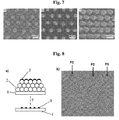
- FIG. 3a shows a scanning electron microscope (SEM) image of a typical metal nanoparticle array (1) with metal nanoparticles (8) and unwanted metal nanoparticle substructures (10).
- the substrate (4) of the metal nanoparticle array (1) consists in the present example of silicon.
- the metal was deposited on the microspheres (2) by a physical deposition process (6) (here sputtering in the vertical plane), followed by thermal decomposition (7) of the microspheres (2) with the substrate (4) at 650 ° C for one hour. was sintered.
- the thermal decomposition (7) can be carried out in an oven or by using an ethanol flame.
- Gold (Au) was chosen as the metal nanoparticle layer (5) or metal nanoparticle (8).
- the metal nanoparticles (8) and the metal nanoparticle substructures (10) are sintered with or on a substrate (4).
- metal nanoparticle substructures (10) are undesirable, they can be removed after thermal decomposition (7) by, for example, wet-chemical etching using aqueous I 2 / KI: H 2 O (1:10) as the etching solution.
- a metal nanoparticle array (1) with gold as the metal and silicon as the substrate (4) is after the wet-chemical etching and therefore without the unwanted metal nanoparticle substructures (10) in Fig. 3b ).
- the thermal decomposition (7) of the microspheres (2) and the sintering (bonding or annealing) work both in an oven and by using an ethanol flame, the latter, regardless of which side of the sintered metal nanoparticle array (1) is kept in the ethanol flame, takes place much faster ( ⁇ 2 min).
- Examples of prepared metal nanoparticle arrays (1) using an ethanol flame for 2 minutes are shown in FIGS FIGS. 4a) to 4f ).
- the FIGS. 4a) and 4b ) show here metal nanoparticle arrays (1), wherein gold (Au) was selected as the metal nanoparticle layer (5) or metal nanoparticles (8).
- the substrate (4) of the metal nanoparticle arrays (1) was for the in the FIGS.
- FIGS. 4a) and 4b ) shown arrays (1) made of quartz glass.
- the FIGS. 4c) and 4d ) show here metal nanoparticle arrays (1), wherein platinum (Pt) was selected as the metal nanoparticle layer (5) or metal nanoparticles (8).
- the substrate (4) of the metal nanoparticle arrays (1) was also made of quartz glass.
- the ethanol flame was directed to the front of the metal nanoparticle arrays (1).
- FIGS. 4e) and 4f show here metal nanoparticle arrays (1), wherein platinum (Pt) was selected as the metal nanoparticle layer (5) or metal nanoparticles (8).
- the substrate (4) of the metal nanoparticle arrays (1) here was silicon.
- the ethanol flame was directed to the back of the metal nanoparticle arrays (1).
- the size and interparticle distances (9) of the metal nanoparticles (8) can be adjusted by the thickness of the metal nanoparticle layer (5) and the diameter (D) of the microspheres (2).
- the volume of the metal nanoparticle layer (5) on each individual microsphere (2) correlates with the size of the sintered metal nanoparticle (8).
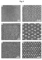
- the influence of the diameter (d) of the microspheres (2) and the influence of the thickness of the metal nanoparticle layer (5) on the size of the metal nanoparticles (8) and the interparticle distances (9) of the metal nanoparticles (8) is in FIG. 5 a) to b) shown.
- Microspheres (2) with diameters (D) between 110 nm and 1 ⁇ m enable metal nanoparticle arrays (1) with a narrow size distribution.
- SEM images of metal nanoparticle arrays (1) on silicon are shown as substrate (4) of monolayers (3) of microspheres (2) with different diameters (D).
- the diameters (D) of the microspheres (2) are for Fig. 6a ) 110 nm, for Fig. 6b ) 250 nm, for Fig. 6c ) 520 nm and for Fig. 6d ) 1 um.
- the monolayer (3) was sputtered with gold (Au) at 45 ° incidence and then sintered at 700 ° C for 1 h.
- FIG. 6e shows the difference between stochastic particles caused by dewetting of the initial ones Metal layer, which was deposited on bare ground, were generated (left in Fig. 6e ) and ordered particles produced after thermal decomposition (7) of the metal-coated microsphere monolayer (right in FIG Fig. 6e )).
- the approach proposed here is not limited to flat substrates (4): 3D objects can also be structured. This is exemplary in Fig. 6f ).
- the microspheres (2) have a diameter (D) of 520 nm.
- the inset in Fig. 6f ) is an enlargement of the selected area on the surface of the pipe.
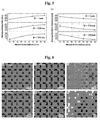
- metal nanoparticle arrays (1) on other substrates (4) or substrate types such as quartz glass ( Fig. 7a )), Sapphire ( Fig. 7b )) or polyimide ( Fig. 7c )) getting produced.
- substrates Exemplary for these substrates are SEM images in the FIG. 7 a) to c).
- the sintering temperature depends on both the metal to be used and the type of substrate (4). Temperatures in the range of 500-700 ° C were used for silicon, sapphire and quartz substrates. Although the processes work particularly well at these (higher) temperatures, they can also be used for substrates with a limited thermal budget.
- substrates (4) of polyimide can be sintered at 380 ° C, which is below the glass transition temperature of polyimide. Glass, mica, metal, ceramics or oxide materials are also useful as substrates (4).
- FIG. 8a schematically shows a multilayer (here three layers), wherein the uppermost monolayers (3) of microspheres (2) with a metal nanoparticle layer (5) is coated. After thermal decomposition (7) of the microspheres (2) and sintering (bonding or annealing), a metal-nanoparticle array (1) is also formed.
- This metal nanoparticle array (1) is called SEM in Fig. 8b ).
- Arrow 1 (P1) shows metal nanoparticles (8) of the third layer
- arrow 2 (P2) metal nanoparticles (8) of the second layer
- arrow 3 (P3) metal nanoparticles (8) of the first layer is called SEM in Fig. 8b .
Priority Applications (1)
| Application Number | Priority Date | Filing Date | Title |
|---|---|---|---|
| PL13831822T PL2931937T3 (pl) | 2012-12-14 | 2013-12-12 | Sposób wytwarzania układów nanocząstek metali |
Applications Claiming Priority (2)
| Application Number | Priority Date | Filing Date | Title |
|---|---|---|---|
| DE102012112299.7A DE102012112299A1 (de) | 2012-12-14 | 2012-12-14 | Metall-Nanopartikel-Arrays und Herstellung von Metall-Nanopartikel-Arrays |
| PCT/DE2013/100420 WO2014090229A2 (de) | 2012-12-14 | 2013-12-12 | Metall-nanopartikel-arrays und herstellung von metall-nanopartikel-arrays |
Publications (2)
| Publication Number | Publication Date |
|---|---|
| EP2931937A2 EP2931937A2 (de) | 2015-10-21 |
| EP2931937B1 true EP2931937B1 (de) | 2016-10-12 |
Family
ID=50151058
Family Applications (1)
| Application Number | Title | Priority Date | Filing Date |
|---|---|---|---|
| EP13831822.5A Active EP2931937B1 (de) | 2012-12-14 | 2013-12-12 | Verfahren zur herstellung von metall-nanopartikel-arrays |
Country Status (7)
| Country | Link |
|---|---|
| US (1) | US20150321162A1 (pl) |
| EP (1) | EP2931937B1 (pl) |
| AU (1) | AU2013358693B2 (pl) |
| DE (1) | DE102012112299A1 (pl) |
| ES (1) | ES2607204T3 (pl) |
| PL (1) | PL2931937T3 (pl) |
| WO (1) | WO2014090229A2 (pl) |
Families Citing this family (8)
| Publication number | Priority date | Publication date | Assignee | Title |
|---|---|---|---|---|
| JP7044802B2 (ja) | 2017-04-04 | 2022-03-30 | ダブリュ.エル.ゴア アンド アソシエーツ,ゲゼルシャフト ミット ベシュレンクテル ハフツング | 強化されたエラストマー及び統合電極を含む誘電複合体 |
| CN106958006A (zh) * | 2017-04-10 | 2017-07-18 | 江西科技师范大学 | 多元合金非紧密排列球形纳米颗粒阵列的制备方法 |
| CN109807345B (zh) * | 2019-01-31 | 2020-10-09 | 江南大学 | 一种光热转换点阵阵列芯片的制备和应用 |
| CN110208245B (zh) * | 2019-06-19 | 2020-09-08 | 清华大学 | 一种纸基柔性表面增强拉曼散射效应基片及其制备方法 |
| CN111929277B (zh) * | 2020-06-03 | 2021-06-01 | 中国科学院苏州生物医学工程技术研究所 | 间距可调的贵金属纳米粒子一维组装体及其在纳米传感器中的应用 |
| US11971226B2 (en) * | 2021-01-12 | 2024-04-30 | Purdue Research Foundation | High temperature thermal dual-barrier coating |
| CN114122155A (zh) * | 2021-10-15 | 2022-03-01 | 华南理工大学 | 一种含有火焰合成镍金纳米球阵列的砷化镓太阳电池及其制备 |
| CN114018304B (zh) * | 2021-11-03 | 2024-05-07 | 北京理工大学 | 一种远红外光层状传感器及制备方法 |
Family Cites Families (9)
| Publication number | Priority date | Publication date | Assignee | Title |
|---|---|---|---|---|
| US6521541B2 (en) * | 2000-08-23 | 2003-02-18 | California Institute Of Technology | Surface preparation of substances for continuous convective assembly of fine particles |
| JP3817471B2 (ja) * | 2001-12-11 | 2006-09-06 | 富士写真フイルム株式会社 | 多孔質構造体および構造体、ならびにそれらの製造方法 |
| ATE519110T1 (de) * | 2005-06-10 | 2011-08-15 | Gilupi Gmbh | Diagnostischer nanosensor und dessen verwendung in der medizin |
| US20070110671A1 (en) * | 2005-11-14 | 2007-05-17 | Danielle Chamberlin | Sensitivity enhancement of POCT devices using gold and silver nanoparticles on patterned substrates |
| US20100260946A1 (en) * | 2005-12-23 | 2010-10-14 | Jia Dongdong X | Nanostructure arrays and fabrication methods therefor |
| US8680574B2 (en) * | 2008-07-22 | 2014-03-25 | The Regents Of The University Of Michigan | Hybrid nanostructure array |
| WO2010088726A1 (en) * | 2009-02-04 | 2010-08-12 | University Of South Australia | Fabrication of nanoparticles on solid surfaces |
| US20140170310A1 (en) * | 2010-10-08 | 2014-06-19 | Li Jia | Colloidal lithography methods for fabricating microscopic and nanoscopic particle patterns on substrate surfaces |
| EP3495497B1 (en) * | 2011-04-28 | 2021-03-24 | Life Technologies Corporation | Methods and compositions for multiplex pcr |
-
2012
- 2012-12-14 DE DE102012112299.7A patent/DE102012112299A1/de not_active Withdrawn
-
2013
- 2013-12-12 AU AU2013358693A patent/AU2013358693B2/en active Active
- 2013-12-12 PL PL13831822T patent/PL2931937T3/pl unknown
- 2013-12-12 WO PCT/DE2013/100420 patent/WO2014090229A2/de active Application Filing
- 2013-12-12 ES ES13831822.5T patent/ES2607204T3/es active Active
- 2013-12-12 US US14/650,597 patent/US20150321162A1/en not_active Abandoned
- 2013-12-12 EP EP13831822.5A patent/EP2931937B1/de active Active
Also Published As
| Publication number | Publication date |
|---|---|
| ES2607204T3 (es) | 2017-03-29 |
| WO2014090229A3 (de) | 2014-08-14 |
| EP2931937A2 (de) | 2015-10-21 |
| DE102012112299A1 (de) | 2014-06-18 |
| AU2013358693A1 (en) | 2015-07-09 |
| AU2013358693B2 (en) | 2017-12-14 |
| PL2931937T3 (pl) | 2017-05-31 |
| US20150321162A1 (en) | 2015-11-12 |
| WO2014090229A2 (de) | 2014-06-19 |
Similar Documents
| Publication | Publication Date | Title |
|---|---|---|
| EP2931937B1 (de) | Verfahren zur herstellung von metall-nanopartikel-arrays | |
| DE102015004114B4 (de) | Oberflächenverstärkendes plasmonisches Substrat | |
| DE102007014538A1 (de) | Verfahren zur Erzeugung einer Antireflexionsoberfläche auf einem optischen Element sowie optische Elemente mit einer Antireflexionsoberfläche | |
| DE112016000941T5 (de) | Oberflächenverstärktes Raman-Zerstreuungselement und Verfahren zur Herstellung desselben | |
| WO2007110392A1 (de) | Breitbanding entspiegelte optische bauteile mit gekruemmten oberflaechen und deren herstellung | |
| DE102007037201B4 (de) | Element zur oberflächenverstärkten Spektroskopie und Verfahren zur Herstellung des Elements sowie seine Verwendung | |
| DE112013004006T5 (de) | Element zur oberflächenverstärkten Ramanstreuung | |
| WO2010057652A1 (de) | Nonodrähte auf substratoberflächen, verfahren zu deren herstellung sowie deren verwendung | |
| DE112017001412T5 (de) | Photovoltaische Vorrichtung zur Stimulation von Zellen und /oder elektrochemischen Reaktionen | |
| EP2501842B1 (de) | Verfahren zur räumlich aufgelösten vergrösserung von nanopartikeln auf einer substratoberfläche | |
| EP1955364A1 (de) | Verfahren zur erzeugung einer mehrzahl regelmässig angeordneter nanoverbindungen auf einem substrat | |
| AT519922A1 (de) | SERS-Substrat | |
| WO2007042520A2 (de) | Selbstorganisierte nadelartige nano-strukturen und ihre herstellung auf silizium | |
| WO2019180031A1 (de) | Verfahren zur herstellung und verwendung eines substrats mit einer funktionalisierten oberfläche | |
| DE102016208987A1 (de) | Optisches Element und EUV-Lithographiesystem | |
| EP2860151B1 (de) | Verfahren zum Herstellen einer hybriden Mikro-Nano-Struktur sowie nach diesem Verfahren hergestellte Struktur | |
| WO2008135542A1 (de) | Modifizierte multikanalstrukturen | |
| DE102004050176A1 (de) | Optoelektronisches Bauelement und Verfahren zum Steuern von Tunnelelektronenströmen durch Photonen | |
| DE10039208A1 (de) | Verfahren zur Herstellung eines Werkzeugs, das zur Schaffung optisch wirksamer Oberflächenstrukturen im sub-mum Bereich einsetzbar ist, sowie ein diesbezügliches Werkzeug | |
| DE102016118440B4 (de) | Aktivierte 3-D-Nanooberfläche, Verfahren zu ihrer Herstellung und ihre Verwendung | |
| DE102008048342B4 (de) | SERS-Substrat, Verfahren zu seiner Herstellung und Verfahren zum Detektieren eines Analyten mittels SERS | |
| WO2014086903A1 (de) | Verfahren zur herstellung von nanostrukturen | |
| WO2004038466A2 (de) | Photonische-kristall-fasern und verfahren zu ihrer herstellung | |
| DE102004052445A1 (de) | Nanostrukturträger, Verfahren zu dessen Herstellung sowie dessen Verwendung | |
| DE202010013458U1 (de) | Sonde für aperturlose Nahfeldmikroskopie und/oder für Ramanspektroskopie |
Legal Events
| Date | Code | Title | Description |
|---|---|---|---|
| PUAI | Public reference made under article 153(3) epc to a published international application that has entered the european phase |
Free format text: ORIGINAL CODE: 0009012 |
|
| 17P | Request for examination filed |
Effective date: 20150612 |
|
| AK | Designated contracting states |
Kind code of ref document: A2 Designated state(s): AL AT BE BG CH CY CZ DE DK EE ES FI FR GB GR HR HU IE IS IT LI LT LU LV MC MK MT NL NO PL PT RO RS SE SI SK SM TR |
|
| AX | Request for extension of the european patent |
Extension state: BA ME |
|
| DAX | Request for extension of the european patent (deleted) | ||
| GRAP | Despatch of communication of intention to grant a patent |
Free format text: ORIGINAL CODE: EPIDOSNIGR1 |
|
| INTG | Intention to grant announced |
Effective date: 20160506 |
|
| GRAS | Grant fee paid |
Free format text: ORIGINAL CODE: EPIDOSNIGR3 |
|
| GRAA | (expected) grant |
Free format text: ORIGINAL CODE: 0009210 |
|
| AK | Designated contracting states |
Kind code of ref document: B1 Designated state(s): AL AT BE BG CH CY CZ DE DK EE ES FI FR GB GR HR HU IE IS IT LI LT LU LV MC MK MT NL NO PL PT RO RS SE SI SK SM TR |
|
| REG | Reference to a national code |
Ref country code: GB Ref legal event code: FG4D Free format text: NOT ENGLISH |
|
| REG | Reference to a national code |
Ref country code: CH Ref legal event code: EP |
|
| REG | Reference to a national code |
Ref country code: AT Ref legal event code: REF Ref document number: 836586 Country of ref document: AT Kind code of ref document: T Effective date: 20161015 |
|
| REG | Reference to a national code |
Ref country code: IE Ref legal event code: FG4D Free format text: LANGUAGE OF EP DOCUMENT: GERMAN |
|
| REG | Reference to a national code |
Ref country code: DE Ref legal event code: R096 Ref document number: 502013005009 Country of ref document: DE |
|
| REG | Reference to a national code |
Ref country code: FR Ref legal event code: PLFP Year of fee payment: 4 |
|
| REG | Reference to a national code |
Ref country code: LT Ref legal event code: MG4D |
|
| REG | Reference to a national code |
Ref country code: NL Ref legal event code: MP Effective date: 20161012 |
|
| PG25 | Lapsed in a contracting state [announced via postgrant information from national office to epo] |
Ref country code: LV Free format text: LAPSE BECAUSE OF FAILURE TO SUBMIT A TRANSLATION OF THE DESCRIPTION OR TO PAY THE FEE WITHIN THE PRESCRIBED TIME-LIMIT Effective date: 20161012 |
|
| REG | Reference to a national code |
Ref country code: DE Ref legal event code: R082 Ref document number: 502013005009 Country of ref document: DE Representative=s name: PATENTANWAELTE GIERLICH & PISCHITZIS PARTNERSC, DE Ref country code: DE Ref legal event code: R082 Ref document number: 502013005009 Country of ref document: DE |
|
| PG25 | Lapsed in a contracting state [announced via postgrant information from national office to epo] |
Ref country code: GR Free format text: LAPSE BECAUSE OF FAILURE TO SUBMIT A TRANSLATION OF THE DESCRIPTION OR TO PAY THE FEE WITHIN THE PRESCRIBED TIME-LIMIT Effective date: 20170113 Ref country code: LT Free format text: LAPSE BECAUSE OF FAILURE TO SUBMIT A TRANSLATION OF THE DESCRIPTION OR TO PAY THE FEE WITHIN THE PRESCRIBED TIME-LIMIT Effective date: 20161012 Ref country code: SE Free format text: LAPSE BECAUSE OF FAILURE TO SUBMIT A TRANSLATION OF THE DESCRIPTION OR TO PAY THE FEE WITHIN THE PRESCRIBED TIME-LIMIT Effective date: 20161012 Ref country code: NO Free format text: LAPSE BECAUSE OF FAILURE TO SUBMIT A TRANSLATION OF THE DESCRIPTION OR TO PAY THE FEE WITHIN THE PRESCRIBED TIME-LIMIT Effective date: 20170112 |
|
| REG | Reference to a national code |
Ref country code: DE Ref legal event code: R082 Ref document number: 502013005009 Country of ref document: DE Representative=s name: PATENTANWAELTE GIERLICH & PISCHITZIS PARTNERSC, DE |
|
| PG25 | Lapsed in a contracting state [announced via postgrant information from national office to epo] |
Ref country code: IS Free format text: LAPSE BECAUSE OF FAILURE TO SUBMIT A TRANSLATION OF THE DESCRIPTION OR TO PAY THE FEE WITHIN THE PRESCRIBED TIME-LIMIT Effective date: 20170212 Ref country code: BE Free format text: LAPSE BECAUSE OF NON-PAYMENT OF DUE FEES Effective date: 20161231 Ref country code: PT Free format text: LAPSE BECAUSE OF FAILURE TO SUBMIT A TRANSLATION OF THE DESCRIPTION OR TO PAY THE FEE WITHIN THE PRESCRIBED TIME-LIMIT Effective date: 20170213 Ref country code: FI Free format text: LAPSE BECAUSE OF FAILURE TO SUBMIT A TRANSLATION OF THE DESCRIPTION OR TO PAY THE FEE WITHIN THE PRESCRIBED TIME-LIMIT Effective date: 20161012 Ref country code: RS Free format text: LAPSE BECAUSE OF FAILURE TO SUBMIT A TRANSLATION OF THE DESCRIPTION OR TO PAY THE FEE WITHIN THE PRESCRIBED TIME-LIMIT Effective date: 20161012 Ref country code: NL Free format text: LAPSE BECAUSE OF FAILURE TO SUBMIT A TRANSLATION OF THE DESCRIPTION OR TO PAY THE FEE WITHIN THE PRESCRIBED TIME-LIMIT Effective date: 20161012 Ref country code: HR Free format text: LAPSE BECAUSE OF FAILURE TO SUBMIT A TRANSLATION OF THE DESCRIPTION OR TO PAY THE FEE WITHIN THE PRESCRIBED TIME-LIMIT Effective date: 20161012 |
|
| REG | Reference to a national code |
Ref country code: DE Ref legal event code: R097 Ref document number: 502013005009 Country of ref document: DE |
|
| PG25 | Lapsed in a contracting state [announced via postgrant information from national office to epo] |
Ref country code: DK Free format text: LAPSE BECAUSE OF FAILURE TO SUBMIT A TRANSLATION OF THE DESCRIPTION OR TO PAY THE FEE WITHIN THE PRESCRIBED TIME-LIMIT Effective date: 20161012 Ref country code: CZ Free format text: LAPSE BECAUSE OF FAILURE TO SUBMIT A TRANSLATION OF THE DESCRIPTION OR TO PAY THE FEE WITHIN THE PRESCRIBED TIME-LIMIT Effective date: 20161012 Ref country code: SK Free format text: LAPSE BECAUSE OF FAILURE TO SUBMIT A TRANSLATION OF THE DESCRIPTION OR TO PAY THE FEE WITHIN THE PRESCRIBED TIME-LIMIT Effective date: 20161012 Ref country code: RO Free format text: LAPSE BECAUSE OF FAILURE TO SUBMIT A TRANSLATION OF THE DESCRIPTION OR TO PAY THE FEE WITHIN THE PRESCRIBED TIME-LIMIT Effective date: 20161012 Ref country code: EE Free format text: LAPSE BECAUSE OF FAILURE TO SUBMIT A TRANSLATION OF THE DESCRIPTION OR TO PAY THE FEE WITHIN THE PRESCRIBED TIME-LIMIT Effective date: 20161012 |
|
| PLBE | No opposition filed within time limit |
Free format text: ORIGINAL CODE: 0009261 |
|
| STAA | Information on the status of an ep patent application or granted ep patent |
Free format text: STATUS: NO OPPOSITION FILED WITHIN TIME LIMIT |
|
| PG25 | Lapsed in a contracting state [announced via postgrant information from national office to epo] |
Ref country code: BG Free format text: LAPSE BECAUSE OF FAILURE TO SUBMIT A TRANSLATION OF THE DESCRIPTION OR TO PAY THE FEE WITHIN THE PRESCRIBED TIME-LIMIT Effective date: 20170112 Ref country code: SM Free format text: LAPSE BECAUSE OF FAILURE TO SUBMIT A TRANSLATION OF THE DESCRIPTION OR TO PAY THE FEE WITHIN THE PRESCRIBED TIME-LIMIT Effective date: 20161012 |
|
| 26N | No opposition filed |
Effective date: 20170713 |
|
| PG25 | Lapsed in a contracting state [announced via postgrant information from national office to epo] |
Ref country code: MC Free format text: LAPSE BECAUSE OF FAILURE TO SUBMIT A TRANSLATION OF THE DESCRIPTION OR TO PAY THE FEE WITHIN THE PRESCRIBED TIME-LIMIT Effective date: 20161012 |
|
| REG | Reference to a national code |
Ref country code: IE Ref legal event code: MM4A |
|
| PG25 | Lapsed in a contracting state [announced via postgrant information from national office to epo] |
Ref country code: LU Free format text: LAPSE BECAUSE OF NON-PAYMENT OF DUE FEES Effective date: 20161212 |
|
| PG25 | Lapsed in a contracting state [announced via postgrant information from national office to epo] |
Ref country code: SI Free format text: LAPSE BECAUSE OF FAILURE TO SUBMIT A TRANSLATION OF THE DESCRIPTION OR TO PAY THE FEE WITHIN THE PRESCRIBED TIME-LIMIT Effective date: 20161012 Ref country code: IE Free format text: LAPSE BECAUSE OF NON-PAYMENT OF DUE FEES Effective date: 20161212 |
|
| REG | Reference to a national code |
Ref country code: FR Ref legal event code: PLFP Year of fee payment: 5 |
|
| REG | Reference to a national code |
Ref country code: BE Ref legal event code: MM Effective date: 20161231 |
|
| PG25 | Lapsed in a contracting state [announced via postgrant information from national office to epo] |
Ref country code: HU Free format text: LAPSE BECAUSE OF FAILURE TO SUBMIT A TRANSLATION OF THE DESCRIPTION OR TO PAY THE FEE WITHIN THE PRESCRIBED TIME-LIMIT; INVALID AB INITIO Effective date: 20131212 |
|
| PG25 | Lapsed in a contracting state [announced via postgrant information from national office to epo] |
Ref country code: MK Free format text: LAPSE BECAUSE OF FAILURE TO SUBMIT A TRANSLATION OF THE DESCRIPTION OR TO PAY THE FEE WITHIN THE PRESCRIBED TIME-LIMIT Effective date: 20161012 Ref country code: CY Free format text: LAPSE BECAUSE OF FAILURE TO SUBMIT A TRANSLATION OF THE DESCRIPTION OR TO PAY THE FEE WITHIN THE PRESCRIBED TIME-LIMIT Effective date: 20161012 |
|
| PG25 | Lapsed in a contracting state [announced via postgrant information from national office to epo] |
Ref country code: MT Free format text: LAPSE BECAUSE OF FAILURE TO SUBMIT A TRANSLATION OF THE DESCRIPTION OR TO PAY THE FEE WITHIN THE PRESCRIBED TIME-LIMIT Effective date: 20161012 |
|
| PG25 | Lapsed in a contracting state [announced via postgrant information from national office to epo] |
Ref country code: TR Free format text: LAPSE BECAUSE OF FAILURE TO SUBMIT A TRANSLATION OF THE DESCRIPTION OR TO PAY THE FEE WITHIN THE PRESCRIBED TIME-LIMIT Effective date: 20161012 |
|
| PG25 | Lapsed in a contracting state [announced via postgrant information from national office to epo] |
Ref country code: AL Free format text: LAPSE BECAUSE OF FAILURE TO SUBMIT A TRANSLATION OF THE DESCRIPTION OR TO PAY THE FEE WITHIN THE PRESCRIBED TIME-LIMIT Effective date: 20161012 |
|
| PGFP | Annual fee paid to national office [announced via postgrant information from national office to epo] |
Ref country code: FR Payment date: 20211220 Year of fee payment: 9 Ref country code: GB Payment date: 20211222 Year of fee payment: 9 Ref country code: AT Payment date: 20211216 Year of fee payment: 9 |
|
| PGFP | Annual fee paid to national office [announced via postgrant information from national office to epo] |
Ref country code: CH Payment date: 20211222 Year of fee payment: 9 |
|
| PGFP | Annual fee paid to national office [announced via postgrant information from national office to epo] |
Ref country code: PL Payment date: 20211201 Year of fee payment: 9 |
|
| PGFP | Annual fee paid to national office [announced via postgrant information from national office to epo] |
Ref country code: DE Payment date: 20211220 Year of fee payment: 9 |
|
| PGFP | Annual fee paid to national office [announced via postgrant information from national office to epo] |
Ref country code: IT Payment date: 20211230 Year of fee payment: 9 Ref country code: ES Payment date: 20220119 Year of fee payment: 9 |
|
| P01 | Opt-out of the competence of the unified patent court (upc) registered |
Effective date: 20230514 |
|
| REG | Reference to a national code |
Ref country code: DE Ref legal event code: R119 Ref document number: 502013005009 Country of ref document: DE |
|
| REG | Reference to a national code |
Ref country code: CH Ref legal event code: PL |
|
| REG | Reference to a national code |
Ref country code: AT Ref legal event code: MM01 Ref document number: 836586 Country of ref document: AT Kind code of ref document: T Effective date: 20221212 |
|
| GBPC | Gb: european patent ceased through non-payment of renewal fee |
Effective date: 20221212 |
|
| PG25 | Lapsed in a contracting state [announced via postgrant information from national office to epo] |
Ref country code: LI Free format text: LAPSE BECAUSE OF NON-PAYMENT OF DUE FEES Effective date: 20221231 Ref country code: GB Free format text: LAPSE BECAUSE OF NON-PAYMENT OF DUE FEES Effective date: 20221212 Ref country code: DE Free format text: LAPSE BECAUSE OF NON-PAYMENT OF DUE FEES Effective date: 20230701 Ref country code: CH Free format text: LAPSE BECAUSE OF NON-PAYMENT OF DUE FEES Effective date: 20221231 Ref country code: AT Free format text: LAPSE BECAUSE OF NON-PAYMENT OF DUE FEES Effective date: 20221212 |
|
| PG25 | Lapsed in a contracting state [announced via postgrant information from national office to epo] |
Ref country code: FR Free format text: LAPSE BECAUSE OF NON-PAYMENT OF DUE FEES Effective date: 20221231 |
|
| REG | Reference to a national code |
Ref country code: ES Ref legal event code: FD2A Effective date: 20240130 |
|
| PG25 | Lapsed in a contracting state [announced via postgrant information from national office to epo] |
Ref country code: IT Free format text: LAPSE BECAUSE OF NON-PAYMENT OF DUE FEES Effective date: 20221212 |
|
| PG25 | Lapsed in a contracting state [announced via postgrant information from national office to epo] |
Ref country code: ES Free format text: LAPSE BECAUSE OF NON-PAYMENT OF DUE FEES Effective date: 20221213 |
|
| PG25 | Lapsed in a contracting state [announced via postgrant information from national office to epo] |
Ref country code: ES Free format text: LAPSE BECAUSE OF NON-PAYMENT OF DUE FEES Effective date: 20221213 |