EP2923955A2 - Dispositif de traitement de produits alimentaires - Google Patents
Dispositif de traitement de produits alimentaires Download PDFInfo
- Publication number
- EP2923955A2 EP2923955A2 EP15161101.9A EP15161101A EP2923955A2 EP 2923955 A2 EP2923955 A2 EP 2923955A2 EP 15161101 A EP15161101 A EP 15161101A EP 2923955 A2 EP2923955 A2 EP 2923955A2
- Authority
- EP
- European Patent Office
- Prior art keywords
- unit
- frame
- conveyor
- product conveyor
- working unit
- Prior art date
- Legal status (The legal status is an assumption and is not a legal conclusion. Google has not performed a legal analysis and makes no representation as to the accuracy of the status listed.)
- Granted
Links
- 238000012545 processing Methods 0.000 title claims abstract description 31
- 235000013305 food Nutrition 0.000 title claims abstract description 22
- 238000012423 maintenance Methods 0.000 claims description 18
- 238000004806 packaging method and process Methods 0.000 claims description 13
- 230000008093 supporting effect Effects 0.000 claims description 8
- 230000001681 protective effect Effects 0.000 description 13
- 238000010276 construction Methods 0.000 description 5
- 238000013461 design Methods 0.000 description 5
- 238000012546 transfer Methods 0.000 description 4
- 238000004140 cleaning Methods 0.000 description 3
- 238000004519 manufacturing process Methods 0.000 description 3
- 238000000034 method Methods 0.000 description 3
- 239000002985 plastic film Substances 0.000 description 3
- 229920006255 plastic film Polymers 0.000 description 3
- 239000002245 particle Substances 0.000 description 2
- 238000003856 thermoforming Methods 0.000 description 2
- 230000006978 adaptation Effects 0.000 description 1
- 235000013351 cheese Nutrition 0.000 description 1
- 238000006243 chemical reaction Methods 0.000 description 1
- 230000003749 cleanliness Effects 0.000 description 1
- 238000005520 cutting process Methods 0.000 description 1
- 230000001419 dependent effect Effects 0.000 description 1
- 239000003599 detergent Substances 0.000 description 1
- 238000011161 development Methods 0.000 description 1
- 230000018109 developmental process Effects 0.000 description 1
- 238000009826 distribution Methods 0.000 description 1
- 230000003670 easy-to-clean Effects 0.000 description 1
- 239000012530 fluid Substances 0.000 description 1
- 238000012994 industrial processing Methods 0.000 description 1
- 235000013372 meat Nutrition 0.000 description 1
- 235000013580 sausages Nutrition 0.000 description 1
- 238000003892 spreading Methods 0.000 description 1
- 230000006641 stabilisation Effects 0.000 description 1
- 238000011105 stabilization Methods 0.000 description 1
Images


Classifications
-
- B—PERFORMING OPERATIONS; TRANSPORTING
- B65—CONVEYING; PACKING; STORING; HANDLING THIN OR FILAMENTARY MATERIAL
- B65G—TRANSPORT OR STORAGE DEVICES, e.g. CONVEYORS FOR LOADING OR TIPPING, SHOP CONVEYOR SYSTEMS OR PNEUMATIC TUBE CONVEYORS
- B65G35/00—Mechanical conveyors not otherwise provided for
-
- B—PERFORMING OPERATIONS; TRANSPORTING
- B65—CONVEYING; PACKING; STORING; HANDLING THIN OR FILAMENTARY MATERIAL
- B65B—MACHINES, APPARATUS OR DEVICES FOR, OR METHODS OF, PACKAGING ARTICLES OR MATERIALS; UNPACKING
- B65B35/00—Supplying, feeding, arranging or orientating articles to be packaged
- B65B35/10—Feeding, e.g. conveying, single articles
- B65B35/24—Feeding, e.g. conveying, single articles by endless belts or chains
-
- B—PERFORMING OPERATIONS; TRANSPORTING
- B29—WORKING OF PLASTICS; WORKING OF SUBSTANCES IN A PLASTIC STATE IN GENERAL
- B29C—SHAPING OR JOINING OF PLASTICS; SHAPING OF MATERIAL IN A PLASTIC STATE, NOT OTHERWISE PROVIDED FOR; AFTER-TREATMENT OF THE SHAPED PRODUCTS, e.g. REPAIRING
- B29C51/00—Shaping by thermoforming, i.e. shaping sheets or sheet like preforms after heating, e.g. shaping sheets in matched moulds or by deep-drawing; Apparatus therefor
- B29C51/26—Component parts, details or accessories; Auxiliary operations
- B29C51/261—Handling means, e.g. transfer means, feeding means
-
- B—PERFORMING OPERATIONS; TRANSPORTING
- B65—CONVEYING; PACKING; STORING; HANDLING THIN OR FILAMENTARY MATERIAL
- B65B—MACHINES, APPARATUS OR DEVICES FOR, OR METHODS OF, PACKAGING ARTICLES OR MATERIALS; UNPACKING
- B65B35/00—Supplying, feeding, arranging or orientating articles to be packaged
- B65B35/30—Arranging and feeding articles in groups
-
- B—PERFORMING OPERATIONS; TRANSPORTING
- B65—CONVEYING; PACKING; STORING; HANDLING THIN OR FILAMENTARY MATERIAL
- B65B—MACHINES, APPARATUS OR DEVICES FOR, OR METHODS OF, PACKAGING ARTICLES OR MATERIALS; UNPACKING
- B65B47/00—Apparatus or devices for forming pockets or receptacles in or from sheets, blanks, or webs, comprising essentially a die into which the material is pressed or a folding die through which the material is moved
- B65B47/04—Apparatus or devices for forming pockets or receptacles in or from sheets, blanks, or webs, comprising essentially a die into which the material is pressed or a folding die through which the material is moved by application of mechanical pressure
-
- B—PERFORMING OPERATIONS; TRANSPORTING
- B65—CONVEYING; PACKING; STORING; HANDLING THIN OR FILAMENTARY MATERIAL
- B65B—MACHINES, APPARATUS OR DEVICES FOR, OR METHODS OF, PACKAGING ARTICLES OR MATERIALS; UNPACKING
- B65B59/00—Arrangements to enable machines to handle articles of different sizes, to produce packages of different sizes, to vary the contents of packages, to handle different types of packaging material, or to give access for cleaning or maintenance purposes
-
- B—PERFORMING OPERATIONS; TRANSPORTING
- B65—CONVEYING; PACKING; STORING; HANDLING THIN OR FILAMENTARY MATERIAL
- B65B—MACHINES, APPARATUS OR DEVICES FOR, OR METHODS OF, PACKAGING ARTICLES OR MATERIALS; UNPACKING
- B65B9/00—Enclosing successive articles, or quantities of material, e.g. liquids or semiliquids, in flat, folded, or tubular webs of flexible sheet material; Subdividing filled flexible tubes to form packages
- B65B9/02—Enclosing successive articles, or quantities of material between opposed webs
- B65B9/04—Enclosing successive articles, or quantities of material between opposed webs one or both webs being formed with pockets for the reception of the articles, or of the quantities of material
-
- B—PERFORMING OPERATIONS; TRANSPORTING
- B65—CONVEYING; PACKING; STORING; HANDLING THIN OR FILAMENTARY MATERIAL
- B65B—MACHINES, APPARATUS OR DEVICES FOR, OR METHODS OF, PACKAGING ARTICLES OR MATERIALS; UNPACKING
- B65B9/00—Enclosing successive articles, or quantities of material, e.g. liquids or semiliquids, in flat, folded, or tubular webs of flexible sheet material; Subdividing filled flexible tubes to form packages
- B65B9/10—Enclosing successive articles, or quantities of material, in preformed tubular webs, or in webs formed into tubes around filling nozzles, e.g. extruded tubular webs
-
- B—PERFORMING OPERATIONS; TRANSPORTING
- B65—CONVEYING; PACKING; STORING; HANDLING THIN OR FILAMENTARY MATERIAL
- B65G—TRANSPORT OR STORAGE DEVICES, e.g. CONVEYORS FOR LOADING OR TIPPING, SHOP CONVEYOR SYSTEMS OR PNEUMATIC TUBE CONVEYORS
- B65G47/00—Article or material-handling devices associated with conveyors; Methods employing such devices
- B65G47/22—Devices influencing the relative position or the attitude of articles during transit by conveyors
- B65G47/26—Devices influencing the relative position or the attitude of articles during transit by conveyors arranging the articles, e.g. varying spacing between individual articles
Definitions
- production lines are often used, which next to a cutting device such as a high-performance slicer several juxtaposed conveyors such as portioning, Aukahdroiter, spreading conveyor, distribution conveyor, buffer conveyor and infeed conveyor.
- a packaging machine which, from a provided plastic film web by means of a deep-drawing process, makes available an arrangement of packages in which the products or product portions are usually inserted in formats by means of an infeed conveyor.
- a deep-drawing unit packaging machine is also referred to in the art as a "thermoformer”.
- the loading conveyor is often referred to as "depositor" shortened.
- the insert must be positioned above the thermoformer, which is easily possible with laterally projecting arrangement of the conveyor unit.
- a "device for processing food products” in the sense of the invention should generally be understood to mean any device which serves for processing, processing and / or handling of individual or portioned food products. Furthermore, it is understood that an arrangement of a product conveyor with laterally projecting conveyor unit and a at least partially arranged under the conveyor unit working unit can be used in many ways in the environment of food processing and processing, so not only in the form of a combination of depositors and thermoformers. For example, the work unit could also be another product conveyor.
- the conveyor units of an insert must be suitable for format-rate promotion and therefore have a working width of 40 cm to 80 cm, so project relatively strong laterally.
- the design must also be sufficiently rigid, as in operation vibrations that could affect proper alignment of the products or portions are unacceptable. At the same time, good accessibility of all machine areas for cleaning and maintenance work must be guaranteed.
- the relatively large thermoforming tool must be able to be inserted and removed upwards and sideways.
- the frames because of the design-related top-to-bottom strength, the frames generally need to have a high level of stability, which is why they are correspondingly heavy - often up to several tons.
- the frame of the product conveyor is supported or held by a mechanical connection to the working unit.
- the frame is also fixed to the work unit.
- the product conveyor is integrated into the working unit.
- the mass and stiffness or stability of the unit of work can be used to add extra stability to the frame of the product conveyor.
- this allows for a lighter and more compact design for the product conveyor.
- the invention is based on the recognition that in many application situations of the aforementioned type it is not necessary to design the working unit and the product conveyor as independent, stable machines, since they are always used together in any case.
- the art has hitherto been based on the idea of providing completely separate constructions, for example for thermoformers and inserts.
- the frame of the product conveyor extends at least partially into a free space defined by the working unit.
- the frame can thus develop a higher supporting effect than when the product conveyor is parked next to the working unit.
- this can use the free space of the work unit.
- the invention is therefore the general idea to use a to be arranged under a product conveyor with laterally projecting conveyor unit working unit to build the product conveyor itself more compact and easier.
- the mass, rigidity or stability and / or the enclosed space of the working unit can be used to improve the support of the product conveyor.
- the free space is preferably located in the area of a standing area and / or in a region near the floor, in particular between separate feet of the working unit.
- Working units such as thermoformers are often placed on feet, between which there is sufficient space for receiving a, for example, horizontally extending support member of the product conveyor.
- the designed as a supporting frame frame of the product conveyor may have a arranged next to the work unit, in particular vertical support section and extending into the free space, in particular horizontally projecting, stand section.
- the frame could for example have an L-shaped cross-section. This allows a particularly compact construction, in particular in the absence of a stand section on the side facing away from the working unit of the support section.
- a horizontally extending stand section with a low overall height, a comparatively small free space below the working unit can also be used.
- the frame of the product conveyor may be supported in horizontal and / or vertical direction on the working unit.
- a support in horizontal and in the vertical direction allows a particularly high stability of the overall device.
- the frame is supported with at least one horizontal frame region and / or with at least one vertical frame region on the working unit.
- a specific embodiment of the invention provides that the product conveyor is completely carried by the working unit. This is a departure from the common principle of always constructing product conveyors as standalone devices. Ultimately, in the aforementioned embodiment, therefore, a working unit with an integrated product conveyor, that is, for example, a thermoformer with an integrated insert, is provided.
- the frame of the product conveyor may be mounted at a distance from a stand and / or floor at the work unit. This means that the product conveyor can only be supported by the work unit on the stand or on the ground. The absence of own feet for the product conveyor allows a considerable saving of weight and space. In addition, a food processing machine with few feet is particularly easy to clean.
- the frame of the product conveyor may be supported both on a standing surface and / or on the floor as well as on the working unit. This allows a particularly stable overall construction.
- a preferred embodiment of the invention provides that the frame of the product conveyor alone is not sufficient for a stable carrying the conveyor unit, ie that the frame provides only together with the working unit sufficient rigidity and stability for carrying and operating the conveyor unit.
- the product conveyor is simply equipped with a lightweight frame to save weight, cost and space.
- the desired stability arises only by the support on the working unit and utilization of their mass and rigidity or stability.
- a further embodiment of the invention provides that the frame of the product conveyor is fixed to a, in particular lateral, holding frame of the working unit.
- the frame of the product conveyor may be hung or screwed to a frame of the work unit.
- Many working units have externally accessible frame members, such as profile beams, which can be used to attach the frame of the product conveyor.
- the conveying unit of the product conveyor is movable with respect to the frame between a lowered operating position and a raised maintenance position.
- the conveyor unit When the conveyor unit is in the raised service position, it provides easy and safe access to the underlying work unit, for example, to replace a thermoforming tool. It is not necessary here to set aside the product conveyor as a whole or to carry out complex assembly work.
- the conveying unit of the product conveyor can be moved away from the working unit, in particular by pivoting or folding away.
- a hinge connection may be provided, which allows a pivoting or folding away of the conveyor unit relative to the frame in a stationary frame, in particular about a pivot axis extending parallel to the conveying direction.
- a further embodiment of the invention provides that a functional unit of the working unit is movable together with the conveyor unit, wherein, preferably, the functional unit on a bottom, in the lower area and / or below the Conveyor unit is attached.
- the functional unit may be, for example, a protective cover of the working unit, which is to be removed during maintenance.
- a protective cover can be moved together with the delivery unit, for example, between an operating position and a maintenance position, it is not necessary for a user to remove the protective cover separately.
- this can be permanently ensured in all operating positions that product residues or detergent drops do not reach down into the area of the working unit. The handling of the device can thus be simplified and its cleanliness can be further improved.
- the functional unit In an operating position, the functional unit preferably provides an operating function of the working unit and at the same time an operating function of the conveying unit.
- the functional unit may form a protective cover for a thermoformer and at the same time a collecting device for deflecting or collecting particles which fall off the conveyor unit above it.
- a separate construction of thermoformer and insert generally it is necessary to provide both the thermoformer with a protective cover and the insert in the area below the conveyor unit with a collecting plate or the like.
- the working unit may comprise means or parts of means for automatically packaging the conveyed products, for example a so-called thermoformer.
- the working unit may have other and / or further facilities for processing and processing the subsidized food products.
- the product conveyor is preferably designed to load the conveyed products into respective packaging units provided by the automatic packaging device.
- designed device thus forms a unit of a packaging machine and an associated infeed conveyor.
- Such units are often needed in the field of food processing and need according to the invention due the modular structure of product conveyor on the one hand and work unit on the other hand to be created on site directly on site.
- the product conveyor may be configured to group products or individual portions, portions to form rows of products or portions comprising individual products, and / or portions to form portions of products or portions comprising individual products.
- positioning means are provided, by means of which the position of the frame, in particular of horizontal and / or vertical frame regions, relative to the working unit, especially when supported on the work unit or held frame adjustable and held in a set state
- the positioning means are variable in their defining a distance between the frame and the working unit length.
- elements or parts of the frame for example horizontally or vertically extending frame parts of the product conveyor, may be variable in length in order to adapt the product conveyor to the working unit or to its means for supporting or holding or fixing the product conveyor.
- the frame engages below or engages around the working unit, wherein in particular a horizontally projecting frame region of the frame extends from one side of the working unit below it to the opposite side and is fixed on this opposite side of the working unit.
- a particularly evenly distributed force introduction into the frame of the working unit can be realized.
- additional feet for the product conveyor can be omitted, whereby a good cleaning of the floor or the floor space is facilitated.
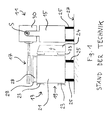
- the prior art food product processing apparatus shown includes a product conveyor 11 and a work unit 13 in the form of an automatic packaging machine.
- the product conveyor 11 comprises a base frame or frame 15 and a conveyor unit 17 fixed to the frame 15.
- the conveyor unit 17 comprises one or more belt or belt conveyors and is laterally cantilevered as shown the frame 15 is arranged.
- the working unit 13 is located below the conveyor unit 17 and also comprises a base frame or a frame 19, which is here composed of cross members 21 with attached thereto, profile-like side members 23.
- a supply and control unit 24 is mounted in the form of a cabinet. Both the product conveyor 11 and the working unit 13 are parked by means of feet 25 on the floor 27.
- the device shown is integrated into a prepackaged food production line and serves to package product slices cut open by a high-performance slicer, not shown, in a batchwise format.
- the product conveyor 11 is accordingly intended to convey delivered product portions in a direction perpendicular to the drawing plane conveying direction and to insert them in an arrangement of provided by the working unit 13 packaging.
- the working unit 13 provides an arrangement of packaging troughs at a transfer section 28 from a provided plastic film web by means of a deep drawing process. After inserting the product portions, the packaging trays are closed with a plastic film web also provided. Above the transfer section 28 is a protective cover 29th
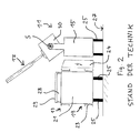
- a housing 30 of the conveyor unit 17 is mounted pivotably on the frame 15 about a pivot axis S. It can thus proceed from the in Fig. 1 illustrated lowered operating position in the in Fig. 2 shown raised maintenance position to be pivoted.
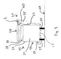
- the product conveyor 31 and the working unit 13 are the product conveyor 31 and the working unit 13 not designed as separate machines, but merged into one unit.
- the frame 35 of the product conveyor 31 is fixed to the work unit 13 at a distance from the stand surface 27, as shown. That is, the product conveyor 31 is completely supported by the process cartridge 13 and supported thereon in both the horizontal and vertical directions.
- the mass and rigidity of the unit of work 13 is sufficient to provide stability to the entire unit.
- the conveyor unit 37 of the product conveyor 31 is in the in Fig. 3 to 5 illustrated embodiment of the invention also between a lowered operating position and a raised maintenance position pivoted.
- the conveyor unit 37 is here designed as a tape cassette in which the shafts of the corresponding belt or belt conveyor are mounted. Thus, can be dispensed with a pivotable housing of the conveyor unit 37.
- a protective cover 39 is disposed above the transfer section 28 of the working unit 13. If necessary, however, the protective cover 39 may be fastened or attachable to the underside 40 of the conveyor unit 37 so that it can be pivoted together with the latter between the operating position and the maintenance position (FIG. Fig. 5 ). In case of maintenance, one operation can thus be saved.
- the protective cover 39 is used in the in Fig. 3 to 5 device according to the invention additionally shown as a collecting device for collecting such particles falling from the conveyor unit 37.
- the working unit 13 is also protected from cleaning fluid when, for reasons of hygiene, the product conveyor 31 has to be thoroughly cleaned at regular intervals.
- FIG. 3 A variant of this embodiment is in Fig. 3 indicated by a dashed line.
- this variant is not shown for the sake of simplicity.
- the frame 35 has a designed as a horizontally projecting frame portion arm 67.
- the arm 67 extends from the vertically extending frame portion on the one side of the working unit 13 extends from the bottom of the working unit 13 along the opposite side and is fixed there.
- the working unit 13 is surrounded by the frame 35 in particular like a clip.
- a particularly evenly distributed force introduction over the frame 35 of the product conveyor 31 can be achieved in the working unit 13 in an advantageous manner. Additional feet are not required in this variant.
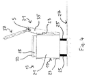
- the Fig. 6 to 8 show an alternative embodiment of a device according to the invention for processing food products.
- the apparatus also comprises a product conveyor 41 and a working unit 13, but differs from the embodiment described above in that the frame 45 of the product conveyor 41 is formed as a supporting frame.
- the frame 45 of the product conveyor 41 comprises a vertical support portion 47 and a horizontal stand portion 49.
- the frame 45 has a substantially L-shaped cross section.
- the width of the stand portion 49 is greater than the width of the laterally projecting conveyor unit 37, so that a sufficient stability is ensured for the product conveyor 41.
- the stand portion 49 has only a small height, so that it can be arranged in reaching into the free space 60 formed between the feet 25 of the working unit 13.
- the width of the overall apparatus may be greater than that in FIG Fig. 1 and 2 shown arrangement can be reduced. If necessary, the stand section 49 may be attached to the work unit 13 for additional stabilization.
- the conveyor unit 37 designed as a tape cassette and between a lowered operating position ( Fig. 6 ) as well as a raised one Maintenance position ( Fig. 7 and 8th ) pivotable.
- the protective cover 39 may be fastened or attachable to the underside 40 of the conveyor unit 37.
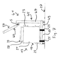
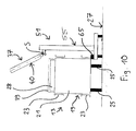
- the frame 55 of the product conveyor 51 is supported both on the bottom 27 and on the working unit 13. Specifically, the frame 55 is attached by means of a connecting element 65 on one of the side support 23, for example, screwed to this. Due to this attachment, the frame 55 need not necessarily be stable, so that it can be designed to be lighter and smaller accordingly. Also at the in Fig. 9 and 10 illustrated embodiment, the conveyor unit 37 is designed as a tape cassette and between a lowered operating position ( Fig. 9 ) and a raised maintenance position ( Fig. 10 ) pivotable. The protective cover 39 can in turn be attached to the underside 40 of the conveyor unit 37, if necessary, which is shown in FIG Fig. 9 and 10 but not shown.
Priority Applications (1)
| Application Number | Priority Date | Filing Date | Title |
|---|---|---|---|
| PL15161101.9T PL2923955T5 (pl) | 2014-03-28 | 2015-03-26 | Urządzenie do przetwórstwa produktów spożywczych |
Applications Claiming Priority (1)
| Application Number | Priority Date | Filing Date | Title |
|---|---|---|---|
| DE102014104387.1A DE102014104387A1 (de) | 2014-03-28 | 2014-03-28 | Vorrichtung zur Verarbeitung von Lebensmittelprodukten |
Publications (4)
| Publication Number | Publication Date |
|---|---|
| EP2923955A2 true EP2923955A2 (fr) | 2015-09-30 |
| EP2923955A3 EP2923955A3 (fr) | 2015-12-09 |
| EP2923955B1 EP2923955B1 (fr) | 2016-10-19 |
| EP2923955B2 EP2923955B2 (fr) | 2022-11-30 |
Family
ID=52780880
Family Applications (1)
| Application Number | Title | Priority Date | Filing Date |
|---|---|---|---|
| EP15161101.9A Active EP2923955B2 (fr) | 2014-03-28 | 2015-03-26 | Dispositif de traitement de produits alimentaires |
Country Status (5)
| Country | Link |
|---|---|
| US (2) | US11383935B2 (fr) |
| EP (1) | EP2923955B2 (fr) |
| DE (1) | DE102014104387A1 (fr) |
| ES (1) | ES2611578T5 (fr) |
| PL (1) | PL2923955T5 (fr) |
Cited By (2)
| Publication number | Priority date | Publication date | Assignee | Title |
|---|---|---|---|---|
| EP3381820A1 (fr) * | 2017-03-30 | 2018-10-03 | MULTIVAC Sepp Haggenmüller SE & Co. KG | Machine d'emballage à couvercles de protection empilables |
| EP3476774A1 (fr) * | 2017-10-26 | 2019-05-01 | Weber Maschinenbau GmbH Breidenbach | Transporteur |
Families Citing this family (1)
| Publication number | Priority date | Publication date | Assignee | Title |
|---|---|---|---|---|
| DE102017108991A1 (de) | 2017-04-26 | 2018-10-31 | Weber Maschinenbau Gmbh Breidenbach | Verpacken von lebensmittelprodukten |
Family Cites Families (30)
| Publication number | Priority date | Publication date | Assignee | Title |
|---|---|---|---|---|
| US3561512A (en) * | 1968-04-15 | 1971-02-09 | Ward Foods Inc | Pineapple-treating apparatus |
| GB1512509A (en) * | 1974-05-23 | 1978-06-01 | Shell Bv | Fungicides |
| US4034536A (en) | 1976-06-11 | 1977-07-12 | Mahaffy & Harder Engineering Company | Packaging apparatus and techniques |
| US4548108A (en) * | 1983-08-08 | 1985-10-22 | Cashin Systems Corporation | Slicing machine |
| KR0148348B1 (ko) * | 1989-04-07 | 1998-12-15 | 라르스-에케 포르스베르크 | 연속 이송 열성형 방법 및 장치 |
| GB2241682B (en) | 1990-03-05 | 1993-11-03 | Arnott Handling Equipment Limi | Conveyor assembly |
| US5271304A (en) * | 1990-07-03 | 1993-12-21 | Carruthers Equipment Co. | Automatic food slicing machine |
| CH683176A5 (de) | 1991-04-25 | 1994-01-31 | Buehler S A R L | Bandförderer. |
| CA2133953A1 (fr) * | 1992-04-23 | 1993-11-11 | Joseph Carey | Machine a trancher la viande, et sa methode d'utilisation |
| DE4218720A1 (de) * | 1992-06-06 | 1993-12-09 | Bielomatik Leuze & Co | Schließvorrichtung für Packgut-Umhüllungen |
| DE4334238A1 (de) * | 1993-10-04 | 1995-04-06 | Stimpfl Christof | Vorrichtung zum Verpacken von Gegenständen |
| US5444750A (en) * | 1993-11-09 | 1995-08-22 | Bass Gambling Supplies Inc. | Tally punch machine |
| DE4407639A1 (de) | 1994-03-08 | 1995-09-14 | Tetra Laval Convenience Food | Verfahren und Tiefzieheinrichtung zum Herstellen einer Folienschale |
| NZ284030A (en) * | 1994-05-03 | 1998-03-25 | Inauen Masch Ag | Vacuum packaging machine, movement of the cover involves a rectilinear and a swivelling component prevailing in, respectively, one and the other end region of its movement |
| US5499719A (en) * | 1995-02-13 | 1996-03-19 | Formax, Inc. | Takeaway/correction conveyor system for food product machine |
| DE29718630U1 (de) * | 1997-10-21 | 1997-12-11 | Ruehle Gmbh | Würfel- und Streifenschneidemaschine |
| FR2771080B1 (fr) | 1997-11-18 | 2000-01-28 | Sogem Agro | Convoyeur a bande sans fin motorisee |
| DE29801161U1 (de) * | 1998-01-24 | 1998-03-05 | Magurit Gefrierschneider Gmbh | Zerkleinerungsvorrichtung für Nahrungsmittel |
| FR2821833A1 (fr) | 2001-03-06 | 2002-09-13 | Bernard Jean Michel Philippe | Convoyeur a bande |
| US6585477B1 (en) * | 2001-06-22 | 2003-07-01 | Lawrence Equipment | Counter-stacker for flat food products |
| DE10143506A1 (de) | 2001-09-05 | 2003-05-08 | Weber Maschb Gmbh & Co Kg | Verteilervorrichtung |
| DE10201182A1 (de) | 2002-01-14 | 2003-07-24 | Cfs Gmbh Kempten | Positioniersystem |
| DE10238482A1 (de) | 2002-05-23 | 2003-12-04 | Cfs Kempten Gmbh | Einlegevorrichtung |
| DE102006020368A1 (de) | 2006-02-09 | 2007-08-16 | Cfs Germany Gmbh | Verpackungsmaschine mit einer Kettenreinigung |
| DE102006006523A1 (de) | 2006-02-10 | 2007-08-16 | Cfs Germany Gmbh | Verpackungsmaschine mit zwei hintereinander angeordneten Transportketten |
| FR2900858B1 (fr) † | 2006-05-12 | 2008-06-27 | Ermatec Sarl | Machine de decoupe pour produits agroalimentaires et machine de realisation d'emballages associee |
| DE102008015689A1 (de) * | 2008-03-26 | 2009-10-01 | Multivac Sepp Haggenmüller Gmbh & Co. Kg | Verpackungsmaschine |
| DE102010034676A1 (de) | 2010-08-18 | 2012-02-23 | Weber Maschinenbau Gmbh Breidenbach | Fördern von Gegenständen |
| IT1404664B1 (it) * | 2010-12-22 | 2013-11-29 | Grasselli | Apparecchiatura per deposizione in contenitori di alimenti affettati |
| DE102011101101A1 (de) | 2011-05-10 | 2014-01-30 | Bizerba Gmbh & Co Kg | Schneidemaschine |
-
2014
- 2014-03-28 DE DE102014104387.1A patent/DE102014104387A1/de active Pending
-
2015
- 2015-03-26 PL PL15161101.9T patent/PL2923955T5/pl unknown
- 2015-03-26 US US14/669,548 patent/US11383935B2/en active Active
- 2015-03-26 ES ES15161101T patent/ES2611578T5/es active Active
- 2015-03-26 EP EP15161101.9A patent/EP2923955B2/fr active Active
-
2022
- 2022-02-04 US US17/665,029 patent/US20220153527A1/en active Pending
Non-Patent Citations (1)
| Title |
|---|
| None |
Cited By (5)
| Publication number | Priority date | Publication date | Assignee | Title |
|---|---|---|---|---|
| EP3381820A1 (fr) * | 2017-03-30 | 2018-10-03 | MULTIVAC Sepp Haggenmüller SE & Co. KG | Machine d'emballage à couvercles de protection empilables |
| US10899486B2 (en) | 2017-03-30 | 2021-01-26 | Multivac Sepp Haggenmüller Se & Co. Kg | Packaging machine with stackable protective covers |
| EP3476774A1 (fr) * | 2017-10-26 | 2019-05-01 | Weber Maschinenbau GmbH Breidenbach | Transporteur |
| US10717609B2 (en) | 2017-10-26 | 2020-07-21 | Weber Maschinenbau Breidenbach GmbH | Conveying device |
| EP3476774B1 (fr) | 2017-10-26 | 2022-12-07 | Weber Maschinenbau GmbH Breidenbach | Transporteur |
Also Published As
| Publication number | Publication date |
|---|---|
| ES2611578T3 (es) | 2017-05-09 |
| EP2923955B1 (fr) | 2016-10-19 |
| US20150274431A1 (en) | 2015-10-01 |
| DE102014104387A1 (de) | 2015-10-01 |
| US11383935B2 (en) | 2022-07-12 |
| EP2923955B2 (fr) | 2022-11-30 |
| PL2923955T3 (pl) | 2017-05-31 |
| PL2923955T5 (pl) | 2023-03-27 |
| US20220153527A1 (en) | 2022-05-19 |
| ES2611578T5 (es) | 2023-02-17 |
| EP2923955A3 (fr) | 2015-12-09 |
Similar Documents
| Publication | Publication Date | Title |
|---|---|---|
| EP3476774B1 (fr) | Transporteur | |
| EP2794433B1 (fr) | Installation de préparation des commandes et procédé de préparation des marchandises commandées | |
| WO2016102417A1 (fr) | Dispositif pour déplacer des objets | |
| EP2527262B1 (fr) | Machine pour le remplissage de récipients | |
| EP3315423B1 (fr) | Machine d'emballage par emboutissage | |
| EP3315420B1 (fr) | Machine d'emballage par emboutissage | |
| EP2923955B1 (fr) | Dispositif de traitement de produits alimentaires | |
| EP3009379B1 (fr) | Dispositif de convoyage dote d'un organe de transport a extension plane | |
| EP3025971B1 (fr) | Dispositif de remplissage et de changement destine a remplir des recipients avec des produits en vrac | |
| DE102013100806B4 (de) | Mehrspurige Fördervorrichtung | |
| DE102010015367B4 (de) | Kreismesserschneidemaschine | |
| DE102015210052A1 (de) | Übergabevorrichtung und Verfahren | |
| DE102018204035A1 (de) | Bandförderer mit abstreiferbaugruppe | |
| EP4281397A1 (fr) | Système de transport pour transporter des marchandises à transporter | |
| EP3699118B1 (fr) | Dispositif d'alimentation pour parties de récipient destiné à être utilisé sur un dispositif de remplissage des récipients des denrées alimentaires liquides à pâteux | |
| DE102008043815A1 (de) | Transportbehälter und dessen Verwendung | |
| EP3066035B1 (fr) | Balance munie d'un plateau de pesage rabattable | |
| EP3395696B1 (fr) | Emballage des produits alimentaires | |
| DE102005019948B4 (de) | Maschinengestell für eine Brotschneidemaschine | |
| DE10134602B4 (de) | Bandförderer für Stückgut | |
| EP3428079B1 (fr) | Emboutisseuse d'emballage comprenant un support d'emballage souple | |
| EP2594489B1 (fr) | Machine d'emballage | |
| EP3334284B1 (fr) | Dispositif de transport et de distribution de produits alimentaires | |
| EP2938975B1 (fr) | Bâti d'un dispositif de transport et de pesée | |
| DE102004044846B4 (de) | Anlage zum Abfüllen |
Legal Events
| Date | Code | Title | Description |
|---|---|---|---|
| PUAI | Public reference made under article 153(3) epc to a published international application that has entered the european phase |
Free format text: ORIGINAL CODE: 0009012 |
|
| AK | Designated contracting states |
Kind code of ref document: A2 Designated state(s): AL AT BE BG CH CY CZ DE DK EE ES FI FR GB GR HR HU IE IS IT LI LT LU LV MC MK MT NL NO PL PT RO RS SE SI SK SM TR |
|
| AX | Request for extension of the european patent |
Extension state: BA ME |
|
| PUAL | Search report despatched |
Free format text: ORIGINAL CODE: 0009013 |
|
| AK | Designated contracting states |
Kind code of ref document: A3 Designated state(s): AL AT BE BG CH CY CZ DE DK EE ES FI FR GB GR HR HU IE IS IT LI LT LU LV MC MK MT NL NO PL PT RO RS SE SI SK SM TR |
|
| AX | Request for extension of the european patent |
Extension state: BA ME |
|
| RIC1 | Information provided on ipc code assigned before grant |
Ipc: B65B 9/04 20060101ALI20151030BHEP Ipc: B65B 35/24 20060101AFI20151030BHEP |
|
| 17P | Request for examination filed |
Effective date: 20160113 |
|
| RBV | Designated contracting states (corrected) |
Designated state(s): AL AT BE BG CH CY CZ DE DK EE ES FI FR GB GR HR HU IE IS IT LI LT LU LV MC MK MT NL NO PL PT RO RS SE SI SK SM TR |
|
| GRAP | Despatch of communication of intention to grant a patent |
Free format text: ORIGINAL CODE: EPIDOSNIGR1 |
|
| RIC1 | Information provided on ipc code assigned before grant |
Ipc: B65G 47/26 20060101ALI20160413BHEP Ipc: B29C 51/26 20060101ALI20160413BHEP Ipc: B65G 35/00 20060101ALI20160413BHEP Ipc: B65B 9/04 20060101ALI20160413BHEP Ipc: B65B 35/24 20060101AFI20160413BHEP Ipc: B65B 59/00 20060101ALI20160413BHEP |
|
| INTG | Intention to grant announced |
Effective date: 20160502 |
|
| GRAS | Grant fee paid |
Free format text: ORIGINAL CODE: EPIDOSNIGR3 |
|
| GRAA | (expected) grant |
Free format text: ORIGINAL CODE: 0009210 |
|
| STAA | Information on the status of an ep patent application or granted ep patent |
Free format text: STATUS: THE PATENT HAS BEEN GRANTED |
|
| AK | Designated contracting states |
Kind code of ref document: B1 Designated state(s): AL AT BE BG CH CY CZ DE DK EE ES FI FR GB GR HR HU IE IS IT LI LT LU LV MC MK MT NL NO PL PT RO RS SE SI SK SM TR |
|
| REG | Reference to a national code |
Ref country code: GB Ref legal event code: FG4D Free format text: NOT ENGLISH |
|
| REG | Reference to a national code |
Ref country code: CH Ref legal event code: EP |
|
| REG | Reference to a national code |
Ref country code: AT Ref legal event code: REF Ref document number: 838089 Country of ref document: AT Kind code of ref document: T Effective date: 20161115 |
|
| REG | Reference to a national code |
Ref country code: IE Ref legal event code: FG4D Free format text: LANGUAGE OF EP DOCUMENT: GERMAN |
|
| REG | Reference to a national code |
Ref country code: DE Ref legal event code: R096 Ref document number: 502015000241 Country of ref document: DE |
|
| REG | Reference to a national code |
Ref country code: NL Ref legal event code: FP |
|
| REG | Reference to a national code |
Ref country code: LT Ref legal event code: MG4D |
|
| PG25 | Lapsed in a contracting state [announced via postgrant information from national office to epo] |
Ref country code: LV Free format text: LAPSE BECAUSE OF FAILURE TO SUBMIT A TRANSLATION OF THE DESCRIPTION OR TO PAY THE FEE WITHIN THE PRESCRIBED TIME-LIMIT Effective date: 20161019 |
|
| REG | Reference to a national code |
Ref country code: FR Ref legal event code: PLFP Year of fee payment: 3 |
|
| PG25 | Lapsed in a contracting state [announced via postgrant information from national office to epo] |
Ref country code: LT Free format text: LAPSE BECAUSE OF FAILURE TO SUBMIT A TRANSLATION OF THE DESCRIPTION OR TO PAY THE FEE WITHIN THE PRESCRIBED TIME-LIMIT Effective date: 20161019 Ref country code: NO Free format text: LAPSE BECAUSE OF FAILURE TO SUBMIT A TRANSLATION OF THE DESCRIPTION OR TO PAY THE FEE WITHIN THE PRESCRIBED TIME-LIMIT Effective date: 20170119 Ref country code: GR Free format text: LAPSE BECAUSE OF FAILURE TO SUBMIT A TRANSLATION OF THE DESCRIPTION OR TO PAY THE FEE WITHIN THE PRESCRIBED TIME-LIMIT Effective date: 20170120 Ref country code: SE Free format text: LAPSE BECAUSE OF FAILURE TO SUBMIT A TRANSLATION OF THE DESCRIPTION OR TO PAY THE FEE WITHIN THE PRESCRIBED TIME-LIMIT Effective date: 20161019 |
|
| REG | Reference to a national code |
Ref country code: ES Ref legal event code: FG2A Ref document number: 2611578 Country of ref document: ES Kind code of ref document: T3 Effective date: 20170509 |
|
| PG25 | Lapsed in a contracting state [announced via postgrant information from national office to epo] |
Ref country code: RS Free format text: LAPSE BECAUSE OF FAILURE TO SUBMIT A TRANSLATION OF THE DESCRIPTION OR TO PAY THE FEE WITHIN THE PRESCRIBED TIME-LIMIT Effective date: 20161019 Ref country code: PT Free format text: LAPSE BECAUSE OF FAILURE TO SUBMIT A TRANSLATION OF THE DESCRIPTION OR TO PAY THE FEE WITHIN THE PRESCRIBED TIME-LIMIT Effective date: 20170220 Ref country code: FI Free format text: LAPSE BECAUSE OF FAILURE TO SUBMIT A TRANSLATION OF THE DESCRIPTION OR TO PAY THE FEE WITHIN THE PRESCRIBED TIME-LIMIT Effective date: 20161019 Ref country code: IS Free format text: LAPSE BECAUSE OF FAILURE TO SUBMIT A TRANSLATION OF THE DESCRIPTION OR TO PAY THE FEE WITHIN THE PRESCRIBED TIME-LIMIT Effective date: 20170219 Ref country code: HR Free format text: LAPSE BECAUSE OF FAILURE TO SUBMIT A TRANSLATION OF THE DESCRIPTION OR TO PAY THE FEE WITHIN THE PRESCRIBED TIME-LIMIT Effective date: 20161019 |
|
| REG | Reference to a national code |
Ref country code: DE Ref legal event code: R026 Ref document number: 502015000241 Country of ref document: DE |
|
| PLBI | Opposition filed |
Free format text: ORIGINAL CODE: 0009260 |
|
| PG25 | Lapsed in a contracting state [announced via postgrant information from national office to epo] |
Ref country code: DK Free format text: LAPSE BECAUSE OF FAILURE TO SUBMIT A TRANSLATION OF THE DESCRIPTION OR TO PAY THE FEE WITHIN THE PRESCRIBED TIME-LIMIT Effective date: 20161019 Ref country code: CZ Free format text: LAPSE BECAUSE OF FAILURE TO SUBMIT A TRANSLATION OF THE DESCRIPTION OR TO PAY THE FEE WITHIN THE PRESCRIBED TIME-LIMIT Effective date: 20161019 Ref country code: SK Free format text: LAPSE BECAUSE OF FAILURE TO SUBMIT A TRANSLATION OF THE DESCRIPTION OR TO PAY THE FEE WITHIN THE PRESCRIBED TIME-LIMIT Effective date: 20161019 Ref country code: RO Free format text: LAPSE BECAUSE OF FAILURE TO SUBMIT A TRANSLATION OF THE DESCRIPTION OR TO PAY THE FEE WITHIN THE PRESCRIBED TIME-LIMIT Effective date: 20161019 Ref country code: EE Free format text: LAPSE BECAUSE OF FAILURE TO SUBMIT A TRANSLATION OF THE DESCRIPTION OR TO PAY THE FEE WITHIN THE PRESCRIBED TIME-LIMIT Effective date: 20161019 |
|
| PLAX | Notice of opposition and request to file observation + time limit sent |
Free format text: ORIGINAL CODE: EPIDOSNOBS2 |
|
| 26 | Opposition filed |
Opponent name: FORMAX, INC. Effective date: 20170717 |
|
| PG25 | Lapsed in a contracting state [announced via postgrant information from national office to epo] |
Ref country code: BG Free format text: LAPSE BECAUSE OF FAILURE TO SUBMIT A TRANSLATION OF THE DESCRIPTION OR TO PAY THE FEE WITHIN THE PRESCRIBED TIME-LIMIT Effective date: 20170119 Ref country code: SM Free format text: LAPSE BECAUSE OF FAILURE TO SUBMIT A TRANSLATION OF THE DESCRIPTION OR TO PAY THE FEE WITHIN THE PRESCRIBED TIME-LIMIT Effective date: 20161019 |
|
| PG25 | Lapsed in a contracting state [announced via postgrant information from national office to epo] |
Ref country code: SI Free format text: LAPSE BECAUSE OF FAILURE TO SUBMIT A TRANSLATION OF THE DESCRIPTION OR TO PAY THE FEE WITHIN THE PRESCRIBED TIME-LIMIT Effective date: 20161019 Ref country code: MC Free format text: LAPSE BECAUSE OF FAILURE TO SUBMIT A TRANSLATION OF THE DESCRIPTION OR TO PAY THE FEE WITHIN THE PRESCRIBED TIME-LIMIT Effective date: 20161019 |
|
| REG | Reference to a national code |
Ref country code: IE Ref legal event code: MM4A |
|
| PG25 | Lapsed in a contracting state [announced via postgrant information from national office to epo] |
Ref country code: LU Free format text: LAPSE BECAUSE OF NON-PAYMENT OF DUE FEES Effective date: 20170326 |
|
| PG25 | Lapsed in a contracting state [announced via postgrant information from national office to epo] |
Ref country code: IE Free format text: LAPSE BECAUSE OF NON-PAYMENT OF DUE FEES Effective date: 20170326 |
|
| REG | Reference to a national code |
Ref country code: BE Ref legal event code: MM Effective date: 20170331 |
|
| REG | Reference to a national code |
Ref country code: FR Ref legal event code: PLFP Year of fee payment: 4 |
|
| PG25 | Lapsed in a contracting state [announced via postgrant information from national office to epo] |
Ref country code: BE Free format text: LAPSE BECAUSE OF NON-PAYMENT OF DUE FEES Effective date: 20170331 |
|
| PG25 | Lapsed in a contracting state [announced via postgrant information from national office to epo] |
Ref country code: MT Free format text: LAPSE BECAUSE OF FAILURE TO SUBMIT A TRANSLATION OF THE DESCRIPTION OR TO PAY THE FEE WITHIN THE PRESCRIBED TIME-LIMIT Effective date: 20161019 |
|
| REG | Reference to a national code |
Ref country code: CH Ref legal event code: PL |
|
| PG25 | Lapsed in a contracting state [announced via postgrant information from national office to epo] |
Ref country code: CH Free format text: LAPSE BECAUSE OF NON-PAYMENT OF DUE FEES Effective date: 20180331 Ref country code: LI Free format text: LAPSE BECAUSE OF NON-PAYMENT OF DUE FEES Effective date: 20180331 |
|
| PLBB | Reply of patent proprietor to notice(s) of opposition received |
Free format text: ORIGINAL CODE: EPIDOSNOBS3 |
|
| APBM | Appeal reference recorded |
Free format text: ORIGINAL CODE: EPIDOSNREFNO |
|
| APBP | Date of receipt of notice of appeal recorded |
Free format text: ORIGINAL CODE: EPIDOSNNOA2O |
|
| APAH | Appeal reference modified |
Free format text: ORIGINAL CODE: EPIDOSCREFNO |
|
| APBM | Appeal reference recorded |
Free format text: ORIGINAL CODE: EPIDOSNREFNO |
|
| APBP | Date of receipt of notice of appeal recorded |
Free format text: ORIGINAL CODE: EPIDOSNNOA2O |
|
| PG25 | Lapsed in a contracting state [announced via postgrant information from national office to epo] |
Ref country code: HU Free format text: LAPSE BECAUSE OF FAILURE TO SUBMIT A TRANSLATION OF THE DESCRIPTION OR TO PAY THE FEE WITHIN THE PRESCRIBED TIME-LIMIT; INVALID AB INITIO Effective date: 20150326 |
|
| APBQ | Date of receipt of statement of grounds of appeal recorded |
Free format text: ORIGINAL CODE: EPIDOSNNOA3O |
|
| APBQ | Date of receipt of statement of grounds of appeal recorded |
Free format text: ORIGINAL CODE: EPIDOSNNOA3O |
|
| PG25 | Lapsed in a contracting state [announced via postgrant information from national office to epo] |
Ref country code: CY Free format text: LAPSE BECAUSE OF FAILURE TO SUBMIT A TRANSLATION OF THE DESCRIPTION OR TO PAY THE FEE WITHIN THE PRESCRIBED TIME-LIMIT Effective date: 20161019 |
|
| PG25 | Lapsed in a contracting state [announced via postgrant information from national office to epo] |
Ref country code: MK Free format text: LAPSE BECAUSE OF FAILURE TO SUBMIT A TRANSLATION OF THE DESCRIPTION OR TO PAY THE FEE WITHIN THE PRESCRIBED TIME-LIMIT Effective date: 20161019 |
|
| PG25 | Lapsed in a contracting state [announced via postgrant information from national office to epo] |
Ref country code: TR Free format text: LAPSE BECAUSE OF FAILURE TO SUBMIT A TRANSLATION OF THE DESCRIPTION OR TO PAY THE FEE WITHIN THE PRESCRIBED TIME-LIMIT Effective date: 20161019 |
|
| PG25 | Lapsed in a contracting state [announced via postgrant information from national office to epo] |
Ref country code: AL Free format text: LAPSE BECAUSE OF FAILURE TO SUBMIT A TRANSLATION OF THE DESCRIPTION OR TO PAY THE FEE WITHIN THE PRESCRIBED TIME-LIMIT Effective date: 20161019 |
|
| REG | Reference to a national code |
Ref country code: AT Ref legal event code: MM01 Ref document number: 838089 Country of ref document: AT Kind code of ref document: T Effective date: 20200326 |
|
| PG25 | Lapsed in a contracting state [announced via postgrant information from national office to epo] |
Ref country code: AT Free format text: LAPSE BECAUSE OF NON-PAYMENT OF DUE FEES Effective date: 20200326 |
|
| APBU | Appeal procedure closed |
Free format text: ORIGINAL CODE: EPIDOSNNOA9O |
|
| PUAH | Patent maintained in amended form |
Free format text: ORIGINAL CODE: 0009272 |
|
| STAA | Information on the status of an ep patent application or granted ep patent |
Free format text: STATUS: PATENT MAINTAINED AS AMENDED |
|
| 27A | Patent maintained in amended form |
Effective date: 20221130 |
|
| AK | Designated contracting states |
Kind code of ref document: B2 Designated state(s): AL AT BE BG CH CY CZ DE DK EE ES FI FR GB GR HR HU IE IS IT LI LT LU LV MC MK MT NL NO PL PT RO RS SE SI SK SM TR |
|
| REG | Reference to a national code |
Ref country code: DE Ref legal event code: R102 Ref document number: 502015000241 Country of ref document: DE |
|
| REG | Reference to a national code |
Ref country code: NL Ref legal event code: FP |
|
| REG | Reference to a national code |
Ref country code: ES Ref legal event code: DC2A Ref document number: 2611578 Country of ref document: ES Kind code of ref document: T5 Effective date: 20230217 |
|
| REG | Reference to a national code |
Ref country code: FR Ref legal event code: PLFP Year of fee payment: 9 |
|
| PGFP | Annual fee paid to national office [announced via postgrant information from national office to epo] |
Ref country code: FR Payment date: 20230320 Year of fee payment: 9 |
|
| PGFP | Annual fee paid to national office [announced via postgrant information from national office to epo] |
Ref country code: PL Payment date: 20230316 Year of fee payment: 9 Ref country code: GB Payment date: 20230323 Year of fee payment: 9 Ref country code: DE Payment date: 20230320 Year of fee payment: 9 |
|
| P01 | Opt-out of the competence of the unified patent court (upc) registered |
Effective date: 20230522 |
|
| PGFP | Annual fee paid to national office [announced via postgrant information from national office to epo] |
Ref country code: NL Payment date: 20230322 Year of fee payment: 9 |
|
| PGFP | Annual fee paid to national office [announced via postgrant information from national office to epo] |
Ref country code: IT Payment date: 20230331 Year of fee payment: 9 Ref country code: ES Payment date: 20230414 Year of fee payment: 9 |
|
| PGFP | Annual fee paid to national office [announced via postgrant information from national office to epo] |
Ref country code: NL Payment date: 20240320 Year of fee payment: 10 |