EP2923955A2 - Device for processing food products - Google Patents
Device for processing food products Download PDFInfo
- Publication number
- EP2923955A2 EP2923955A2 EP15161101.9A EP15161101A EP2923955A2 EP 2923955 A2 EP2923955 A2 EP 2923955A2 EP 15161101 A EP15161101 A EP 15161101A EP 2923955 A2 EP2923955 A2 EP 2923955A2
- Authority
- EP
- European Patent Office
- Prior art keywords
- unit
- frame
- conveyor
- product conveyor
- working unit
- Prior art date
- Legal status (The legal status is an assumption and is not a legal conclusion. Google has not performed a legal analysis and makes no representation as to the accuracy of the status listed.)
- Granted
Links
- 238000012545 processing Methods 0.000 title claims abstract description 31
- 235000013305 food Nutrition 0.000 title claims abstract description 22
- 238000012423 maintenance Methods 0.000 claims description 18
- 238000004806 packaging method and process Methods 0.000 claims description 13
- 230000008093 supporting effect Effects 0.000 claims description 8
- 230000001681 protective effect Effects 0.000 description 13
- 238000010276 construction Methods 0.000 description 5
- 238000013461 design Methods 0.000 description 5
- 238000012546 transfer Methods 0.000 description 4
- 238000004140 cleaning Methods 0.000 description 3
- 238000004519 manufacturing process Methods 0.000 description 3
- 238000000034 method Methods 0.000 description 3
- 239000002985 plastic film Substances 0.000 description 3
- 229920006255 plastic film Polymers 0.000 description 3
- 239000002245 particle Substances 0.000 description 2
- 238000003856 thermoforming Methods 0.000 description 2
- 230000006978 adaptation Effects 0.000 description 1
- 235000013351 cheese Nutrition 0.000 description 1
- 238000006243 chemical reaction Methods 0.000 description 1
- 230000003749 cleanliness Effects 0.000 description 1
- 238000005520 cutting process Methods 0.000 description 1
- 230000001419 dependent effect Effects 0.000 description 1
- 239000003599 detergent Substances 0.000 description 1
- 238000011161 development Methods 0.000 description 1
- 230000018109 developmental process Effects 0.000 description 1
- 238000009826 distribution Methods 0.000 description 1
- 230000003670 easy-to-clean Effects 0.000 description 1
- 239000012530 fluid Substances 0.000 description 1
- 238000012994 industrial processing Methods 0.000 description 1
- 235000013372 meat Nutrition 0.000 description 1
- 235000013580 sausages Nutrition 0.000 description 1
- 238000003892 spreading Methods 0.000 description 1
- 230000006641 stabilisation Effects 0.000 description 1
- 238000011105 stabilization Methods 0.000 description 1
Images


Classifications
-
- B—PERFORMING OPERATIONS; TRANSPORTING
- B65—CONVEYING; PACKING; STORING; HANDLING THIN OR FILAMENTARY MATERIAL
- B65G—TRANSPORT OR STORAGE DEVICES, e.g. CONVEYORS FOR LOADING OR TIPPING, SHOP CONVEYOR SYSTEMS OR PNEUMATIC TUBE CONVEYORS
- B65G35/00—Mechanical conveyors not otherwise provided for
-
- B—PERFORMING OPERATIONS; TRANSPORTING
- B65—CONVEYING; PACKING; STORING; HANDLING THIN OR FILAMENTARY MATERIAL
- B65B—MACHINES, APPARATUS OR DEVICES FOR, OR METHODS OF, PACKAGING ARTICLES OR MATERIALS; UNPACKING
- B65B35/00—Supplying, feeding, arranging or orientating articles to be packaged
- B65B35/10—Feeding, e.g. conveying, single articles
- B65B35/24—Feeding, e.g. conveying, single articles by endless belts or chains
-
- B—PERFORMING OPERATIONS; TRANSPORTING
- B29—WORKING OF PLASTICS; WORKING OF SUBSTANCES IN A PLASTIC STATE IN GENERAL
- B29C—SHAPING OR JOINING OF PLASTICS; SHAPING OF MATERIAL IN A PLASTIC STATE, NOT OTHERWISE PROVIDED FOR; AFTER-TREATMENT OF THE SHAPED PRODUCTS, e.g. REPAIRING
- B29C51/00—Shaping by thermoforming, i.e. shaping sheets or sheet like preforms after heating, e.g. shaping sheets in matched moulds or by deep-drawing; Apparatus therefor
- B29C51/26—Component parts, details or accessories; Auxiliary operations
- B29C51/261—Handling means, e.g. transfer means, feeding means
-
- B—PERFORMING OPERATIONS; TRANSPORTING
- B65—CONVEYING; PACKING; STORING; HANDLING THIN OR FILAMENTARY MATERIAL
- B65B—MACHINES, APPARATUS OR DEVICES FOR, OR METHODS OF, PACKAGING ARTICLES OR MATERIALS; UNPACKING
- B65B35/00—Supplying, feeding, arranging or orientating articles to be packaged
- B65B35/30—Arranging and feeding articles in groups
-
- B—PERFORMING OPERATIONS; TRANSPORTING
- B65—CONVEYING; PACKING; STORING; HANDLING THIN OR FILAMENTARY MATERIAL
- B65B—MACHINES, APPARATUS OR DEVICES FOR, OR METHODS OF, PACKAGING ARTICLES OR MATERIALS; UNPACKING
- B65B47/00—Apparatus or devices for forming pockets or receptacles in or from sheets, blanks, or webs, comprising essentially a die into which the material is pressed or a folding die through which the material is moved
- B65B47/04—Apparatus or devices for forming pockets or receptacles in or from sheets, blanks, or webs, comprising essentially a die into which the material is pressed or a folding die through which the material is moved by application of mechanical pressure
-
- B—PERFORMING OPERATIONS; TRANSPORTING
- B65—CONVEYING; PACKING; STORING; HANDLING THIN OR FILAMENTARY MATERIAL
- B65B—MACHINES, APPARATUS OR DEVICES FOR, OR METHODS OF, PACKAGING ARTICLES OR MATERIALS; UNPACKING
- B65B59/00—Arrangements to enable machines to handle articles of different sizes, to produce packages of different sizes, to vary the contents of packages, to handle different types of packaging material, or to give access for cleaning or maintenance purposes
-
- B—PERFORMING OPERATIONS; TRANSPORTING
- B65—CONVEYING; PACKING; STORING; HANDLING THIN OR FILAMENTARY MATERIAL
- B65B—MACHINES, APPARATUS OR DEVICES FOR, OR METHODS OF, PACKAGING ARTICLES OR MATERIALS; UNPACKING
- B65B9/00—Enclosing successive articles, or quantities of material, e.g. liquids or semiliquids, in flat, folded, or tubular webs of flexible sheet material; Subdividing filled flexible tubes to form packages
- B65B9/02—Enclosing successive articles, or quantities of material between opposed webs
- B65B9/04—Enclosing successive articles, or quantities of material between opposed webs one or both webs being formed with pockets for the reception of the articles, or of the quantities of material
-
- B—PERFORMING OPERATIONS; TRANSPORTING
- B65—CONVEYING; PACKING; STORING; HANDLING THIN OR FILAMENTARY MATERIAL
- B65B—MACHINES, APPARATUS OR DEVICES FOR, OR METHODS OF, PACKAGING ARTICLES OR MATERIALS; UNPACKING
- B65B9/00—Enclosing successive articles, or quantities of material, e.g. liquids or semiliquids, in flat, folded, or tubular webs of flexible sheet material; Subdividing filled flexible tubes to form packages
- B65B9/10—Enclosing successive articles, or quantities of material, in preformed tubular webs, or in webs formed into tubes around filling nozzles, e.g. extruded tubular webs
-
- B—PERFORMING OPERATIONS; TRANSPORTING
- B65—CONVEYING; PACKING; STORING; HANDLING THIN OR FILAMENTARY MATERIAL
- B65G—TRANSPORT OR STORAGE DEVICES, e.g. CONVEYORS FOR LOADING OR TIPPING, SHOP CONVEYOR SYSTEMS OR PNEUMATIC TUBE CONVEYORS
- B65G47/00—Article or material-handling devices associated with conveyors; Methods employing such devices
- B65G47/22—Devices influencing the relative position or the attitude of articles during transit by conveyors
- B65G47/26—Devices influencing the relative position or the attitude of articles during transit by conveyors arranging the articles, e.g. varying spacing between individual articles
Definitions
- production lines are often used, which next to a cutting device such as a high-performance slicer several juxtaposed conveyors such as portioning, Aukahdroiter, spreading conveyor, distribution conveyor, buffer conveyor and infeed conveyor.
- a packaging machine which, from a provided plastic film web by means of a deep-drawing process, makes available an arrangement of packages in which the products or product portions are usually inserted in formats by means of an infeed conveyor.
- a deep-drawing unit packaging machine is also referred to in the art as a "thermoformer”.
- the loading conveyor is often referred to as "depositor" shortened.
- the insert must be positioned above the thermoformer, which is easily possible with laterally projecting arrangement of the conveyor unit.
- a "device for processing food products” in the sense of the invention should generally be understood to mean any device which serves for processing, processing and / or handling of individual or portioned food products. Furthermore, it is understood that an arrangement of a product conveyor with laterally projecting conveyor unit and a at least partially arranged under the conveyor unit working unit can be used in many ways in the environment of food processing and processing, so not only in the form of a combination of depositors and thermoformers. For example, the work unit could also be another product conveyor.
- the conveyor units of an insert must be suitable for format-rate promotion and therefore have a working width of 40 cm to 80 cm, so project relatively strong laterally.
- the design must also be sufficiently rigid, as in operation vibrations that could affect proper alignment of the products or portions are unacceptable. At the same time, good accessibility of all machine areas for cleaning and maintenance work must be guaranteed.
- the relatively large thermoforming tool must be able to be inserted and removed upwards and sideways.
- the frames because of the design-related top-to-bottom strength, the frames generally need to have a high level of stability, which is why they are correspondingly heavy - often up to several tons.
- the frame of the product conveyor is supported or held by a mechanical connection to the working unit.
- the frame is also fixed to the work unit.
- the product conveyor is integrated into the working unit.
- the mass and stiffness or stability of the unit of work can be used to add extra stability to the frame of the product conveyor.
- this allows for a lighter and more compact design for the product conveyor.
- the invention is based on the recognition that in many application situations of the aforementioned type it is not necessary to design the working unit and the product conveyor as independent, stable machines, since they are always used together in any case.
- the art has hitherto been based on the idea of providing completely separate constructions, for example for thermoformers and inserts.
- the frame of the product conveyor extends at least partially into a free space defined by the working unit.
- the frame can thus develop a higher supporting effect than when the product conveyor is parked next to the working unit.
- this can use the free space of the work unit.
- the invention is therefore the general idea to use a to be arranged under a product conveyor with laterally projecting conveyor unit working unit to build the product conveyor itself more compact and easier.
- the mass, rigidity or stability and / or the enclosed space of the working unit can be used to improve the support of the product conveyor.
- the free space is preferably located in the area of a standing area and / or in a region near the floor, in particular between separate feet of the working unit.
- Working units such as thermoformers are often placed on feet, between which there is sufficient space for receiving a, for example, horizontally extending support member of the product conveyor.
- the designed as a supporting frame frame of the product conveyor may have a arranged next to the work unit, in particular vertical support section and extending into the free space, in particular horizontally projecting, stand section.
- the frame could for example have an L-shaped cross-section. This allows a particularly compact construction, in particular in the absence of a stand section on the side facing away from the working unit of the support section.
- a horizontally extending stand section with a low overall height, a comparatively small free space below the working unit can also be used.
- the frame of the product conveyor may be supported in horizontal and / or vertical direction on the working unit.
- a support in horizontal and in the vertical direction allows a particularly high stability of the overall device.
- the frame is supported with at least one horizontal frame region and / or with at least one vertical frame region on the working unit.
- a specific embodiment of the invention provides that the product conveyor is completely carried by the working unit. This is a departure from the common principle of always constructing product conveyors as standalone devices. Ultimately, in the aforementioned embodiment, therefore, a working unit with an integrated product conveyor, that is, for example, a thermoformer with an integrated insert, is provided.
- the frame of the product conveyor may be mounted at a distance from a stand and / or floor at the work unit. This means that the product conveyor can only be supported by the work unit on the stand or on the ground. The absence of own feet for the product conveyor allows a considerable saving of weight and space. In addition, a food processing machine with few feet is particularly easy to clean.
- the frame of the product conveyor may be supported both on a standing surface and / or on the floor as well as on the working unit. This allows a particularly stable overall construction.
- a preferred embodiment of the invention provides that the frame of the product conveyor alone is not sufficient for a stable carrying the conveyor unit, ie that the frame provides only together with the working unit sufficient rigidity and stability for carrying and operating the conveyor unit.
- the product conveyor is simply equipped with a lightweight frame to save weight, cost and space.
- the desired stability arises only by the support on the working unit and utilization of their mass and rigidity or stability.
- a further embodiment of the invention provides that the frame of the product conveyor is fixed to a, in particular lateral, holding frame of the working unit.
- the frame of the product conveyor may be hung or screwed to a frame of the work unit.
- Many working units have externally accessible frame members, such as profile beams, which can be used to attach the frame of the product conveyor.
- the conveying unit of the product conveyor is movable with respect to the frame between a lowered operating position and a raised maintenance position.
- the conveyor unit When the conveyor unit is in the raised service position, it provides easy and safe access to the underlying work unit, for example, to replace a thermoforming tool. It is not necessary here to set aside the product conveyor as a whole or to carry out complex assembly work.
- the conveying unit of the product conveyor can be moved away from the working unit, in particular by pivoting or folding away.
- a hinge connection may be provided, which allows a pivoting or folding away of the conveyor unit relative to the frame in a stationary frame, in particular about a pivot axis extending parallel to the conveying direction.
- a further embodiment of the invention provides that a functional unit of the working unit is movable together with the conveyor unit, wherein, preferably, the functional unit on a bottom, in the lower area and / or below the Conveyor unit is attached.
- the functional unit may be, for example, a protective cover of the working unit, which is to be removed during maintenance.
- a protective cover can be moved together with the delivery unit, for example, between an operating position and a maintenance position, it is not necessary for a user to remove the protective cover separately.
- this can be permanently ensured in all operating positions that product residues or detergent drops do not reach down into the area of the working unit. The handling of the device can thus be simplified and its cleanliness can be further improved.
- the functional unit In an operating position, the functional unit preferably provides an operating function of the working unit and at the same time an operating function of the conveying unit.
- the functional unit may form a protective cover for a thermoformer and at the same time a collecting device for deflecting or collecting particles which fall off the conveyor unit above it.
- a separate construction of thermoformer and insert generally it is necessary to provide both the thermoformer with a protective cover and the insert in the area below the conveyor unit with a collecting plate or the like.
- the working unit may comprise means or parts of means for automatically packaging the conveyed products, for example a so-called thermoformer.
- the working unit may have other and / or further facilities for processing and processing the subsidized food products.
- the product conveyor is preferably designed to load the conveyed products into respective packaging units provided by the automatic packaging device.
- designed device thus forms a unit of a packaging machine and an associated infeed conveyor.
- Such units are often needed in the field of food processing and need according to the invention due the modular structure of product conveyor on the one hand and work unit on the other hand to be created on site directly on site.
- the product conveyor may be configured to group products or individual portions, portions to form rows of products or portions comprising individual products, and / or portions to form portions of products or portions comprising individual products.
- positioning means are provided, by means of which the position of the frame, in particular of horizontal and / or vertical frame regions, relative to the working unit, especially when supported on the work unit or held frame adjustable and held in a set state
- the positioning means are variable in their defining a distance between the frame and the working unit length.
- elements or parts of the frame for example horizontally or vertically extending frame parts of the product conveyor, may be variable in length in order to adapt the product conveyor to the working unit or to its means for supporting or holding or fixing the product conveyor.
- the frame engages below or engages around the working unit, wherein in particular a horizontally projecting frame region of the frame extends from one side of the working unit below it to the opposite side and is fixed on this opposite side of the working unit.
- a particularly evenly distributed force introduction into the frame of the working unit can be realized.
- additional feet for the product conveyor can be omitted, whereby a good cleaning of the floor or the floor space is facilitated.
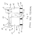
- the prior art food product processing apparatus shown includes a product conveyor 11 and a work unit 13 in the form of an automatic packaging machine.
- the product conveyor 11 comprises a base frame or frame 15 and a conveyor unit 17 fixed to the frame 15.
- the conveyor unit 17 comprises one or more belt or belt conveyors and is laterally cantilevered as shown the frame 15 is arranged.
- the working unit 13 is located below the conveyor unit 17 and also comprises a base frame or a frame 19, which is here composed of cross members 21 with attached thereto, profile-like side members 23.
- a supply and control unit 24 is mounted in the form of a cabinet. Both the product conveyor 11 and the working unit 13 are parked by means of feet 25 on the floor 27.
- the device shown is integrated into a prepackaged food production line and serves to package product slices cut open by a high-performance slicer, not shown, in a batchwise format.
- the product conveyor 11 is accordingly intended to convey delivered product portions in a direction perpendicular to the drawing plane conveying direction and to insert them in an arrangement of provided by the working unit 13 packaging.
- the working unit 13 provides an arrangement of packaging troughs at a transfer section 28 from a provided plastic film web by means of a deep drawing process. After inserting the product portions, the packaging trays are closed with a plastic film web also provided. Above the transfer section 28 is a protective cover 29th
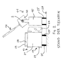
- a housing 30 of the conveyor unit 17 is mounted pivotably on the frame 15 about a pivot axis S. It can thus proceed from the in Fig. 1 illustrated lowered operating position in the in Fig. 2 shown raised maintenance position to be pivoted.
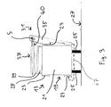
- the product conveyor 31 and the working unit 13 are the product conveyor 31 and the working unit 13 not designed as separate machines, but merged into one unit.
- the frame 35 of the product conveyor 31 is fixed to the work unit 13 at a distance from the stand surface 27, as shown. That is, the product conveyor 31 is completely supported by the process cartridge 13 and supported thereon in both the horizontal and vertical directions.
- the mass and rigidity of the unit of work 13 is sufficient to provide stability to the entire unit.
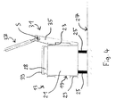
- the conveyor unit 37 of the product conveyor 31 is in the in Fig. 3 to 5 illustrated embodiment of the invention also between a lowered operating position and a raised maintenance position pivoted.
- the conveyor unit 37 is here designed as a tape cassette in which the shafts of the corresponding belt or belt conveyor are mounted. Thus, can be dispensed with a pivotable housing of the conveyor unit 37.
- a protective cover 39 is disposed above the transfer section 28 of the working unit 13. If necessary, however, the protective cover 39 may be fastened or attachable to the underside 40 of the conveyor unit 37 so that it can be pivoted together with the latter between the operating position and the maintenance position (FIG. Fig. 5 ). In case of maintenance, one operation can thus be saved.
- the protective cover 39 is used in the in Fig. 3 to 5 device according to the invention additionally shown as a collecting device for collecting such particles falling from the conveyor unit 37.
- the working unit 13 is also protected from cleaning fluid when, for reasons of hygiene, the product conveyor 31 has to be thoroughly cleaned at regular intervals.
- FIG. 3 A variant of this embodiment is in Fig. 3 indicated by a dashed line.
- this variant is not shown for the sake of simplicity.
- the frame 35 has a designed as a horizontally projecting frame portion arm 67.
- the arm 67 extends from the vertically extending frame portion on the one side of the working unit 13 extends from the bottom of the working unit 13 along the opposite side and is fixed there.
- the working unit 13 is surrounded by the frame 35 in particular like a clip.
- a particularly evenly distributed force introduction over the frame 35 of the product conveyor 31 can be achieved in the working unit 13 in an advantageous manner. Additional feet are not required in this variant.
- the Fig. 6 to 8 show an alternative embodiment of a device according to the invention for processing food products.
- the apparatus also comprises a product conveyor 41 and a working unit 13, but differs from the embodiment described above in that the frame 45 of the product conveyor 41 is formed as a supporting frame.
- the frame 45 of the product conveyor 41 comprises a vertical support portion 47 and a horizontal stand portion 49.
- the frame 45 has a substantially L-shaped cross section.
- the width of the stand portion 49 is greater than the width of the laterally projecting conveyor unit 37, so that a sufficient stability is ensured for the product conveyor 41.
- the stand portion 49 has only a small height, so that it can be arranged in reaching into the free space 60 formed between the feet 25 of the working unit 13.
- the width of the overall apparatus may be greater than that in FIG Fig. 1 and 2 shown arrangement can be reduced. If necessary, the stand section 49 may be attached to the work unit 13 for additional stabilization.
- the conveyor unit 37 designed as a tape cassette and between a lowered operating position ( Fig. 6 ) as well as a raised one Maintenance position ( Fig. 7 and 8th ) pivotable.
- the protective cover 39 may be fastened or attachable to the underside 40 of the conveyor unit 37.
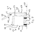
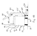
- the frame 55 of the product conveyor 51 is supported both on the bottom 27 and on the working unit 13. Specifically, the frame 55 is attached by means of a connecting element 65 on one of the side support 23, for example, screwed to this. Due to this attachment, the frame 55 need not necessarily be stable, so that it can be designed to be lighter and smaller accordingly. Also at the in Fig. 9 and 10 illustrated embodiment, the conveyor unit 37 is designed as a tape cassette and between a lowered operating position ( Fig. 9 ) and a raised maintenance position ( Fig. 10 ) pivotable. The protective cover 39 can in turn be attached to the underside 40 of the conveyor unit 37, if necessary, which is shown in FIG Fig. 9 and 10 but not shown.
Abstract
Eine Vorrichtung zur Verarbeitung von Lebensmittelprodukten umfasst einen Produktförderer mit einem Rahmen und einer Fördereinheit zum Fördern von Produkten entlang einer Förderrichtung, wobei die Fördereinheit bezüglich der Förderrichtung seitlich auskragend an dem Rahmen angeordnet ist, und eine die Verarbeitung der geförderten Produkte betreffende Arbeitseinheit, die zumindest teilweise unter der auskragenden Fördereinheit des Produktförderers angeordnet ist. Es ist vorgesehen, dass der Rahmen des Produktförderers über eine mechanische Verbindung an der Arbeitseinheit abgestützt oder gehalten ist oder in einen durch die Arbeitseinheit definierten Freiraum hineinreicht.A device for processing food products comprises a product conveyor having a frame and a conveyor unit for conveying products along a conveying direction, wherein the conveyor unit is arranged laterally cantilevering with respect to the conveying direction on the frame, and a working unit relating to the processing of the conveyed products, which at least partially is arranged under the projecting conveyor unit of the product conveyor. It is envisaged that the frame of the product conveyor is supported or held by a mechanical connection to the working unit or extends into a space defined by the working unit.
Description
Die vorliegende Erfindung betrifft eine Vorrichtung zur Verarbeitung von Lebensmittelprodukten, die umfasst:
- einen Produktförderer mit einem Rahmen und einer Fördereinheit zum Fördern von Produkten entlang einer Förderrichtung, wobei die Fördereinheit bezüglich der Förderrichtung seitlich auskragend an dem Rahmen angeordnet ist, und
- eine die Verarbeitung der geförderten Produkte betreffende Arbeitseinheit, die zumindest teilweise unter der auskragenden Fördereinheit des Produktförderers angeordnet ist.
- a product conveyor having a frame and a conveying unit for conveying products along a conveying direction, wherein the conveying unit is arranged with respect to the conveying direction laterally projecting on the frame, and
- a processing unit relating to the processing of the products being conveyed, which is at least partly arranged under the projecting conveyor unit of the product conveyor.
Bei der industriellen Verarbeitung von Lebensmittelprodukten, wie beispielsweise Fleisch-, Wurst- oder Käseprodukten, kommen häufig sogenannte Produktionslinien zum Einsatz, welche neben einer Schneidvorrichtung wie einem Hochleistungsslicer mehrere aneinander gereihte Fördereinrichtungen wie Portionierförderer, Aufreihförderer, Spreizförderer, Verteilerförderer, Pufferförderer und Einlegeförderer umfassen. Am Ende einer solchen Produktionslinie befindet sich üblicherweise eine Verpackungsmaschine, welche aus einer bereitgestellten Kunststofffolienbahn mittels eines Tiefziehprozesses eine Anordnung von Verpackungen zur Verfügung stellt, in welche die Produkte oder Produktportionen mittels eines Einlegeförderers in der Regel formatsatzweise eingelegt werden. Eine solche Verpackungsmaschine mit Tiefzieh-Einheit wird auf dem Fachgebiet auch als "Tiefzieher" bezeichnet. Ebenso wird der Einlegeförderer häufig verkürzt als "Einleger" bezeichnet. Um ein zuverlässiges Einlegen zu ermöglichen, muss der Einleger oberhalb des Tiefziehers positioniert sein, was bei seitlich auskragender Anordnung der Fördereinheit problemlos möglich ist.In the industrial processing of food products, such as meat, sausage or cheese products, so-called production lines are often used, which next to a cutting device such as a high-performance slicer several juxtaposed conveyors such as portioning, Aufreihförderer, spreading conveyor, distribution conveyor, buffer conveyor and infeed conveyor. At the end of such a production line there is usually a packaging machine which, from a provided plastic film web by means of a deep-drawing process, makes available an arrangement of packages in which the products or product portions are usually inserted in formats by means of an infeed conveyor. Such a deep-drawing unit packaging machine is also referred to in the art as a "thermoformer". Likewise, the loading conveyor is often referred to as "depositor" shortened. In order to enable reliable loading, the insert must be positioned above the thermoformer, which is easily possible with laterally projecting arrangement of the conveyor unit.
Unter einer "Vorrichtung zur Verarbeitung von Lebensmittelprodukten" im Sinne der Erfindung soll allgemein eine beliebige Einrichtung zu verstehen sein, welche einer Verarbeitung, Bearbeitung und/oder Handhabung von einzelnen oder portionierten Lebensmittelprodukten dient. Ferner versteht sich, dass eine Anordnung aus einem Produktförderer mit seitlich auskragender Fördereinheit und einer zumindest teilweise unter der Fördereinheit angeordneten Arbeitseinheit in vielfältiger Weise im Umfeld der Lebensmittelbe- und -verarbeitung eingesetzt werden kann, also nicht nur in Form einer Kombination aus Einleger und Tiefzieher. Beispielsweise könnte es sich bei der Arbeitseinheit auch um einen weiteren Produktförderer handeln.A "device for processing food products" in the sense of the invention should generally be understood to mean any device which serves for processing, processing and / or handling of individual or portioned food products. Furthermore, it is understood that an arrangement of a product conveyor with laterally projecting conveyor unit and a at least partially arranged under the conveyor unit working unit can be used in many ways in the environment of food processing and processing, so not only in the form of a combination of depositors and thermoformers. For example, the work unit could also be another product conveyor.
In den meisten praktischen Fällen müssen die Fördereinheiten eines Einlegers für eine formatsatzweise Förderung tauglich sein und daher eine Arbeitsbreite von 40 cm bis 80 cm aufweisen, also relativ stark seitlich auskragen. Die Konstruktion muss ferner ausreichend starr sein, da im Betrieb Schwingungen, die eine ordnungsgemäße Ausrichtung der Produkte oder Portionen beeinträchtigen könnten, nicht akzeptierbar sind. Gleichzeitig muss eine gute Zugänglichkeit aller Maschinenbereiche für Reinigungs- und Wartungsarbeiten gewährleistet sein. Insbesondere das relativ große Tiefziehwerkzeug muss nach oben und zur Seite hin ein - und ausgebaut werden können. Aufgrund der konstruktionsbedingten Kopflastigkeit müssen die Rahmen außerdem im Allgemeinen eine hohe Standfestigkeit aufweisen, weshalb sie dementsprechend schwer sind - häufig bis zu mehreren Tonnen.In most practical cases, the conveyor units of an insert must be suitable for format-rate promotion and therefore have a working width of 40 cm to 80 cm, so project relatively strong laterally. The design must also be sufficiently rigid, as in operation vibrations that could affect proper alignment of the products or portions are unacceptable. At the same time, good accessibility of all machine areas for cleaning and maintenance work must be guaranteed. In particular, the relatively large thermoforming tool must be able to be inserted and removed upwards and sideways. In addition, because of the design-related top-to-bottom strength, the frames generally need to have a high level of stability, which is why they are correspondingly heavy - often up to several tons.
Auf dem Fachgebiet sucht man daher fortlaufend nach Möglichkeiten, Lebensmittelverarbeitungsvorrichtungen kompakter und leichter zu bauen.The art is therefore continually seeking ways to make food processing equipment more compact and lighter.
Die Lösung dieser Aufgabe erfolgt zum einen durch eine Vorrichtung mit den Merkmalen des Anspruchs 1.The solution of this object is achieved on the one hand by a device having the features of claim 1.
Erfindungsgemäß ist der Rahmen des Produktförderers über eine mechanische Verbindung an der Arbeitseinheit abgestützt oder gehalten. Insbesondere ist der Rahmen außerdem an der Arbeitseinheit fixiert. In mechanischer Hinsicht wird also der Produktförderer in die Arbeitseinheit integriert. Somit können die Masse und die Steifigkeit bzw. Stabilität der Arbeitseinheit dazu genutzt werden, dem Rahmen des Produktförderers zusätzliche Standfestigkeit zu verleihen. Im Ergebnis ermöglicht dies eine leichtere und kompaktere Bauweise für den Produktförderer. Die Erfindung beruht unter anderem auf der Erkenntnis, dass es in vielen Anwendungssituationen der vorstehend genannten Art nicht erforderlich ist, die Arbeitseinheit und den Produktförderer als eigenständige standfeste Maschinen auszulegen, da sie ohnehin stets gemeinsam verwendet werden. Demgegenüber ist man auf dem Fachgebiet bislang dem Gedanken verhaftet, beispielsweise für Tiefzieher und Einleger völlig separate Konstruktionen vorzusehen.According to the invention, the frame of the product conveyor is supported or held by a mechanical connection to the working unit. In particular, the frame is also fixed to the work unit. In mechanical terms, therefore, the product conveyor is integrated into the working unit. Thus, the mass and stiffness or stability of the unit of work can be used to add extra stability to the frame of the product conveyor. As a result, this allows for a lighter and more compact design for the product conveyor. Among other things, the invention is based on the recognition that in many application situations of the aforementioned type it is not necessary to design the working unit and the product conveyor as independent, stable machines, since they are always used together in any case. In contrast, the art has hitherto been based on the idea of providing completely separate constructions, for example for thermoformers and inserts.
Die Erfindung betrifft auch eine Vorrichtung zur Verarbeitung von Lebensmittelprodukten, die umfasst:
- einen Produktförderer mit einem als tragendes Gestell ausgebildeten Rahmen und einer Fördereinheit zum Fördern von Produkten entlang einer Förderrichtung, wobei die Fördereinheit bezüglich der Förderrichtung seitlich auskragend an dem Rahmen angeordnet ist, und
- eine die Verarbeitung der geförderten Produkte betreffende Arbeitseinheit, die zumindest teilweise unter der auskragenden Fördereinheit des Produktförderers angeordnet ist.
- a product conveyor having a frame formed as a supporting frame and a conveying unit for conveying products along a conveying direction, wherein the conveying unit is arranged with respect to the conveying direction laterally projecting on the frame, and
- a processing unit relating to the processing of the products being conveyed, which is at least partly arranged under the projecting conveyor unit of the product conveyor.
Gemäß Anspruch 2 ist vorgesehen, dass der Rahmen des Produktförderers zumindest teilweise in einen durch die Arbeitseinheit definierten Freiraum hineinreicht. Der Rahmen kann so eine höhere Stützwirkung entfalten als bei einem Abstellen des Produktförderers neben der Arbeitseinheit. Insbesondere durch ein seitliches Auskragen des Rahmens kann dieser den Freiraum der Arbeitseinheit nutzen.According to claim 2, it is provided that the frame of the product conveyor extends at least partially into a free space defined by the working unit. The frame can thus develop a higher supporting effect than when the product conveyor is parked next to the working unit. In particular, by a lateral protrusion of the frame, this can use the free space of the work unit.
Insgesamt liegt der Erfindung also der allgemeine Gedanke zugrunde, eine unter einem Produktförderer mit seitlich auskragender Fördereinheit anzuordnende Arbeitseinheit dazu zu nutzen, den Produktförderer selbst kompakter und leichter zu bauen. Gemäß den beiden vorstehend genannten Erfindungsaspekten kann die Masse, Steifigkeit oder Stabilität und/oder der umbaute Raum der Arbeitseinheit dazu genutzt werden, die Abstützung des Produktförderers zu verbessern. Hierfür ist es erforderlich, bereits bei der Konstruktion eines Produktförderers die später unter dessen Fördereinheit anzuordnende Arbeitseinheit zu berücksichtigen.Overall, the invention is therefore the general idea to use a to be arranged under a product conveyor with laterally projecting conveyor unit working unit to build the product conveyor itself more compact and easier. According to the two aspects of the invention mentioned above, the mass, rigidity or stability and / or the enclosed space of the working unit can be used to improve the support of the product conveyor. For this purpose, it is necessary to consider the later to be arranged under the conveyor unit working unit already in the construction of a product conveyor.
Vorzugsweise befindet sich der Freiraum im Bereich einer Standfläche und/oder in einem bodennahen Bereich, insbesondere zwischen separaten Standfüßen der Arbeitseinheit. Arbeitseinheiten wie Tiefzieher sind häufig auf Standfüßen abgestellt, zwischen welchen sich ein ausreichender Freiraum zur Aufnahme eines, beispielsweise horizontal verlaufenden, Stützelements des Produktförderers befindet.The free space is preferably located in the area of a standing area and / or in a region near the floor, in particular between separate feet of the working unit. Working units such as thermoformers are often placed on feet, between which there is sufficient space for receiving a, for example, horizontally extending support member of the product conveyor.
Der als tragendes Gestell ausgeführte Rahmen des Produktförderers kann einen neben der Arbeitseinheit angeordneten, insbesondere vertikalen, Tragabschnitt und einen in dem Freiraum hineinreichenden, insbesondere horizontal auskragenden, Standabschnitt aufweisen. Der Rahmen könnte also beispielsweise einen L-förmigen Querschnitt aufweisen. Dies ermöglicht eine besonders kompakte Bauweise, insbesondere bei Verzicht auf einen Standabschnitt auf der der Arbeitseinheit abgewandten Seite des Tragabschnitts. Bei Verwendung eines horizontal verlaufenden Standabschnitts mit geringer Bauhöhe kann auch ein vergleichsweise geringer Freiraum unterhalb der Arbeitseinheit genutzt werden.The designed as a supporting frame frame of the product conveyor may have a arranged next to the work unit, in particular vertical support section and extending into the free space, in particular horizontally projecting, stand section. Thus, the frame could for example have an L-shaped cross-section. This allows a particularly compact construction, in particular in the absence of a stand section on the side facing away from the working unit of the support section. When using a horizontally extending stand section with a low overall height, a comparatively small free space below the working unit can also be used.
Je nach Bedarf kann der Rahmen des Produktförderers in horizontaler und/oder in vertikaler Richtung an der Arbeitseinheit abgestützt sein. Eine Abstützung in horizontaler und in vertikaler Richtung ermöglicht eine besonders hohe Stabilität der Gesamtvorrichtung. Insbesondere ist der Rahmen mit zumindest einem horizontalen Rahmenbereich und/oder mit wenigstens einem vertikalen Rahmenbereich an der Arbeitseinheit abgestützt.Depending on requirements, the frame of the product conveyor may be supported in horizontal and / or vertical direction on the working unit. A support in horizontal and in the vertical direction allows a particularly high stability of the overall device. In particular, the frame is supported with at least one horizontal frame region and / or with at least one vertical frame region on the working unit.
Eine spezielle Ausführungsform der Erfindung sieht vor, dass der Produktförderer vollständig durch die Arbeitseinheit getragen ist. Dies bedeutet eine Abkehr von dem gängigen Prinzip, Produktförderer stets als eigenständige Vorrichtungen zu konstruieren. Letztlich wird bei der genannten Ausgestaltung also eine Arbeitseinheit mit integriertem Produktförderer, also beispielsweise ein Tiefzieher mit einem integrierten Einleger, bereitgestellt.A specific embodiment of the invention provides that the product conveyor is completely carried by the working unit. This is a departure from the common principle of always constructing product conveyors as standalone devices. Ultimately, in the aforementioned embodiment, therefore, a working unit with an integrated product conveyor, that is, for example, a thermoformer with an integrated insert, is provided.
Der Rahmen des Produktförderers kann in Beabstandung von einer Standfläche und/oder vom Boden an der Arbeitseinheit befestigt sein. Das heißt der Produktförderer kann ausschließlich über die Arbeitseinheit auf der Standfläche bzw. am Boden abgestützt sein. Der Verzicht auf eigene Standfüße für den Produktförderer ermöglicht eine beträchtliche Einsparung von Gewicht und Bauraum. Außerdem stellt sich eine Lebensmittelverarbeitungsmaschine mit wenigen Standfüßen als besonders reinigungsfreundlich dar.The frame of the product conveyor may be mounted at a distance from a stand and / or floor at the work unit. This means that the product conveyor can only be supported by the work unit on the stand or on the ground. The absence of own feet for the product conveyor allows a considerable saving of weight and space. In addition, a food processing machine with few feet is particularly easy to clean.
Alternativ kann der Rahmen des Produktförderers sowohl an einer Standfläche und/oder am Boden als auch an der Arbeitseinheit abgestützt sein. Dies ermöglicht eine besonders stabile Gesamtkonstruktion.Alternatively, the frame of the product conveyor may be supported both on a standing surface and / or on the floor as well as on the working unit. This allows a particularly stable overall construction.
Eine bevorzugte Ausgestaltung der Erfindung sieht vor, dass der Rahmen des Produktförderers allein nicht für ein standfestes Tragen der Fördereinheit ausreicht, d.h. dass der Rahmen nur zusammen mit der Arbeitseinheit eine ausreichende Steifigkeit und Standfestigkeit zum Tragen und Betreiben der Fördereinheit bereitstellt. Mit anderen Worten ist der Produktförderer lediglich mit einem leichten Rahmen ausgestattet, um Gewicht, Kosten und Bauraum zu sparen. Die gewünschte Standsicherheit ergibt sich erst durch die Abstützung an der Arbeitseinheit und Ausnutzung von deren Masse und Steifigkeit bzw. Stabilität.A preferred embodiment of the invention provides that the frame of the product conveyor alone is not sufficient for a stable carrying the conveyor unit, ie that the frame provides only together with the working unit sufficient rigidity and stability for carrying and operating the conveyor unit. In other words, the product conveyor is simply equipped with a lightweight frame to save weight, cost and space. The desired stability arises only by the support on the working unit and utilization of their mass and rigidity or stability.
Eine weitere Ausführungsform der Erfindung sieht vor, dass der Rahmen des Produktförderers an einem, insbesondere seitlichen, Halterahmen der Arbeitseinheit fixiert ist. Beispielsweise kann der Rahmen des Produktförderers an einem Rahmen der Arbeitseinheit eingehängt oder angeschraubt sein. Viele Arbeitseinheiten weisen von außen zugängliche Rahmenelemente wie Profilträger auf, die für eine Anbringung des Rahmens des Produktförderers genutzt werden können.A further embodiment of the invention provides that the frame of the product conveyor is fixed to a, in particular lateral, holding frame of the working unit. For example, the frame of the product conveyor may be hung or screwed to a frame of the work unit. Many working units have externally accessible frame members, such as profile beams, which can be used to attach the frame of the product conveyor.
Es kann vorgesehen sein, dass die Fördereinheit des Produktförderers in Bezug auf dessen Rahmen zwischen einer abgesenkten Betriebsstellung und einer angehobenen Wartungsstellung bewegbar ist. Wenn sich die Fördereinheit in der angehobenen Wartungsstellung befindet, ist ein leichter und sicherer Zugang zu der darunter befindlichen Arbeitseinheit gewährleistet, beispielsweise zum Auswechseln eines Tiefziehwerkzeugs. Es ist hierbei nicht erforderlich, den Produktförderer als Ganzes beiseite zu schaffen oder aufwändige Montagearbeiten durchzuführen.It can be provided that the conveying unit of the product conveyor is movable with respect to the frame between a lowered operating position and a raised maintenance position. When the conveyor unit is in the raised service position, it provides easy and safe access to the underlying work unit, for example, to replace a thermoforming tool. It is not necessary here to set aside the product conveyor as a whole or to carry out complex assembly work.
Die Fördereinheit des Produktförderers kann von der Arbeitseinheit, insbesondere durch Verschwenken oder Wegklappen, weg bewegbar sein.The conveying unit of the product conveyor can be moved away from the working unit, in particular by pivoting or folding away.
Zwischen der Fördereinheit des Produktförderers und dem Rahmen kann eine Gelenkverbindung vorgesehen sein, die bei stationärem Rahmen ein Verschwenken oder Wegklappen der Fördereinheit relativ zum Rahmen erlaubt, insbesondere um eine parallel zur Förderrichtung verlaufenden Schwenkachse.Between the conveyor unit of the product conveyor and the frame, a hinge connection may be provided, which allows a pivoting or folding away of the conveyor unit relative to the frame in a stationary frame, in particular about a pivot axis extending parallel to the conveying direction.
Eine weitere Ausgestaltung der Erfindung sieht vor, dass eine Funktionseinheit der Arbeitseinheit gemeinsam mit der Fördereinheit bewegbar ist, wobei, bevorzugt, die Funktionseinheit an einer Unterseite, im unteren Bereich und/der unterhalb der Fördereinheit befestigt ist. Bei der Funktionseinheit kann es sich beispielsweise um eine Schutzabdeckung der Arbeitseinheit handeln, welche im Wartungsfall zu entfernen ist. Dadurch dass eine solche Schutzabdeckung gemeinsam mit der Fördereinheit zum Beispiel zwischen einer Betriebsstellung und einer Wartungsstellung bewegbar ist, entfällt für einen Benutzer das separate Entfernen der Schutzabdeckung. Zudem kann hierdurch in allen Betriebsstellungen dauerhaft gewährleistet werden, dass Produktreste oder Reinigungsmitteltropfen nicht nach unten in den Bereich der Arbeitseinheit gelangen. Die Handhabung der Vorrichtung kann somit vereinfacht und deren Sauberkeit weiter verbessert werden.A further embodiment of the invention provides that a functional unit of the working unit is movable together with the conveyor unit, wherein, preferably, the functional unit on a bottom, in the lower area and / or below the Conveyor unit is attached. The functional unit may be, for example, a protective cover of the working unit, which is to be removed during maintenance. By virtue of the fact that such a protective cover can be moved together with the delivery unit, for example, between an operating position and a maintenance position, it is not necessary for a user to remove the protective cover separately. In addition, this can be permanently ensured in all operating positions that product residues or detergent drops do not reach down into the area of the working unit. The handling of the device can thus be simplified and its cleanliness can be further improved.
Vorzugsweise stellt die Funktionseinheit in einer Betriebsstellung eine Betriebsfunktion der Arbeitseinheit und gleichzeitig eine Betriebsfunktion der Fördereinheit bereit. Beispielsweise kann die Funktionseinheit eine Schutzabdeckung für einen Tiefzieher und gleichzeitig eine Auffangvorrichtung zum Abweisen oder Auffangen von Partikeln bilden, welche von der darüber befindlichen Fördereinheit herabfallen. Demgegenüber ist es bei einer separaten Konstruktion von Tiefzieher und Einleger im Allgemeinen erforderlich, sowohl den Tiefzieher mit einer Schutzabdeckung als auch den Einleger im Bereich unterhalb der Fördereinheit mit einem Auffangblech oder dergleichen zu versehen.In an operating position, the functional unit preferably provides an operating function of the working unit and at the same time an operating function of the conveying unit. For example, the functional unit may form a protective cover for a thermoformer and at the same time a collecting device for deflecting or collecting particles which fall off the conveyor unit above it. In contrast, in a separate construction of thermoformer and insert generally it is necessary to provide both the thermoformer with a protective cover and the insert in the area below the conveyor unit with a collecting plate or the like.
Wie erwähnt kann die Arbeitseinheit eine Einrichtung oder Teile einer Einrichtung zum automatischen Verpacken der geförderten Produkte, beispielsweise einen sogenannten Tiefzieher, umfassen. Grundsätzlich kann die Arbeitseinheit jedoch andere und/oder weitere Einrichtungen zum Be- und Verarbeiten der geförderten Lebensmittelprodukte aufweisen. Der Produktförderer ist vorzugsweise zum Einlegen der geförderten Produkte in jeweilige, durch die Einrichtung zum automatischen Verpacken bereitgestellte Verpackungseinheiten ausgebildet. Eine derart gestaltete Vorrichtung bildet also eine Einheit aus einer Verpackungsmaschine und einem dazugehörigen Einlegeförderer. Derartige Einheiten werden im Umfeld der Lebensmittelverarbeitung häufig benötigt und brauchen erfindungsgemäß aufgrund des modularen Aufbaus aus Produktförderer einerseits und Arbeitseinheit andererseits erst vor Ort direkt am Aufstellort erstellt zu werden. Alternativ oder zusätzlich kann der Produktförderer zum Gruppieren von Produkten oder mehrere Einzelprodukte umfassenden Portionen, zum Bilden von Zeilen aus Produkten oder mehrere Einzelprodukte umfassenden Portionen, und/oder zum Bilden von Formatsätzen aus Produkten oder mehrere Einzelprodukte umfassenden Portionen ausgebildet sein.As mentioned, the working unit may comprise means or parts of means for automatically packaging the conveyed products, for example a so-called thermoformer. In principle, however, the working unit may have other and / or further facilities for processing and processing the subsidized food products. The product conveyor is preferably designed to load the conveyed products into respective packaging units provided by the automatic packaging device. Thus designed device thus forms a unit of a packaging machine and an associated infeed conveyor. Such units are often needed in the field of food processing and need according to the invention due the modular structure of product conveyor on the one hand and work unit on the other hand to be created on site directly on site. Alternatively or additionally, the product conveyor may be configured to group products or individual portions, portions to form rows of products or portions comprising individual products, and / or portions to form portions of products or portions comprising individual products.
Gemäß einem Ausführungsbeispiel ist vorgesehen, dass Positionierungsmittel vorgesehen sind, mittels welcher die Position des Rahmens, insbesondere von horizontalen und/oder vertikalen Rahmenbereichen, relativ zu der Arbeitseinheit, insbesondere bei an der Arbeitseinheit abgestütztem oder gehaltenem Rahmen einstellbar und in einem jeweils eingestellten Zustand gehalten ist, wobei insbesondere die Positionierungsmittel in ihrer einen Abstand zwischen dem Rahmen und der Arbeitseinheit festlegenden Länge veränderlich sind. Hierdurch kann auf denkbar einfache Weise vor Ort eine Adaption des Produktförderers an die Arbeitseinheit bzw. an die jeweils gegebene Abstütz- bzw. Haltesituation vorgenommen werden. Beispielsweise können Elemente oder Teile des Rahmens, beispielsweise horizontal oder vertikal verlaufende Rahmenteile des Produktförderers in der Länge veränderlich sein, um den Produktförderer an die Arbeitseinheit bzw. an deren Mittel zum Abstützen oder Halten bzw. zum Fixieren des Produktförderers anzupassen.According to one embodiment, it is provided that positioning means are provided, by means of which the position of the frame, in particular of horizontal and / or vertical frame regions, relative to the working unit, especially when supported on the work unit or held frame adjustable and held in a set state In particular, the positioning means are variable in their defining a distance between the frame and the working unit length. As a result, an adaptation of the product conveyor to the working unit or to the respectively given supporting or holding situation can be carried out in the simplest possible way on site. For example, elements or parts of the frame, for example horizontally or vertically extending frame parts of the product conveyor, may be variable in length in order to adapt the product conveyor to the working unit or to its means for supporting or holding or fixing the product conveyor.
Des Weiteren kann vorgesehen sein, dass der Rahmen die Arbeitseinheit untergreift oder unterseitig umgreift, wobei insbesondere ein horizontal auskragender Rahmenbereich des Rahmens sich ausgehend von einer Seite der Arbeitseinheit unter dieser hindurch zur gegenüberliegenden Seite erstreckt und an dieser gegenüberliegenden Seite der Arbeitseinheit fixiert ist. Hierdurch kann eine besonders gleichmäßig verteilte Krafteinleitung in den Rahmen der Arbeitseinheit realisiert werden. Zudem können zusätzliche Standfüße für den Produktförderer entfallen, wodurch eine gute Reinigung des Bodens bzw. der Standfläche erleichtert wird.Furthermore, it may be provided that the frame engages below or engages around the working unit, wherein in particular a horizontally projecting frame region of the frame extends from one side of the working unit below it to the opposite side and is fixed on this opposite side of the working unit. In this way, a particularly evenly distributed force introduction into the frame of the working unit can be realized. In addition, additional feet for the product conveyor can be omitted, whereby a good cleaning of the floor or the floor space is facilitated.
Weiterbildungen der Erfindung sind auch in den abhängigen Ansprüchen, der Beschreibung sowie den beigefügten Zeichnungen angegeben.Further developments of the invention are set forth in the dependent claims, the description and the accompanying drawings.
Die Erfindung wird nachfolgend beispielhaft unter Bezugnahme auf die Zeichnungen beschrieben.
- Fig. 1
- zeigt eine gemäß dem Stand der Technik gestaltete Anordnung aus einem Produktförderer und einer Arbeitseinheit, wobei sich eine Fördereinheit des Produktförderers in einer abgesenkten Betriebsstellung befindet.
- Fig. 2
- zeigt die Anordnung gemäß
Fig. 1 , wobei sich die Fördereinheit in einer angehobenen Wartungsstellung befindet. - Fig. 3
- zeigt eine Vorrichtung zur Verarbeitung von Lebensmittelprodukten gemäß einer ersten Ausführungsform der Erfindung, wobei sich eine Fördereinheit eines Produktförderers der Vorrichtung in einer abgesenkten Betriebsstellung befindet.
- Fig. 4
- zeigt die Vorrichtung gemäß
Fig. 3 , wobei sich die Fördereinheit in einer angehobenen Wartungsstellung befindet. - Fig. 5
- zeigt die Vorrichtung gemäß
Fig. 4 , wobei eine Funktionseinheit einer Arbeitseinheit der Vorrichtung gemeinsam mit der Fördereinheit in die angehobene Wartungsstellung bewegt ist. - Fig. 6
- zeigt eine Vorrichtung zur Verarbeitung von Lebensmittelprodukten gemäß einer zweiten Ausführungsform der Erfindung, wobei sich eine Fördereinheit eines Produktförderers der Vorrichtung in einer abgesenkten Betriebsstellung befindet.
- Fig. 7
- zeigt die Vorrichtung gemäß
Fig. 6 , wobei sich die Fördereinheit in einer angehobenen Wartungsstellung befindet. - Fig. 8
- zeigt die Vorrichtung gemäß
Fig. 7 , wobei eine Funktionseinheit einer Arbeitseinheit der Vorrichtung gemeinsam mit der Fördereinheit in die angehobene Wartungsstellung bewegt ist. - Fig. 9
- zeigt eine Vorrichtung zur Verarbeitung von Lebensmittelprodukten gemäß einer dritten Ausführungsform der Erfindung, wobei sich eine Fördereinheit eines Produktförderers der Vorrichtung in einer abgesenkten Betriebsstellung befindet.
- Fig. 10
- zeigt die Vorrichtung gemäß
Fig. 9 , wobei sich die Fördereinheit in einer angehobenen Wartungsstellung befindet.
- Fig. 1
- shows a designed according to the prior art arrangement of a product conveyor and a working unit, wherein a conveyor unit of the product conveyor is in a lowered operating position.
- Fig. 2
- shows the arrangement according to
Fig. 1 , wherein the conveyor unit is in a raised maintenance position. - Fig. 3
- shows a device for processing food products according to a first embodiment of the invention, wherein a conveyor unit of a product conveyor of the device is in a lowered operating position.
- Fig. 4
- shows the device according to
Fig. 3 , wherein the conveyor unit is in a raised maintenance position. - Fig. 5
- shows the device according to
Fig. 4 , wherein a functional unit of a working unit of the device is moved together with the conveyor unit in the raised maintenance position. - Fig. 6
- shows a device for processing food products according to a second embodiment of the invention, wherein a conveyor unit of a product conveyor of the device is in a lowered operating position.
- Fig. 7
- shows the device according to
Fig. 6 , wherein the conveyor unit is in a raised maintenance position. - Fig. 8
- shows the device according to
Fig. 7 , wherein a functional unit of a working unit of the device is moved together with the conveyor unit in the raised maintenance position. - Fig. 9
- shows a device for processing food products according to a third embodiment of the invention, wherein a conveyor unit of a product conveyor of the device is in a lowered operating position.
- Fig. 10
- shows the device according to
Fig. 9 , wherein the conveyor unit is in a raised maintenance position.
Die in
Die in
Um bei Umbau-, Reparatur- oder Wartungsarbeiten einen leichten und sicheren Zugang zu der Arbeitseinheit 13 zu gewährleisten, ist ein Gehäuse 30 der Fördereinheit 17 um eine Schwenkachse S verschwenkbar an dem Rahmen 15 gelagert. Sie kann somit ausgehend von der in
Bei der in
Wie bei der in
Eine Variante dieses Ausführungsbeispiels ist in
Die
Wie bei der in
Bei der in
Durch das Einbeziehen der unter der Fördereinheit 37 anzuordnenden Arbeitseinheit 13 in die Stützkonstruktion des Rahmens 35, 45, 55 des Produktförderers 31, 41, 51 - sei es in Form einer direkten mechanischen Stützverbindung und/oder durch gezielte Nutzung eines durch die Arbeitseinheit 13 definierten Freiraums - kann eine wesentlich leichtere und kompaktere Bauweise für die Verarbeitungsvorrichtung als Ganzes erzielt werden.By including the to be arranged under the
- 1111
- Produktfördererproduct conveyor
- 1313
- Arbeitseinheitwork unit
- 1515
- Rahmen des ProduktförderersFrame of the product conveyor
- 1717
- Fördereinheitdelivery unit
- 1919
- Rahmen der ArbeitseinheitFramework of the work unit
- 2121
- Querträgercrossbeam
- 2323
- Seitenträgerside beams
- 2424
- Versorgungs- und SteuereinheitSupply and control unit
- 2525
- Standfußstand
- 2727
- Standfläche, BodenFloor space, floor
- 2828
- ÜbergabeabschnittTransfer section
- 2929
- Schutzabdeckungprotective cover
- 3030
- Gehäusecasing
- 3131
- Produktfördererproduct conveyor
- 3535
- Rahmen des ProduktförderersFrame of the product conveyor
- 3737
- Fördereinheitdelivery unit
- 3939
- Schutzabdeckungprotective cover
- 4040
- Unterseite der FördereinheitBottom of the conveyor unit
- 4141
- Produktfördererproduct conveyor
- 4545
- Rahmen des ProduktförderersFrame of the product conveyor
- 4747
- Tragabschnittsupporting section
- 4949
- StandabschnittRange section
- 5151
- Produktfördererproduct conveyor
- 5555
- Rahmen des ProduktförderersFrame of the product conveyor
- 6060
- Freiraumfree space
- 6565
- Verbindungselementconnecting element
- 6767
- Rahmenbereich, ArmFrame area, arm
- SS
- Schwenkachseswivel axis
Claims (15)
der Rahmen (35, 55) des Produktförderers (31, 51) über eine mechanische Verbindung an der Arbeitseinheit (13) abgestützt oder gehalten, und insbesondere fixiert, ist.Device for processing food products, comprising:
the frame (35, 55) of the product conveyor (31, 51) is supported or held, and in particular fixed, via a mechanical connection to the working unit (13).
der Rahmen (45) des Produktförderers (41) zumindest teilweise in einen durch die Arbeitseinheit (13) definierten Freiraum (60) hineinreicht.Device for processing food products, comprising:
the frame (45) of the product conveyor (41) extends at least partially into a free space (60) defined by the working unit (13).
dadurch gekennzeichnet, dass
sich der Freiraum (60) im Bereich einer Standfläche (27) befindet, insbesondere zwischen separaten Standfüßen (25) der Arbeitseinheit (13).Device according to claim 2,
characterized in that
the free space (60) is in the area of a standing surface (27), in particular between separate feet (25) of the working unit (13).
dadurch gekennzeichnet, dass
der als tragendes Gestell ausgeführte Rahmen (45) des Produktförderers (41) einen neben der Arbeitseinheit (13) angeordneten, insbesondere vertikalen, Tragabschnitt (47) und einen in den Freiraum (60) hineinreichenden, insbesondere horizontal auskragenden, Standabschnitt (49) aufweist.Device according to claim 2 or 3,
characterized in that
the frame (45) of the product conveyor (41) designed as a load-bearing frame has a support section (47) which is arranged next to the work unit (13) and a stand section (49) extending into the free space (60) and projecting in particular horizontally.
dadurch gekennzeichnet, dass
der Rahmen (35, 55) des Produktförderers (31, 51) in horizontaler und/oder in vertikaler Richtung an der Arbeitseinheit (13) abgestützt ist, wobei insbesondere der Rahmen (35, 55) mit einem horizontalen Rahmenbereich und/oder mit einem vertikalen Rahmenbereich an der Arbeitseinheit (13) fixiert ist.Device according to claim 1,
characterized in that
the frame (35, 55) of the product conveyor (31, 51) is supported horizontally and / or vertically on the work unit (13), in particular the frame (35, 55) having a horizontal frame portion and / or a vertical frame Frame is fixed to the working unit (13).
dadurch gekennzeichnet, dass
der Produktförderer (31) vollständig durch die Arbeitseinheit (13) getragen ist, wobei insbesondere der Rahmen (35) des Produktförderers (31) in Beabstandung von einer Standfläche (27) an der Arbeitseinheit (13) befestigt ist.Device according to claim 1 or 5,
characterized in that
the product conveyor (31) is fully supported by the work unit (13), in particular the frame (35) of the product conveyor (31) being spaced from a standing surface (27) on the work unit (13).
dadurch gekennzeichnet, dass
der Rahmen (55) des Produktförderers (51) sowohl an einer Standfläche (27) als auch an der Arbeitseinheit (13) abgestützt ist, wobei insbesonderedass der Rahmen (55) des Produktförderers (51) nur zusammen mit der Arbeitseinheit (13) eine ausreichende Steifigkeit und Standfestigkeit zum Tragen und Betreiben der Fördereinheit (37) bereitstellt.Device according to claim 1 or 5,
characterized in that
the frame (55) of the product conveyor (51) is supported both on a standing surface (27) and on the working unit (13), in particular that the frame (55) of the product conveyor (51) only together with the working unit (13) Provides rigidity and stability for carrying and operating the conveyor unit (37).
dadurch gekennzeichnet, dass
der Rahmen (35, 55) des Produktförderers (31, 51) an einem, insbesondere seitlichen, Halterahmen (23) der Arbeitseinheit (13) fixiert ist, und/oder dass die Fördereinheit (37) des Produktförderers (31, 41, 51) in Bezug auf dessen Rahmen (35, 45, 55) zwischen einer abgesenkten Betriebsstellung und einer angehobenen Wartungsstellung bewegbar ist.Device according to one of the preceding claims,
characterized in that
the frame (35, 55) of the product conveyor (31, 51) is fixed to a, in particular lateral, holding frame (23) of the working unit (13), and / or that the conveying unit (37) of the product conveyor (31, 41, 51) with respect to the frame (35, 45, 55) between a lowered operating position and a raised maintenance position is movable.
dadurch gekennzeichnet, dass
die Fördereinheit (37) des Produktförderers (31, 41, 51) von der Arbeitseinheit (13), insbesondere durch Verschwenken oder Wegklappen, weg bewegbar ist.Device according to one of the preceding claims,
characterized in that
the conveyor unit (37) of the product conveyor (31, 41, 51) of the working unit (13), in particular by pivoting or folding away, is movable away.
dadurch gekennzeichnet, dass
zwischen der Fördereinheit (37) des Produktförderers (31, 41, 51) und dem Rahmen (35, 45, 55) eine Gelenkverbindung vorgesehen ist, die bei stationärem Rahmen (35, 45, 55) ein Verschwenken oder Wegklappen der Fördereinheit (37) relativ zum Rahmen (35, 45, 55) erlaubt, insbesondere um eine parallel zur Förderrichtung verlaufenden Schwenkachse (S).Device according to one of the preceding claims,
characterized in that
between the conveyor unit (37) of the product conveyor (31, 41, 51) and the frame (35, 45, 55) is provided a hinge connection, the stationary unit (35, 45, 55) pivoting or folding away the conveyor unit (37) relative to the frame (35, 45, 55) allowed, in particular to a parallel to the conveying direction pivot axis (S).
dadurch gekennzeichnet, dass
eine Funktionseinheit (39) der Arbeitseinheit (13) gemeinsam mit der Fördereinheit (13) bewegbar ist, wobei, bevorzugt, die Funktionseinheit (39) an einer Unterseite (40), im unteren Bereich und/oder unterhalb der Fördereinheit (37) fixiert ist, und/oder dass die Funktionseinheit (39) in einer Betriebsstellung eine Betriebsfunktion der Arbeitseinheit (13) und gleichzeitig eine Betriebsfunktion der Fördereinheit (37) bereitstellt.Device according to one of claims 8 to 10,
characterized in that
a functional unit (39) of the working unit (13) is movable together with the conveying unit (13), wherein, preferably, the functional unit (39) is fixed to a lower side (40), in the lower region and / or below the conveying unit (37) , and / or that the functional unit (39) in an operating position provides an operating function of the working unit (13) and at the same time an operating function of the conveyor unit (37).
dadurch gekennzeichnet, dass
die Arbeitseinheit (13) eine Einrichtung oder Teile einer Einrichtung zum automatischen Verpacken der geförderten Produkte umfasst, und/oder dass die Arbeitseinheit (13) als Tiefzieheinrichtung oder als ein Bestandteil einer Tiefzieheinrichtung ausgebildet ist.Device according to one of the preceding claims,
characterized in that
the working unit (13) comprises a device or parts of a device for automatically packaging the conveyed products, and / or that the working unit (13) is designed as a deep drawing device or as part of a deep drawing device.
dadurch gekennzeichnet, dass
der Produktförderer (31, 41, 51) zum Einlegen der geförderten Produkte in jeweilige, durch die Einrichtung zum automatischen Verpacken bereitgestellte Verpackungseinheiten, zum Gruppieren von Produkten oder mehrere Einzelprodukte umfassenden Portionen, zum Bilden von Zeilen aus Produkten oder mehrere Einzelprodukte umfassenden Portionen und/oder zum Bilden von Formatsätzen aus Produkten oder mehrere Einzelprodukte umfassenden Portionen, ausgebildet ist.Device according to one of the preceding claims,
characterized in that
the product conveyor (31, 41, 51) for loading the conveyed products into respective packaging units provided by the automatic packaging device, grouping products or multiple individual product portions, forming portions of products or multiple individual product portions, and / or for forming format sets of products or portions comprising several individual products is formed.
dadurch gekennzeichnet, dass
Positionierungsmittel vorgesehen sind, mittels welcher die Position des Rahmens (35, 45, 55), insbesondere von horizontalen und/oder vertikalen Rahmenbereichen, relativ zu der Arbeitseinheit (13), insbesondere bei an der Arbeitseinheit (13) abgestütztem oder gehaltenem Rahmen (35, 45, 55), einstellbar und in einem jeweils eingestellten Zustand gehalten ist, wobei insbesondere die Positionierungsmittel in ihrer einen Abstand zwischen dem Rahmen (35, 45, 55) und der Arbeitseinheit (13) festlegenden Länge veränderlich sind.Device according to one of the preceding claims,
characterized in that
Positioning means are provided, by means of which the position of the frame (35, 45, 55), in particular of horizontal and / or vertical frame regions, relative to the working unit (13), in particular supported on the working unit (13) or held frame (35, 45, 55), is adjustable and held in a respectively set state, in particular, the positioning means in their a distance between the frame (35, 45, 55) and the working unit (13) defining length are variable.
dadurch gekennzeichnet, dass
der Rahmen (35) die Arbeitseinheit (13) untergreift oder unterseitig umgreift, wobei insbesondere ein horizontal auskragender Rahmenbereich (67) des Rahmens (35) sich ausgehend von einer Seite der Arbeitseinheit (13) unter dieser hindurch zur gegenüberliegenden Seite erstreckt und an dieser gegenüberliegenden Seite der Arbeitseinheit (13) fixiert ist.Device according to one of the preceding claims,
characterized in that
the frame (35) engages under or engages around the working unit (13), wherein in particular a horizontally projecting frame region (67) of the frame (35) extends from one side of the working unit (13) to the opposite side and opposite thereto Side of the working unit (13) is fixed.
Priority Applications (1)
| Application Number | Priority Date | Filing Date | Title |
|---|---|---|---|
| PL15161101.9T PL2923955T5 (en) | 2014-03-28 | 2015-03-26 | Device for processing food products |
Applications Claiming Priority (1)
| Application Number | Priority Date | Filing Date | Title |
|---|---|---|---|
| DE102014104387.1A DE102014104387A1 (en) | 2014-03-28 | 2014-03-28 | Device for processing food products |
Publications (4)
| Publication Number | Publication Date |
|---|---|
| EP2923955A2 true EP2923955A2 (en) | 2015-09-30 |
| EP2923955A3 EP2923955A3 (en) | 2015-12-09 |
| EP2923955B1 EP2923955B1 (en) | 2016-10-19 |
| EP2923955B2 EP2923955B2 (en) | 2022-11-30 |
Family
ID=52780880
Family Applications (1)
| Application Number | Title | Priority Date | Filing Date |
|---|---|---|---|
| EP15161101.9A Active EP2923955B2 (en) | 2014-03-28 | 2015-03-26 | Device for processing food products |
Country Status (5)
| Country | Link |
|---|---|
| US (2) | US11383935B2 (en) |
| EP (1) | EP2923955B2 (en) |
| DE (1) | DE102014104387A1 (en) |
| ES (1) | ES2611578T5 (en) |
| PL (1) | PL2923955T5 (en) |
Cited By (2)
| Publication number | Priority date | Publication date | Assignee | Title |
|---|---|---|---|---|
| EP3381820A1 (en) * | 2017-03-30 | 2018-10-03 | MULTIVAC Sepp Haggenmüller SE & Co. KG | Packaging machine with stackable safety covers |
| EP3476774A1 (en) * | 2017-10-26 | 2019-05-01 | Weber Maschinenbau GmbH Breidenbach | Transport device |
Families Citing this family (1)
| Publication number | Priority date | Publication date | Assignee | Title |
|---|---|---|---|---|
| DE102017108991A1 (en) | 2017-04-26 | 2018-10-31 | Weber Maschinenbau Gmbh Breidenbach | PACKAGING FOOD PRODUCTS |
Family Cites Families (30)
| Publication number | Priority date | Publication date | Assignee | Title |
|---|---|---|---|---|
| US3561512A (en) * | 1968-04-15 | 1971-02-09 | Ward Foods Inc | Pineapple-treating apparatus |
| GB1512509A (en) * | 1974-05-23 | 1978-06-01 | Shell Bv | Fungicides |
| US4034536A (en) | 1976-06-11 | 1977-07-12 | Mahaffy & Harder Engineering Company | Packaging apparatus and techniques |
| US4548108A (en) * | 1983-08-08 | 1985-10-22 | Cashin Systems Corporation | Slicing machine |
| WO1990011881A1 (en) * | 1989-04-07 | 1990-10-18 | Hitek Limited | Continuous feed thermoforming method and apparatus |
| GB2241682B (en) | 1990-03-05 | 1993-11-03 | Arnott Handling Equipment Limi | Conveyor assembly |
| US5271304A (en) * | 1990-07-03 | 1993-12-21 | Carruthers Equipment Co. | Automatic food slicing machine |
| CH683176A5 (en) | 1991-04-25 | 1994-01-31 | Buehler S A R L | Conveyor band for transporting of goods - has support system on one side of frame which is made up of two spaced parallel girders and two U=shaped brackets |
| CA2133953A1 (en) * | 1992-04-23 | 1993-11-11 | Joseph Carey | Meat slicing machine and method of use thereof |
| DE4218720A1 (en) * | 1992-06-06 | 1993-12-09 | Bielomatik Leuze & Co | Closing device for wrappings |
| DE4334238A1 (en) * | 1993-10-04 | 1995-04-06 | Stimpfl Christof | Device for packaging objects |
| US5444750A (en) * | 1993-11-09 | 1995-08-22 | Bass Gambling Supplies Inc. | Tally punch machine |
| DE4407639A1 (en) | 1994-03-08 | 1995-09-14 | Tetra Laval Convenience Food | Method and deep-drawing device for producing a film tray |
| AU691276B2 (en) * | 1994-05-03 | 1998-05-14 | Inauen Maschinen Ag | Vacuum packaging machine |
| US5499719A (en) * | 1995-02-13 | 1996-03-19 | Formax, Inc. | Takeaway/correction conveyor system for food product machine |
| DE29718630U1 (en) * | 1997-10-21 | 1997-12-11 | Ruehle Gmbh | Cube and strip cutting machine |
| FR2771080B1 (en) | 1997-11-18 | 2000-01-28 | Sogem Agro | MOTORIZED ENDLESS BELT CONVEYOR |
| DE29801161U1 (en) * | 1998-01-24 | 1998-03-05 | Magurit Gefrierschneider Gmbh | Shredder for food |
| FR2821833A1 (en) | 2001-03-06 | 2002-09-13 | Bernard Jean Michel Philippe | Belt conveyor esp for packaging food products has lower supporting frame of welded round tubes and articulated sliding panel |
| US6585477B1 (en) * | 2001-06-22 | 2003-07-01 | Lawrence Equipment | Counter-stacker for flat food products |
| DE10143506A1 (en) | 2001-09-05 | 2003-05-08 | Weber Maschb Gmbh & Co Kg | distribution device |
| DE10201182A1 (en) | 2002-01-14 | 2003-07-24 | Cfs Gmbh Kempten | positioning |
| DE10238482A1 (en) * | 2002-05-23 | 2003-12-04 | Cfs Kempten Gmbh | Insertion appliance for packaging machine has conveyor with fixed and swivel parts, horizontal or vertical swivel axle, conveyor belts and drive mechanism |
| DE102006020368A1 (en) | 2006-02-09 | 2007-08-16 | Cfs Germany Gmbh | Packaging machine with a chain cleaning |
| DE102006006523A1 (en) | 2006-02-10 | 2007-08-16 | Cfs Germany Gmbh | Packaging machine, particularly form filling seal packaging machine, has transport medium arranged in multiple rows and clamping mediums of chain are tilted around horizontally aligned axis |
| FR2900858B1 (en) | 2006-05-12 | 2008-06-27 | Ermatec Sarl | CUTTING MACHINE FOR AGRO-FOOD PRODUCTS AND PACKAGING MACHINE THEREFOR |
| DE102008015689A1 (en) * | 2008-03-26 | 2009-10-01 | Multivac Sepp Haggenmüller Gmbh & Co. Kg | packaging machine |
| DE102010034676A1 (en) | 2010-08-18 | 2012-02-23 | Weber Maschinenbau Gmbh Breidenbach | Conveying objects |
| IT1404664B1 (en) * | 2010-12-22 | 2013-11-29 | Grasselli | EQUIPMENT FOR DEPOSITION IN SLICED FOOD CONTAINERS |
| DE102011101101A1 (en) * | 2011-05-10 | 2014-01-30 | Bizerba Gmbh & Co Kg | cutting machine |
-
2014
- 2014-03-28 DE DE102014104387.1A patent/DE102014104387A1/en active Pending
-
2015
- 2015-03-26 US US14/669,548 patent/US11383935B2/en active Active
- 2015-03-26 EP EP15161101.9A patent/EP2923955B2/en active Active
- 2015-03-26 ES ES15161101T patent/ES2611578T5/en active Active
- 2015-03-26 PL PL15161101.9T patent/PL2923955T5/en unknown
-
2022
- 2022-02-04 US US17/665,029 patent/US20220153527A1/en active Pending
Non-Patent Citations (1)
| Title |
|---|
| None |
Cited By (5)
| Publication number | Priority date | Publication date | Assignee | Title |
|---|---|---|---|---|
| EP3381820A1 (en) * | 2017-03-30 | 2018-10-03 | MULTIVAC Sepp Haggenmüller SE & Co. KG | Packaging machine with stackable safety covers |
| US10899486B2 (en) | 2017-03-30 | 2021-01-26 | Multivac Sepp Haggenmüller Se & Co. Kg | Packaging machine with stackable protective covers |
| EP3476774A1 (en) * | 2017-10-26 | 2019-05-01 | Weber Maschinenbau GmbH Breidenbach | Transport device |
| US10717609B2 (en) | 2017-10-26 | 2020-07-21 | Weber Maschinenbau Breidenbach GmbH | Conveying device |
| EP3476774B1 (en) | 2017-10-26 | 2022-12-07 | Weber Maschinenbau GmbH Breidenbach | Transport device |
Also Published As
| Publication number | Publication date |
|---|---|
| US11383935B2 (en) | 2022-07-12 |
| EP2923955A3 (en) | 2015-12-09 |
| DE102014104387A1 (en) | 2015-10-01 |
| US20150274431A1 (en) | 2015-10-01 |
| ES2611578T5 (en) | 2023-02-17 |
| EP2923955B2 (en) | 2022-11-30 |
| PL2923955T5 (en) | 2023-03-27 |
| EP2923955B1 (en) | 2016-10-19 |
| ES2611578T3 (en) | 2017-05-09 |
| US20220153527A1 (en) | 2022-05-19 |
| PL2923955T3 (en) | 2017-05-31 |
Similar Documents
| Publication | Publication Date | Title |
|---|---|---|
| EP3476774B1 (en) | Transport device | |
| EP2794433B1 (en) | Picking system and method for picking articles | |
| EP3233639A1 (en) | Device for moving objects | |
| EP2527262B1 (en) | Apparatus for filling containers | |
| EP3315423B1 (en) | Deep draw packaging machine | |
| EP3315420B1 (en) | Deep draw packaging machine | |
| EP2923955B1 (en) | Device for processing food products | |
| EP3009379B1 (en) | Conveying device with an extended conveying body | |
| EP3025971B1 (en) | Filling and changing device for filling containers with bulk material | |
| DE102014106740A1 (en) | Device for conveying food products | |
| DE102013100806B4 (en) | Multi-lane conveyor | |
| DE102015210052A1 (en) | Transfer device and method | |
| DE102018204035A1 (en) | BELT CONVEYOR WITH WIPER ASSEMBLY | |
| EP4281397A1 (en) | Conveyor system for conveying goods to be conveyed | |
| EP3699118B1 (en) | Feeding device for container parts for use on a device for filling containers with liquid to pasty foodstuffs | |
| DE102008043815A1 (en) | Container for transporting e.g. external wall part for construction of housing of refrigerator, has separating element movable between left stop and intermediate positions, if other separating element is in corresponding left stop position | |
| EP3066035B1 (en) | Scales with a foldable weighing table | |
| EP3395696B1 (en) | Packaging of food products | |
| DE102005019948B4 (en) | Machine frame for a bread slicer | |
| DE10134602B4 (en) | Belt conveyor for general cargo | |
| EP3428079B1 (en) | Deep draw packaging machine with flexible package support | |
| EP2594489B1 (en) | Packaging machine | |
| EP3334284B1 (en) | Foodstuff-conveying and -discharging apparatus | |
| EP2938975B1 (en) | Frame of a weighing/conveying device | |
| DE102004044846B4 (en) | Plant for filling |
Legal Events
| Date | Code | Title | Description |
|---|---|---|---|
| PUAI | Public reference made under article 153(3) epc to a published international application that has entered the european phase |
Free format text: ORIGINAL CODE: 0009012 |
|
| AK | Designated contracting states |
Kind code of ref document: A2 Designated state(s): AL AT BE BG CH CY CZ DE DK EE ES FI FR GB GR HR HU IE IS IT LI LT LU LV MC MK MT NL NO PL PT RO RS SE SI SK SM TR |
|
| AX | Request for extension of the european patent |
Extension state: BA ME |
|
| PUAL | Search report despatched |
Free format text: ORIGINAL CODE: 0009013 |
|
| AK | Designated contracting states |
Kind code of ref document: A3 Designated state(s): AL AT BE BG CH CY CZ DE DK EE ES FI FR GB GR HR HU IE IS IT LI LT LU LV MC MK MT NL NO PL PT RO RS SE SI SK SM TR |
|
| AX | Request for extension of the european patent |
Extension state: BA ME |
|
| RIC1 | Information provided on ipc code assigned before grant |
Ipc: B65B 9/04 20060101ALI20151030BHEP Ipc: B65B 35/24 20060101AFI20151030BHEP |
|
| 17P | Request for examination filed |
Effective date: 20160113 |
|
| RBV | Designated contracting states (corrected) |
Designated state(s): AL AT BE BG CH CY CZ DE DK EE ES FI FR GB GR HR HU IE IS IT LI LT LU LV MC MK MT NL NO PL PT RO RS SE SI SK SM TR |
|
| GRAP | Despatch of communication of intention to grant a patent |
Free format text: ORIGINAL CODE: EPIDOSNIGR1 |
|
| RIC1 | Information provided on ipc code assigned before grant |
Ipc: B65G 47/26 20060101ALI20160413BHEP Ipc: B29C 51/26 20060101ALI20160413BHEP Ipc: B65G 35/00 20060101ALI20160413BHEP Ipc: B65B 9/04 20060101ALI20160413BHEP Ipc: B65B 35/24 20060101AFI20160413BHEP Ipc: B65B 59/00 20060101ALI20160413BHEP |
|
| INTG | Intention to grant announced |
Effective date: 20160502 |
|
| GRAS | Grant fee paid |
Free format text: ORIGINAL CODE: EPIDOSNIGR3 |
|
| GRAA | (expected) grant |
Free format text: ORIGINAL CODE: 0009210 |
|
| STAA | Information on the status of an ep patent application or granted ep patent |
Free format text: STATUS: THE PATENT HAS BEEN GRANTED |
|
| AK | Designated contracting states |
Kind code of ref document: B1 Designated state(s): AL AT BE BG CH CY CZ DE DK EE ES FI FR GB GR HR HU IE IS IT LI LT LU LV MC MK MT NL NO PL PT RO RS SE SI SK SM TR |
|
| REG | Reference to a national code |
Ref country code: GB Ref legal event code: FG4D Free format text: NOT ENGLISH |
|
| REG | Reference to a national code |
Ref country code: CH Ref legal event code: EP |
|
| REG | Reference to a national code |
Ref country code: AT Ref legal event code: REF Ref document number: 838089 Country of ref document: AT Kind code of ref document: T Effective date: 20161115 |
|
| REG | Reference to a national code |
Ref country code: IE Ref legal event code: FG4D Free format text: LANGUAGE OF EP DOCUMENT: GERMAN |
|
| REG | Reference to a national code |
Ref country code: DE Ref legal event code: R096 Ref document number: 502015000241 Country of ref document: DE |
|
| REG | Reference to a national code |
Ref country code: NL Ref legal event code: FP |
|
| REG | Reference to a national code |
Ref country code: LT Ref legal event code: MG4D |
|
| PG25 | Lapsed in a contracting state [announced via postgrant information from national office to epo] |
Ref country code: LV Free format text: LAPSE BECAUSE OF FAILURE TO SUBMIT A TRANSLATION OF THE DESCRIPTION OR TO PAY THE FEE WITHIN THE PRESCRIBED TIME-LIMIT Effective date: 20161019 |
|
| REG | Reference to a national code |
Ref country code: FR Ref legal event code: PLFP Year of fee payment: 3 |
|
| PG25 | Lapsed in a contracting state [announced via postgrant information from national office to epo] |
Ref country code: LT Free format text: LAPSE BECAUSE OF FAILURE TO SUBMIT A TRANSLATION OF THE DESCRIPTION OR TO PAY THE FEE WITHIN THE PRESCRIBED TIME-LIMIT Effective date: 20161019 Ref country code: NO Free format text: LAPSE BECAUSE OF FAILURE TO SUBMIT A TRANSLATION OF THE DESCRIPTION OR TO PAY THE FEE WITHIN THE PRESCRIBED TIME-LIMIT Effective date: 20170119 Ref country code: GR Free format text: LAPSE BECAUSE OF FAILURE TO SUBMIT A TRANSLATION OF THE DESCRIPTION OR TO PAY THE FEE WITHIN THE PRESCRIBED TIME-LIMIT Effective date: 20170120 Ref country code: SE Free format text: LAPSE BECAUSE OF FAILURE TO SUBMIT A TRANSLATION OF THE DESCRIPTION OR TO PAY THE FEE WITHIN THE PRESCRIBED TIME-LIMIT Effective date: 20161019 |
|
| REG | Reference to a national code |
Ref country code: ES Ref legal event code: FG2A Ref document number: 2611578 Country of ref document: ES Kind code of ref document: T3 Effective date: 20170509 |
|
| PG25 | Lapsed in a contracting state [announced via postgrant information from national office to epo] |
Ref country code: RS Free format text: LAPSE BECAUSE OF FAILURE TO SUBMIT A TRANSLATION OF THE DESCRIPTION OR TO PAY THE FEE WITHIN THE PRESCRIBED TIME-LIMIT Effective date: 20161019 Ref country code: PT Free format text: LAPSE BECAUSE OF FAILURE TO SUBMIT A TRANSLATION OF THE DESCRIPTION OR TO PAY THE FEE WITHIN THE PRESCRIBED TIME-LIMIT Effective date: 20170220 Ref country code: FI Free format text: LAPSE BECAUSE OF FAILURE TO SUBMIT A TRANSLATION OF THE DESCRIPTION OR TO PAY THE FEE WITHIN THE PRESCRIBED TIME-LIMIT Effective date: 20161019 Ref country code: IS Free format text: LAPSE BECAUSE OF FAILURE TO SUBMIT A TRANSLATION OF THE DESCRIPTION OR TO PAY THE FEE WITHIN THE PRESCRIBED TIME-LIMIT Effective date: 20170219 Ref country code: HR Free format text: LAPSE BECAUSE OF FAILURE TO SUBMIT A TRANSLATION OF THE DESCRIPTION OR TO PAY THE FEE WITHIN THE PRESCRIBED TIME-LIMIT Effective date: 20161019 |
|
| REG | Reference to a national code |
Ref country code: DE Ref legal event code: R026 Ref document number: 502015000241 Country of ref document: DE |
|
| PLBI | Opposition filed |
Free format text: ORIGINAL CODE: 0009260 |
|
| PG25 | Lapsed in a contracting state [announced via postgrant information from national office to epo] |
Ref country code: DK Free format text: LAPSE BECAUSE OF FAILURE TO SUBMIT A TRANSLATION OF THE DESCRIPTION OR TO PAY THE FEE WITHIN THE PRESCRIBED TIME-LIMIT Effective date: 20161019 Ref country code: CZ Free format text: LAPSE BECAUSE OF FAILURE TO SUBMIT A TRANSLATION OF THE DESCRIPTION OR TO PAY THE FEE WITHIN THE PRESCRIBED TIME-LIMIT Effective date: 20161019 Ref country code: SK Free format text: LAPSE BECAUSE OF FAILURE TO SUBMIT A TRANSLATION OF THE DESCRIPTION OR TO PAY THE FEE WITHIN THE PRESCRIBED TIME-LIMIT Effective date: 20161019 Ref country code: RO Free format text: LAPSE BECAUSE OF FAILURE TO SUBMIT A TRANSLATION OF THE DESCRIPTION OR TO PAY THE FEE WITHIN THE PRESCRIBED TIME-LIMIT Effective date: 20161019 Ref country code: EE Free format text: LAPSE BECAUSE OF FAILURE TO SUBMIT A TRANSLATION OF THE DESCRIPTION OR TO PAY THE FEE WITHIN THE PRESCRIBED TIME-LIMIT Effective date: 20161019 |
|
| PLAX | Notice of opposition and request to file observation + time limit sent |
Free format text: ORIGINAL CODE: EPIDOSNOBS2 |
|
| 26 | Opposition filed |
Opponent name: FORMAX, INC. Effective date: 20170717 |
|
| PG25 | Lapsed in a contracting state [announced via postgrant information from national office to epo] |
Ref country code: BG Free format text: LAPSE BECAUSE OF FAILURE TO SUBMIT A TRANSLATION OF THE DESCRIPTION OR TO PAY THE FEE WITHIN THE PRESCRIBED TIME-LIMIT Effective date: 20170119 Ref country code: SM Free format text: LAPSE BECAUSE OF FAILURE TO SUBMIT A TRANSLATION OF THE DESCRIPTION OR TO PAY THE FEE WITHIN THE PRESCRIBED TIME-LIMIT Effective date: 20161019 |
|
| PG25 | Lapsed in a contracting state [announced via postgrant information from national office to epo] |
Ref country code: SI Free format text: LAPSE BECAUSE OF FAILURE TO SUBMIT A TRANSLATION OF THE DESCRIPTION OR TO PAY THE FEE WITHIN THE PRESCRIBED TIME-LIMIT Effective date: 20161019 Ref country code: MC Free format text: LAPSE BECAUSE OF FAILURE TO SUBMIT A TRANSLATION OF THE DESCRIPTION OR TO PAY THE FEE WITHIN THE PRESCRIBED TIME-LIMIT Effective date: 20161019 |
|
| REG | Reference to a national code |
Ref country code: IE Ref legal event code: MM4A |
|
| PG25 | Lapsed in a contracting state [announced via postgrant information from national office to epo] |
Ref country code: LU Free format text: LAPSE BECAUSE OF NON-PAYMENT OF DUE FEES Effective date: 20170326 |
|
| PG25 | Lapsed in a contracting state [announced via postgrant information from national office to epo] |
Ref country code: IE Free format text: LAPSE BECAUSE OF NON-PAYMENT OF DUE FEES Effective date: 20170326 |
|
| REG | Reference to a national code |
Ref country code: BE Ref legal event code: MM Effective date: 20170331 |
|
| REG | Reference to a national code |
Ref country code: FR Ref legal event code: PLFP Year of fee payment: 4 |
|
| PG25 | Lapsed in a contracting state [announced via postgrant information from national office to epo] |
Ref country code: BE Free format text: LAPSE BECAUSE OF NON-PAYMENT OF DUE FEES Effective date: 20170331 |
|
| PG25 | Lapsed in a contracting state [announced via postgrant information from national office to epo] |
Ref country code: MT Free format text: LAPSE BECAUSE OF FAILURE TO SUBMIT A TRANSLATION OF THE DESCRIPTION OR TO PAY THE FEE WITHIN THE PRESCRIBED TIME-LIMIT Effective date: 20161019 |
|
| REG | Reference to a national code |
Ref country code: CH Ref legal event code: PL |
|
| PG25 | Lapsed in a contracting state [announced via postgrant information from national office to epo] |
Ref country code: CH Free format text: LAPSE BECAUSE OF NON-PAYMENT OF DUE FEES Effective date: 20180331 Ref country code: LI Free format text: LAPSE BECAUSE OF NON-PAYMENT OF DUE FEES Effective date: 20180331 |
|
| PLBB | Reply of patent proprietor to notice(s) of opposition received |
Free format text: ORIGINAL CODE: EPIDOSNOBS3 |
|
| APBM | Appeal reference recorded |
Free format text: ORIGINAL CODE: EPIDOSNREFNO |
|
| APBP | Date of receipt of notice of appeal recorded |
Free format text: ORIGINAL CODE: EPIDOSNNOA2O |
|
| APAH | Appeal reference modified |
Free format text: ORIGINAL CODE: EPIDOSCREFNO |
|
| APBM | Appeal reference recorded |
Free format text: ORIGINAL CODE: EPIDOSNREFNO |
|
| APBP | Date of receipt of notice of appeal recorded |
Free format text: ORIGINAL CODE: EPIDOSNNOA2O |
|
| PG25 | Lapsed in a contracting state [announced via postgrant information from national office to epo] |
Ref country code: HU Free format text: LAPSE BECAUSE OF FAILURE TO SUBMIT A TRANSLATION OF THE DESCRIPTION OR TO PAY THE FEE WITHIN THE PRESCRIBED TIME-LIMIT; INVALID AB INITIO Effective date: 20150326 |
|
| APBQ | Date of receipt of statement of grounds of appeal recorded |
Free format text: ORIGINAL CODE: EPIDOSNNOA3O |
|
| APBQ | Date of receipt of statement of grounds of appeal recorded |
Free format text: ORIGINAL CODE: EPIDOSNNOA3O |
|
| PG25 | Lapsed in a contracting state [announced via postgrant information from national office to epo] |
Ref country code: CY Free format text: LAPSE BECAUSE OF FAILURE TO SUBMIT A TRANSLATION OF THE DESCRIPTION OR TO PAY THE FEE WITHIN THE PRESCRIBED TIME-LIMIT Effective date: 20161019 |
|
| PG25 | Lapsed in a contracting state [announced via postgrant information from national office to epo] |
Ref country code: MK Free format text: LAPSE BECAUSE OF FAILURE TO SUBMIT A TRANSLATION OF THE DESCRIPTION OR TO PAY THE FEE WITHIN THE PRESCRIBED TIME-LIMIT Effective date: 20161019 |
|
| PG25 | Lapsed in a contracting state [announced via postgrant information from national office to epo] |
Ref country code: TR Free format text: LAPSE BECAUSE OF FAILURE TO SUBMIT A TRANSLATION OF THE DESCRIPTION OR TO PAY THE FEE WITHIN THE PRESCRIBED TIME-LIMIT Effective date: 20161019 |
|
| PG25 | Lapsed in a contracting state [announced via postgrant information from national office to epo] |
Ref country code: AL Free format text: LAPSE BECAUSE OF FAILURE TO SUBMIT A TRANSLATION OF THE DESCRIPTION OR TO PAY THE FEE WITHIN THE PRESCRIBED TIME-LIMIT Effective date: 20161019 |
|
| REG | Reference to a national code |
Ref country code: AT Ref legal event code: MM01 Ref document number: 838089 Country of ref document: AT Kind code of ref document: T Effective date: 20200326 |
|
| PG25 | Lapsed in a contracting state [announced via postgrant information from national office to epo] |
Ref country code: AT Free format text: LAPSE BECAUSE OF NON-PAYMENT OF DUE FEES Effective date: 20200326 |
|
| APBU | Appeal procedure closed |
Free format text: ORIGINAL CODE: EPIDOSNNOA9O |
|
| PUAH | Patent maintained in amended form |
Free format text: ORIGINAL CODE: 0009272 |
|
| STAA | Information on the status of an ep patent application or granted ep patent |
Free format text: STATUS: PATENT MAINTAINED AS AMENDED |
|
| 27A | Patent maintained in amended form |
Effective date: 20221130 |
|
| AK | Designated contracting states |
Kind code of ref document: B2 Designated state(s): AL AT BE BG CH CY CZ DE DK EE ES FI FR GB GR HR HU IE IS IT LI LT LU LV MC MK MT NL NO PL PT RO RS SE SI SK SM TR |
|
| REG | Reference to a national code |
Ref country code: DE Ref legal event code: R102 Ref document number: 502015000241 Country of ref document: DE |
|
| REG | Reference to a national code |
Ref country code: NL Ref legal event code: FP |
|
| REG | Reference to a national code |
Ref country code: ES Ref legal event code: DC2A Ref document number: 2611578 Country of ref document: ES Kind code of ref document: T5 Effective date: 20230217 |
|
| REG | Reference to a national code |
Ref country code: FR Ref legal event code: PLFP Year of fee payment: 9 |
|
| PGFP | Annual fee paid to national office [announced via postgrant information from national office to epo] |
Ref country code: FR Payment date: 20230320 Year of fee payment: 9 |
|
| PGFP | Annual fee paid to national office [announced via postgrant information from national office to epo] |
Ref country code: PL Payment date: 20230316 Year of fee payment: 9 Ref country code: GB Payment date: 20230323 Year of fee payment: 9 Ref country code: DE Payment date: 20230320 Year of fee payment: 9 |
|
| P01 | Opt-out of the competence of the unified patent court (upc) registered |
Effective date: 20230522 |
|
| PGFP | Annual fee paid to national office [announced via postgrant information from national office to epo] |
Ref country code: NL Payment date: 20230322 Year of fee payment: 9 |
|
| PGFP | Annual fee paid to national office [announced via postgrant information from national office to epo] |
Ref country code: IT Payment date: 20230331 Year of fee payment: 9 Ref country code: ES Payment date: 20230414 Year of fee payment: 9 |
|
| PGFP | Annual fee paid to national office [announced via postgrant information from national office to epo] |
Ref country code: NL Payment date: 20240320 Year of fee payment: 10 |