EP2919620B1 - Verfahren zur herstellung eines blechprofils für eine schubladen-ausziehführung sowie dadurch hergestelltes blechprofil und dadurch hergestellte schubladen-ausziehführung - Google Patents
Verfahren zur herstellung eines blechprofils für eine schubladen-ausziehführung sowie dadurch hergestelltes blechprofil und dadurch hergestellte schubladen-ausziehführung Download PDFInfo
- Publication number
- EP2919620B1 EP2919620B1 EP13802849.3A EP13802849A EP2919620B1 EP 2919620 B1 EP2919620 B1 EP 2919620B1 EP 13802849 A EP13802849 A EP 13802849A EP 2919620 B1 EP2919620 B1 EP 2919620B1
- Authority
- EP
- European Patent Office
- Prior art keywords
- sheet metal
- metal profile
- rail
- drawer
- web
- Prior art date
- Legal status (The legal status is an assumption and is not a legal conclusion. Google has not performed a legal analysis and makes no representation as to the accuracy of the status listed.)
- Active
Links
Images





Classifications
-
- A—HUMAN NECESSITIES
- A47—FURNITURE; DOMESTIC ARTICLES OR APPLIANCES; COFFEE MILLS; SPICE MILLS; SUCTION CLEANERS IN GENERAL
- A47B—TABLES; DESKS; OFFICE FURNITURE; CABINETS; DRAWERS; GENERAL DETAILS OF FURNITURE
- A47B88/00—Drawers for tables, cabinets or like furniture; Guides for drawers
- A47B88/40—Sliding drawers; Slides or guides therefor
- A47B88/49—Sliding drawers; Slides or guides therefor with double extensible guides or parts
- A47B88/493—Sliding drawers; Slides or guides therefor with double extensible guides or parts with rollers, ball bearings, wheels, or the like
-
- A—HUMAN NECESSITIES
- A47—FURNITURE; DOMESTIC ARTICLES OR APPLIANCES; COFFEE MILLS; SPICE MILLS; SUCTION CLEANERS IN GENERAL
- A47B—TABLES; DESKS; OFFICE FURNITURE; CABINETS; DRAWERS; GENERAL DETAILS OF FURNITURE
- A47B88/00—Drawers for tables, cabinets or like furniture; Guides for drawers
- A47B88/40—Sliding drawers; Slides or guides therefor
- A47B88/402—Profiles or supporting structures for supporting single drawers
-
- B—PERFORMING OPERATIONS; TRANSPORTING
- B21—MECHANICAL METAL-WORKING WITHOUT ESSENTIALLY REMOVING MATERIAL; PUNCHING METAL
- B21B—ROLLING OF METAL
- B21B1/00—Metal-rolling methods or mills for making semi-finished products of solid or profiled cross-section; Sequence of operations in milling trains; Layout of rolling-mill plant, e.g. grouping of stands; Succession of passes or of sectional pass alternations
- B21B1/22—Metal-rolling methods or mills for making semi-finished products of solid or profiled cross-section; Sequence of operations in milling trains; Layout of rolling-mill plant, e.g. grouping of stands; Succession of passes or of sectional pass alternations for rolling plates, strips, bands or sheets of indefinite length
- B21B1/24—Metal-rolling methods or mills for making semi-finished products of solid or profiled cross-section; Sequence of operations in milling trains; Layout of rolling-mill plant, e.g. grouping of stands; Succession of passes or of sectional pass alternations for rolling plates, strips, bands or sheets of indefinite length in a continuous or semi-continuous process
-
- A—HUMAN NECESSITIES
- A47—FURNITURE; DOMESTIC ARTICLES OR APPLIANCES; COFFEE MILLS; SPICE MILLS; SUCTION CLEANERS IN GENERAL
- A47B—TABLES; DESKS; OFFICE FURNITURE; CABINETS; DRAWERS; GENERAL DETAILS OF FURNITURE
- A47B88/00—Drawers for tables, cabinets or like furniture; Guides for drawers
- A47B88/40—Sliding drawers; Slides or guides therefor
-
- A—HUMAN NECESSITIES
- A47—FURNITURE; DOMESTIC ARTICLES OR APPLIANCES; COFFEE MILLS; SPICE MILLS; SUCTION CLEANERS IN GENERAL
- A47B—TABLES; DESKS; OFFICE FURNITURE; CABINETS; DRAWERS; GENERAL DETAILS OF FURNITURE
- A47B88/00—Drawers for tables, cabinets or like furniture; Guides for drawers
- A47B88/40—Sliding drawers; Slides or guides therefor
- A47B88/483—Sliding drawers; Slides or guides therefor with single extensible guides or parts
- A47B88/487—Sliding drawers; Slides or guides therefor with single extensible guides or parts with rollers, ball bearings, wheels, or the like
-
- A—HUMAN NECESSITIES
- A47—FURNITURE; DOMESTIC ARTICLES OR APPLIANCES; COFFEE MILLS; SPICE MILLS; SUCTION CLEANERS IN GENERAL
- A47B—TABLES; DESKS; OFFICE FURNITURE; CABINETS; DRAWERS; GENERAL DETAILS OF FURNITURE
- A47B88/00—Drawers for tables, cabinets or like furniture; Guides for drawers
- A47B88/90—Constructional details of drawers
- A47B88/919—Accessories or additional elements for drawers, e.g. drawer lighting
- A47B88/931—Rails or rods mounted above the drawer walls, e.g. for stabilisation of the drawer or for suspension of the content
-
- B—PERFORMING OPERATIONS; TRANSPORTING
- B21—MECHANICAL METAL-WORKING WITHOUT ESSENTIALLY REMOVING MATERIAL; PUNCHING METAL
- B21B—ROLLING OF METAL
- B21B27/00—Rolls, roll alloys or roll fabrication; Lubricating, cooling or heating rolls while in use
- B21B27/02—Shape or construction of rolls
-
- B—PERFORMING OPERATIONS; TRANSPORTING
- B21—MECHANICAL METAL-WORKING WITHOUT ESSENTIALLY REMOVING MATERIAL; PUNCHING METAL
- B21B—ROLLING OF METAL
- B21B35/00—Drives for metal-rolling mills, e.g. hydraulic drives
- B21B35/02—Drives for metal-rolling mills, e.g. hydraulic drives for continuously-operating mills
-
- B—PERFORMING OPERATIONS; TRANSPORTING
- B21—MECHANICAL METAL-WORKING WITHOUT ESSENTIALLY REMOVING MATERIAL; PUNCHING METAL
- B21D—WORKING OR PROCESSING OF SHEET METAL OR METAL TUBES, RODS OR PROFILES WITHOUT ESSENTIALLY REMOVING MATERIAL; PUNCHING METAL
- B21D5/00—Bending sheet metal along straight lines, e.g. to form simple curves
- B21D5/06—Bending sheet metal along straight lines, e.g. to form simple curves by drawing procedure making use of dies or forming-rollers, e.g. making profiles
- B21D5/08—Bending sheet metal along straight lines, e.g. to form simple curves by drawing procedure making use of dies or forming-rollers, e.g. making profiles making use of forming-rollers
-
- Y—GENERAL TAGGING OF NEW TECHNOLOGICAL DEVELOPMENTS; GENERAL TAGGING OF CROSS-SECTIONAL TECHNOLOGIES SPANNING OVER SEVERAL SECTIONS OF THE IPC; TECHNICAL SUBJECTS COVERED BY FORMER USPC CROSS-REFERENCE ART COLLECTIONS [XRACs] AND DIGESTS
- Y10—TECHNICAL SUBJECTS COVERED BY FORMER USPC
- Y10T—TECHNICAL SUBJECTS COVERED BY FORMER US CLASSIFICATION
- Y10T428/00—Stock material or miscellaneous articles
- Y10T428/12—All metal or with adjacent metals
- Y10T428/1241—Nonplanar uniform thickness or nonlinear uniform diameter [e.g., L-shape]
Definitions
- the invention relates to a drawer pull-out guide, comprising a cabinet rail to be fastened to a furniture carcass, a drawer rail to be fastened to the drawer and a middle rail mounted between the carcass rail and the drawer rail (see, for example, US Pat EP-A2-0 613 640 ).
- a manufacturing method for sheet metal profiles - but not explicitly aimed at the production of a sheet metal profile for a drawer pull-out - is known under the name "gap profiling", which is the subject of DE 100 39 768 A1 is, wherein in this method by means of a force acting on the edge of a metal forming roll at least one pointing away from the sheet plane flange with a smaller thickness than the Monwerk Federationdicke is formed from the sheet edge.
- the flange produced in this way can then be further deformed in a further relative to the starting sheet (compare the DE 103 05 542 A1 ).
- a disadvantage of the known from the prior art method is that the flange can be formed on the one hand only from the sheet edge and that the flange to the other has a smaller compared to the original sheet thickness. This makes the method suitable for a number of applications, e.g. Drawer pull-out guides, unsuitable.
- the JP S60 102202 A , the JP 2012 161842 A , the JP 2010 149181 A , the US 2 361 729 A and the JP 2009 022992 A show different transformations preformed steel beams.
- the production of a sheet metal profile, which could be used in a drawer pull-out guide, or a drawer pull-out comprising such a sheet metal profile does not emerge from any of these documents.
- the object of the present invention is to provide a comparison with the prior art improved drawer pull-out.
- the at least one ridge in any area of a flat surface of a sheet metal so not only in the edge region to produce and at the same time - depending on how far you at least one bridge in the other Squeezes steps together - arbitrary dimensioning, that is to adjust the parameters width and height of the web to its specific application.
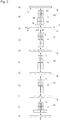
- FIG. 1 is an embodiment of the manufacturing process for the at least one sheet metal profile shown schematically in a perspective view.
- a sheet metal strand 6, which comprises a flat surface 3 is processed in five process steps by means of deforming devices in the form of roll forming sets 10, 11, 12, 13 and 14.
- a person skilled in the art also speaks of "stitches" in connection with processing by profiling rollers.
- the sheet metal strand 6 is therefore processed in five successive stitches.
- the sheet-metal strand 6 is moved along its longitudinal direction 4 through the deforming devices 10, 11, 12, 13 and 14. The direction of movement is indicated by an arrow.
- the sheet metal strand 6 comprises in the illustrated example, only a flat surface 3, but it may also be the case according to preferred embodiments that an already partially formed sheet metal strip is fed to the deformation devices and / or the sheet metal strand further formed after processing, preferably bent , becomes.
- At least one first and at least one further process step are required.
- five method steps are shown.
- preferably ten to fifteen further method steps take place.
- this preferred embodiment has not been shown here for the sake of clarity.
- Each of these deformation devices 10, 11, 12, 13 and 14 comprises a profiling roller set with a first profiling roller 15 and two further profiling rollers 16 and 17.
- Each of these profiling rollers 15, 16 and 17 has substantially the shape of a cylinder with a lateral surface 15, 26 and 27 and two end faces, which are provided in the case of two further profiling rollers with the reference numerals 28 and 29.
- the relative spatial arrangement of the profiling rollers 15, 16 and 17 to each other is in the description of the Fig. 3a) to 3e ).
- Fig. 2a) to 2k) serves the illustration of the in the Fig. 1 illustrated method steps, the figures in alphabetical order denoted by the Roman numerals I to XI cross-sectional planes of the Fig. 1 to be added, it being added that in the case of Fig. 2b), 2d), 2f), 2h) and 2j ) the sheet metal profile 6 has been omitted for clarity.
- Fig. 3a) to 3e explained.
- Starting point of the method is the sheet metal strand 6 with at least one flat surface 3 (s. Fig. 2a )).
- a laterally, in this case perpendicular, projecting web 5 is squeezed out of the flat surface 3 of this sheet metal strand 6. How this works in detail is based on the Fig. 3a ) explained. Characterized in that the sheet metal strand 6 is moved relative to the deforming device 10, this web 5 extends in the longitudinal direction 4 of the sheet metal strand 6 (s. Fig. 1 ).
- the web 5 After the first method step, the web 5 has a specific shape, which depends on the configuration of the deformation tools used in the first method step.
- the web 5 - viewed in cross section - a substantially rectangular shape with a certain width 7 and a certain height 8.
- this web 5 can now be changed in further process steps, namely by the web 5 is squeezed together, ie reduced in its width 7 and increased in height 8 (s. 2e), 2g), 2i) and 2k) ).
- the web 5 can be dimensioned in principle depending on the number of coming to use further process steps in principle.
- a backflow of the sheet material in the flat surface 3 of the sheet metal strand 6 is inhibited by limiting material cuts 9 during the process steps.
- the process is carried out at room temperature, that is typically at a temperature between 15 ° C and 25 ° C.
- the sheet metal strand by an active drive of the profiling rollers 15, 16 and 17, e.g. at a speed of 1 m / min to 300 m / min, is moved. Both a continuous and a start-stop operation is conceivable.
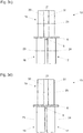
- Fig. 3a) to 3e which in detail cross sections along the cross-sectional planes II, IV, VI, VIII and X from the Fig. 1 demonstrate.
- the basic structure of the deformation devices 10, 11, 12, 13 and 14 used in the five illustrated stitches is, as already stated, the same in each case.
- Each of these deformation devices 10, 11, 12, 13 and 14 comprises a profiling roller set with a first profiling roller 15 and two further profiling rollers 16 and 17, wherein between the first profiling roller 15 and the two further profiling rollers 16 and 17, a first gap 18 with a gap width, which essentially corresponds to the material thickness of the sheet metal strand 6 is arranged. Between the two further profiling rollers 16 and 17, a second gap 19 is arranged.
- the first profiling roller 15 has on its lateral surface 20 (s. Fig. 1 ) has an annular bulge 21 with a width 22. This annular bulge 21 of the first profiling roller 15 and the second, arranged between the two further profiling rollers 16 and 17 gap 19 are opposite to each other.
- the axes of rotation 23 and 24 of the two further profiling rollers 16 and 17 are aligned parallel to the axis of rotation 25 of the first profiling roller 15.
- the first gap 18 between the lateral surfaces 26 and 27 of the two further profiling rollers 16 and 17 and the lateral surface 20 of the first profiling roller 15 and the second gap 19 between the end faces 28 and 29 of the two further profiling rollers 16 and 17 see also Fig. 1 ).
- Profilierwalzensatz 14 shown in comparison are the axes of rotation 23 and 24 of the two further profiling rollers 16 and 17 perpendicular to the axis of rotation 25 of the first profiling roller 15 and at the same time aligned parallel to each other.
- the first gap 18 is thus located between the end faces 28 and 29 of the two further profiling rollers 16 and 17 and the lateral surface 20 of the first profiling roller 15 (see also Fig. 1 ).
- the second gap 19 is arranged between the lateral surfaces 26 and 27 of the two further profiling rollers 16 and 17.
- the last-described arrangement of the profiling rollers 15, 16 and 17 relative to one another is preferably used at least in the last method step, particularly preferably from the third method step, since by this arrangement of the profiling rollers 16 and 17 relative to the flat surface 3 of the sheet metal strand 6 a larger processing surface takes effect. In this way, the surfaces 5 of the sheet-metal strip 6 adjacent to the crimped-profiled web 5 can be smoothed in the or in the final method steps.
- Fig. 7a) and 7b instead of the two further profiling rollers 16 and 17, only one profiling roller 50 having a groove-shaped recess 52 whose width corresponds to the gap width of the second gap 19 arranged between the two further profiling rollers 16 and 17 is used (cf. Fig. 3a )).
- This situation is in the Fig. 7a) and 7b ), wherein the Fig. 7a ) is a cross-sectional view and the Fig. 7b ) shows a perspective view.
- the sheet metal strand 6 is passed through further profiling rolls sets 11, 12, 13 and 14 in further process steps, wherein these profiling rolls sets 11, 12, 13 and 14 each have a relation to FIG have previous profiling roller 10, 11, 12 and 13 gradually reduced gap width of the second gap 19.
- these profiling rolls sets 11, 12, 13 and 14 each have a relation to FIG have previous profiling roller 10, 11, 12 and 13 gradually reduced gap width of the second gap 19.
- the web 5 is forcibly squeezed together, that is, the width 7 of the web is reduced while the height 8 is increased. This is exemplified by the sequence of Fig. 3a) to 3e ) recognizable.
- sheet metal profiles for drawer pull-out guides can be produced using the manufacturing process, eg made of steel.
- the sheet metal strip is formed before, and / or after the crimping of the at least one web in the course of the first and the at least one further process step by means of further profiling rollers, preferably bent.
- a last step then separated from a continuous or in a start-stop operation produced material strand sheet metal profiles of a predetermined length.
- FIG. 4 is exemplified in cross-section a conceivable drawer pull-out 2, which comprises two manufactured by means of an embodiment of the manufacturing process sheet metal profiles 32 and 33 shown.
- a drawer pull-out guide typically has a cabinet rail 32 to be fastened to a furniture carcass, a drawer rail 33 to be fastened to the drawer and a middle rail 34 movably mounted between the carcass rail 32 and the drawer rail 33.
- Between the rails 32, 33 and 34 are typically arranged carriage with load-transmitting rolling elements 46, 47 and 48, 49, which allow relative movement of the rails 32, 33 and 34 to each other.
- both the carcass rail 32 and the drawer rail 33 comprise a web 35 or 36, wherein these webs 35 and 36 can be produced by means of the crushing described above.
- the rolling element 46 which is arranged between the middle rail 34 and the carcass rail 32, runs on the web 35.
- the web 36 serves to space the two rolling elements 48 and 49 from one another and at the same time to provide a bearing for the rolling element 48.
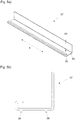
- FIG. 5a) and 5b another example of a cabinet rail 37 is shown, wherein the Fig. 5a ) a perspective and the Fig. 5b ) shows a cross-sectional view of this carcass rail 37.
- two webs 38 and 39 are arranged, which can be formed by the described Quetschprofilieren. They represent reinforcing ribs in this case, which serve to reinforce the carcass rail 37.
- a center rail 40 of a drawer pull-out guide is exemplified, wherein the Fig. 6a ) an overall perspective view and the Fig. 6b ) shows a section of this overall view.
- the illustrated center rail 40 consists - viewed in cross-section - essentially of a U-profile, wherein on the two lateral, opposing legs of this U-profile two crimp-shaped webs 41 and 42 are arranged, of the flat surfaces 44th and 45 stick out.
- the rolling elements of between the middle rail 40 and a (not shown) drawer runner arranged (also not shown) run off, said carriage the webs 41 and 42 in the use position of the pull-out with its rolling elements to protect against lifting engages under the middle rail 40.
- the center rail 40 is secured against lifting from the carcass rail, a, especially occurring in a fully extended drawer, tilting the drawer can be prevented.
- rolling elements is to be understood very broadly and, for example, can be realized as a roll, cylindrical roller or ball.
- the rolling element can comprise both an axle bearing and also axleless, e.g. in a cage, be guided.
Landscapes
- Engineering & Computer Science (AREA)
- Mechanical Engineering (AREA)
- Physics & Mathematics (AREA)
- Geometry (AREA)
- Bending Of Plates, Rods, And Pipes (AREA)
- Metal Rolling (AREA)
- Drawers Of Furniture (AREA)
Description
- Die Erfindung betrifft eine Schubladen-Ausziehführung, umfassend eine an einem Möbelkorpus zu befestigende Korpusschiene, eine an der Schublade zu befestigende Ladenschiene und eine zwischen der Korpusschiene und der Ladenschiene begwebar gelagerte Mittelschiene (siehe z.B.
EP-A2-0 613 640 ). - Ein Herstellungsverfahren für Blechprofile - allerdings nicht explizit auf die Herstellung eines Blechprofils für eine Schubladen-Ausziehführung ausgerichtet - ist unter dem Namen "Spaltprofilieren" bekannt, welches Gegenstand der
DE 100 39 768 A1 ist, wobei bei diesem Verfahren mittels einer am Rand eines Bleches angreifenden Umformwalze mindestens ein von der Blechebene wegweisender Flansch mit geringerer Dicke als der Ausgangswerkstückdicke aus dem Blechrand geformt wird. Der auf diese Weise erzeugte Flansch kann dann in weiterer Folge relativ zum Ausgangsblech weiter verformt werden (vergleiche dieDE 103 05 542 A1 ). - Nachteilig bei dem aus dem Stand der Technik bekannten Verfahren ist, dass der Flansch zum einen nur aus dem Blechrand geformt werden kann und dass der Flansch zum anderen eine im Vergleich zu dem Ausgangsblech geringere Dicke aufweist. Dadurch ist das Verfahren für eine Reihe von Anwendungsbereichen, z.B. Schubladen-Ausziehführungen, ungeeignet.
- Die
JP S60 102202 A JP 2012 161842 A JP 2010 149181 A US 2 361 729 A und dieJP 2009 022992 A - Die Aufgabe der vorliegenden Erfindung besteht darin, eine gegenüber dem Stand der Technik verbesserte Schubladen-Ausziehführung anzugeben.
- Diese Aufgabe wird gelöst durch die Merkmale des unabhängigen Anspruchs 1.
- Zur Lösung dieser Aufgabe ist es also erfindungsgemäß vorgesehen, dass die Korpusschiene, die Ladenschiene und/oder die Mittelschiene einem Blechprofil, insbesondere aus Stahl, für eine Schubladen-Ausziehführung mit zumindest einem von einer ebenen Fläche des Blechprofils seitlich, insbesondere senkrecht, abstehenden und sich in Längsrichtung des Blechprofils erstreckenden Steg, hergestellt nach dem folgenden Verfahren entspricht: Verfahren zur Herstellung eines, insbesondere aus Stahl bestehenden, Blechprofils für eine Schubladen-Ausziehführung mit zumindest einem von einer ebenen Fläche des Blechprofils seitlich, insbesondere senkrecht, abstehenden und sich in Längsrichtung des Blechprofils erstreckenden Steg, wobei
- in einem ersten Verfahrensschritt aus wenigstens einer ebenen Fläche eines Blechstrangs zumindest ein seitlich, insbesondere senkrecht, abstehender und sich in Längsrichtung des Blechstrangs erstreckender Steg herausgequetscht wird, und
- der zumindest eine Steg in wenigstens einem weiteren Verfahrensschritt, vorzugsweise in 10 bis 15 weiteren Verfahrensschritten, zusammengequetscht wird, d.h. in seiner Breite reduziert und in seiner Höhe vergrößert wird.
- Durch das angesprochene Verfahren ist es im Vergleich zum Stand der Technik möglich, den zumindest einen Steg in irgendeinem Bereich einer ebenen Fläche eines Blechstrangs, also nicht nur im Randbereich, zu erzeugen und gleichzeitig - je nachdem wie weit man den zumindest einen Steg in den weiteren Verfahrensschritten zusammenquetscht - beliebig zu dimensionieren, das heißt die Parameter Breite und Höhe des Stegs an seinen spezifischen Anwendungszweck anzupassen.
- Vorteilhafte Ausführungsformen der Erfindung werden zusammen mit weiteren Einzelheiten und Vorteilen der Erfindung im Rahmen der folgenden Beschreibung der Figuren näher erläutert. Dabei zeigt
- Fig. 1
- eine schematische Übersichtsdarstellung eines Ausführungsbeispiels des Herstellungsverfahrens für das zumindest eine Blechprofil in einer perspektivischen Ansicht,
- Fig. 2a) bis 2k)
- eine Abfolge schematisch dargestellter Querschnittsansichten der in der
Fig. 1 angedeuteten Querschnittsebenen I bis XI, wobei bei den Querschnittsdarstellungen derFig. 2b), 2d), 2f), 2h) und 2j ) der Blechstrang weggelassen wurde, - Fig. 3a) bis 3e)
- vergrößerte schematische Querschnittsansichten der in der
Fig. 1 angedeuteten Querschnittebenen II, IV, VI, VIII und X, - Fig. 4
- den schematisch dargestellten Querschnitt eines möglichen Ausführungsbeispiels einer Schubladen-Ausziehführung,
- Fig. 5a) und 5b)
- ein Ausführungsbeispiel eines Blechprofils, welches bei einer Schubladen-Ausziehführung als Korpusschiene verwendet werden kann, wobei die
Fig. 5a ) eine perspektivische und dieFig. 5b ) eine Querschnittsansicht zeigt, - Fig. 6a) und 6b)
- ein weiteres Ausführungsbeispiel des Blechprofils, welches bei einer Schubladen-Ausziehführung als Mittelschiene verwendet werden kann, wobei die
Fig. 6a ) eine perspektivische Gesamtansicht und dieFig. 6b ) einen vergrößerten Ausschnitt daraus zeigt, und - Fig. 7a) und 7b)
- eine beim Verfahren zum Einsatz kommende Profilierwalze.
- In der
Fig. 1 ist in einer perspektivischen Ansicht ein Ausführungsbeispiel des Herstellungsverfahrens für das zumindest eine Blechprofil schematisch dargestellt. Ein Blechstrang 6, der eine ebene Fläche 3 umfasst, wird in fünf Verfahrensschritten mittels Verformvorrichtungen in Form von Profilierwalzensätzen 10, 11, 12, 13 und 14 bearbeitet. Ein Fachmann spricht in Zusammenhang mit der Bearbeitung durch Profilierwalzen auch von "Stichen". In dem dargestellten Fall wird der Blechstrang 6 demzufolge in fünf aufeinanderfolgenden Stichen bearbeitet. Dabei wird der Blechstrang 6 entlang seiner Längsrichtung 4 durch die Verformvorrichtungen 10, 11, 12, 13 und 14 hindurchbewegt. Die Bewegungsrichtung ist mittels eines Pfeils gekennzeichnet. - Der Blechstrang 6 umfasst in dem dargestellten Beispiel zwar nur eine ebene Fläche 3, jedoch kann es gemäß bevorzugten Ausführungsbeispielen auch der Fall sein, dass ein bereits teilumgeformter Blechstrang den Verformvorrichtungen zugeführt wird und/oder der Blechstrang im Anschluss an die Bearbeitung weiter umgeformt, vorzugsweise verbogen, wird.
- Zur Durchführung des Verfahrens werden mindestens ein erster und wenigstens ein weiterer Verfahrensschritt benötigt. In dem dargestellten Beispiel sind, wie bereits ausgeführt, fünf Verfahrensschritte dargestellt. Bevorzugt finden neben einem ersten Verfahrensschritt zehn bis fünfzehn weitere Verfahrensschritte statt. Diese bevorzugte Ausführungsform wurde hier der Übersichtlichkeit halber jedoch nicht dargestellt.
- Zur Illustration der einzelnen Verfahrensschritte dienen die
Fig. 2a) bis 2k) sowie3a) bis 3e) , wobei diese Figuren jeweils einen bestimmten mittels strichpunktierter Linien angedeuteten Querschnitt aus dem inFig. 1 dargestellten Aufbau zeigen. - Vorab sei noch kurz auf den Grundaufbau der bevorzugt zum Einsatz kommenden Verformvorrichtungen 10, 11, 12, 13 und 14 eingegangen: Jede dieser Verformvorrichtungen 10, 11, 12, 13 und 14 umfasst einen Profilierwalzensatz mit einer ersten Profilierwalze 15 und zwei weiteren Profilierwalzen 16 und 17. Jede dieser Profilierwalzen 15, 16 und 17 hat im Wesentlichen die Form eines Zylinders mit einer Mantelfläche 15, 26 bzw. 27 und zwei Stirnflächen, die im Falle der zwei weiteren Profilierwalzen mit den Bezugszeichen 28 und 29 versehen sind. Auf weitere Einzelheiten, wie z.B. die relative räumliche Anordnung der Profilierwalzen 15, 16 und 17 zueinander, wird im Zuge der Beschreibung der
Fig. 3a) bis 3e ) näher eingegangen. - Die Abfolge der
Fig. 2a) bis 2k) dient der Illustration der in derFig. 1 dargestellten Verfahrensschritte, wobei die Figuren in alphabetischer Reihenfolge den mit den römischen Ziffern I bis XI bezeichneten Querschnittsebenen aus derFig. 1 entsprechen, wobei hinzugefügt sei, dass bei denFig. 2b), 2d), 2f), 2h) und 2j ) das Blechprofil 6 der Übersichtlichkeit halber weggelassen wurde. Diese fünf Querschnittsdarstellungen werden näher anhand derFig. 3a) bis 3e ) erläutert. - Ausgangspunkt des Verfahrens ist der Blechstrang 6 mit wenigstens einer ebenen Fläche 3 (s.
Fig. 2a )). In einem ersten Verfahrensschritt wird aus der ebenen Fläche 3 dieses Blechstrangs 6 ein seitlich, in diesem Fall senkrecht, abstehender Steg 5 herausgequetscht. Wie dies im Einzelnen abläuft wird anhand derFig. 3a ) erläutert. Dadurch, dass der Blechstrang 6 relativ zu der Verformvorrichtung 10 bewegt wird, erstreckt sich dieser Steg 5 in Längsrichtung 4 des Blechstrangs 6 (s.Fig. 1 ). - Nach dem ersten Verfahrensschritt weist der Steg 5 eine bestimmte Form auf, die von der Ausgestaltung der beim ersten Verfahrensschritt zum Einsatz kommenden Verformwerkzeuge abhängt. In dem dargestellten Ausführungsbeispiel (s.
Fig. 2c )) weist der Steg 5 - im Querschnitt betrachtet - eine im Wesentlichen rechteckige Form mit einer bestimmten Breite 7 und einer bestimmten Höhe 8 auf. - Die Dimensionen dieses Stegs 5 können nun in weiteren Verfahrensschritten verändert werden, und zwar indem der Steg 5 zusammengequetscht wird, d.h. in seiner Breite 7 reduziert und in seiner Höhe 8 vergrößert wird (s.
Fig. 2e), 2g), 2i) und 2k) ). Je nachdem, welchen Zweck der Steg 5 erfüllen soll, kann er in Abhängigkeit von der Anzahl der zum Einsatz kommenden weiteren Verfahrensschritte im Prinzip beliebig dimensioniert werden. - Vorteilhafter Weise wird während der Verfahrensschritte ein Zurückfließen des Blechmaterials in die ebene Fläche 3 des Blechstrangs 6 durch begrenzende Materialeinschnitte 9 gehemmt.
- Allgemein sei noch darauf hingewiesen, dass das Verfahren bei Raumtemperatur durchgeführt wird, also typischerweise bei einer Temperatur zwischen 15°C und 25°C. Weiterhin ist es bevorzugt vorgesehen, dass der Blechstrang durch einen aktiven Antrieb der Profilierwalzen 15, 16 und 17, z.B. mit einer Geschwindigkeit von 1 m/min bis 300 m/min, fortbewegt wird. Dabei ist sowohl ein kontinuierlicher als auch ein Start-Stopp-Betrieb denkbar.
- Wenden wir uns nun den
Fig. 3a) bis 3e ) zu, welche im Detail Querschnitte entlang der Querschnittsebenen II, IV, VI, VIII und X aus derFig. 1 zeigen. Der Grundaufbau der bei den fünf dargestellten Stichen zum Einsatz kommenden Verformvorrichtungen 10, 11, 12, 13 und 14 ist, wie bereits gesagt, jeweils der gleiche. Jede dieser Verformvorrichtungen 10, 11, 12, 13 und 14 umfasst einen Profilierwalzensatz mit einer ersten Profilierwalze 15 und zwei weiteren Profilierwalzen 16 und 17, wobei zwischen der ersten Profilierwalze 15 und den zwei weiteren Profilierwalzen 16 und 17 ein erster Spalt 18 mit einer Spaltbreite, die im Wesentlichen der Materialstärke des Blechstrangs 6 entspricht, angeordnet ist. Zwischen den zwei weiteren Profilierwalzen 16 und 17 ist ein zweiter Spalt 19 angeordnet. - Die erste Profilierwalze 15 weist an ihrer Mantelfläche 20 (s.
Fig. 1 ) eine ringförmige Auswölbung 21 mit einer Breite 22 auf. Diese ringförmige Auswölbung 21 der ersten Profilierwalze 15 und der zweite, zwischen den zwei weiteren Profilierwalzen 16 und 17 angeordnete Spalt 19 liegen einander gegenüber. - Bei den ersten vier dargestellten Profilierwalzensätzen 10, 11, 12 und 13 (s.
Fig. 3a) bis 3d )) sind die Drehachsen 23 und 24 der zwei weiteren Profilierwalzen 16 und 17 parallel zur Drehachse 25 der ersten Profilierwalze 15 ausgerichtet. Somit ist der erste Spalt 18 zwischen den Mantelflächen 26 und 27 der zwei weiteren Profilierwalzen 16 und 17 und der Mantelfläche 20 der ersten Profilierwalze 15 angeordnet und der zweite Spalt 19 zwischen den Stirnflächen 28 und 29 der zwei weiteren Profilierwalzen 16 und 17 (s. auchFig. 1 ). - Bei dem in
Fig. 3e ) dargestellten Profilierwalzensatz 14 sind im Vergleich dazu die Drehachsen 23 und 24 der zwei weiteren Profilierwalzen 16 und 17 senkrecht zur Drehachse 25 der ersten Profilierwalze 15 und gleichzeitig parallel zueinander ausgerichtet. Der erste Spalt 18 befindet sich somit zwischen den Stirnflächen 28 und 29 der zwei weiteren Profilierwalzen 16 und 17 und der Mantelfläche 20 der ersten Profilierwalze 15 (s. auchFig. 1 ). Der zweite Spalt 19 ist zwischen den Mantelflächen 26 und 27 der zwei weiteren Profilierwalzen 16 und 17 angeordnet. - Die zuletzt beschriebene Anordnung der Profilierwalzen 15, 16 und 17 zueinander kommt bevorzugt zumindest bei dem letzten Verfahrensschritt, besonders bevorzugt ab dem dritten Verfahrensschritt, zum Einsatz, da durch diese Anordnung der Profilierwalzen 16 und 17 relativ zur ebenen Fläche 3 des Blechstrangs 6 eine größere Bearbeitungsfläche wirksam wird. Auf diese Weise können die zum quetschprofilierten Steg 5 benachbarte Flächen des Blechstrangs 6 in dem bzw. in den abschließenden Verfahrensschritten geglättet werden.
- Gemäß einem bevorzugten Ausführungsbeispiel wird anstelle der zwei weiteren Profilierwalzen 16 und 17 nur eine Profilierwalze 50 mit einer rillenförmigen Ausnehmung 52, deren Breite der Spaltbreite des zweiten, zwischen den zwei weiteren Profilierwalzen 16 und 17 angeordneten, Spalts 19 entspricht, verwendet (vgl. z.B.
Fig. 3a )). Diese Situation ist in denFig. 7a) und 7b ) dargestellt, wobei dieFig. 7a ) eine Querschnittsansicht und dieFig. 7b ) eine perspektivische Ansicht zeigt. - Wie wird nun im Einzelnen der Steg 5 im Zuge des ersten Verfahrensschrittes aus dem Blechstrang 6 herausgequetscht? Hierzu wird der Blechstrang 6 mit der ebenen Fläche 3 durch den ersten Spalt 18 des ersten Profilierwalzensatzes 10 hindurchgeführt (s.
Fig. 3a )). Dabei wird von der ringförmigen Auswölbung 21 der ersten Profilierwalze 15 ein Steg 5 aus der ebenen Fläche 3 des Blechstrangs 6 heraus- und in den zweiten, zwischen den zwei weiteren Profilierwalzen 16 und 17 angeordneten, Spalt 19 hineingequetscht, wobei dieser Steg 5 in seinen Abmessungen, das heißt in seiner Breite 7 und in seiner Höhe 8, im Wesentlichen den Abmessungen der ringförmigen Auswölbung 21 der ersten Profilierwalze 15 entspricht. - Das bereits angesprochene Hemmen des Zurückfließens des Blechmaterials in die ebene Fläche 3 des Blechstrangs 6 wird dadurch realisiert, dass die ringförmige Auswölbung 21 der ersten Profilierwalze 15 durch Vorsprünge 30 und 31, die z.B. torusförmig ausgebildet sein können, begrenzt wird. Mittels dieser Vorsprünge 30 und 31 werden - im Querschnitt betrachtet - rechts und links von dem herausgequetschten Steg 5 Materialeinschnitte 9 (s.
Fig. 2c )) erzeugt. Dadurch dass das Zurückfließens des Blechmaterials während der Verfahrensschritte gehemmt, im Idealfall vollständig unterbunden, wird, bleibt das Materialvolumen des Stegs 5 nahezu konstant. - Zur weiteren Änderung der Abmessungen 7 und 8 des im Zuge des ersten Verfahrensschrittes gebildeten Stegs 5 wird der Blechstrang 6 in weiteren Verfahrensschritten durch weitere Profilierwalzensätze 11, 12, 13 und 14 hindurchgeführt, wobei diese Profilierwalzensätze 11, 12, 13 und 14 jeweils eine gegenüber dem vorhergehenden Profilierwalzensatz 10, 11, 12 bzw. 13 schrittweise reduzierte Spaltbreite des zweiten Spaltes 19 aufweisen. Dadurch wird der Steg 5 zwangsweise zusammengequetscht, das heißt, die Breite 7 des Stegs wird reduziert und gleichzeitig die Höhe 8 vergrößert. Dies ist exemplarisch anhand der Abfolge der
Fig. 3a) bis 3e ) erkennbar. - Wie schon in der Beschreibungseinleitung ausgeführt, können mithilfe des Herstellungsverfahrens z.B. aus Stahl bestehende Blechprofile für Schubladen-Ausziehführungen hergestellt werden. Hierzu wird der Blechstrang vor der und/oder im Anschluss an die Quetschbildung des zumindest einen Stegs im Zuge des ersten und des wenigstens einen weiteren Verfahrensschrittes mittels weiterer Profilierwalzen umgeformt, vorzugsweise verbogen. In einem letzten Verfahrensschritt werden dann von einem kontinuierlichen oder in einem Start-Stopp-Betrieb hergestellten Materialstrang Blechprofile einer vorbestimmten Länge abgetrennt.
- In der
Fig. 4 ist exemplarisch im Querschnitt eine denkbare Schubladen-Ausziehführung 2, die zwei mittels eines Ausführungsbeispiels des Herstellungsverfahrens hergestellte Blechprofile 32 und 33 umfasst, dargestellt. Eine solche Schubladen-Ausziehführung weist typischerweise eine an einem Möbelkorpus zu befestigende Korpusschiene 32, eine an der Schublade zu befestigende Ladenschiene 33 und eine zwischen der Korpusschiene 32 und der Ladenschiene 33 bewegbar gelagerte Mittelschiene 34 auf. Zwischen den Schienen 32, 33 und 34 sind typischerweise Laufwagen mit lastübertragenden Wälzkörpern 46, 47 und 48, 49 angeordnet, die eine relative Bewegung der Schienen 32, 33 und 34 zueinander ermöglichen. - In dem dargestellten Beispiel umfassen sowohl die Korpusschiene 32 als auch die Ladenschiene 33 einen Steg 35 bzw. 36, wobei diese Stege 35 bzw. 36 mittels der weiter oben beschriebenen Quetschbildung hergestellt werden können. Im Falle der Korpusschiene 32 läuft an dem Steg 35 der Wälzkörper 46, der zwischen der Mittelschiene 34 und der Korpusschiene 32 angeordnet ist, ab. Im Falle der Ladenschiene 33 dient der Steg 36 dazu, die zwei Wälzkörper 48 und 49 voneinander zu beabstanden und gleichzeitig ein Lager für den Wälzköper 48 bereitzustellen.
- In den
Fig. 5a) und 5b ) ist ein weiteres Beispiel einer Korpusschiene 37 dargestellt, wobei dieFig. 5a ) eine perspektivische und dieFig. 5b ) eine Querschnittsansicht dieser Korpusschiene 37 zeigt. An der ebenen Fläche 43 der Korpusschiene 37 sind zwei Stege 38 und 39 angeordnet, welche durch das beschriebene Quetschprofilieren gebildet werden können. Sie stellen in diesem Fall Verstärkungsrippen dar, welche der Verstärkung der Korpusschiene 37 dienen. - In den
Fig. 6a) und 6b ) ist beispielhaft eine Mittelschiene 40 einer Schubladen-Ausziehführung dargestellt, wobei dieFig. 6a ) eine perspektivische Gesamtansicht und dieFig. 6b ) einen Ausschnitt dieser Gesamtansicht zeigt. Die dargestellte Mittelschiene 40 besteht - im Querschnitt betrachtet - im Wesentlichen aus einem U-Profil, wobei an den beiden seitlichen, einander gegenüberliegenden Schenkeln dieses U-Profils zwei quetschprofilierte Stege 41 bzw. 42 angeordnet sind, die von den ebenen Flächen 44 und 45 abstehen. An diesen Stegen 41 und 42 können die Wälzkörper eines zwischen der Mittelschiene 40 und einer (nicht dargestellten) Ladenschiene angeordneten Laufwagens (ebenfalls nicht dargestellt) ablaufen, wobei dieser Laufwagen die Stege 41 und 42 in Gebrauchslage der Ausziehführung mit seinen Wälzkörpern zur Sicherung gegen ein Abheben von der Mittelschiene 40 untergreift. Auf diese Weise kann, wenn gleichzeitig auch die Mittelschiene 40 gegen ein Abheben von der Korpusschiene gesichert ist, ein, insbesondere bei einer vollständig ausgezogenen Schublade auftretendes, Kippspiel der Schublade verhindert werden. - Abschließend sei festgehalten, dass der Begriff "Wälzkörper" sehr breit aufzufassen ist und z.B. als Rolle, zylindrische Walze oder Kugel realisiert sein kann. Dabei kann der Wälzkörper sowohl ein Achslager umfassen als auch achslos, z.B. in einem Käfig, geführt sein.
Claims (2)
- Schubladen-Ausziehführung (2), umfassend- eine an einem Möbelkorpus zu befestigende Korpusschiene (32, 37),- eine an der Schublade zu befestigende Ladenschiene (33) und- eine zwischen der Korpusschiene (32, 37) und der Ladenschiene (33) bewegbar gelagerte Mittelschiene (34, 40),dadurch gekennzeichnet, dass die Korpusschiene (32, 37), die Ladenschiene (33) und/oder die Mittelschiene (34, 40) einem Blechprofil (1, 32, 33, 37, 40), insbesondere aus Stahl, für eine Schubladen-Ausziehführung (2) mit zumindest einem von einer ebenen Fläche (3, 43, 44, 45) des Blechprofils (1, 32, 33, 37, 40) seitlich, insbesondere senkrecht, abstehenden und sich in Längsrichtung (4) des Blechprofils (1, 32, 33, 37, 40) erstreckenden Steg (5, 35, 36, 38, 39, 41, 42), hergestellt nach dem folgenden Verfahren entspricht: Verfahren zur Herstellung eines, insbesondere aus Stahl bestehenden, Blechprofils (1, 32, 33, 37, 40) für eine Schubladen-Ausziehführung (2) mit zumindest einem von einer ebenen Fläche (3, 43, 44, 45) des Blechprofils (1, 32, 33, 37, 40) seitlich, insbesondere senkrecht, abstehenden und sich in Längsrichtung (4) des Blechprofils (1, 32, 33, 37, 40) erstreckenden Steg (5, 35, 36, 38, 39, 41, 42), wobei in einem ersten Verfahrensschritt aus wenigstens einer ebenen Fläche (3, 43, 44, 45) eines Blechstrangs (6) zumindest ein seitlich, insbesondere senkrecht, abstehender und sich in Längsrichtung (4) des Blechstrangs (6) erstreckender Steg (5, 35, 36, 38, 39, 41, 42) herausgequetscht wird, und der zumindest eine Steg (5, 35, 36, 38, 39, 41, 42) in wenigstens einem weiteren Verfahrensschritt, vorzugsweise in 10 bis 15 weiteren Verfahrensschritten, zusammengequetscht wird, d.h. in seiner Breite (7) reduziert und in seiner Höhe (8) vergrößert wird.
- Schubladen-Ausziehführung (2) nach Anspruch 1, dadurch gekennzeichnet, dass an einer der Schienen (32, 33, 34, 37, 40) wenigstens ein Wälzkörper (46, 47, 48, 49) gelagert ist, der an dem zumindest einen Steg (5, 35, 36, 38, 39, 41, 42) einer anderen Schiene (32, 33, 34, 37, 40) abläuft, und/oder dass der zumindest eine Steg (5, 35, 36, 38, 39, 41, 42) einer der Schienen (32, 33, 34, 37, 40) eine Verstärkungsrippe darstellt.
Applications Claiming Priority (2)
| Application Number | Priority Date | Filing Date | Title |
|---|---|---|---|
| ATA1213/2012A AT512899B1 (de) | 2012-11-15 | 2012-11-15 | Verfahren zur Herstellung eines Blechprofils für eine Schubladen-Ausziehführung |
| PCT/AT2013/000181 WO2014075115A1 (de) | 2012-11-15 | 2013-11-06 | Verfahren zur herstellung eines blechprofils für eine schubladen-ausziehführung sowie dadurch hergestelltes blechprofil und dadurch hergestellte schubladen-ausziehführung |
Publications (2)
| Publication Number | Publication Date |
|---|---|
| EP2919620A1 EP2919620A1 (de) | 2015-09-23 |
| EP2919620B1 true EP2919620B1 (de) | 2019-02-06 |
Family
ID=49758940
Family Applications (1)
| Application Number | Title | Priority Date | Filing Date |
|---|---|---|---|
| EP13802849.3A Active EP2919620B1 (de) | 2012-11-15 | 2013-11-06 | Verfahren zur herstellung eines blechprofils für eine schubladen-ausziehführung sowie dadurch hergestelltes blechprofil und dadurch hergestellte schubladen-ausziehführung |
Country Status (9)
| Country | Link |
|---|---|
| US (1) | US9993857B2 (de) |
| EP (1) | EP2919620B1 (de) |
| JP (1) | JP6212126B2 (de) |
| KR (2) | KR101808498B1 (de) |
| CN (1) | CN104837381B (de) |
| AT (1) | AT512899B1 (de) |
| ES (1) | ES2724875T3 (de) |
| MY (1) | MY186231A (de) |
| WO (1) | WO2014075115A1 (de) |
Families Citing this family (5)
| Publication number | Priority date | Publication date | Assignee | Title |
|---|---|---|---|---|
| US9682411B1 (en) * | 2014-03-06 | 2017-06-20 | Overhead Door Corporation | Variable pressure door facade forming |
| DE102016200520B4 (de) * | 2015-03-19 | 2019-10-31 | Ford Global Technologies, Llc | Verfahren zur Herstellung eines Strukturbauteils sowie Walzeinrichtung |
| US20180169722A1 (en) * | 2016-12-15 | 2018-06-21 | GM Global Technology Operations LLC | Systems, methods and devices for 3d rolling of multi-gauge parts |
| AT525324B1 (de) * | 2021-07-23 | 2024-09-15 | Blum Gmbh Julius | Schubladenausziehführung zur bewegbaren Lagerung einer Schublade an einem Möbelkorpus |
| CN114309060A (zh) * | 2022-01-04 | 2022-04-12 | 刘淑容 | 碾压成型设备和物料生产线 |
Family Cites Families (24)
| Publication number | Priority date | Publication date | Assignee | Title |
|---|---|---|---|---|
| US2361729A (en) * | 1939-02-18 | 1944-10-31 | Nedden Gerhard Zur | Method of rolling strip irons |
| JPS5449966A (en) * | 1977-09-28 | 1979-04-19 | Minoru Yamagata | Method of making ttor crossssectioned metal bar |
| DE2813636C3 (de) * | 1978-03-30 | 1980-10-30 | Theodor Wuppermann Gmbh, 5090 Leverkusen | Verfahren und Einrichtung zur Herstellung von Profilen aus Metall, vornehmlich von Stahlprofilen |
| JPS6011563B2 (ja) * | 1980-06-11 | 1985-03-27 | 日本鋼管株式会社 | T形鋼の圧延方法 |
| JPS58135704A (ja) * | 1982-02-05 | 1983-08-12 | Kawasaki Steel Corp | T形鋼または山形鋼の製造方法および製造装置 |
| JPS60102202A (ja) * | 1983-11-10 | 1985-06-06 | Nippon Kokan Kk <Nkk> | T形鋼の圧延方法 |
| JPS60102205A (ja) * | 1983-11-10 | 1985-06-06 | Nippon Kokan Kk <Nkk> | 3軸圧延機によるt形鋼の圧延方法 |
| AT387897B (de) * | 1984-12-20 | 1989-03-28 | Blum Gmbh Julius | Unterflur-fuehrungsschienengarnitur |
| JPS61216831A (ja) * | 1985-03-20 | 1986-09-26 | Hitachi Ltd | 長尺形材の製造方法 |
| JPH0466201A (ja) | 1990-06-29 | 1992-03-02 | Aichi Steel Works Ltd | 溝形材の製造方法 |
| AT400218B (de) | 1993-03-04 | 1995-11-27 | Blum Gmbh Julius | Ausziehführung für schubladen |
| US5536083A (en) * | 1993-03-04 | 1996-07-16 | Julius Blum Gesellschaft M.B.H. | Pull-out guide assembly for drawers |
| EP0613640A3 (de) * | 1993-03-04 | 1998-01-21 | Julius Blum Gesellschaft m.b.H. | Ausziehführung für Schubladen |
| JPH0794041B2 (ja) * | 1993-06-30 | 1995-10-11 | 愛知製鋼株式会社 | T形鋼の製造方法 |
| JP3307096B2 (ja) * | 1994-08-24 | 2002-07-24 | ニツコー熔材工業株式会社 | インサートリング用線材製造装置 |
| JPH08117911A (ja) * | 1994-10-19 | 1996-05-14 | Hitachi Ltd | 形材成形装置 |
| DE10039768A1 (de) * | 2000-08-16 | 2002-02-28 | Groche Ptu Tu Darmstadt Peter | Verfahren zum Herstellen profilierter Bleche mit mindestens einem von der Blechmittelebene wegweisenden Flansch im Randbereich |
| DE10305542A1 (de) * | 2003-02-10 | 2004-08-19 | Peter Prof. Dr.-Ing. Dipl.-Wirtsch.-Ing. Groche | Profile aus Blech für den Einsatz als Trag-, Versteifungs- oder Deformationselemente |
| JP4992040B2 (ja) * | 2007-07-23 | 2012-08-08 | Jfeスチール株式会社 | T形鋼の圧延方法および圧延設備 |
| JP4909248B2 (ja) * | 2007-12-01 | 2012-04-04 | 株式会社ヨシカワ | 自動車用長尺部品製造方法及び自動車用長尺部品製造装置 |
| DE102008027436A1 (de) * | 2008-06-09 | 2009-12-10 | Paul Hettich Gmbh & Co. Kg | Leistenförmiges Profil und Verfahren zu dessen Herstellung |
| JP4420130B2 (ja) * | 2008-06-18 | 2010-02-24 | Jfeスチール株式会社 | T形鋼 |
| JP4544371B2 (ja) * | 2008-11-20 | 2010-09-15 | Jfeスチール株式会社 | T形鋼の製造方法および圧延設備列 |
| JP5141839B2 (ja) * | 2011-01-20 | 2013-02-13 | Jfeスチール株式会社 | T形鋼の製造方法および圧延設備 |
-
2012
- 2012-11-15 AT ATA1213/2012A patent/AT512899B1/de not_active IP Right Cessation
-
2013
- 2013-11-06 KR KR1020177026981A patent/KR101808498B1/ko active Active
- 2013-11-06 KR KR1020157011309A patent/KR20150065804A/ko not_active Ceased
- 2013-11-06 EP EP13802849.3A patent/EP2919620B1/de active Active
- 2013-11-06 ES ES13802849T patent/ES2724875T3/es active Active
- 2013-11-06 WO PCT/AT2013/000181 patent/WO2014075115A1/de not_active Ceased
- 2013-11-06 JP JP2015542115A patent/JP6212126B2/ja active Active
- 2013-11-06 MY MYPI2015001070A patent/MY186231A/en unknown
- 2013-11-06 CN CN201380063959.3A patent/CN104837381B/zh active Active
-
2015
- 2015-04-30 US US14/700,638 patent/US9993857B2/en active Active
Non-Patent Citations (1)
| Title |
|---|
| None * |
Also Published As
| Publication number | Publication date |
|---|---|
| WO2014075115A1 (de) | 2014-05-22 |
| US20150266070A1 (en) | 2015-09-24 |
| JP2016505383A (ja) | 2016-02-25 |
| KR20170110744A (ko) | 2017-10-11 |
| MY186231A (en) | 2021-06-30 |
| CN104837381B (zh) | 2017-05-10 |
| CN104837381A (zh) | 2015-08-12 |
| ES2724875T3 (es) | 2019-09-17 |
| AT512899A4 (de) | 2013-12-15 |
| KR101808498B1 (ko) | 2017-12-13 |
| AT512899B1 (de) | 2013-12-15 |
| US9993857B2 (en) | 2018-06-12 |
| EP2919620A1 (de) | 2015-09-23 |
| JP6212126B2 (ja) | 2017-10-11 |
| KR20150065804A (ko) | 2015-06-15 |
Similar Documents
| Publication | Publication Date | Title |
|---|---|---|
| DE69227260T2 (de) | Flachgewalztes metallprofil mit versteifungseinprägungen | |
| EP2616197B1 (de) | Vorrichtung und verfahren zur herstellung von zumindest teilweise geschlossenen hohlprofilen mit drehbaren gesenkhälften und geringer taktzeit | |
| EP2313216B1 (de) | Verfahren zur herstellung eines kaltgewalzten profils mit mindestens einer verdickten profilkante | |
| DE2703694A1 (de) | Verfahren und vorrichtungen zur herstellung von mit rippen versehenen metallprofilen und durch dieses verfahren hergestellte profile | |
| AT512899B1 (de) | Verfahren zur Herstellung eines Blechprofils für eine Schubladen-Ausziehführung | |
| EP2108467B1 (de) | Verfahren zur Herstellung von hochmaßhaltigen Halbschalen | |
| EP3737263B1 (de) | Führungsschiene für eine schubladenausziehführung | |
| EP2720813B1 (de) | Verfahren zur herstellung geschlitzter hohlprofile | |
| DE102009008356A1 (de) | Verfahren zur Herstellung von profilierten Blechen | |
| DE69615893T2 (de) | Verfahren und Gerät zum Herstellen von Verstärkungsprofilen an Blechteilen | |
| EP1277422A1 (de) | Kugelgelagerte Teleskopschiene | |
| AT508160B1 (de) | Ausziehführung für eine schublade | |
| EP3085471B1 (de) | Verfahren zur herstellung eines strukturbauteils und zugehörige walzeinrichtung | |
| DE102012102215B4 (de) | Querträger für eine Stoßfängeranordnung eines Kraftfahrzeuges | |
| EP4373353B1 (de) | Schubladenausziehführung | |
| EP2107952B1 (de) | Vorrichtung zum ebenen streckziehen von werkstücken | |
| DE102005003933B4 (de) | Dorn zum Strangpressen von Gegenständen und Verfahren zur Herstellung eines Strangpressproduktes | |
| EP2959985B1 (de) | Profilträger mit einer erhöhten biegefestigkeit aus kaltband sowie verfahren zur herstellung eines solchen | |
| EP2875877B1 (de) | Verfahren zur Herstellung eines Profils mit variierendem Querschnitt | |
| DE2359308A1 (de) | Verfahren zum herstellen eines metallstreifens mit einem laengskanal | |
| EP2208555B1 (de) | Walzverfahren und Walzvorrichtung zum Herstellen eines Metallbands mit einer über seine Breite variierenden Dicke | |
| EP1372877A1 (de) | Verfahren zum strangpressen und strangpressanlage, insbesondere zum herstellen von gekrümmten strangpressprodukten | |
| DE1279606B (de) | Vorrichtung zur Herstellung von laengsgewellten Baendern durch Ziehen eines Bandes durch mehrere hintereinander angeordnete bewegliche Ziehmatrizen | |
| WO2014202271A1 (de) | Vorrichtung zur herstellung mindestens eines hinterschnitts in ein geschlitztes oder geschlossenes blechprofil | |
| DE2214941B2 (de) | Verfahren zur herstellung eines kaltverformten betonbewehrungsstabes und rippwalzen zur durchfuehrung des verfahrens |
Legal Events
| Date | Code | Title | Description |
|---|---|---|---|
| PUAI | Public reference made under article 153(3) epc to a published international application that has entered the european phase |
Free format text: ORIGINAL CODE: 0009012 |
|
| 17P | Request for examination filed |
Effective date: 20150422 |
|
| AK | Designated contracting states |
Kind code of ref document: A1 Designated state(s): AL AT BE BG CH CY CZ DE DK EE ES FI FR GB GR HR HU IE IS IT LI LT LU LV MC MK MT NL NO PL PT RO RS SE SI SK SM TR |
|
| AX | Request for extension of the european patent |
Extension state: BA ME |
|
| DAX | Request for extension of the european patent (deleted) | ||
| STAA | Information on the status of an ep patent application or granted ep patent |
Free format text: STATUS: EXAMINATION IS IN PROGRESS |
|
| 17Q | First examination report despatched |
Effective date: 20170601 |
|
| REG | Reference to a national code |
Ref country code: DE Ref legal event code: R079 Ref document number: 502013012159 Country of ref document: DE Free format text: PREVIOUS MAIN CLASS: A47B0088040000 Ipc: A47B0088400000 |
|
| RIC1 | Information provided on ipc code assigned before grant |
Ipc: B21D 5/08 20060101ALI20180731BHEP Ipc: A47B 88/40 20170101AFI20180731BHEP |
|
| GRAP | Despatch of communication of intention to grant a patent |
Free format text: ORIGINAL CODE: EPIDOSNIGR1 |
|
| STAA | Information on the status of an ep patent application or granted ep patent |
Free format text: STATUS: GRANT OF PATENT IS INTENDED |
|
| INTG | Intention to grant announced |
Effective date: 20181108 |
|
| GRAS | Grant fee paid |
Free format text: ORIGINAL CODE: EPIDOSNIGR3 |
|
| GRAA | (expected) grant |
Free format text: ORIGINAL CODE: 0009210 |
|
| STAA | Information on the status of an ep patent application or granted ep patent |
Free format text: STATUS: THE PATENT HAS BEEN GRANTED |
|
| AK | Designated contracting states |
Kind code of ref document: B1 Designated state(s): AL AT BE BG CH CY CZ DE DK EE ES FI FR GB GR HR HU IE IS IT LI LT LU LV MC MK MT NL NO PL PT RO RS SE SI SK SM TR |
|
| REG | Reference to a national code |
Ref country code: GB Ref legal event code: FG4D Free format text: NOT ENGLISH |
|
| RIC2 | Information provided on ipc code assigned after grant |
Ipc: A47B 88/40 20170101AFI20180731BHEP Ipc: B21D 5/08 20060101ALI20180731BHEP |
|
| REG | Reference to a national code |
Ref country code: CH Ref legal event code: EP Ref country code: AT Ref legal event code: REF Ref document number: 1094308 Country of ref document: AT Kind code of ref document: T Effective date: 20190215 |
|
| REG | Reference to a national code |
Ref country code: IE Ref legal event code: FG4D Free format text: LANGUAGE OF EP DOCUMENT: GERMAN |
|
| REG | Reference to a national code |
Ref country code: DE Ref legal event code: R096 Ref document number: 502013012159 Country of ref document: DE |
|
| REG | Reference to a national code |
Ref country code: NL Ref legal event code: MP Effective date: 20190206 |
|
| REG | Reference to a national code |
Ref country code: LT Ref legal event code: MG4D |
|
| PG25 | Lapsed in a contracting state [announced via postgrant information from national office to epo] |
Ref country code: NO Free format text: LAPSE BECAUSE OF FAILURE TO SUBMIT A TRANSLATION OF THE DESCRIPTION OR TO PAY THE FEE WITHIN THE PRESCRIBED TIME-LIMIT Effective date: 20190506 Ref country code: LT Free format text: LAPSE BECAUSE OF FAILURE TO SUBMIT A TRANSLATION OF THE DESCRIPTION OR TO PAY THE FEE WITHIN THE PRESCRIBED TIME-LIMIT Effective date: 20190206 Ref country code: NL Free format text: LAPSE BECAUSE OF FAILURE TO SUBMIT A TRANSLATION OF THE DESCRIPTION OR TO PAY THE FEE WITHIN THE PRESCRIBED TIME-LIMIT Effective date: 20190206 Ref country code: PT Free format text: LAPSE BECAUSE OF FAILURE TO SUBMIT A TRANSLATION OF THE DESCRIPTION OR TO PAY THE FEE WITHIN THE PRESCRIBED TIME-LIMIT Effective date: 20190606 Ref country code: SE Free format text: LAPSE BECAUSE OF FAILURE TO SUBMIT A TRANSLATION OF THE DESCRIPTION OR TO PAY THE FEE WITHIN THE PRESCRIBED TIME-LIMIT Effective date: 20190206 Ref country code: FI Free format text: LAPSE BECAUSE OF FAILURE TO SUBMIT A TRANSLATION OF THE DESCRIPTION OR TO PAY THE FEE WITHIN THE PRESCRIBED TIME-LIMIT Effective date: 20190206 |
|
| PG25 | Lapsed in a contracting state [announced via postgrant information from national office to epo] |
Ref country code: LV Free format text: LAPSE BECAUSE OF FAILURE TO SUBMIT A TRANSLATION OF THE DESCRIPTION OR TO PAY THE FEE WITHIN THE PRESCRIBED TIME-LIMIT Effective date: 20190206 Ref country code: HR Free format text: LAPSE BECAUSE OF FAILURE TO SUBMIT A TRANSLATION OF THE DESCRIPTION OR TO PAY THE FEE WITHIN THE PRESCRIBED TIME-LIMIT Effective date: 20190206 Ref country code: RS Free format text: LAPSE BECAUSE OF FAILURE TO SUBMIT A TRANSLATION OF THE DESCRIPTION OR TO PAY THE FEE WITHIN THE PRESCRIBED TIME-LIMIT Effective date: 20190206 Ref country code: IS Free format text: LAPSE BECAUSE OF FAILURE TO SUBMIT A TRANSLATION OF THE DESCRIPTION OR TO PAY THE FEE WITHIN THE PRESCRIBED TIME-LIMIT Effective date: 20190606 Ref country code: BG Free format text: LAPSE BECAUSE OF FAILURE TO SUBMIT A TRANSLATION OF THE DESCRIPTION OR TO PAY THE FEE WITHIN THE PRESCRIBED TIME-LIMIT Effective date: 20190506 Ref country code: GR Free format text: LAPSE BECAUSE OF FAILURE TO SUBMIT A TRANSLATION OF THE DESCRIPTION OR TO PAY THE FEE WITHIN THE PRESCRIBED TIME-LIMIT Effective date: 20190507 |
|
| REG | Reference to a national code |
Ref country code: ES Ref legal event code: FG2A Ref document number: 2724875 Country of ref document: ES Kind code of ref document: T3 Effective date: 20190917 |
|
| PG25 | Lapsed in a contracting state [announced via postgrant information from national office to epo] |
Ref country code: DK Free format text: LAPSE BECAUSE OF FAILURE TO SUBMIT A TRANSLATION OF THE DESCRIPTION OR TO PAY THE FEE WITHIN THE PRESCRIBED TIME-LIMIT Effective date: 20190206 Ref country code: AL Free format text: LAPSE BECAUSE OF FAILURE TO SUBMIT A TRANSLATION OF THE DESCRIPTION OR TO PAY THE FEE WITHIN THE PRESCRIBED TIME-LIMIT Effective date: 20190206 Ref country code: SK Free format text: LAPSE BECAUSE OF FAILURE TO SUBMIT A TRANSLATION OF THE DESCRIPTION OR TO PAY THE FEE WITHIN THE PRESCRIBED TIME-LIMIT Effective date: 20190206 Ref country code: CZ Free format text: LAPSE BECAUSE OF FAILURE TO SUBMIT A TRANSLATION OF THE DESCRIPTION OR TO PAY THE FEE WITHIN THE PRESCRIBED TIME-LIMIT Effective date: 20190206 Ref country code: RO Free format text: LAPSE BECAUSE OF FAILURE TO SUBMIT A TRANSLATION OF THE DESCRIPTION OR TO PAY THE FEE WITHIN THE PRESCRIBED TIME-LIMIT Effective date: 20190206 Ref country code: EE Free format text: LAPSE BECAUSE OF FAILURE TO SUBMIT A TRANSLATION OF THE DESCRIPTION OR TO PAY THE FEE WITHIN THE PRESCRIBED TIME-LIMIT Effective date: 20190206 |
|
| REG | Reference to a national code |
Ref country code: DE Ref legal event code: R097 Ref document number: 502013012159 Country of ref document: DE |
|
| PG25 | Lapsed in a contracting state [announced via postgrant information from national office to epo] |
Ref country code: SM Free format text: LAPSE BECAUSE OF FAILURE TO SUBMIT A TRANSLATION OF THE DESCRIPTION OR TO PAY THE FEE WITHIN THE PRESCRIBED TIME-LIMIT Effective date: 20190206 Ref country code: PL Free format text: LAPSE BECAUSE OF FAILURE TO SUBMIT A TRANSLATION OF THE DESCRIPTION OR TO PAY THE FEE WITHIN THE PRESCRIBED TIME-LIMIT Effective date: 20190206 |
|
| PLBE | No opposition filed within time limit |
Free format text: ORIGINAL CODE: 0009261 |
|
| STAA | Information on the status of an ep patent application or granted ep patent |
Free format text: STATUS: NO OPPOSITION FILED WITHIN TIME LIMIT |
|
| 26N | No opposition filed |
Effective date: 20191107 |
|
| PG25 | Lapsed in a contracting state [announced via postgrant information from national office to epo] |
Ref country code: SI Free format text: LAPSE BECAUSE OF FAILURE TO SUBMIT A TRANSLATION OF THE DESCRIPTION OR TO PAY THE FEE WITHIN THE PRESCRIBED TIME-LIMIT Effective date: 20190206 |
|
| PG25 | Lapsed in a contracting state [announced via postgrant information from national office to epo] |
Ref country code: TR Free format text: LAPSE BECAUSE OF FAILURE TO SUBMIT A TRANSLATION OF THE DESCRIPTION OR TO PAY THE FEE WITHIN THE PRESCRIBED TIME-LIMIT Effective date: 20190206 |
|
| REG | Reference to a national code |
Ref country code: CH Ref legal event code: PL |
|
| PG25 | Lapsed in a contracting state [announced via postgrant information from national office to epo] |
Ref country code: CH Free format text: LAPSE BECAUSE OF NON-PAYMENT OF DUE FEES Effective date: 20191130 Ref country code: MC Free format text: LAPSE BECAUSE OF FAILURE TO SUBMIT A TRANSLATION OF THE DESCRIPTION OR TO PAY THE FEE WITHIN THE PRESCRIBED TIME-LIMIT Effective date: 20190206 Ref country code: LI Free format text: LAPSE BECAUSE OF NON-PAYMENT OF DUE FEES Effective date: 20191130 Ref country code: LU Free format text: LAPSE BECAUSE OF NON-PAYMENT OF DUE FEES Effective date: 20191106 |
|
| REG | Reference to a national code |
Ref country code: BE Ref legal event code: MM Effective date: 20191130 |
|
| GBPC | Gb: european patent ceased through non-payment of renewal fee |
Effective date: 20191106 |
|
| PG25 | Lapsed in a contracting state [announced via postgrant information from national office to epo] |
Ref country code: FR Free format text: LAPSE BECAUSE OF NON-PAYMENT OF DUE FEES Effective date: 20191130 Ref country code: GB Free format text: LAPSE BECAUSE OF NON-PAYMENT OF DUE FEES Effective date: 20191106 Ref country code: IE Free format text: LAPSE BECAUSE OF NON-PAYMENT OF DUE FEES Effective date: 20191106 |
|
| PG25 | Lapsed in a contracting state [announced via postgrant information from national office to epo] |
Ref country code: BE Free format text: LAPSE BECAUSE OF NON-PAYMENT OF DUE FEES Effective date: 20191130 |
|
| PG25 | Lapsed in a contracting state [announced via postgrant information from national office to epo] |
Ref country code: CY Free format text: LAPSE BECAUSE OF FAILURE TO SUBMIT A TRANSLATION OF THE DESCRIPTION OR TO PAY THE FEE WITHIN THE PRESCRIBED TIME-LIMIT Effective date: 20190206 |
|
| PG25 | Lapsed in a contracting state [announced via postgrant information from national office to epo] |
Ref country code: MT Free format text: LAPSE BECAUSE OF FAILURE TO SUBMIT A TRANSLATION OF THE DESCRIPTION OR TO PAY THE FEE WITHIN THE PRESCRIBED TIME-LIMIT Effective date: 20190206 Ref country code: HU Free format text: LAPSE BECAUSE OF FAILURE TO SUBMIT A TRANSLATION OF THE DESCRIPTION OR TO PAY THE FEE WITHIN THE PRESCRIBED TIME-LIMIT; INVALID AB INITIO Effective date: 20131106 |
|
| PG25 | Lapsed in a contracting state [announced via postgrant information from national office to epo] |
Ref country code: MK Free format text: LAPSE BECAUSE OF FAILURE TO SUBMIT A TRANSLATION OF THE DESCRIPTION OR TO PAY THE FEE WITHIN THE PRESCRIBED TIME-LIMIT Effective date: 20190206 |
|
| PGFP | Annual fee paid to national office [announced via postgrant information from national office to epo] |
Ref country code: AT Payment date: 20221130 Year of fee payment: 10 |
|
| P01 | Opt-out of the competence of the unified patent court (upc) registered |
Effective date: 20230523 |
|
| REG | Reference to a national code |
Ref country code: AT Ref legal event code: MM01 Ref document number: 1094308 Country of ref document: AT Kind code of ref document: T Effective date: 20231106 |
|
| PG25 | Lapsed in a contracting state [announced via postgrant information from national office to epo] |
Ref country code: AT Free format text: LAPSE BECAUSE OF NON-PAYMENT OF DUE FEES Effective date: 20231106 |
|
| PG25 | Lapsed in a contracting state [announced via postgrant information from national office to epo] |
Ref country code: AT Free format text: LAPSE BECAUSE OF NON-PAYMENT OF DUE FEES Effective date: 20231106 |
|
| PGFP | Annual fee paid to national office [announced via postgrant information from national office to epo] |
Ref country code: DE Payment date: 20251126 Year of fee payment: 13 |
|
| PGFP | Annual fee paid to national office [announced via postgrant information from national office to epo] |
Ref country code: IT Payment date: 20251121 Year of fee payment: 13 |
|
| PGFP | Annual fee paid to national office [announced via postgrant information from national office to epo] |
Ref country code: ES Payment date: 20251209 Year of fee payment: 13 |